KR101635636B1 - And head of ultrasonic therapy system for treatment - Google Patents
And head of ultrasonic therapy system for treatmentDownload PDFInfo
- Publication number
- KR101635636B1 KR101635636B1KR1020150131026AKR20150131026AKR101635636B1KR 101635636 B1KR101635636 B1KR 101635636B1KR 1020150131026 AKR1020150131026 AKR 1020150131026AKR 20150131026 AKR20150131026 AKR 20150131026AKR 101635636 B1KR101635636 B1KR 101635636B1
- Authority
- KR
- South Korea
- Prior art keywords
- actuator
- ball joint
- stage
- transducer
- support
- Prior art date
- Legal status (The legal status is an assumption and is not a legal conclusion. Google has not performed a legal analysis and makes no representation as to the accuracy of the status listed.)
- Active
Links
- 238000002560therapeutic procedureMethods0.000titleabstractdescription8
- 238000002604ultrasonographyMethods0.000claimsabstractdescription20
- 239000007788liquidSubstances0.000claimsabstractdescription10
- 238000000034methodMethods0.000claimsdescription18
- 238000010168coupling processMethods0.000claimsdescription17
- 238000005859coupling reactionMethods0.000claimsdescription17
- 238000007906compressionMethods0.000claimsdescription16
- 230000006835compressionEffects0.000claimsdescription15
- 230000008878couplingEffects0.000claimsdescription15
- 238000003780insertionMethods0.000claimsdescription7
- 230000037431insertionEffects0.000claimsdescription7
- 238000000926separation methodMethods0.000claimsdescription6
- 238000007789sealingMethods0.000claimsdescription3
- 230000001225therapeutic effectEffects0.000abstractdescription5
- 238000009210therapy by ultrasoundMethods0.000description12
- 208000008589ObesityDiseases0.000description7
- 235000020824obesityNutrition0.000description7
- JPOPEORRMSDUIP-UHFFFAOYSA-N1,2,4,5-tetrachloro-3-(2,3,5,6-tetrachlorophenyl)benzeneChemical compoundClC1=CC(Cl)=C(Cl)C(C=2C(=C(Cl)C=C(Cl)C=2Cl)Cl)=C1ClJPOPEORRMSDUIP-UHFFFAOYSA-N0.000description4
- 230000006378damageEffects0.000description3
- 230000001678irradiating effectEffects0.000description3
- 230000002093peripheral effectEffects0.000description3
- 210000004003subcutaneous fatAnatomy0.000description3
- 210000001519tissueAnatomy0.000description3
- 206010028980NeoplasmDiseases0.000description2
- 210000000577adipose tissueAnatomy0.000description2
- 201000011510cancerDiseases0.000description2
- 210000004027cellAnatomy0.000description2
- 235000005911dietNutrition0.000description2
- 238000005192partitionMethods0.000description2
- 230000008569processEffects0.000description2
- 206010028851NecrosisDiseases0.000description1
- 210000001015abdomenAnatomy0.000description1
- 210000001789adipocyteAnatomy0.000description1
- 230000003796beautyEffects0.000description1
- 230000001112coagulating effectEffects0.000description1
- 239000012141concentrateSubstances0.000description1
- 238000001514detection methodMethods0.000description1
- 230000037213dietEffects0.000description1
- 230000000378dietary effectEffects0.000description1
- 238000003384imaging methodMethods0.000description1
- 230000004048modificationEffects0.000description1
- 238000012986modificationMethods0.000description1
- 230000001338necrotic effectEffects0.000description1
- 150000003071polychlorinated biphenylsChemical group0.000description1
- 230000005180public healthEffects0.000description1
- 230000009467reductionEffects0.000description1
- 230000008263repair mechanismEffects0.000description1
- 229920003002synthetic resinPolymers0.000description1
- 239000000057synthetic resinSubstances0.000description1
- 210000000689upper legAnatomy0.000description1
- 210000001835visceraAnatomy0.000description1
- 230000037303wrinklesEffects0.000description1
Images


Classifications
- A—HUMAN NECESSITIES
- A61—MEDICAL OR VETERINARY SCIENCE; HYGIENE
- A61B—DIAGNOSIS; SURGERY; IDENTIFICATION
- A61B8/00—Diagnosis using ultrasonic, sonic or infrasonic waves
- A61B8/08—Clinical applications
- A—HUMAN NECESSITIES
- A61—MEDICAL OR VETERINARY SCIENCE; HYGIENE
- A61N—ELECTROTHERAPY; MAGNETOTHERAPY; RADIATION THERAPY; ULTRASOUND THERAPY
- A61N7/00—Ultrasound therapy
- A—HUMAN NECESSITIES
- A61—MEDICAL OR VETERINARY SCIENCE; HYGIENE
- A61B—DIAGNOSIS; SURGERY; IDENTIFICATION
- A61B8/00—Diagnosis using ultrasonic, sonic or infrasonic waves
- A61B8/08—Clinical applications
- A61B8/0825—Clinical applications for diagnosis of the breast, e.g. mammography
- A—HUMAN NECESSITIES
- A61—MEDICAL OR VETERINARY SCIENCE; HYGIENE
- A61B—DIAGNOSIS; SURGERY; IDENTIFICATION
- A61B8/00—Diagnosis using ultrasonic, sonic or infrasonic waves
- A61B8/42—Details of probe positioning or probe attachment to the patient
- A—HUMAN NECESSITIES
- A61—MEDICAL OR VETERINARY SCIENCE; HYGIENE
- A61N—ELECTROTHERAPY; MAGNETOTHERAPY; RADIATION THERAPY; ULTRASOUND THERAPY
- A61N7/00—Ultrasound therapy
- A61N7/02—Localised ultrasound hyperthermia
- A—HUMAN NECESSITIES
- A61—MEDICAL OR VETERINARY SCIENCE; HYGIENE
- A61N—ELECTROTHERAPY; MAGNETOTHERAPY; RADIATION THERAPY; ULTRASOUND THERAPY
- A61N7/00—Ultrasound therapy
- A61N2007/0004—Applications of ultrasound therapy
- A—HUMAN NECESSITIES
- A61—MEDICAL OR VETERINARY SCIENCE; HYGIENE
- A61N—ELECTROTHERAPY; MAGNETOTHERAPY; RADIATION THERAPY; ULTRASOUND THERAPY
- A61N7/00—Ultrasound therapy
- A61N2007/0004—Applications of ultrasound therapy
- A61N2007/0008—Destruction of fat cells
- A—HUMAN NECESSITIES
- A61—MEDICAL OR VETERINARY SCIENCE; HYGIENE
- A61N—ELECTROTHERAPY; MAGNETOTHERAPY; RADIATION THERAPY; ULTRASOUND THERAPY
- A61N7/00—Ultrasound therapy
- A61N2007/0086—Beam steering
- A61N2007/0091—Beam steering with moving parts, e.g. transducers, lenses, reflectors
Landscapes
- Health & Medical Sciences (AREA)
- Life Sciences & Earth Sciences (AREA)
- Public Health (AREA)
- Veterinary Medicine (AREA)
- Radiology & Medical Imaging (AREA)
- Biomedical Technology (AREA)
- Animal Behavior & Ethology (AREA)
- General Health & Medical Sciences (AREA)
- Engineering & Computer Science (AREA)
- Nuclear Medicine, Radiotherapy & Molecular Imaging (AREA)
- Physics & Mathematics (AREA)
- Biophysics (AREA)
- Pathology (AREA)
- Heart & Thoracic Surgery (AREA)
- Medical Informatics (AREA)
- Molecular Biology (AREA)
- Surgery (AREA)
- Surgical Instruments (AREA)
Abstract
Translated fromKoreanDescription
Translated fromKorean본 발명은 고강도 집속형 초음파(HIFU)를 이용한 비만 치료장치에 사용되는 초음파 치료용 헤드에 관한 것으로, 더욱 상세하게는 2축 제어에 의해 트랜스듀서를 평면운동할 수 있어 피부의 표면을 따라 항상 균일하게 초음파를 침투시킬 수 있어 비만 치료 성능을 향상시킬 수 있는 초음파 치료용 헤드에 관한 것이다.The present invention relates to an ultrasonic therapeutic head used in an apparatus for treating obesity using a high intensity focusing type ultrasound (HIFU), and more particularly to a head capable of performing planar motion of a transducer by biaxial control, The present invention relates to an ultrasonic therapeutic head capable of infiltrating an ultrasound and improving the performance of treating obesity.
최근들어, 식생활이 서구화되면서 비만이 급속하게 증가하여 국민건강과 미용을 해치는 가장 큰 원인이 되었고, 이를 치료하기 위한 다양한 다이어트 프로그램과 초음파 비만 치료장치들이 개발되어 널리 사용되고 있다.In recent years, as the diet has become westernized, obesity has rapidly increased, leading to the greatest harm to public health and beauty. Various dietary programs and ultrasonic obesity treatment apparatuses have been developed and widely used for treating this problem.
고강도 집속형 초음파(HIFU; High Intensity Focused Ultrasound) 비만치료 기술은 본래 비침습적으로 내부 장기 종양을 선택적으로 고온 응고시켜 암세포를 파괴하는 항암치료 목적으로 사용되었으나 미국의 솔타 메디컬이 인체의 복부비만 치료 목적으로 HIFU가 장착된 리포소닉(Liposonix)이라는 장비를 최초로 개발하였다. HIFU(high intensity focused ultrasound)를 이용한 지방파괴의 과정은 집적 초음파가 지방세포의 어느 일정 지점에 포커싱되면 조직의 온도가 65℃ ~100℃까지 순간적으로 올라가며, 이로 인해 조직이 파괴되도록 하는 것이다. HIFU 장비는 다른 피부과 장비들 예컨대, 레이저 및 RF 고주파 장비와는 달리 피부표면에 아무런 손상을 발생시키지 않으면서도 비침습적으로 선택된 부분에 HIFU 에너지를 집중시켜 지방을 응고괴사(coagulation necrosis)가 일어나도록 유도한다. 이렇게 괴사된 지방세포는 우리 몸의 손상부분 복구 메커니즘에 의해 자연스럽게 제거된다.High Intensity Focused Ultrasound (HIFU) is a non-invasive method for the treatment of cancer cells by selectively coagulating the internal organs and destroying cancer cells. However, in the United States, (Liposonix) equipped with HIFU for the first time. The process of fat destruction using high intensity focused ultrasound (HIFU) is that when the ultrasound is focused at a certain point in the adipose tissue, the tissue temperature instantaneously rises from 65 ° C to 100 ° C, thereby destroying the tissue. Unlike other dermatological equipment, such as laser and RF high frequency equipment, the HIFU equipment concentrates HIFU energy on non-invasively selected areas without causing any damage to the skin surface to induce coagulation necrosis do. These necrotic adipocytes are naturally removed by our body's repair mechanism.
알려진 초음파 비만 치료장치로는 출원번호 제10-2007-7027898호로 출원된 '지방조직을 파괴하기 위한 장치 및 방법'이 있다. 제10-2007-7027898호는 적어도 하나의 초음파 변환기를 갖는 헤드와, 헤드를 지지하기 위한 현수장치와, 초음파 변환기를 제어하기 위한 제어기로 구성되어 초음파 에너지로 피하 지방을 조직 변형시켜 비침습적으로 비만을 치료하도록 되어 있다. 또한 출원번호 제10-2011-7017983호로 출원된 '조직 이미징 및 치료 시스템'은 손으로 작동하는 핸드 완드와, 초음파 트랜스듀서가 있는 착탈식 에미터-리시버 모듈과, 핸드 완드와 연결되어 이미징 모드에서 피부 영상을 디스플레이에 표시하고 치료 모드에서 피부 표면 아래 3mm~4.5mm(SMAS층)를 초음파로 쏘아 피부에 탄력을 갖게 하고 주름을 개선하는 것이다.Known ultrasonic obesity treatment apparatuses include 'Apparatus and method for destroying adipose tissue' filed as Application No. 10-2007-7027898. No. 10-2007-7027898 discloses an ultrasonic transducer comprising a head having at least one ultrasonic transducer, a suspending device for supporting the head, and a controller for controlling the ultrasonic transducer, . ≪ / RTI > The 'tissue imaging and treatment system' filed with the application No. 10-2011-7017983 includes a hand-operated hand wand, a removable emitter-receiver module with an ultrasonic transducer, and a hand- The image is displayed on the display, and in the treatment mode, ultrasonic waves of 3mm ~ 4.5mm (SMAS layer) beneath the surface of the skin are given to give elasticity to the skin and improve the wrinkles.
한편, 이러한 초음파 비만치료장치들은 컨트롤러의 제어에 따라 HIFU를 발생하여 환자의 피하 지방을 분해하기 위한 헤드 혹은 핸드피스를 구비하고 있다. 출원번호 제10-2006-7013272호로 출원된 '가동제어가 있는 초음파 치료헤드'는 창을 구비하는 엔클로져와, 엔클로져 내에 메달린 HIFU 트랜스듀서와, HIFU 트랜스듀서가 창을 통해 HIFU로 피하지방에 에너지를 제공하도록 X축과 Y축 방향으로 이동시키는 액츄에이터로 구성되어 있다. 그리고 출원번호 제10-2010-7019552호로 출원된 '초음파 시스템을 이용한 치료 헤드'는 엔클로저와, 윈도우가 부착된 하부 격실과 상부 격실을 분리시키는 파티션과, 파티션의 개구부와, 개구부에 설치되고 이동 가능한 컨트롤 아암과, 상부 격실내에 위치되고 컨트롤 아암을 제어하는 작동 조립체와, 컨트롤 아암의 하단부에 결합되는 HIFU 트랜스듀서로 구성된다.[0003] On the other hand, such ultrasonic obesity treatment apparatuses have a head or a handpiece for generating HIFU according to the control of the controller to decompose subcutaneous fat of a patient. The 'Ultrasonic Therapy Head with Operation Control' filed with the application number 10-2006-7013272 includes an enclosure having a window, a HIFU transducer suspended within the enclosure, and a HIFU transducer, And an actuator for moving in the X-axis and Y-axis directions so as to provide the X-axis and Y-axis directions. &Quot; Therapy head using ultrasound system ", filed with the application number 10-2010-7019552, includes an enclosure, a partition for separating the lower compartment and the upper compartment with the window, an opening of the partition, A control arm, an operating assembly located in the upper chamber and controlling the control arm, and a HIFU transducer coupled to the lower end of the control arm.
또한 본 출원인이 선출원하여 특허 등록번호 제10-1177691호로 등록 받은 "고강도 집속형 초음파를 이용한 비침습성 피하지방 감소 장치의 3축 제어 헤드"는 컨트롤러의 제어에 따라 3축으로 제어하여 시술자의 지방층에 초음파를 3차원으로 제공하도록 되어 있다.The 3-axis control head of the non-invasive subcutaneous fat reduction device using the high-intensity focusing type ultrasound, which was registered by the applicant with the patent application No. 10-1177691, is controlled in three axes under the control of the controller, So that ultrasonic waves are provided in three dimensions.
고강도집속형 초음파를 이용한 비만치료에는 헤드를 이용하여 환자의 지방층에 제공하는 과정이 필요한데, 종래의 헤드에 의한 초음파 제공시에는 피봇 구동의 특성상 곡면(원호)으로 초음파의 제공이 이루어져 주변부로 갈수록 피부로 제공하는 에너지가 감소하고, 촛점 깊이가 변경되어 균일한 치료가 이루어지지 못하는 문제점이 있다.In order to treat the obesity using the high-intensity focusing type ultrasound, a process of providing the ultrasound to the patient by using the head is required. In providing the ultrasonic wave by the conventional head, the ultrasonic wave is provided as a curved surface (arc) The energy to be supplied is reduced, and the depth of focus is changed, so that uniform treatment can not be performed.
본 발명은 상기와 같은 문제점을 해소하기 위하여 제안된 것으로, 본 발명의 목적은 트랜스듀서가 평면으로 균일하게 제어가 가능하여 치료성능을 향상시킬 수 있는 초음파 치료용 헤드를 제공하는데 있다.It is an object of the present invention to provide an ultrasonic treatment head capable of uniformly controlling a transducer in a plane to improve treatment performance.
상기와 같은 문제점을 해결하기 위해 본 발명에 따른 초음파 치료용 헤드는, 제1액츄에이터와 제2액츄에이터 및 상기 제1액츄에이터와 상기 제2액츄에이터에 의해 피봇운동하는 스테이지를 포함하는 헤드몸체와, 상기 헤드몸체에 탈착되되, 내부에는 트랜스듀서와 액체가 밀봉되는 카트리지 하우징, 이 카트리지 하우징에 설치되어 상기 트랜스듀서에서 발생되는 초음파를 치료영역으로 전달하기 위한 평면 윈도우, 상기 스테이지의 피봇운동에 의해 상기 트랜스듀서가 상기 평면 윈도우의 상면에 밀착되어 이동되도록 하는 피팅부재로 구성되는 카트리지를 포함하는 것을 특징으로 한다.
또한, 상기 헤드몸체에는, 상기 제1액츄에이터와 상기 제2액츄에이터가 상면에 설치되고, 하부에는 상기 스테이지가 배치되는 베이스판이 더 포함되는 것을 특징으로 한다.
또한, 상기 헤드몸체는, 사용자에게 사용자 인터페이스를 제공하기 위한 디스플레이부가 더 포함되는 것을 특징으로 한다.
또한, 상기 헤드몸체와 연결되는 외부 본체가 더 포함될 수 있으며, 상기 외부 본체에는, 상기 제1액츄에이터 및 제2액츄에이터를 제어하기 위한 콘트롤러가 더 포함될 수 있는 것을 특징으로 한다.
또한, 상기 제1액츄에이터 및 제2액츄에이터는, 모터와, 상기 모터에 의해 좌우로 회전되는 리드 스크류와, 상기 리드 스크류의 외주면에 결합되되, 상기 모터에 의해 상기 리드 스크류의 외주면에서 승하강되는 슬라이더와, 상기 슬라이더가 상기 리드 스크류의 외주면을 따라 승하강되도록 하기 위한 가이드봉이 포함되는 것을 특징으로 한다.
또한, 상기 베이스판에 형성되는 제1작동홀 및 제2작동홀과, 상기 제1작동홀 및 제2작동홀을 관통하며, 일측은 상기 슬라이더에 결합되고, 타측은 상기 스테이지와 결합되는 제1가동축 및 제2가동축이 더 포함되는 것을 특징으로 한다.
또한, 상기 스테이지는, 상기 베이스판의 하면과 피봇축을 매개로 연결되는 제1블럭과, 상기 제1블럭과 힌지를 매개로 좌우로 회전가능하게 결합되는 제2블럭을 포함하며, 상기 피봇축의 하부는 제1블럭과 제1볼조인트를 매개로 연결되는 것을 특징으로 한다.
또한, 상기 제1블럭은 상기 제1작동홀을 관통하는 제1가동축의 타측에 구비된 제2볼조인트와 회전가능하게 연결되고, 상기 제2블럭은 상기 제2작동홀을 관통하는 제2가동축의 타측에 구비된 제3볼조인트와 회전가능하게 연결되는 것을 특징으로 한다.
또한, 상기 제1블럭 및 2블럭에는 상기 제2볼조인트 및 제3볼조인트가 끼워져 횡방향으로 이동될 수 있는 가동홈이 형성되는 것을 특징으로 한다.
또한, 상기 스테이지는, 상기 제1볼조인트에 의해 상기 베이스판에 대하여 피봇운동하는 것을 특징으로 한다.
또한, 상기 카트리지는, 상기 헤드몸체의 하부에 결합되며, 내부에는 상기 트랜스듀서와 액체가 밀봉되는 카트리지 하우징과, 상기 카트리지 하우징에 설치되어 상기 트랜스듀서에서 발생되는 초음파를 치료영역으로 전달하기 위한 평면 윈도우와, 상기 스테이지의 피봇 운동에 의해 상기 평면 윈도우의 내측면을 따라 상기 트랜스듀서를 평면 이동시키는 피팅부재가 포함되는 것을 특징으로 한다.
또한, 상기 피팅부재는, 상기 스테이지의 하부와 연결되는 연결부와, 상기 카트리지 하우징의 내부에서 상기 연결부의 하부에 결합되며, 하부가 개구된 삽입부가 형성된 제1서포트와, 상기 제1서포트의 내부에 설치되는 압축스프링과, 상부가 상기 삽입부로 삽입되며, 상기 스테이지의 피봇운동에 의해 승하강되어 상기 압축스프링을 압축하는 제2서포트와, 상기 제2서포트의 하부에 설치되는 제4볼조인트와, 상기 제4볼조인트와 결합되며, 내부에는 상기 트랜스듀서가 수용되고, 상기 압축스프링에 저장된 탄성복원력에 의해 상기 평면 윈도우의 상면에 밀착되어 이동하는 트랜스듀서 하우징이 더 포함되는 것을 특징으로 한다.
또한, 상기 제2서포트의 외주면에 형성되는 분리방지돌기와, 상기 제1서포트의 내벽에 형성되어 상기 제2서포트가 상기 제1서포트에서 분리되는 것을 방지하기 위한 분리방지턱이 더 포함되는 것을 특징으로 한다.
또한, 상기 연결부는, 리드 커넥터를 통해 컨트롤러와 접속되는 카트리지 PCB와, 상기 스테이지에 의한 움직임을 허용하면서 상기 액체를 밀봉하기 위한 자바라가 포함되는 것을 특징으로 한다.
또한, 상기 연결부는 상기 스테이지의 하부와 결합용 자석을 매개로 연결되며, 상기 제1서포트의 외주면에는 상기 스테이지의 하부와 결합용 자석의 분리시, 상기 연결부가 상기 카트리지 하우징의 외부로 이탈되는 것을 방지하기 위한 스톱퍼가 더 포함되는 것을 특징으로 한다.In order to solve the above problems, an ultrasonic treatment head according to the present invention includes a head body including a first actuator, a second actuator, and a stage pivotally moved by the first actuator and the second actuator, A transducer and a liquid sealed inside the transducer, the transducer comprising: a cartridge housing which is detachably mounted on the body, the transducer and the liquid being sealed inside the transducer, and a planar window provided in the cartridge housing for delivering ultrasonic waves generated from the transducer to a treatment area, And a fitting member for moving the upper surface of the flat window in close contact with the upper surface of the plane window.
Further, the head body may further include a base plate on which the first actuator and the second actuator are provided, and a base plate on which the stage is disposed.
Further, the head body may further include a display unit for providing a user interface to the user.
The apparatus may further include an external body connected to the head body, and the external body may further include a controller for controlling the first actuator and the second actuator.
The first actuator and the second actuator each include a motor, a lead screw rotated to the left and right by the motor, and a slider coupled to an outer circumferential surface of the lead screw and moved up and down by an outer peripheral surface of the lead screw, And a guide rod for moving the slider up and down along the outer circumferential surface of the lead screw.
The first and second actuating holes are formed in the base plate. The first actuating hole and the second actuating hole are formed on the base plate. The first actuating hole and the second actuating hole are formed on the base plate. A movable shaft and a second movable shaft are further included.
The stage further includes a first block connected to the lower surface of the base plate via a pivot shaft and a second block rotatably coupled to the first block via a hinge in the left and right direction, Is connected to the first block through a first ball joint.
The first block is rotatably connected to a second ball joint provided on the other side of the first movable shaft passing through the first actuating hole, and the second block is rotatably connected to the second actuating hole passing through the second actuating hole And a third ball joint provided on the other side of the shaft.
The first block and the second block may include a second ball joint and a third ball joint. The first ball joint and the second ball joint may be movable in the lateral direction.
Further, the stage is characterized by pivoting with respect to the base plate by the first ball joint.
The cartridge includes a cartridge housing coupled to a lower portion of the head body, the cartridge housing housing the transducer and the liquid therein, and a flat surface for transmitting ultrasound generated from the transducer to the treatment area, And a fitting member for moving the transducer in a plane along the inner surface of the plane window by pivoting movement of the stage.
In addition, the fitting member may include: a connection portion connected to a lower portion of the stage; a first support coupled to a lower portion of the connection portion inside the cartridge housing and having an insertion portion opened at a lower portion thereof; A second support which is inserted into the insertion portion and whose upper portion is raised and lowered by pivotal movement of the stage to compress the compression spring, a fourth ball joint installed at a lower portion of the second support, And a transducer housing coupled to the fourth ball joint, the transducer housing the transducer, and moving in close contact with the upper surface of the planar window by an elastic restoring force stored in the compression spring.
The apparatus further includes a separation preventing protrusion formed on an outer circumferential surface of the second support and a separation preventing jaw formed on an inner wall of the first support to prevent the second support from being separated from the first support .
The connection portion may include a cartridge PCB connected to the controller through a lead connector, and a bellows for sealing the liquid while allowing movement by the stage.
The connection portion is connected to the lower portion of the stage via a coupling magnet. When the lower portion of the stage and the coupling magnet are separated from each other, the connection portion is detached to the outside of the cartridge housing And a stopper for preventing the stopper.
삭제delete
삭제delete
삭제delete
삭제delete
삭제delete
삭제delete
삭제delete
삭제delete
삭제delete
삭제delete
삭제delete
삭제delete
삭제delete
삭제delete
삭제delete
삭제delete
삭제delete
삭제delete
삭제delete
이상 상술한 바와 같은 본 발명에 의하면, 제1액츄에이터와 제2액츄에이터의 작동에 따른 스테이지의 피봇 운동이 피팅부재에 의해 카트리지의 내부에 구비된 트랜스듀서가 평면운동이 가능함으로서 원하는 깊이의 치료부위에 균일한 에너지를 인가하여 치료 성능을 향상시킬 수 있는 장점이 있다.As described above, according to the present invention, since the transducer having the pivotal movement of the stage according to the operation of the first actuator and the second actuator is provided inside the cartridge by the fitting member, And uniform energy is applied to improve the therapeutic performance.
도 1은 본 발명에 따른 초음파 치료장치의 헤드를 도시한 사시도이다.
도 2는 도 1의 일측면도이다.
도 3은 도 1의 타측면도이다.
도 4는 본 발명에 따른 헤드에서 작동 조립체가 있는 헤드몸체의 분해 사시도이다.
도 5는 본 발명에 따른 베이스판의 사시도이다.
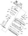
도 6은 본 발명에 따른 헤드에 장착되는 카트리지의 사시도이다.
도 7은 도 6의 분해사시도이다.1 is a perspective view illustrating a head of an ultrasonic treatment apparatus according to the present invention.
Fig. 2 is a side view of Fig. 1. Fig.
Fig. 3 is another side view of Fig. 1. Fig.
4 is an exploded perspective view of a head body with an operating assembly in a head according to the present invention.
5 is a perspective view of a base plate according to the present invention.
6 is a perspective view of a cartridge mounted on a head according to the present invention.
7 is an exploded perspective view of Fig.
이하, 첨부된 도면을 참조하여, 본 발명의 실시예들을 설명하기로 한다. 각 도면에 제시된 동일한 부호는 동일한 부재를 나타낸다. 본 발명을 설명함에 있어, 관련된 공지 기능 혹은 구성에 관한 구체적인 설명은 본 발명의 요지를 모호하지 않게 하기 위하여 생략한다.Hereinafter, embodiments of the present invention will be described with reference to the accompanying drawings. The same reference numerals shown in the drawings denote the same members. In describing the present invention, a detailed description of known functions and configurations incorporated herein will be omitted so as to avoid obscuring the subject matter of the present invention.
도 1은 본 발명에 따른 초음파 치료장치의 헤드를 도시한 사시도, 도 2는 도 1의 일측면도, 도 3은 도 1의 타측면도, 도 4는 본 발명에 따른 헤드에서 작동 조립체가 있는 헤드몸체의 분해 사시도이다.2 is a side view of Fig. 1, Fig. 3 is another side view of Fig. 1, Fig. 4 is a perspective view of a head body with an operation assembly in the head according to the present invention, Fig. Fig.
본 발명에 따른 초음파 치료용 헤드(10)는 전체적인 형상이 시술자(예:의사)의 손으로 잡아 환자의 피부에 접촉시켜 치료하기 용이하도록 제작된다.The
초음파 치료용 헤드(10)는 내부에 제1액츄에이터(110)와 제2액츄에이터(120)가 내장된 헤드몸체(100)와, 헤드몸체(100)에 착탈 가능한 구조로서 헤드몸체(100)의 작동에 따라 초음파를 발생하면서 치료 영역인 피부를 따라 이동하면서 초음파를 조사하기 위한 카트리지(200)로 구성된다.The
여기서, 상기 치료 영역인 피부는 대체로 허벅지 등과 같이 평평한 형상을 가질 수도 있지만, 복부 등과 같이 곡선 형상을 가질 수도 있다.Here, the skin, which is the treatment area, may have a flat shape such as a thigh or the like, but may have a curved shape such as an abdomen.
본 발명은 상기와 같이 평평한 형상 또는 곡선 형상에 관계없이 피부를 따라 이동되면서 초음파를 조사하여 피하지방으로 초음파를 조사할 수 있는 것이 특징이다. 이에 따라, 항상 일정한 깊이로 초음파를 조사하여 침투시킬 수 있다.The present invention is characterized in that ultrasonic waves can be irradiated to subcutaneous fat by irradiating ultrasonic waves while moving along the skin irrespective of the flat shape or the curved shape as described above. Accordingly, it is possible to always irradiate ultrasound at a constant depth and infiltrate.
이러한 본 발명에 따른 초음파 치료용 헤드(10)는 휴대 가능한 독립형으로 구현될 경우, 전원이 공급되면 헤드몸체(100)의 내부에 컨트롤러를 구비한다. 초음파 치료용 헤드(10)는 컨트롤러의 제어에 의해 독립적으로 작동할 수 있다.When the
그러나, 안정적인 전원의 공급 및 간편한 조작을 위해 외부에 별도로 컨트롤러를 두는 것이 더 바람직할 것이다.However, it would be more desirable to have a controller separately on the outside for stable power supply and easy operation.
상기와 같이 외부에 별도로 컨트롤러를 두는 경우에는 헤드몸체(100)와 외부의 컨트롤러가 유선 케이블 등으로 연결될 수 있다.When the controller is separately provided on the outside as described above, the
도 1 내지 도 3을 참조하면, 본 발명에 따른 초음파 치료용 헤드(10)는 헤드몸체(100)와 헤드몸체(100)의 하부에 탈착 가능한 카트리지(200)로 구성된다.1 to 3, the
헤드몸체(100)는 내부에 소자들을 지지 및 보호하고 디스플레이부를 매개로 사용자에게 인터페이스를 제공하기 위한 몸체 하우징(도시 생략함), 베이스판(300), 제1축에서 상하로 병진(왕복)운동을 발생시키며, 상기 베이스판(300)의 상면에 설치되는 제1액츄에이터(110), 제2축에서 상하로 병진(왕복)운동을 일으키며, 상기 베이스판(300)의 상면에 설치되는 제2액츄에이터(120), 베이스판(300)의 하면에 고정설치되는 제1볼베어링(1)을 축의 중심으로 제1액츄에이터(110)와 제2액츄에이터(120)에 의해 피봇 운동하는 스테이지(130)로 구성된다.The
상기 제1액츄에이터(110)와 제2액츄에이터(120)는 동일하게 병진운동될 수도 있으나, 개별적으로 병진운동될 수도 있다.The
상기 카트리지(200)는 나중에 자세히 설명하는 바와 같이, 상기 헤드몸체(100)의 하부에 결합되며, 내부에는 트랜스듀서(226)를 수용하면서 액체를 밀봉시키기 위한 카트리지 하우징(212), 이 카트리지 하우징(212)에 설치되어 초음파를 치료영역으로 전달하기 위한 평면 윈도우(도 7의 228), 스테이지(130)의 피봇 운동에 의해 평면 윈도우(228)의 내측면을 따라 트랜스듀서(226)를 평면 이동시키기 위한 피팅부재로 구성된다.The
또한, 상기 피팅부재는 스테이지(130)의 하부와 연결되는 연결부(204), 연결부(204)의 하부에 결합되며 내부에는 삽입부(미도시)가 형성되는 제1서포트(214), 제1서포트(214)의 상부 개구를 통해 삽입부에 설치되는 압축스프링(216), 삽입부로 삽입되어 스테이지(130)의 피봇운동에 의해 승하강되면서 압축스프링(216)을 압축하는 제2서포트(218), 제2서포트(218)의 하부에 설치되는 제4볼조인트(4) 및 내부에는 피부로 초음파를 조사하기 위한 트랜스듀서(226)가 수용되며, 제4볼조인트(4)와 결합되는 트랜스듀서 하우징(224)으로 구성된다.The fitting member includes a
상기 트랜스듀서 하우징(224)은 제2서포트(218)의 상하운동에 의해 압축스프링(216)에 저장된 탄성복원력이 작용되면, 카트리지 하우징(212)의 내부에서 평면 윈도우(228)의 상면을 따라 밀착된 상태로 이동되도록 하여 초음파가 피부로 조사되도록 한다.The
상기 평면 윈도우(228)는 일정한 탄성을 가지며, 피부에 밀착될 수 있도록 형상이 일부 가변되는 합성수지의 필름으로 제작될 수 있다. 이에 따라, 피부의 형상대로 가변되며, 트랜스듀서 하우징(224)은 평면 윈도우(228)의 상면을 따라 이동되므로 본 발명은 피부의 형상을 따라 트랜스듀서(226)가 초음파를 조사할 수 있는 것이 특징이다.The
도 4는 본 발명에 따른 초음파 치료용 헤드에서 작동 조립체가 있는 헤드몸체의 분해 사시도이다.4 is an exploded perspective view of a head body having an operating assembly in an ultrasonic treatment head according to the present invention.
도 4를 참조하면, 제1축에서 병진(왕복)운동을 발생시키는 제1액츄에이터(110)는 모터(111), 모터(111)의 회전축과 리드 스크류(113)를 결합하기 위한 커플러(112), 모터(111)에 의해 좌우로 회전되는 리드 스크류(113), 리드 스크류(113)를 지지하기 위한 지지 프레임(117), 리드 스크류(113)의 외주면에 결합되되, 모터(111)에 의해 리드 스크류(113)의 외주면을 따라 상하로 왕복운동하는 슬라이더(114), 슬라이더(114)가 리드 스크류(113)의 외주면을 따라 이동시, 슬라이더(114)의 자유회전을 방지함과 동시에 승하강(직선운동)되도록 가이드하는 가이드봉(118), 슬라이더(114)의 위치를 검출하기 위한 위치저항(116), 슬라이더(114)의 선단에 장착되는 제1구동축(140)으로 구성되며, 제1구동축(140)은 도 5에 도시된 베이스판(300)에 타공된 제1작동홀(310)을 관통하여 스테이지(130)와 연결된다.4, a
또한, 제2축에서 병진(왕복)운동을 발생시키는 제2액츄에이터(120)는 제1액츄에이터와 동일하게 모터(121), 커플러(122), 리드 스크류(123), 리드 스크류(123)와, 지지 프레임(127), 슬라이더(124), 가이드봉(128), 위치저항(126) 및 제2구동축(240)으로 구성된다.The
상기 제2구동축(240)은 상술한 제1구동축(140)과 동일하게 베이스판(300)에 타공된 제2작동홀(320)을 관통하여 스테이지(130)와 연결된다.The second driving shaft 240 is connected to the
즉, 상기 제1구동축(140)과 제2구동축(240)의 일측은 각각 슬라이더(114, 124)에 연결되어 액츄에이터의 작동을 스테이지에 전달하기 위한 매개체이며, 제1구동축(140)과 제2구동축(150)의 타측에는 제2볼조인트(2)와 제3볼조인트(3)가 각각 구비된다.One side of the
본 발명에 있어서 상기 제1액츄에이터(110)와 제2액츄에이터(120)는 서로 동일한 한 쌍의 부재이며, 이러한 제1액츄에이터(110)와 제2액츄에이터(120)는 베이스판(300)의 상면에 설치되되, 도 1 내지 도 3에 도시된 바와 같이, 베이스판(300)의 중앙을 기준으로 서로 수직하게 배치되되, 베이스판(300)의 중앙에서 동일한 거리에 이격 배치되는 것이 바람직하다.The
상기와 같이 제1액츄에이터(110)와 제2액츄에이터(120)가 베이스판(300)의 중앙에서 동일한 위치와 거리 이격되어 배치되는 경우, 제1액츄에이터(110)와 제2액츄에이터(120)에 의해 구동되는 스테이지(130)를 제어하기 용이할 것이다.When the
한편, 상기 베이스판(300)에는 도 5에 도시된 바와 같이, 제1작동홀(310)과 제2작동홀(320)이 관통형성된다. 상기 제1작동홀(310)과 제2작동홀(320)에는 제1가동축(140)과 제2가동축(150)이 각각 관통되어 베이스판(300)의 하부에 배치되는 스테이지(130)와 연결된다.As shown in FIG. 5, the
상기 제1가동축(140)은 제1액츄에이터(110)와 스테이지(130)의 제1블럭(131)을 연결하며, 제2가동축(150)은 제2액츄에이터(210)와 스테이지(130)의 제2블럭(132)을 연결한다.The first
여기서, 상기 제1가동축(140)과 제2가동축(150)의 일측(상부)은 각각 제1액츄에이터(110)와 제2액츄에이터(120)의 슬라이더(114, 124)에 개별적으로 결합된다. 상기 제1가동축(140)과 제2가동축(150)의 타측(하부)은 각각 제1블럭(310)과 제2블럭(320)에 결합된다. 상기 제1가동축(140)과 제2가동축(150)의 타측 단부에는 각각 제2볼조인트(2)와 제3볼조인트(3)가 구비된다.One side (upper portion) of the first
상기 제1블럭(131)과 제2블럭(132)은 힌지를 매개로 연결되되, 제2블럭(320)이 제1블럭(310)에 좌우로 회전가능하게 결합된다.The
상기 제2볼조인트(2)와 제3볼조인트(3)는 각각 제1블럭(131)과 제2블럭(132)에 결합되는데, 제2볼조인트(2)과 제3볼조인트(3)는 상기 제1블럭(131)과 제2블럭(132)에 형성된 가동홈(미도시)에 각각 회전가능하게 끼움결합된다.The second ball joint 2 and the third ball joint 3 are coupled to the
또한, 상기 가동홈은 제2볼조인트(2)와 제3볼조인트(3)의 횡방향 움직임이 일부 허용되도록 제1블럭(131)과 제2블럭(132)의 길이방향을 따라 일정한 길이를 갖도록 형성될 수 있다.The movable groove has a predetermined length along the longitudinal direction of the
이에 따라, 제2볼조인트(2)와 제3볼조인트(3)는 가동홈에 회전가능하게 결합되면서, 이와 동시에 일부 이동이 가능하다.Accordingly, the second ball joint 2 and the third ball joint 3 are rotatably coupled to the movable groove, and at the same time, some movement is possible.
또한, 상기 스테이지(130)는 베이스판(300)의 하부와 피봇축(400)을 매개로 연결되는데, 이러한 피봇축(400)의 하부에는 제1볼조인트(1)가 구비된다.The
상기 제1볼조인트(1)에 의해 스테이지(130)는 베이스판(300)의 하부에서 회전가능하게 연결되며, 피봇축(400)은 스테이지(130)의 회전의 중심축이된다. 이러한 제1볼조인트(1)는 상술한 제2볼조인트(2) 및 제3볼조인트(3)와는 다르게 횡방향으로 이동되지 아니한다.The
즉, 상기 스테이지(130)는 제1볼조인트(1)를 피봇운동의 축으로 하여 베이스판(300)에 대하여 피봇운동하며, 제1액츄에이터(110)와 제2액츄에이터(120)의 상하 병진운동에 의해 상하 및 좌우로 자유롭게 작동될 수 있다.That is, the
상기 스테이지(130)는 베이스판(300)의 하면과 제1볼조인트(1)를 매개로 회전가능하게 결합되는 부재로서, 이러한 스테이지(130)는 제1블럭(131)과 제2블럭(132)으로 구성된다.The
상기 제1블럭(131)은 베이스판(300)의 하면과 피봇축(400)의 하부에 구비된 제1볼조인트(1)를 매개로 연결된다. 상기 제2블럭(132)은 제1블럭(131)과 힌지를 매개로 좌우로 회전가능하게 결합되되, 제2블럭(132)이 제1블럭(131)에 대하여 좌우로 회전되는 회전각은 제어(예:120도)될 수도 있다.The
상술한 제2볼조인트(2)는 제1블럭(131)과 연결되며, 제3볼조인트(3)는 제2블럭(132)과 연결되되, 제1블럭(131)과 제2블럭(132)에는 제2볼조인트(2)와 제3볼조인트(3)가 끼워져 횡방향으로 이동될 수 있도록 가동홈이 각각 형성된다.The second ball joint 2 is connected to the
다시말하면, 제1블럭(131)과 제2블럭(132)으로 구성되는 상기 스테이지(130)는 제1볼조인트(1)에 의해 축이 고정된 상태에서 제1액츄에이터(110)와 제2액츄에이터(120)의 병진운동에 의해 제2볼조인트(2)와 제3볼조인트(3)가 가동홈의 길이방향을 따라 일부 이동되면서 피봇운동한다.In other words, the
한편, 상기 스테이지(130)의 하부에는 피팅부재의 연결부(204)와 연결되는 결합용 자석(133)이 구비되는데, 이러한 결합용 자석(133)에 의해 피팅부재는 스테이지(130)의 피봇운동을 전달받으며, 이에 대한 상세한 설명은 후술한다.The
미설명부호 134는 후술할 피팅부재와의 결합을 위한 부재이며, 미설명부호 L은 슬라이더(114, 124)를 감지하기 위한 리미트 스위치이고, 미설명부호 P는 컨트롤러와 입력부(150)와 연결되어 후술할 카트리지 PCB(202)와 연결되는 PCB이다
도면에는 자세히 도시하지 않았으나 피팅부재와 결합용 자석(133)은 자력에 의해 강하게 결합되어 스테이지(130)의 운동에 따라 카트리지(120)의 피팅부재가 트랜스듀서(226)를 움직일 수 있도록 되어 있다.Although not shown in the drawings, the fitting member and the
그리고, 헤드몸체(100)에는 몸체 하우징에 장착되어 사용자와의 인터페이스를 제공하기 위한 디스플레이(미도시) 또는 터치스크린(미도시), 소정의 작동 알고리즘에 따라 프로그래밍된 소프트웨어를 실행하여 제1액츄에이터(110)와 제2액츄에이터(120)의 동작을 제어하고, 트랜스듀서(226)를 구동하기 의한 컨트롤보드(142)가 구비되어 있다. 각 액츄에이터(110, 120)의 위치저항(116,126)은 컨트롤보드(142)로 연결되어 슬라이더(114,124)가 상한이나 하한 위치에 도달하면 각 액츄에이터(110, 120)의 회전방향을 전환하게 한다.The
헤드몸체(100)에는 이와 같은 구성외에도 카트리지(200)가 잘 결합되었는지 확인하기 위한 감지센서 등이 추가 설치될 수 있다.In addition to the above-described configuration, the
도 6은 본 발명에 따른 헤드에 장착되는 카트리지의 사시도, 도 7은 도 6의 분해사시도이다.FIG. 6 is a perspective view of a cartridge mounted on a head according to the present invention, and FIG. 7 is an exploded perspective view of FIG.
도 6 내지 도 7을 참조하면, 카트리지(200)는 카트리지 PCB(202), 연결부(204), 자바라 지지링(206), 자바라(208), 상커버(210), 카트리지 하우징(212), 제1서포트(214), 압축 스프링(216), 제2서포트(218), 트랜스듀서 하우징(224), 트랜스듀서(226), 평면 윈도우(228), 하커버(230)로 구성된다.6 to 7, the
상기 카트리지 PCB(202)는 컨트롤러에 연결되며, 도 1 내지 도 4에 도시된 입력부(150)에 의해 제어되는 부재이다. 상기 카트리지 PCB(202)에는 헤드몸체(100)의 리드 커넥터를 통해 후술할 트랜스듀서(226)의 구동을 위한 전원을 공급받는 단자(미도시)와 컨트롤러와 입력부(150)로부터 트랜스듀서(226)의 구동패턴을 입력받는 단자(미도시) 등이 구비될 수 있으며, 상기 카트리지 PBC(202)와 트랜스듀서(226)는 도시되지 않은 전선으로 연결되어야 할 것이다.The
상기 연결부(204)는 헤드몸체(100)와 결합을 위한 부재로서, 헤드몸체(100)의 접촉 커넥터 및 결합부와 체결되어 스테이지(130)의 피봇 운동과 컨트롤보드(142)의 전기신호를 연결하도록 되어있다.The
상기 연결부(204)에는 결합용 자석(133)과 자력으로 결합되기 위한 또 다른 결합용 자석(203)이 구비되는데, 이러한 또 다른 결합용 자석(203)은 별도의 고정브라켓(205)을 이용하여 연결부(204)에 설치될 수 있다.The
상기 자바라(208)는 자바라 지지링(206)에 의해 카트리지 하우징(212)과 체결되어 내부에 트랜스듀서(226)의 움직임을 허용하면서 내부의 액체가 외부로 누출되지 않도록 밀봉시키는 역할을 한다.The bellows 208 is fastened to the
상기 평면 윈도우(228)는 카트리지 하우징(212)에 설치되어 초음파를 치료영역으로 전달하는 역할을 한다.The
이때, 상커버(210)와 하커버(230)는 카트리지 하우징(212)과 체결되어 자바라(208) 및 평면 윈도우(228)와 함께 카트리지(200)의 내부 공간을 밀봉시켜 초음파를 전달하기 위한 매체인 액체가 누출되지 않게 한다.The
피팅부재는 스테이지(130)의 하부와 연결되는 연결부(204), 카트리지 하우징(212)의 내부에서 연결부(204)의 하부에 결합되며, 하부가 개구된 삽입부가 길이방향을 따라 형성되는 제1서포트(214), 제1서포트(214)의 내부에 설치되는 압축스프링(216), 상부가 상기 삽입부로 삽입되며, 스테이지(130)의 피봇운동에 의해 승하강되면서 압축스프링(216)을 압축할 수 있는 제2서포트(218), 제2서포트(218)의 하부에 구비되는 제4볼조인트(4) 및 제4볼조인트(4)와 회전가능하게 결합되는 트랜스듀서 하우징(224)이 포함된다.The fitting member includes a connecting
상기 트랜스듀서 하우징(224)은 내부에 트랜스듀서(226)가 수용되며, 압축스프링(216)에 저장된 탄성복원력에 의해 평면 윈도우(228)의 상면에 밀착되어 이동된다.The
상기 피팅부재는 트랜스듀서 하우징(224)과 제4볼조인트(4)의 결합 및 압축스프링(216)에 저장된 탄성복원력과 연결부(204)를 통해 전달되는 스테이지(130)의 피봇 운동에 의해 평면 윈도우(228)의 상면에 밀착되어 초음파를 따라 초음파 트랜스듀서(226)를 이동시킨다.The fitting member is elastically restored by a combination of the
이에 따라, 트랜스듀서 하우징(224)에 구비된 트랜스듀서(226)는 평면 윈도우(228)의 상면을 따라 피부로 초음파를 조사할 수 있다. 상기 트랜스듀서(226)는 트랜스듀서 하우징(224)에 체결되어 구동신호가 입력되면 초음파를 발생시킨다.Accordingly, the
한편, 제2서포트(218)의 외주면에는 분리방지돌기(217)가 형성되고, 제1서포트의 내벽에는 분리방지턱(미도시)이 형성된다.On the other hand, a
상기 분리방지턱에 의해 제2서포트(218)는 제1서포트(214)에서 분리되는 것이 방지된다.The
또한, 상기 제1서포트(214)의 외주면에는 헤드몸체(100)와 카트리지(200)의 분리시, 카트리지 하우징(212)의 내부에 배치된 부재들이 카트리지 하우징(212)의 외부로 이탈되는 것을 제한하여 자바라(206)의 파손을 방지하기 위한 스톱퍼(215)가 더 포함되는 것이 바람직할 것이다.The outer circumferential surface of the first support 214 restricts the members disposed in the
미설명부호 201은 카트리지(200)와 헤드몸체(100)의 결합을 위한 브라켓이다.
이어서, 이와 같이 구성되는 본 발명에 따른 초음파 치료용 헤드의 동작을 설명하기로 한다.Next, the operation of the ultrasonic treatment head constructed as described above according to the present invention will be described.
통상 초음파 치료는 치료 목적에 따라 촛점 영역의 깊이가 달라지므로 치료목적에 맞는 카트리지(200)를 선택하여 헤드몸체(100)에 장착한다. 또한, 치료부위나 목적에 따라 트랜스듀서(226)의 작동 패턴이나 동작 시간을 선택할 수도 있다.Since the depth of the focal area differs depending on the therapeutic purpose, the conventional ultrasound therapy selects the
초음파 치료용 헤드(10)의 사용자 인터페이스를 통해 초음파 치료용 헤드(10)를 작동시키면, 컨트롤러가 미리 프로그램된 패턴에 따라 제1액츄에이터(110)와 제2액츄에이터(120)를 구동하고, 트랜스듀서(226)를 작동시켜 초음파 혹은 고집속초음파(HIFU)가 발생되게 한다.When the
제1액츄에이터의 모터(111)가 회전되면 커플러(112)를 통해리드 리드 스크류(113)가 회전되고, 리드 스크류(113)에 체결된 슬라이더(114)가 스크류(113)를 따라 하방으로 이동하게 되면서 슬라이더(140)에 연결된 제1구동축(140)이 하방으로 이동하게된다.When the
이때, 제1구동축(140)에 구비된 제2볼조인트(2)가 하방으로 이동하면 스테이지(130)은 피봇축(400)의 제1볼조인트(1)를 축으로 하여 피봇운동하게 된다.At this time, when the second ball joint 2 provided on the
이와 동일한 방식으로, 제2액츄에이터(120)도 동작하게 되면, 스테이지(130)는 제1볼조인트(1)와 제2볼조인트(2)에 의한 피봇운동과 제3볼조인트(3)에 의한 피봇운동이 결합되어 다양한 방향으로 피봇운동을 일으키게 된다.In this way, when the
제1액츄에이터(110)의 슬라이더(114)가 하한 위치에 도달한 것을 위치저항(116)을 통해 검출하게 되면, 컨트롤러는 제1액츄에이터(110)의 회전방향을 반대방향으로 변환하여 회전시키게 되고, 이에 따라 슬라이더(114)는 상방으로 이동하게 된다. 동일한 방식으로 제1액츄에이터(110)의 슬라이더(114)가 상한 위치에 도달한 것을 위치저항(116)을 통해 검출하게 되면, 컨트롤러는 제1액츄에이터(110)의 회전방향을 다시 반대방향으로 변환하여 다시 하향으로 이동하게 하고, 이에 따라 슬라이더(114)는 상한과 하한 사이를 왕복운동하면서 스테이지(130)를 밀거나 당기게 된다.When the
한편, 스테이지(130)의 피봇운동은 카트리지(200)의 피팅부재로 전달되고, 피팅부재는 피봇운동에 의해 평면 선단에 장착된 트랜스듀서(226)를 평면윈도우(228)를 따라 이동시키게 된다.On the other hand, the pivotal movement of the
이때, 피팅부재는 압축 스프링(216)에 의해 전체 축의 길이가 가변되어 피봇운동을 평면운동으로 전환하여 트랜스듀서(226)에서 조사되는 초음파가 평면으로 조사되도록 한다.At this time, the length of the entire axis of the fitting member is varied by the
즉, 평면 윈도우(228)의 중앙에서는 피팅부재의 길이가 짧아지고 압축스프링(216)이 많이 압축되어 있다가 주변으로 이동하면서 압축 스프링(216)에 저장되어 있던 탄성복원력이 작용하면서 피팅부재의 길이가 늘어 나게 되어 평면 윈도우 (228)영역에서는 초음파가 평면으로 조사가 되도록 하고, 이에 따라 트랜스듀서(226)의 초음파 촛점 깊이가 중앙이나 주변이 모두 균일한 평면을 이루게 된다.That is, at the center of the
도면과 명세서에서 최적의 실시예들이 개시되었다. 여기서, 특정한 용어들이 사용되었으나, 이는 단지 본 발명을 설명하기 위한 목적에서 사용된 것이지 의미한정이나 특허청구범위에 기재된 본 발명의 범위를 제한하기 위하여 사용된 것은 아니다. 그러므로, 본 기술 분야의 통상의 지식을 가진자라면, 이로부터 다양한 변형 및 균등한 타 실시예가 가능하다는 점을 이해할 것이다. 따라서, 본 발명의 진정한 기술적 보호범위는 첨부된 특허청구범위의 기술적 사상에 의해 정해져야 할 것이다.Optimal embodiments have been disclosed in the drawings and specification. Although specific terms are used herein, they are used for the purpose of describing the present invention only and are not used to limit the scope of the present invention described in the claims or the claims. Therefore, it will be understood by those skilled in the art that various changes and modifications may be made without departing from the scope of the present invention. Accordingly, the true scope of the present invention should be determined by the technical idea of the appended claims.
1-제1볼조인트2-제2볼조인트
3-제3볼조인트4-제4볼조인트
10-초음파 치료용 헤드
100-헤드몸체
110-제1액츄에이터111-모터
112-커플러113-리드 스크류
114-슬라이더116-위치저항
117-지지 프레임118-가이드봉
120-제2액츄에이터121-모터
122-커플러123-리드 스크류
124-슬라이더126-위치저항
127-지지 프레임128-가이드봉
130-스테이지131-제1블럭
132-제2블럭133-결합용 자석
140-제1구동축
150-제2구동축
200-카트리지202-카트리지 PCB
203-결합용 자석204-연결부
205-고정브라켓210-상커버
212-카트리지 하우징214-제1서포트
215-스톱퍼216-압축스프링
217-분리방지돌기218-제2서포트
224-트랜스듀서 하우징226-트랜스듀서
228-평면 윈도우230-하커버
300-베이스판310-제1작동홀
320-제2작동홀
400-피봇축1-first ball joint 2-second ball joint
3- Third Ball Joint 4- Fourth Ball Joint
10-Head for ultrasound therapy
100-head body
110 - first actuator 111 - motor
112-Coupler 113-Lead Screw
114 - Slider 116 - Position Resistance
117-Support frame 118-Guide rod
120 - second actuator 121 - motor
122-Coupler 123-Lead Screw
124-slider 126-position resistance
127-support frame 128-guide rod
130-Stage 131-The first block
132-second block 133-coupling magnet
140-
150-second drive shaft
200-Cartridge 202-Cartridge PCB
203-coupling magnet 204-connection portion
205-fixing bracket 210-upper cover
212-Cartridge housing 214-First support
215-stopper 216-compression spring
217-Detachment protrusion 218-Second support
224-transducer housing 226-transducer
228-plane window 230-bottom cover
300-base plate 310-first working hole
320-second working hole
400-pivot axis
Claims (20)
Translated fromKorean상기 헤드몸체에 탈착되되, 내부에는 트랜스듀서와 액체가 밀봉되는 카트리지 하우징, 이 카트리지 하우징에 설치되어 상기 트랜스듀서에서 발생되는 초음파를 치료영역으로 전달하기 위한 평면 윈도우, 상기 스테이지의 피봇운동에 의해 상기 트랜스듀서가 상기 평면 윈도우의 상면에 밀착되어 이동되도록 하는 피팅부재로 구성되는 카트리지를 포함하는 것을 특징으로 하는 초음파 치료용 헤드.A head body including a first actuator and a second actuator, and a stage pivotally moved by the first actuator and the second actuator,
A cartridge housing in which a transducer and a liquid are sealed, the cartridge housing being detachably attached to the head body, the cartridge housing having a flat window for transmitting ultrasound generated from the transducer to a treatment area, And a fitting member for allowing the transducer to move close to the upper surface of the plane window.
상기 헤드몸체에는,
상기 제1액츄에이터와 상기 제2액츄에이터가 상면에 설치되고, 하부에는 상기 스테이지가 배치되는 베이스판이 더 포함되는 것을 특징으로 하는 초음파 치료용 헤드.The method according to claim 1,
In the head body,
Further comprising a base plate on which the first actuator and the second actuator are installed, and a base plate on which the stage is disposed.
상기 헤드몸체는,
사용자에게 사용자 인터페이스를 제공하기 위한 디스플레이부가 더 포함되는 것을 특징으로 하는 초음파 치료용 헤드.The method of claim 2,
The head body includes:
And a display unit for providing a user interface to the user.
상기 헤드몸체와 연결되는 외부 본체가 더 포함될 수 있으며,
상기 외부 본체에는,
상기 제1액츄에이터 및 제2액츄에이터를 제어하기 위한 콘트롤러가 더 포함될 수 있는 것을 특징으로 하는 초음파 치료용 헤드.The method of claim 2,
And an external body connected to the head body,
In the external body,
And a controller for controlling the first actuator and the second actuator can be further included.
상기 제1액츄에이터 및 제2액츄에이터는,
모터와,
상기 모터에 의해 좌우로 회전되는 리드 스크류와,
상기 리드 스크류의 외주면에 결합되되, 상기 모터에 의해 상기 리드 스크류의 외주면에서 승하강되는 슬라이더와,
상기 슬라이더가 상기 리드 스크류의 외주면을 따라 승하강되도록 하기 위한 가이드봉이 포함되는 것을 특징으로 하는 초음파 치료용 헤드.The method of claim 2,
The first actuator and the second actuator may comprise:
A motor,
A lead screw rotated right and left by the motor,
A slider coupled to an outer circumferential surface of the lead screw and raised and lowered by an outer circumferential surface of the lead screw by the motor;
And a guide rod for moving the slider upward and downward along the outer circumferential surface of the lead screw.
상기 베이스판에 형성되는 제1작동홀 및 제2작동홀과,
상기 제1작동홀 및 제2작동홀을 관통하며, 일측은 상기 슬라이더에 결합되고, 타측은 상기 스테이지와 결합되는 제1가동축 및 제2가동축이 더 포함되는 것을 특징으로 하는 초음파 치료용 헤드.The method of claim 5,
A first operation hole and a second operation hole formed in the base plate,
Further comprising a first movable shaft and a second movable shaft passing through the first actuating hole and the second actuating hole and having one side coupled to the slider and the other side coupled to the stage. .
상기 스테이지는,
상기 베이스판의 하면과 피봇축을 매개로 연결되는 제1블럭과,
상기 제1블럭과 힌지를 매개로 좌우로 회전가능하게 결합되는 제2블럭을 포함하며,
상기 피봇축의 하부는 제1블럭과 제1볼조인트를 매개로 연결되는 것을 특징으로 하는 초음파 치료용 헤드.The method of claim 6,
The stage includes:
A first block connected to the lower surface of the base plate through a pivot shaft,
And a second block rotatably coupled to the first block via the hinge,
And a lower portion of the pivot shaft is connected to the first block through a first ball joint.
상기 제1블럭은 상기 제1작동홀을 관통하는 제1가동축의 타측에 구비된 제2볼조인트와 회전가능하게 연결되고,
상기 제2블럭은 상기 제2작동홀을 관통하는 제2가동축의 타측에 구비된 제3볼조인트와 회전가능하게 연결되는 것을 특징으로 하는 초음파 치료용 헤드.The method of claim 7,
Wherein the first block is rotatably connected to a second ball joint provided on the other side of the first movable shaft passing through the first actuating hole,
And the second block is rotatably connected to a third ball joint provided on the other side of a second movable shaft passing through the second actuating hole.
상기 제1블럭 및 2블럭에는 상기 제2볼조인트 및 제3볼조인트가 끼워져 횡방향으로 이동될 수 있는 가동홈이 형성되는 것을 특징으로 하는 초음파 치료용 헤드.The method of claim 8,
Wherein the first block and the second block are formed with movable grooves in which the second ball joint and the third ball joint are inserted to be movable in the lateral direction.
상기 스테이지는,
상기 제1볼조인트에 의해 상기 베이스판에 대하여 피봇운동하는 것을 특징으로 하는 초음파 치료용 헤드.The method of claim 7,
The stage includes:
Wherein the first ball joint pivotally moves with respect to the base plate.
상기 카트리지는, 상기 헤드몸체의 하부에 결합되며,
상기 평면 윈도우는 상기 카트리지 하우징의 하부 개구에 설치되는 것을 특징으로 하는 초음파 치료용 헤드.The method according to claim 1,
Wherein the cartridge is coupled to a lower portion of the head body,
Wherein the planar window is installed in a lower opening of the cartridge housing.
상기 피팅부재는,
상기 스테이지의 하부와 연결되는 연결부와,
상기 카트리지 하우징의 내부에서 상기 연결부의 하부에 결합되며, 하부가 개구된 삽입부가 형성된 제1서포트와,
상기 제1서포트의 내부에 설치되는 압축스프링과,
상부가 상기 삽입부로 삽입되며, 상기 스테이지의 피봇운동에 의해 승하강되어 상기 압축스프링을 압축하는 제2서포트와,
상기 제2서포트의 하부에 설치되는 제4볼조인트와,
상기 제4볼조인트와 결합되며, 내부에는 상기 트랜스듀서가 수용되고, 상기 압축스프링에 저장된 탄성복원력에 의해 상기 평면 윈도우의 상면에 밀착되어 이동하는 트랜스듀서 하우징이 더 포함되는 것을 특징으로 하는 초음파 치료용 헤드.The method according to claim 1,
Wherein the fitting member comprises:
A connection portion connected to a lower portion of the stage,
A first support coupled to a lower portion of the connection portion inside the cartridge housing,
A compression spring installed inside the first support,
A second support which is inserted into the insertion portion and whose upper portion is inserted into the insertion portion and is raised and lowered by the pivotal motion of the stage to compress the compression spring,
A fourth ball joint installed at a lower portion of the second support,
And a transducer housing coupled to the fourth ball joint, the transducer housing being accommodated in the interior of the fourth ball joint, and moving in close contact with an upper surface of the plane window by an elastic restoring force stored in the compression spring. Head.
상기 제2서포트의 외주면에 형성되는 분리방지돌기와,
상기 제1서포트의 내벽에 형성되어 상기 제2서포트가 상기 제1서포트에서 분리되는 것을 방지하기 위한 분리방지턱이 더 포함되는 것을 특징으로 하는 초음파 치료용 헤드.The method of claim 12,
A detachment protrusion formed on an outer circumferential surface of the second support,
Further comprising a separation preventing tab formed on an inner wall of the first support to prevent the second support from being separated from the first support.
상기 연결부는,
리드 커넥터를 통해 컨트롤러와 접속되는 카트리지 PCB와,
상기 스테이지에 의한 움직임을 허용하면서 상기 액체를 밀봉하기 위한 자바라가 포함되는 것을 특징으로 하는 초음파 치료용 헤드.The method of claim 12,
The connecting portion
A cartridge PCB connected to the controller through a lead connector,
And a bellows for sealing the liquid while permitting movement by the stage.
상기 연결부는 상기 스테이지의 하부와 결합용 자석을 매개로 연결되며,
상기 제1서포트의 외주면에는 상기 스테이지의 하부와 결합용 자석의 분리시, 상기 연결부가 상기 카트리지 하우징의 외부로 이탈되는 것을 방지하기 위한 스톱퍼가 더 포함되는 것을 특징으로 하는 초음파 치료용 헤드.The method of claim 12,
Wherein the connection portion is connected to a lower portion of the stage via a coupling magnet,
Further comprising a stopper on an outer circumferential surface of the first support to prevent the connection portion from being detached to the outside of the cartridge housing when the lower portion of the stage and the coupling magnet are separated from each other.
Applications Claiming Priority (2)
| Application Number | Priority Date | Filing Date | Title |
|---|---|---|---|
| KR20140145219 | 2014-10-24 | ||
| KR1020140145219 | 2014-10-24 |
Related Child Applications (2)
| Application Number | Title | Priority Date | Filing Date |
|---|---|---|---|
| KR1020150178117ADivisionKR101643885B1 (en) | 2015-12-14 | 2015-12-14 | Ultrasonic cartridge |
| KR1020160076614ADivisionKR101824465B1 (en) | 2014-10-24 | 2016-06-20 | Head of ultrasonic therapy system for treatment |
Publications (2)
| Publication Number | Publication Date |
|---|---|
| KR20160048641A KR20160048641A (en) | 2016-05-04 |
| KR101635636B1true KR101635636B1 (en) | 2016-07-01 |
Family
ID=55761045
Family Applications (2)
| Application Number | Title | Priority Date | Filing Date |
|---|---|---|---|
| KR1020150131026AActiveKR101635636B1 (en) | 2014-10-24 | 2015-09-16 | And head of ultrasonic therapy system for treatment |
| KR1020160076614AActiveKR101824465B1 (en) | 2014-10-24 | 2016-06-20 | Head of ultrasonic therapy system for treatment |
Family Applications After (1)
| Application Number | Title | Priority Date | Filing Date |
|---|---|---|---|
| KR1020160076614AActiveKR101824465B1 (en) | 2014-10-24 | 2016-06-20 | Head of ultrasonic therapy system for treatment |
Country Status (6)
| Country | Link |
|---|---|
| US (1) | US20170303888A1 (en) |
| EP (1) | EP3210649B1 (en) |
| KR (2) | KR101635636B1 (en) |
| CN (1) | CN107073290B (en) |
| AU (1) | AU2014409333B2 (en) |
| WO (1) | WO2016064016A1 (en) |
Cited By (1)
| Publication number | Priority date | Publication date | Assignee | Title |
|---|---|---|---|---|
| KR102135733B1 (en)* | 2019-12-16 | 2020-07-20 | (주)클래시스 | ULTRASONIC GENERATOR FOR THERAPY AND ltrasonic generator for therapy and ULTRASONIC HANDDPIECE INCLUDING THE SAME |
Families Citing this family (12)
| Publication number | Priority date | Publication date | Assignee | Title |
|---|---|---|---|---|
| WO2017176009A1 (en)* | 2016-04-05 | 2017-10-12 | (주)클래시스 | Ultrasonic transducer exercise apparatus and ultrasonic therapeutic head using same |
| KR101775694B1 (en)* | 2016-05-04 | 2017-09-06 | (주)클래시스 | Moving apparatus for ultrasonic transducer and head of ultrasonic therapy system for treatment thereof |
| KR101782523B1 (en)* | 2016-05-04 | 2017-10-23 | (주)클래시스 | Moving apparatus for ultrasonic transducer and head of ultrasonic therapy system for treatment thereof |
| KR101677903B1 (en)* | 2016-05-16 | 2016-11-21 | 정성재 | Ultrasonic cartridge and head of ultrasonic therapy system for treatment |
| KR101688424B1 (en)* | 2016-05-30 | 2017-01-02 | 정성재 | Ultrasonic cartridge and head of ultrasonic therapy system for treatment |
| KR101824462B1 (en)* | 2016-12-29 | 2018-02-01 | (주)클래시스 | Ultrasonic cartridge and head of ultrasonic therapy system for treatment |
| CN108324324A (en)* | 2018-03-12 | 2018-07-27 | 西安交通大学 | It is a kind of ultrasound low frequency through cranial capacity super-resolution three-dimensional contrast imaging method and system |
| CN109821161A (en)* | 2019-03-22 | 2019-05-31 | 常州立新医疗美容诊所有限公司 | A kind of medical treatment shaping fat melting equipment |
| CN110664437B (en)* | 2019-10-22 | 2024-09-13 | 深圳瀚维智能医疗科技有限公司 | Automatic ultrasonic breast scanning device |
| KR102521030B1 (en)* | 2020-09-09 | 2023-04-12 | 주식회사 제이시스메디칼 | Ultrasonic medical cartridge and ultrasound medical device including the same |
| CN115154253B (en)* | 2022-09-08 | 2022-11-08 | 苏州好博医疗器械股份有限公司 | Ultrasonic treatment head with automatic moving function |
| WO2025089446A1 (en) | 2023-10-23 | 2025-05-01 | (주)아이엠지티 | Ultrasound therapy head |
Citations (1)
| Publication number | Priority date | Publication date | Assignee | Title |
|---|---|---|---|---|
| KR101177691B1 (en)* | 2012-07-09 | 2012-08-29 | (주)클래시스 | 3 axis control head of therapy system for treatment of fatness using hifu |
Family Cites Families (13)
| Publication number | Priority date | Publication date | Assignee | Title |
|---|---|---|---|---|
| US5402789A (en)* | 1992-11-23 | 1995-04-04 | Capistrano Labs, Inc. | Ultrasonic peripheral vascular probe assembly |
| US8926533B2 (en)* | 2003-12-30 | 2015-01-06 | Liposonix, Inc. | Therapy head for use with an ultrasound system |
| US7695437B2 (en)* | 2003-12-30 | 2010-04-13 | Medicis Technologies Corporation | Ultrasound therapy head with movement control |
| CN1754586B (en)* | 2004-09-30 | 2010-09-01 | 重庆海扶(Hifu)技术有限公司 | Ultrasonic therapy head and ultrasonic therapy instrument containing same |
| JP5155693B2 (en)* | 2008-02-26 | 2013-03-06 | 東芝プラントシステム株式会社 | Ultrasonic inspection equipment |
| EP2331207B1 (en) | 2008-10-03 | 2013-12-11 | Mirabilis Medica Inc. | Apparatus for treating tissues with hifu |
| KR101117275B1 (en)* | 2009-07-22 | 2012-03-20 | 김완철 | Apparatus for removing fat using ultra sonic |
| US8932238B2 (en)* | 2009-09-29 | 2015-01-13 | Liposonix, Inc. | Medical ultrasound device with liquid dispensing device coupled to a therapy head |
| JP5933549B2 (en)* | 2010-08-18 | 2016-06-08 | ミラビリス メディカ インク | HIFU applicator |
| KR101191347B1 (en)* | 2010-10-20 | 2012-10-15 | (주)클래시스 | 3-dimension movable handpiece for high intensive focused ultrasound apparatus |
| US9289188B2 (en)* | 2012-12-03 | 2016-03-22 | Liposonix, Inc. | Ultrasonic transducer |
| KR101307551B1 (en)* | 2013-03-26 | 2013-09-12 | (주)클래시스 | Handpiece of ultrasonic apparatus |
| CN104107510B (en)* | 2014-07-31 | 2017-07-14 | 重庆海扶医疗科技股份有限公司 | The moving sweep device of high-strength focus supersonic therapeutic system |
- 2014
- 2014-11-07WOPCT/KR2014/010701patent/WO2016064016A1/enactiveApplication Filing
- 2014-11-07AUAU2014409333Apatent/AU2014409333B2/enactiveActive
- 2014-11-07EPEP14904353.1Apatent/EP3210649B1/enactiveActive
- 2014-11-07CNCN201480082888.6Apatent/CN107073290B/enactiveActive
- 2014-11-07USUS15/521,327patent/US20170303888A1/ennot_activeAbandoned
- 2015
- 2015-09-16KRKR1020150131026Apatent/KR101635636B1/enactiveActive
- 2016
- 2016-06-20KRKR1020160076614Apatent/KR101824465B1/enactiveActive
Patent Citations (1)
| Publication number | Priority date | Publication date | Assignee | Title |
|---|---|---|---|---|
| KR101177691B1 (en)* | 2012-07-09 | 2012-08-29 | (주)클래시스 | 3 axis control head of therapy system for treatment of fatness using hifu |
Cited By (1)
| Publication number | Priority date | Publication date | Assignee | Title |
|---|---|---|---|---|
| KR102135733B1 (en)* | 2019-12-16 | 2020-07-20 | (주)클래시스 | ULTRASONIC GENERATOR FOR THERAPY AND ltrasonic generator for therapy and ULTRASONIC HANDDPIECE INCLUDING THE SAME |
Also Published As
| Publication number | Publication date |
|---|---|
| US20170303888A1 (en) | 2017-10-26 |
| EP3210649B1 (en) | 2019-09-04 |
| KR20160048641A (en) | 2016-05-04 |
| KR20160075472A (en) | 2016-06-29 |
| AU2014409333B2 (en) | 2017-11-09 |
| KR101824465B1 (en) | 2018-03-14 |
| WO2016064016A1 (en) | 2016-04-28 |
| CN107073290A (en) | 2017-08-18 |
| EP3210649A4 (en) | 2018-07-04 |
| AU2014409333A1 (en) | 2017-06-15 |
| CN107073290B (en) | 2019-04-02 |
| EP3210649A1 (en) | 2017-08-30 |
Similar Documents
| Publication | Publication Date | Title |
|---|---|---|
| KR101824465B1 (en) | Head of ultrasonic therapy system for treatment | |
| KR101824464B1 (en) | Ultrasonic cartridge | |
| KR101677903B1 (en) | Ultrasonic cartridge and head of ultrasonic therapy system for treatment | |
| KR101177691B1 (en) | 3 axis control head of therapy system for treatment of fatness using hifu | |
| KR101307551B1 (en) | Handpiece of ultrasonic apparatus | |
| KR101688424B1 (en) | Ultrasonic cartridge and head of ultrasonic therapy system for treatment | |
| CN113797455B (en) | Ultrasonic wave generating device capable of adjusting ultrasonic wave focusing depth and control method thereof | |
| KR101824462B1 (en) | Ultrasonic cartridge and head of ultrasonic therapy system for treatment | |
| KR101713318B1 (en) | High intensity focused ultrasound operating apparatus | |
| EP3384963B1 (en) | Therapeutic ultrasonic wave generating device | |
| KR101782523B1 (en) | Moving apparatus for ultrasonic transducer and head of ultrasonic therapy system for treatment thereof | |
| KR101643885B1 (en) | Ultrasonic cartridge | |
| KR102083971B1 (en) | Ultrasonic cartridge and head of ultrasonic therapy system for treatment | |
| KR101775694B1 (en) | Moving apparatus for ultrasonic transducer and head of ultrasonic therapy system for treatment thereof | |
| KR20180014930A (en) | Medical apparatus using ultrasound and radiofrequency wave | |
| KR101902895B1 (en) | Pivotal movement for actuation of ultrasonic transducer | |
| KR101874532B1 (en) | Head of ultrasonic for treatment | |
| CN1817386B (en) | Supersonic diagnostic equipment guided by B-supersonic apparatus | |
| KR102117636B1 (en) | Ultrasound treatment cartridge and treatment apparatus having the same |
Legal Events
| Date | Code | Title | Description |
|---|---|---|---|
| A201 | Request for examination | ||
| PA0109 | Patent application | Patent event code:PA01091R01D Comment text:Patent Application Patent event date:20150916 | |
| PA0201 | Request for examination | ||
| A302 | Request for accelerated examination | ||
| PA0302 | Request for accelerated examination | Patent event date:20150922 Patent event code:PA03022R01D Comment text:Request for Accelerated Examination Patent event date:20150916 Patent event code:PA03021R01I Comment text:Patent Application | |
| E902 | Notification of reason for refusal | ||
| PE0902 | Notice of grounds for rejection | Comment text:Notification of reason for refusal Patent event date:20151127 Patent event code:PE09021S01D | |
| A107 | Divisional application of patent | ||
| PA0107 | Divisional application | Comment text:Divisional Application of Patent Patent event date:20151214 Patent event code:PA01071R01D | |
| E701 | Decision to grant or registration of patent right | ||
| PE0701 | Decision of registration | Patent event code:PE07011S01D Comment text:Decision to Grant Registration Patent event date:20160329 | |
| PG1501 | Laying open of application | ||
| A107 | Divisional application of patent | ||
| PA0107 | Divisional application | Comment text:Divisional Application of Patent Patent event date:20160620 Patent event code:PA01071R01D | |
| GRNT | Written decision to grant | ||
| PR0701 | Registration of establishment | Comment text:Registration of Establishment Patent event date:20160627 Patent event code:PR07011E01D | |
| PR1002 | Payment of registration fee | Payment date:20160627 End annual number:3 Start annual number:1 | |
| PG1601 | Publication of registration | ||
| PR1001 | Payment of annual fee | Payment date:20200602 Start annual number:5 End annual number:5 | |
| PR1001 | Payment of annual fee | Payment date:20210601 Start annual number:6 End annual number:6 | |
| PR1001 | Payment of annual fee | Payment date:20220530 Start annual number:7 End annual number:7 | |
| PR1001 | Payment of annual fee | Payment date:20230516 Start annual number:8 End annual number:8 |