KR101635337B1 - Security camera having a cable assembly with an integrated processing module - Google Patents
Security camera having a cable assembly with an integrated processing moduleDownload PDFInfo
- Publication number
- KR101635337B1 KR101635337B1KR1020157033629AKR20157033629AKR101635337B1KR 101635337 B1KR101635337 B1KR 101635337B1KR 1020157033629 AKR1020157033629 AKR 1020157033629AKR 20157033629 AKR20157033629 AKR 20157033629AKR 101635337 B1KR101635337 B1KR 101635337B1
- Authority
- KR
- South Korea
- Prior art keywords
- camera
- camera head
- image processing
- processing module
- pcb
- Prior art date
- Legal status (The legal status is an assumption and is not a legal conclusion. Google has not performed a legal analysis and makes no representation as to the accuracy of the status listed.)
- Active
Links
- 238000012545processingMethods0.000titleclaimsabstractdescription181
- 238000000034methodMethods0.000claimsdescription15
- 239000004020conductorSubstances0.000claimsdescription4
- 238000005553drillingMethods0.000claimsdescription3
- 238000009434installationMethods0.000abstractdescription3
- 210000003128headAnatomy0.000description83
- 150000003071polychlorinated biphenylsChemical class0.000description13
- 210000005252bulbus oculiAnatomy0.000description8
- YFSLABAYQDPWPF-UHFFFAOYSA-N1,2,3-trichloro-4-(2,3,5-trichlorophenyl)benzeneChemical compoundClC1=CC(Cl)=C(Cl)C(C=2C(=C(Cl)C(Cl)=CC=2)Cl)=C1YFSLABAYQDPWPF-UHFFFAOYSA-N0.000description5
- 238000004891communicationMethods0.000description4
- OKBJVIVEFXPEOU-UHFFFAOYSA-N1,2,3-trichloro-4-(2,3,6-trichlorophenyl)benzeneChemical compoundClC1=C(Cl)C(Cl)=CC=C1C1=C(Cl)C=CC(Cl)=C1ClOKBJVIVEFXPEOU-UHFFFAOYSA-N0.000description3
- 238000010586diagramMethods0.000description3
- 230000005291magnetic effectEffects0.000description3
- 238000005516engineering processMethods0.000description2
- 230000017525heat dissipationEffects0.000description2
- 230000003287optical effectEffects0.000description2
- 230000008569processEffects0.000description2
- 229920001410MicrofiberPolymers0.000description1
- 239000004433Thermoplastic polyurethaneSubstances0.000description1
- 239000000853adhesiveSubstances0.000description1
- 230000001070adhesive effectEffects0.000description1
- 238000013459approachMethods0.000description1
- 239000011248coating agentSubstances0.000description1
- 238000000576coating methodMethods0.000description1
- 230000008878couplingEffects0.000description1
- 238000010168coupling processMethods0.000description1
- 238000005859coupling reactionMethods0.000description1
- 238000013461designMethods0.000description1
- 230000001627detrimental effectEffects0.000description1
- 238000011900installation processMethods0.000description1
- 238000004519manufacturing processMethods0.000description1
- 239000000463materialSubstances0.000description1
- 239000003658microfiberSubstances0.000description1
- 238000012986modificationMethods0.000description1
- 230000004048modificationEffects0.000description1
- 230000006855networkingEffects0.000description1
- 238000013021overheatingMethods0.000description1
- 239000000725suspensionSubstances0.000description1
- 229920002803thermoplastic polyurethanePolymers0.000description1
- XLYOFNOQVPJJNP-UHFFFAOYSA-NwaterSubstancesOXLYOFNOQVPJJNP-UHFFFAOYSA-N0.000description1
Images


Classifications
- H—ELECTRICITY
- H04—ELECTRIC COMMUNICATION TECHNIQUE
- H04N—PICTORIAL COMMUNICATION, e.g. TELEVISION
- H04N7/00—Television systems
- H04N7/18—Closed-circuit television [CCTV] systems, i.e. systems in which the video signal is not broadcast
- H—ELECTRICITY
- H04—ELECTRIC COMMUNICATION TECHNIQUE
- H04N—PICTORIAL COMMUNICATION, e.g. TELEVISION
- H04N23/00—Cameras or camera modules comprising electronic image sensors; Control thereof
- H04N23/60—Control of cameras or camera modules
- G—PHYSICS
- G08—SIGNALLING
- G08B—SIGNALLING OR CALLING SYSTEMS; ORDER TELEGRAPHS; ALARM SYSTEMS
- G08B13/00—Burglar, theft or intruder alarms
- G08B13/18—Actuation by interference with heat, light, or radiation of shorter wavelength; Actuation by intruding sources of heat, light, or radiation of shorter wavelength
- G08B13/189—Actuation by interference with heat, light, or radiation of shorter wavelength; Actuation by intruding sources of heat, light, or radiation of shorter wavelength using passive radiation detection systems
- G08B13/194—Actuation by interference with heat, light, or radiation of shorter wavelength; Actuation by intruding sources of heat, light, or radiation of shorter wavelength using passive radiation detection systems using image scanning and comparing systems
- G08B13/196—Actuation by interference with heat, light, or radiation of shorter wavelength; Actuation by intruding sources of heat, light, or radiation of shorter wavelength using passive radiation detection systems using image scanning and comparing systems using television cameras
- G08B13/19617—Surveillance camera constructional details
- G08B13/19619—Details of casing
- G—PHYSICS
- G08—SIGNALLING
- G08B—SIGNALLING OR CALLING SYSTEMS; ORDER TELEGRAPHS; ALARM SYSTEMS
- G08B15/00—Identifying, scaring or incapacitating burglars, thieves or intruders, e.g. by explosives
- G08B15/001—Concealed systems, e.g. disguised alarm systems to make covert systems
- H04N5/2251—
- H04N5/23203—
- H04N5/23241—
- H—ELECTRICITY
- H04—ELECTRIC COMMUNICATION TECHNIQUE
- H04N—PICTORIAL COMMUNICATION, e.g. TELEVISION
- H04N23/00—Cameras or camera modules comprising electronic image sensors; Control thereof
- H04N23/60—Control of cameras or camera modules
- H04N23/66—Remote control of cameras or camera parts, e.g. by remote control devices
Landscapes
- Engineering & Computer Science (AREA)
- Multimedia (AREA)
- Signal Processing (AREA)
- Physics & Mathematics (AREA)
- General Physics & Mathematics (AREA)
- Studio Devices (AREA)
- Transforming Light Signals Into Electric Signals (AREA)
Abstract
Translated fromKorean
Description
Translated fromKorean본 발명은 프로세싱 모듈과 일체 구성되는 케이블 조립체를 갖는 보안 카메라와 관련된다. 더 구체적으로, 본 발명은 카메라 헤드 및 카메라 헤드에 의해 덮일 수 있는 개구부에 끼워 맞춤되도록 크기가 정해지는 프로세싱 모듈과 일체 구성되는 케이블 조립체를 갖는 보안 카메라와 관련된다.The present invention relates to a security camera having a cable assembly that is integrated with a processing module. More particularly, the present invention relates to a security camera having a cable assembly that is integrated with a processing module sized to fit into an opening that can be covered by the camera head and camera head.
보안 카메라의 한 가지 적용예는 은밀한 감시를 실시하기 위한 것이다. 은밀한 감시를 실시하기 위해, 일반적으로 보안 카메라는 감시 대상인 사람들에게 은닉된 채 유지될 필요가 있다. 카메라를 소형화하는 것이 이를 은닉된 채 유지하는 데 도움이 되는 한 가지 방법이다, 카메라가 작을수록, 감시를 실시하기 위해 카메라가 위치할 곳이 많아지며, 카메라가 발견되기 더 어려워진다. 따라서 보안 산업의 계속되는 초점이 사용 또는 설치의 편의에 해롭지 않은 방식으로 보안 카메라를 소형화하는 것이다.One application of the security camera is to conduct covert surveillance. In order to conduct covert surveillance, security cameras generally need to be kept secret to the people being monitored. Miniaturizing the camera is one way to help keep it hidden. The smaller the camera, the more places the camera is positioned to perform surveillance, and the more difficult it becomes to find the camera. Thus, the continued focus of the security industry is to miniaturize security cameras in a way that is not detrimental to the ease of use or installation.
첫 번째 양태에 따르면, 카메라 헤드 및 케이블 조립체를 포함하는 보안 카메라가 제공된다. 상기 카메라 헤드는 렌즈 및 이미지 센서를 포함하고, 케이블 조립체는 상기 카메라 헤드로 연결된 케이블과 상기 케이블을 통해 카메라 헤드로 연결된 프로세싱 모듈을 포함한다. 상기 프로세싱 모듈은 이미지 센서와 통신 가능한 이미지 프로세싱 회로 및 이미지 프로세싱 회로 및 카메라 헤드에 전기적으로 연결된 전력 회로를 포함한다. 상기 프로세싱 모듈은 카메라 헤드가 장착면에 장착될 때 상기 카메라 헤드에 의해 덮일 수 있는 장착면 내 개구부에 끼워 맞춤되도록 크기가 정해진다.According to a first aspect, there is provided a security camera comprising a camera head and a cable assembly. The camera head includes a lens and an image sensor, and the cable assembly includes a cable connected to the camera head and a processing module connected to the camera head through the cable. The processing module includes an image processing circuit communicable with the image sensor and a power circuit electrically connected to the camera head and the image processing circuit. The processing module is sized to fit into an opening in a mounting surface that can be covered by the camera head when the camera head is mounted on the mounting surface.
케이블 조립체는 상기 케이블 조립체가 카메라 헤드에 매달려 있을 때 상기 카메라 헤드에 의해서만 영구적으로 지지 가능할 정도로 충분히 가벼울 수 있다. 선택적으로, 그리고 프로세싱 모듈의 중량에 따라, i) 케이블과 카메라 헤드 간 연결, 및 ii) 케이블과 프로세싱 모듈 간 연결 중 적어도 가지 연결이, 상기 카메라 헤드가 케이블 조립체를 지지할 수 있도록 보강될 수 있다.The cable assembly may be light enough to be permanently supportable only by the camera head when the cable assembly is suspended from the camera head. Optionally, and depending on the weight of the processing module, at least one of i) a connection between the cable and the camera head, and ii) a connection between the cable and the processing module may be reinforced such that the camera head can support the cable assembly .
이미지 프로세싱 회로는 이미지 프로세싱 PCB(인쇄 회로 기판)를 포함할 수 있고 전력 회로는 전력 PCB를 포함할 수 있으며, 두 PCB 모두 프로세싱 모듈 내에 하우징될 수 있다.The image processing circuitry may include an image processing PCB (printed circuit board) and the power circuitry may include a power PCB, both of which may be housed within the processing module.
두 PCB들은 서로 대향할 수 있다. 대안적으로 또는 추가적으로, PCB들은 서로 평행일 수 있다. 대안적으로 또는 추가적으로, PCB들은 동일한 치수를 가질 수 있다.The two PCBs can face each other. Alternatively or additionally, the PCBs may be parallel to each other. Alternatively or additionally, the PCBs may have the same dimensions.
이미지 프로세싱 회로는 프로세서를 포함할 수 있으며 열 확산기는 프로세서에 부착될 수 있다.The image processing circuitry may include a processor and the heat spreader may be attached to the processor.
열 확산기는 프로세싱 모듈을 따라 종방향으로 그리고 이미지 프로세싱 PCB 위에 뻗어 있는 평면 부재, 및 평면 부재의 서로 대향하는 에지들에 연결되며 이미지 프로세싱 PCB의 측부 에지를 지나 뻗어 있는 2개의 윙 부재(wing member)를 포함할 수 있다.The heat spreader includes a planar member extending longitudinally along the processing module and over the image processing PCB and two wing members connected to opposing edges of the planar member and extending beyond the side edges of the image processing PCB, . ≪ / RTI >
윙 부재는 이미지 프로세싱 PCB와 전력 PCB 사이 공간에서 종료할 수 있다.The wing member may terminate in the space between the image processing PCB and the power PCB.
케이블은 복수의 도선을 갖는 피복된 극세-동축 케이블을 포함할 수 있다.The cable may comprise a coated micro-coaxial cable having a plurality of conductors.
카메라 헤드는 본질적으로 렌즈 및 이미지 센서로 구성될 수 있다.The camera head can essentially consist of a lens and an image sensor.
또 다른 양태에 따르면, 카메라 헤드 및 케이블 조립체를 포함하는 보안 카메라가 제공된다. 상기 카메라 헤드는 렌즈 및 이미지 센서를 포함한다. 상기 케이블 조립체는 카메라 헤드 및 상기 케이블을 통해 상기 카메라 헤드로 연결된 프로세싱 모듈을 포함한다. 상기 프로세싱 모듈은 이미지 센서와 통신 가능하고 이미 지 프로세싱 PCB를 포함하는 이미지 프로세싱 회로와, 이미지 프로세싱 회로 및 카메라 헤드로 전기적으로 연결되고 전력 PCB를 포함하는 전력 회로를 포함한다. 상기 이미지 프로세싱 PCB 및 전력 PCB는 평행하게 서로 대향하여 위치하고 상기 프로세싱 모듈은 카메라 헤드가 장착면에 장착될 때 카메라 헤드에 의해 덮일 수 있는 장착면 내 개구부에 끼워 맞춤되도록 크기가 정해진다. 추가적으로 또는 대안적으로, 케이블 조립체는 케이블 조립체가 카메라 헤드에 매달려 있을 때 상기 카메라 헤드에 의해서만 영구적으로 지지 가능할 정도로 충분히 가볍다. 선택적으로 그리고 프로세싱 모듈의 중량에 따라, i) 케이블과 카메라 헤드 간 연결, 및 ii) 케이블과 프로세싱 모듈 간 연결 중 적어도 한 가지 연결이, 카메라 헤드가 케이블 조립체를 지지할 수 있도록 보강될 수 있다.According to yet another aspect, a security camera is provided that includes a camera head and a cable assembly. The camera head includes a lens and an image sensor. The cable assembly includes a camera head and a processing module coupled to the camera head via the cable. The processing module includes an image processing circuit communicable with the image sensor and including an image processing PCB and a power circuit electrically connected to the image processing circuit and the camera head and including a power PCB. The image processing PCB and the power PCB are positioned facing each other in parallel and the processing module is sized to fit into an opening in the mounting surface that can be covered by the camera head when the camera head is mounted on the mounting surface. Additionally or alternatively, the cable assembly is light enough to be permanently supportable only by the camera head when the cable assembly is suspended from the camera head. Optionally and depending on the weight of the processing module, at least one of i) a connection between the cable and the camera head, and ii) a connection between the cable and the processing module may be reinforced so that the camera head can support the cable assembly.
이미지 프로세싱 회로는 이미지 프로세싱 PCB 상에 레이아웃된 프로세서를 포함할 수 있고 프로세싱 모듈은 프로세서에 부착된 열 확산기를 더 포함할 수 있다.The image processing circuitry may include a processor that is laid out on an image processing PCB, and the processing module may further include a heat spreader attached to the processor.
또 다른 양태에 따르면, 카메라 헤드 및 케이블 조립체를 포함하는 보안 카메라를 장착하기 위한 방법이 제공된다. 상기 방법은 장착면에 개구부를 뚫는 단계(이때, 상기 개구부는 케이블 조립체가 통과할 수 있고 카메라 헤드가 장착면에 고정될 때 카메라 헤드에 의해 덮일 수 있도록 크기가 정해짐), 카메라를 케이블 조립체를 통해 네트워크로 연결하는 단계, 케이블 조립체를 개구부를 통해 삽입하는 단계, 및 카메라 헤드가 개구부를 덮도록 카메라 헤드를 장착면에 고정하는 단계를 포함한다. 상기 케이블 조립체는 카메라 헤드로 연결된 케이블 및 상기 케이블을 통해 카메라 헤드로 연결된 프로세싱 모듈을 포함한다.According to yet another aspect, a method is provided for mounting a security camera comprising a camera head and a cable assembly. The method includes drilling an opening in the mounting surface wherein the opening is sized to be covered by the camera head when the cable assembly is passable and the camera head is secured to the mounting surface, Connecting the cable assembly through the opening, and fixing the camera head to the mounting surface such that the camera head covers the opening. The cable assembly includes a cable connected to the camera head and a processing module coupled to the camera head through the cable.
상기 케이블 조립체는 케이블 조립체가 카메라 헤드에 매달려 있을 때 카메라 헤드에 의해서만 영구적으로 지지 가능할 정도로 충분히 가벼울 수 있다.The cable assembly may be light enough to be permanently supported only by the camera head when the cable assembly is suspended from the camera head.
프로세싱 모듈은 이미지 센서와 통신 가능한 이미지 프로세싱 회로(이때, 상기 이미지 프로세싱 회로는 이미지 프로세싱 PCB(인쇄 회로 기판)를 포함함), 및 이미지 프로세싱 회로 및 카메라 헤드로 전기적으로 연결되는 전력 회로(이때, 상기 전력 회로는 전력 PCB를 포함함)를 포함할 수 있고, 이미지 프로세싱 PCB와 전력 PCB 모두 프로세싱 모듈 내에 하우징된다.The processing module includes an image processing circuit capable of communicating with an image sensor, wherein the image processing circuitry includes an image processing PCB (printed circuit board), and a power circuit electrically coupled to the image processing circuitry and the camera head, The power circuit includes a power PCB, and both the image processing PCB and the power PCB are housed within the processing module.
이미지 프로세싱 PCB와 전력 PCB는 서로 대향할 수 있다. 추가적으로 또는 대안적으로, 이미지 프로세싱 PCB와 전력 PCB는 서로 평행일 수 있다. 추가적으로 또는 대안적으로, 이미지 프로세싱 PCB와 전력 PCB는 서로 동일한 치수를 가질 수 있다.The image processing PCB and the power PCB may be opposed to each other. Additionally or alternatively, the image processing PCB and the power PCB may be parallel to each other. Additionally or alternatively, the image processing PCB and the power PCB may have the same dimensions as each other.
프로세싱 모듈은 이미지 프로세싱 회로에 부착된 열 확산기를 더 포함할 수 있다.The processing module may further include a heat spreader attached to the image processing circuitry.
상기 이미지 프로세싱 회로는 프로세서를 포함할 수 있고 열 확산기는 프로세서에 부착될 수 있다.The image processing circuit may include a processor and the heat spreader may be attached to the processor.
상기 케이블은 복수의 도선을 갖는 피복된 극세-동축 케이블을 포함할 수 있다.The cable may comprise a coated micro-coaxial cable having a plurality of conductors.
이 개요는 모든 양태의 전체 범위를 기술하는 것은 아니다. 그 밖의 다른 양태, 특징, 및 이점이 특정 실시예에 대한 다음의 기재를 읽은 후 해당 업계의 종사자에게 자명할 것이다.This summary does not describe the full scope of all aspects. Other aspects, features, and advantages will be apparent to those skilled in the art after reading the following description of specific embodiments.
하나 이상의 예시적 실시예를 도시하는 첨부된 도면에서:
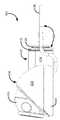
도 1a-1g는 하나의 실시예에 따르는 각각 카메라 헤드 및 케이블 조립체를 갖는 보안 카메라의 투시도, 정면도, 배면도, 우측방도, 좌측방도, 평면도, 및 저면도이다.
도 2는 카메라 헤드의 돔 커버가 제거된 보안 카메라의 우측방도이다.
도 3은 카메라 헤드의 돔 커버가 제거되고 카메라 헤드의 일부를 형성하는 아이볼 카메라의 후면 껍질도 제거된 보안 카메라의 우측방도이다.
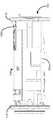
도 4a-4e는 모듈 하우징이 제거된 프로세싱 모듈의 우측방도, 좌측방도, 평면도, 저면도, 및 투시도이다.
도 5는 모듈 하우징 및 열 확산기가 없는 도 4a-4e의 프로세싱 모듈의 투시도이다.
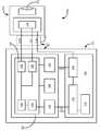
도 6은 보안 카메라의 블록도이다.
도 7a는 장착면에 설치된 보안 카메라를 보여주는 장착면의 측방 부분도이다.
도 7b는 또 다른 실시예에 따르는, 장착면에 보안 카메라를 장착하기 위한 방법을 도시하는 흐름도이다.In the accompanying drawings which illustrate one or more exemplary embodiments,
1A-1G are perspective, front view, back view, right view, left view, top view, and bottom view, respectively, of a security camera with a camera head and cable assembly in accordance with one embodiment.
2 is a right side view of a security camera in which a dome cover of a camera head is removed.
Figure 3 is a right-hand side view of a security camera with the rear shell removed of the eyeball camera, where the dome cover of the camera head is removed and forms part of the camera head.
Figures 4A-4E are the right side view, left side view, plan view, bottom view, and perspective view of the processing module with the module housing removed.
Figure 5 is a perspective view of the processing module of Figures 4A-4E without the module housing and heat spreader.
6 is a block diagram of a security camera.
7A is a side view of a mounting surface showing a security camera installed on the mounting surface.
7B is a flowchart illustrating a method for mounting a security camera on a mounting surface, according to another embodiment.
다음의 기재에서 방향 용어, 가령, "상부", "하부", "상향", "하향", "수직방향", 및 "횡방향"이 상대적 기준을 제공하기 위한 목적으로만 사용되고, 임의의 물품이 사용 중에 위치 설정될 방식 또는 조립체에 장착되거나 주변에 비해 장착될 방식에 대한 어떠한 한정사항을 암시하려는 것이 아니다.In the following description, it will be understood that directional terms are used only for the purpose of providing relative references, e.g., "top", "bottom", "upward", "downward", "vertical", and " Is not intended to imply any limitation as to the manner in which it will be positioned during use, or how it will be mounted to, or mounted relative to, the assembly.
보안 산업이 몇 가지 방식으로 카메라를 소형화하려 시도했다. 한 가지 방식은 카메라의 이미지 프로세싱 회로로부터 카메라의 전기-광학소자를 분리하는 것이 있다. 이는 비교적 부피가 클 수 있는 이미지 프로세싱 회로가, 비교적 작은 렌즈 및 이미지 센서를 포함하는 전기-광학소자로부터 원격으로 위치될 수 있다. 이미지 프로세싱 회로는 프로세싱 모듈 내에 담기고 전기-광학 소자는 프로세싱 모듈로부터 이격된 카메라 헤드 내에 담긴다. 따라서, 감시 대상에게 보이는 카메라의 일부분인 카메라 헤드는, 전기-광학소자 및 이미지 프로세싱 회로가 모두 카메라 헤드 내에 담긴 경우보다 더 작게 제작될 수 있다. 케이블이 프로세싱 모듈과 카메라 헤드를 연결하고, 카메라는 프로세싱 모듈을 통해 네트워크로 연결된다. 인터넷 프로토콜(IP) 카메라의 경우, 카메라는 IP 네트워크로 연결된다.The security industry has tried to miniaturize the camera in several ways. One approach is to separate the electro-optic element of the camera from the image processing circuitry of the camera. This allows relatively bulky image processing circuitry to be located remotely from an electro-optic element comprising a relatively small lens and image sensor. The image processing circuit is contained within the processing module and the electro-optic element is contained within a camera head spaced from the processing module. Thus, the camera head, which is part of the camera visible to the monitored object, can be made smaller than when both the electro-optical element and the image processing circuit are contained within the camera head. A cable connects the processing module to the camera head, and the camera is connected to the network through a processing module. In the case of an Internet Protocol (IP) camera, the camera is connected to an IP network.
전기-광학소자와 이미지 프로세싱 회로를 분리함으로써, 비교적 작은 카메라 헤드의 제조를 가능하게 하면서, 카메라를 설치 중인 기술자가 비교적 부피가 큰 프로세싱 모듈을 다룰 필요가 있다. 프로세싱 모듈은 설치 후 카메라 헤드에 매달려 있거나 차후 카메라 헤드에 의해 덮일 수 있는 구멍에 들어맞기에 지나치게 크고 무겁기 때문에, 기술자가 카메라 헤드와 프로세싱 모듈 모두를 하나 이상의 장착면에 장착할 정도로 종래의 프로세싱 모듈은 크다. 따라서 기술자는 모든 전자소자 및 광학 설비가 카메라 헤드 내에 담기는 일체형 카메라를 설치할 수 있는 방식과 동일하게, 개별 프로세싱 모듈과 카메라 헤드를 갖는 카메라를 설치할 수 없다. 일체형 카메라의 경우, 기술자는 단순하게 카메라 헤드를 장착면에 장착하고 카메라 헤드를 네트워크에 연결할 필요만 있으며, 카메라가 IP 카메라인 경우, 상기 네트워크는 카메라에 전력을 공급하기 위해서뿐 아니라 통신을 위해서도 사용된다. 이와 달리, 개별 프로세싱 모듈 및 카메라 헤드를 갖는 카메라를 설치하기 위해, 기술자는 프로세싱 모듈을 장착하기 위한 은닉된 위치를 식별하고, 프로세싱 모듈과 카메라 헤드를 개별적으로 장착하고, 카메라 헤드를 프로세싱 모듈에 연결하며, 그 후 프로세싱 모듈을 IP 네트워크에 연결한다.By separating the electro-optic element and the image processing circuitry, it is necessary for the technician installing the camera to handle relatively bulky processing modules, while enabling the manufacture of relatively small camera heads. Because the processing module is too large and heavy to fit into the hole that can be covered by the camera head or later hanging on the camera head after installation, the conventional processing module is so large that the technician mounts both the camera head and the processing module on one or more mounting surfaces Big. Therefore, the technician can not install a camera having a separate processing module and a camera head in the same manner as all the electronic elements and optical equipments can be installed in an integrated camera which is contained in the camera head. In the case of an integral camera, the technician simply needs to mount the camera head on the mounting surface and connect the camera head to the network, and if the camera is an IP camera, the network may be used for powering the camera as well as for communication do. Alternatively, to install the camera with the individual processing module and the camera head, the technician identifies the hidden location for mounting the processing module, separately mounts the processing module and the camera head, connects the camera head to the processing module And then connects the processing module to the IP network.
본 발명은 케이블에 의해 연결된 개별 프로세싱 모듈과 카메라 헤드를 포함하는 보안 카메라의 실시예에 관한 것인데, 여기서, 기술자가 카메라를 장착할 때 프로세싱 모듈과 카메라 헤드 모두를 장착할 필요가 없도록 프로세싱 모듈이 작고 가볍다. 기술자는 단순히 개구부를 뚫고, 프로세싱 모듈을 네트워크에 연결하며, 상기 개구부를 통해 프로세싱 모듈을 삽입하고, 카메라 헤드를 장착면에 그리고 개구부 위에 장착함으로써, 카메라 헤드를 이용해 개구부를 덮는다. 프로세싱 모듈은 프로세싱 모듈과 카메라 헤드를 연결하는 케이블에 의해 카메라 헤드로부터 자유롭게 매달리기에 충분히 가볍다. 기술자가 모든 전자소자 및 광소자가 카메라 헤드 내에 담긴 카메라를 설치할 때 하는 것과 유사하게, 카메라를 간단하게 네트워크에 연결하고 카메라 헤드를 장착면에 장착할 수 있기 때문에 프로세싱 모듈은 기술자에게 효과적으로 투명하다. 도시된 카메라는 IP 카메라이지만, 대안적 실시예(도시되지 않음)는 비-IP 카메라, 가령, 아날로그 카메라를 포함한다.The present invention relates to an embodiment of a security camera comprising a separate processing module and a camera head connected by a cable wherein the processing module is small so that the technician does not need to mount both the processing module and the camera head when the camera is mounted light. The technician simply covers the opening with a camera head by drilling through the opening, connecting the processing module to the network, inserting the processing module through the opening, and mounting the camera head onto the mounting surface and over the opening. The processing module is light enough to hang freely from the camera head by a cable connecting the processing module and the camera head. The processing module is effectively transparent to the technician, as the technician can simply connect the camera to the network and mount the camera head to the mounting surface, similar to what every electronic device and photonic device installs in a camera head camera. Although the camera shown is an IP camera, an alternative embodiment (not shown) includes a non-IP camera, e.g., an analog camera.
도 1a-1g를 다시 참조하면, 하나의 실시예에 따르는 각각 카메라 헤드(104) 및 케이블 조립체(102)를 갖는 보안 카메라(100)의 투시도, 정면도, 배면도, 우측방도, 좌측방도, 평면도, 및 저면도가 나타난다. 케이블 조립체(102)는 프로세싱 모듈(103) 및 프로세싱 모듈(103)과 카메라 헤드(104)를 연결하는 케이블(106)을 포함한다. 본 명세서에 도시된 카메라(100)는 돔 카메라(dome camera)이지만, 대안적 실시예(도시되지 않음)에서, 카메라(100)는 또 다른 유형의 카메라, 가령, 박스 카메라, 핀홀 카메라, 또는 총알형 카메라일 수 있다.1A-1G, a perspective view, a front view, a rear view, a right view, a left view, a plan view, and a perspective view of a
카메라 헤드(104)는 돔 베이스(dome base)(124)를 포함하며, 상기 돔 베이스 상에 돔 커버(108)가 부착된다. 돔 커버(108) 및 베이스(124) 내 개구부는 베이스(124) 상에 놓이는 아이볼 카메라(eyeball camera)(110)가 돔 커버(108)의 정면에서 돌출되도록 한다. 아이볼 카메라(110)의 정면은 카메라(100)의 렌즈(112)이다. 상기 렌즈(112)는 아이볼 카메라(110) 내에 장착되는 이미지 센서(126)(도 3에 도시됨)로 빛을 포커싱한다. 도 3을 참조하여 이하에서 더 상세히 언급되는 바와 같이, 극세-동축 케이블(micro-coaxial cable)(106)은 아이볼 카메라(110)를 프로세싱 모듈(103)로 연결하며, 상기 프로세싱 모듈은 이미지 센서(126)가 출력하는 비디오 신호를 프로세싱한다.The
도 1a-1g에서, 프로세싱 모듈(103)의 외부만 가시적이다. 프로세싱 모듈(103)의 상부, 하부, 좌측 및 우측부가 모듈 하우징(114)에 의해 정의되며, 전단부 및 후단부 플레이트(115)는 프로세싱 모듈(103)의 단부를 캡핑한다. 상기 극세-동축 케이블(106)은 프로세싱 모듈(103)의 후단부 플레이트(115)로 연결된다. 방수 그로밋(waterproof grommet)(122)은 프로세싱 모듈(103)에서 종료하고 후단부 플레이트(115) 내부로 나사 고정되는 극세-동축 케이블(106)의 단부를 둘러쌈으로써 수밀 밀봉(water tight seal)을 보장할 수 있다. 프로세싱 모듈(103)의 전단부 플레이트(115)는 카메라(100)를 IP 네트워크로 연결하는 RJ45 플러그를 수용하기 위해 RJ45(이더넷) 잭(118)의 형태를 갖는 네트워크 잭을 가진다. 도 6과 관련하여 이하에서 더 상세히 설명되겠지만, RJ45 잭을 통해 카메라(100)에 전력을 공급하기 위해 파워 오버 이더넷(PoE) 기술이 사용된다. 연결 및 링크 상태를 나타내는 한 쌍의 LED(120) 및 메모리 카드 슬롯(116)은 전단부 플레이트(115) 상에 나타난다.1A-1G, only the exterior of the
도 2 및 3을 참조하면, 카메라(100)의 우측방도가 나타난다. 더 구체적으로, 도 2는 돔 커버(108)가 제거된 카메라(100)의 우측방도를 도시하며, 도 3은 돔 커버(108)가 제거되고 아이볼 카메라(110)의 후방 껍질이 제거되어, 아이볼 카메라(110) 내에 담긴 회로가 드러난 카메라의 우측방도를 도시한다. 아이볼 카메라(110) 내부에 이미지 센서(126)로 연결되는 렌즈 장착부(128)가 존재한다. 극세-동축 케이블(106)은, 극세-동축 케이블(106)을 프로세싱 모듈(103)로 연결하도록 사용되기도 하는 I-PEX 20373-시리즈 커넥터를 통해 이미지 센서(126)로 전기적으로 연결된다. 이미지 센서는 MIPITM 프로토콜을 이용하는 극세-동축 케이블(106)을 따르는 고속 직렬 데이터 스트림을 출력하는 AptinaTM AR0330 센서이다. 상기 극세-동축 케이블(106)은 열가소성 폴리우레탄으로 피복되며 고속 직렬 통신을 촉진하기 위해 14개의 도선(conductor)을 포함한다. 대안적 실시예(도시되지 않음)에서, 프로세싱 모듈(103)과 카메라 헤드(104) 간 통신이 이미지 센서(126)가 출력하는 비디오 신호를 전송하기에 충분히 신속하게 수행될 수 있는 한, 상이한 개수의 도선 또는 상이한 피복 물질을 이용해 극세-동축 케이블(106)이 제작될 수 있다.Referring to Figs. 2 and 3, the right side view of the
도 6은 카메라(100)의 블록도를 도시한다. 렌즈(112) 및 이미지 센서(126)는 카메라 헤드(104) 내에 위치하는 것으로 나타난다. 프로세싱 모듈(103)은 프로세서(138), 이미지 신호 프로세서(ISP)(126), 미디어 액세스 제어기(MAC)(144), 및 I2C 인터페이스(142)를 포함하는 시스템 온 어 칩(SoC)(136)을 포함한다. 상기 프로세서(138)는 ISP(126), MAC(144), 및 I2C 인터페이스(142) 각각과 통신한다. 도 6은 프로세싱 모듈(103)이 카메라 헤드(104)로 전기적으로 연결되는 3개의 서로 다른 방식을 도시한다. 앞서 언급된 바와 같이, 첫 번째는 ISP(126)는 MIPITM 프로토콜을 통한 이미지 센서(126)와의 통신이고, 두 번째는 I2C 인터페이스(142)는 I2C 프로토콜을 이용해 이미지 센서(126)와 통신하는 것이며, 세 번째는 카메라 헤드(104)에 프로세싱 모듈(103)로부터의 3.3V 전력 공급 라인에 의해 전력이 공급되는 것이다. 이들 세 가지 형태의 전기 결합이 극세-동축 케이블(106)을 통해 발생한다. I2C 인터페이스(142)가 카메라 파라미터, 가령, 이득, 노출, 및 프레임 레이트를 제어하도록 사용된다.6 shows a block diagram of the
SoC(136)는 부분을 포함하고 이미지 프로세싱 인쇄 회로 기판(PCB)(130) 상에 레이아웃된 카메라(100)의 이미지 프로세싱 회로의 일부를 포함한다. SoC(136)에 추가로, 이미지 프로세싱 PCB(130) 상에 MAC(144)과 통신 가능한 물리 계층 집적 회로(PHY)(146)가 존재하고, 비휘발성이고 SoC(136)가 작업, 가령, 이미지 프로세싱을 수행하기 위한 스테이트먼트 및 명령을 저장하는 예시적 비-일시적 컴퓨터 판독형 매체인 플래시 메모리(148), 및 또 다른 예시적 비-전이적 컴퓨터 판독형 매체이지만 휘발성이며 SoC(136)가 정보를 일시적으로 저장하기 위해 사용하며 작업을 수행하는 동안 작업 공간으로서 사용되는 RAM(150)이 존재한다.The
또한 프로세싱 모듈(103) 내에, 전력 PCB(132)의 일부를 포함하고 PCB 상에 레이아웃되는 전력 회로가 존재한다. 전력 PCB(132) 상에 RJ45 잭(118), RJ45 잭(118) 및 PHY(146)과 통신하는 이더넷 마그네틱(Ethernet magnetics)(152), 및 이더넷 마그네틱스(152)에 전기적으로 연결되며 3.3V 신호를 출력하여 이미지 프로세싱 회로 및 카메라 헤드(104)에 전력을 공급하는 DC-DC 변환기(154)가 존재한다. 대안적 실시예(도시되지 않음)에서, 카메라(100)가 예를 들어 AC 어댑터 또는 배터리를 이용해 전력이 공급될 수 있지만, PoE 기술을 이용해 카메라(100)에 전력이 공급된다.Also within the
PCB(130, 132) 상에 전력 회로를 배치함으로써 이미지 프로세싱 회로로부터 전력 회로를 분리함으로써, 프로세싱 모듈(103)의 치수가 비교적 작아질 수 있는데, 예를 들어, 도시된 프로세싱 모듈(103)은 대략 24mm (0.94 인치) × 28mm (1.1 인치) × 57mm (2.2 인치)이다. 모든 이미지 프로세싱 및 전력 회로가 동일한 PCB 상에 있는 경우, 프로세싱 모듈(103)은 대략 2배 넓거나 길 것이다.By separating the power circuit from the image processing circuitry by placing the power circuitry on the
프로세싱 모듈(103)의 설계 동안 발생하는 한 가지 문제는, 구성요소가 과열되는 것을 막기 위해 충분한 열 소산을 보장하는 것이며, 도시된 실시예에서, 프로세싱 모듈(103)은 모든 회로 구성요소의 최대 추천되는 동작 온도 내에서 동작하도록 설계되며, 구체적으로 SoC(136)가 50℃의 주변 온도에서 동작하도록 설계된다. 이미지 프로세싱 PCB(130) 상의 SoC(136), 및 정도는 적어도, 전력 PCB(132) 상의 DC-DC 변환기(154)가 동작 동안 PCB(130,132) 상의 다른 회로 구성요소에 비교해서 비교적 많은 양의 열을 발생시킨다. 개별적인 PCB(130,132) 상에 이들을 유지하는 것이 프로세싱 모듈(103)을 통해 열을 확산시키는 데 도움이 되며 프로세싱 모듈(103)이 수락 가능한 동작 온도로 프로세싱 모듈(103)을 유지하는 데 도움이 된다.One problem that arises during the design of the
도 4a-4e는 모듈 하우징(114)이 제거된 프로세싱 모듈(103)의 우측방도, 좌측방도, 평면도, 저면도, 및 투시도이다. 이들 도면은 PCB(130, 132)가 분리되는 특정 방식을 나타내는데, 즉, 이들은 서로 대향하며 평행하게 이격되어 있다. 특히, 도시된 실시예에서, PCB(130, 132)는 동일하게 크기가 정해지며 PCB(130, 132) 각각의 평면 표면이 서로 대향하도록 위치함으로써, PCB(130, 132) 중 한 PCB의 평면 표면으로부터 수직으로 뻗어 있는 선이 PCB(130,132) 중 다른 한 PCB의 평면 표면에 수직으로 교차할 수 있다. 도시된 프로세싱 모듈(103)이 서로 대향하면서 평행한 PCB(130, 132) 및 크기가 동일한 2개의 PCB(130, 132)를 도시하며, 대안적 실시예(도시되지 않음)에서, PCB(130, 132)는 서로 다르게 배열 및 크기 중 적어도 하나를 가질 수 있다. 예를 들어, PCB(130, 132)는 서로에 평행하지 않게 이격될 수 있으며, 이들은 서로 다른 치수 또는 표면적을 가질 수 있거나, 전체적으로 겹치지 않을 수 있다.Figs. 4A-4E are the right side view, left side view, plan view, bottom view, and perspective view of the
또한, 도 4a-4e는 열 소산을 증가시키기 위해 프로세싱 모듈(103)이 열 확산기를 포함하는 방식을 도시한다. 상기 열 확산기(134)는 모듈 하우징(114)의 상부의 아랫면에 인접한 SoC(136)의 상부에 부착된다. 상기 열 확산기(134)는 프로세싱 모듈(103)을 따라 종방향으로 이미지 프로세싱 PCB(130)의 상부 위에 뻗어 있는 평면 부재(planar member)(135) 및 상기 평면 부재(135)의 대향하는 에지에 연결되며 이미지 프로세싱 PCB(130)의 좌측 에지 및 우측 에지를 지나 하향으로 뻗어 있는 2개의 윙 부재(wing member)(137)를 포함한다. 윙 부재(137)는 2개의 PCB(130,132) 사이의 공간에서 종료한다. 도 5는 모듈 하우징(114)이 없고 열 확산기(134)가 없는 도 4a-4e의 프로세싱 모듈의 투시도이며, 열 확산기(134)가 부착된 SoC(136)를 도시한다. 도 4a-4e에서, 윙 부재(137)는 곡선형이지만, 대안적 실시예(도시되지 않음)에서, 윙 부재(137)는 평면일 수 있다. 마찬가지로, 대안적 실시예(도시되지 않음)에서, 평면 부재(135)는 비-평면 부재로 교체될 수 있다.4A-4E also show how the
도 7a 및 7b를 참조하면, 장착면(160)에 설치되는 카메라(100)를 보여주는 장착면(160)의 측방 부분도 및 보안 카메라를 장착면(160)에 장착하기 위한 예시적 방법(700)을 나타내는 흐름도가 도시된다. 카메라(100)를 설치하기 위해, 기술자는 방법(700)을 시작하고(블록(702)) 장착면에 개구부(160)를 뚫는다(블록(704)). 상기 개구부(160)는 케이블 조립체(102)가 통과할 수 있고 돔 베이스(124)에 의해 덮일 수 있도록 크기가 정해진다. 그 후 기술자는 프로세서 모듈(103)을 네트워크로 연결하고(블록(706)), 도 7a에서, RJ45 플러그가 프로세싱 모듈(103)의 외부 상에서 가시적인 부트(158)로 피복된다. 카메라(100)에 비디오 신호를 전송할 수 있는 능력을 제공하는 것에 추가로, 카메라(100)를 네트워크로 연결하는 것이 또한 카메라(100)에 전력을 공급한다. 카메라(100)를 네트워크에 연결한 후, 기술자는 케이블 조립체(102)의 나머지 부분과 함께 프로세서 모듈(103)을, 개구부(156)를 통해 삽입하고(블록(708)), 카메라 헤드(104)를 장착면(160) 상으로 그리고 개구부(156) 위에 장착함으로써 상기 개구부를 덮음으로써, 카메라 헤드가 개구부(156)를 덮을 수 있다(블록(710)). 카메라 헤드(104)가 장착면(160)에 고정된 후, 장착 프로세스가 완료된다(블록(712)).7A and 7B are a side view of the mounting
설치 프로세스는 종래의 돔 카메라를 설치하도록 사용되는 프로세스와 실질적으로 유사한데, 여기서, 모든 전자소자 및 광소자가 카메라 헤드 내에 담기며, 여기서 카메라 헤드(104)만 장착된다. 따라서 프로세싱 모듈(103)이 기술자에게 기능적으로 투명하며, 기술자는 프로세싱 모듈(103)을 개별적으로 장착할 필요 없이 도시된 소형화된 돔 카메라(100)를 설치할 수 있다. 비교적 부피가 크고 무거운 프로세싱 모듈을 갖는 대안적 카메라에서, 프로세싱 모듈의 가외적 크기가 열 소산을 훨씬 덜하게 만들면서, 프로세싱 모듈이 카메라 헤드로부터 따로 장착될 것을 요구하며 프로세싱 모듈을 카메라 헤드에 의해 덮일 수 있는 개구부에 끼워 맞추는 것이 실현불가능하게 될 수 있다.The installation process is substantially similar to the process used to install a conventional dome camera, where all electronic elements and optical elements are contained within the camera head, where only the
도 7a에서, 장착면(160)은 방의 모서리 근방의 천장의 일부분이며, 프로세싱 모듈(103)은 상기 천장에 가까운 벽에 걸려 있다. 상기 프로세싱 모듈(103)은 이의 작은 크기 때문에 비교적 가벼울 수 있고, 이로 인해 카메라(100)가 장착될 때, 프로세싱 모듈(103)이 카메라 헤드(104)에 의해서만 영구적으로 지지될 수 있으며, 도시된 실시예에서, 프로세싱 모듈(103)은 대략 36g(1.3온스(ounce))의 중량를 갖고, 카메라(100)의 총 중량는 대략 75g(2.6온스)이다. 도시된 실시예에서, 그로밋(122)은 극세-동축 케이블(106)과 프로세싱 모듈(103) 간 연결을 보강하며, 이로 인해, 프로세싱 모듈(103)이 더 잘 카메라 헤드(104)에 매달릴 수 있게 된다. 대안적 실시예(도시되지 않음)에서, 극세-동축 케이블(106)과 카메라 헤드(104) 및 프로세싱 모듈(103) 중 하나 또는 둘 모두 간의 연결이 여러 다른 방식으로 보강될 수 있는데, 가령, 극세-동축 케이블(106) 상의 피복의 탄성을 증가시킴으로써 또는 극세-동축 케이블(106)을 카메라 헤드(104) 및 프로세싱 모듈(103)에 고정하기 위해 사용되는 패스너(fastener)의 개수를 증가시킴으로써, 보강될 수 있다. 덧붙여, 대안적 실시예(도시되지 않음)에서, 프로세싱 모듈(103)이 카메라 헤드(104) 뒤에서 장착면(160)에 또는 감시 대상의 시야에서 벗어난 그 밖의 다른 일부 표면에 고정될 수 있는데, 예를 들면, 프로세싱 모듈(103)의 하나의 면이 장착면(160) 뒤에 제위치로 고정하기 위한 접착제를 가질 수 있다. 또 다른 대안적 실시예(도시되지 않음)에서, 프로세싱 모듈(103)은 카메라 헤드(104)로부터 영구적으로 자유롭게 매달리기에 지나치게 무거울 수 있으며, 이 경우, 프로세싱 모듈(103)은 사용 중에 지지를 위해 표면에 부착될 수 있거나 평면 표면, 가령, 카메라 헤드(104)가 고정되는 면에 대향하는 장착면(160)의 면 상에 상에 놓일 수 있다.7A, the mounting
앞서 언급된 바와 같이, 모든 이미지 프로세싱 및 전력 회로가 동일한 PCB 상에 있는 경우, 프로세싱 모듈(103)은 대략 두 배 더 넓거나 길 것이다. 따라서 이러한 더 큰 프로세싱 모듈(103)을 수용하도록 만들어질 필요가 있는 개구부(156)를 덮기 위해, 카메라 헤드(104)는 크기가 증가되어야 할 것이며, 이로 인해, 카메라 헤드(104)는 감시 대상에게 발견되기 더 쉬워질 것이다.As noted above, if all of the image processing and power circuitry are on the same PCB, the
도시된 실시예에서, 극세-동축 케이블(106)은 프로세서 모듈(103)에 영구적으로 연결되지만(즉, 극세-동축 케이블이 카메라(100)의 정상 이용 동안 프로세서 모듈(103)로부터 제거되도록 설계되지 않음), 대안적 실시예(도시되지 않음)에서, 반드시 그렇지 않을 수 있다. 예를 들어, 대안적 실시예에서, 극세-동축 케이블(106)은, 예를 들어, 플러그 및 소켓 연결을 이용해 프로세싱 모듈(103)로 탈착 가능하게 연결될 수 있다.Although the
앞서 언급된 실시예에서 SoC(136)가 사용되더라도, 대안적 실시예(도시되지 않음)에서, SoC(136)가, 예를 들어, 마이크로프로세서, 마이크로제어기, 프로그래머블 로직 제어기, 필드 프로그래머블 게이트 어레이, 또는 주문형 집적 회로로 대체될 수 있다. 컴퓨터 판독형 매체의 예시는 비-일시적(non-transitory) 디스크 기반 매체, 가령, CD-ROM 및 DVD, 자기 매체, 가령, 하드 드라이브 및 그 밖의 다른 형태의 자기 디스크 저장소, 및 반도체 기반 매체, 가령, 플래시 매체(flash media), 랜덤 액세스 메모리(random access memory), 및 리드 온리 메모리(read only memory)가 있다.In an alternative embodiment (not shown),
본 명세서에서 언급된 임의의 양태 또는 실시예의 임의의 부분이 본 명세서에 언급된 다른 임의의 양태 또는 실시예의 임의의 부분과 함께 구현되거나 조합될 수 있다.Any aspect or embodiment of any aspect mentioned herein may be implemented or combined with any other aspect or any portion of the embodiments mentioned herein.
도 7b는 예시적 방법의 흐름도이다. 흐름도에 도시된 블록들 중 일부가 기재된 것과 다른 순서로 수행될 수 있다. 또한 흐름도에 기재된 모든 블록이 수행될 필요가 있는 것은 아니며, 추가 블록이 추가될 수 있고, 도시된 블록들 중 일부가 다른 블록으로 치환될 수 있음이 자명할 것이다.7B is a flow diagram of an exemplary method. Some of the blocks shown in the flowchart may be performed in a different order than described. It will also be appreciated that not all of the blocks described in the flowchart need be performed, additional blocks may be added, and some of the illustrated blocks may be replaced by other blocks.
편의상, 상기의 예시적 실시예는 다양한 상호 연결된 기능 블록으로 기술된다. 그러나 이는 필수는 아니며, 이들 기능 블록이 불명확한 경계를 갖는 하나의 단일 로직 장치, 프로그램, 또는 동작으로 응집되는 경우도 존재할 수 있다. 어느 경우라도, 기능 블록은 단독으로, 또는 그 밖의 다른 하드웨어 또는 소프트웨어와 조합되어 구현될 수 있다.For convenience, the above exemplary embodiments are described as various interconnected functional blocks. However, this is not essential, and there may be cases where these functional blocks cohere with one single logical device, program, or operation with indefinite bounds. In either case, the functional blocks may be implemented alone, or in combination with other hardware or software.
앞서 특정 실시예가 기재되었지만, 그 밖의 다른 실시예가 가능하고 본 명세서에 포함되는 것으로 의도됨이 이해되어야 한다. 해당 분야의 통상의 기술자라면 도시되지 않더라도 앞서 기재된 실시예의 수정 및 조절이 가능함을 알 것이다.While specific embodiments have been described above, it should be understood that other and further embodiments are possible and are intended to be included herein. Those skilled in the art will appreciate that modifications and adjustments to the embodiments described above are possible, even if not shown.
Claims (20)
Translated fromKorean(a) 렌즈 및 이미지 센서를 포함하는 카메라 헤드, 및
(b) 케이블 조립체
를 포함하며, 상기 케이블 조립체는
(ⅰ) 카메라 헤드로 연결되는 케이블, 및
(ⅱ) 상기 케이블을 통해 카메라 헤드로 연결되는 프로세싱 모듈을 포함하며, 상기 프로세싱 모듈은
(1) 이미지 센서와 통신 가능한 이미지 프로세싱 회로, 및
(2) 상기 이미지 프로세싱 회로 및 카메라 헤드와 전기적으로 연결된 전력 회로를 포함하며, 상기 프로세싱 모듈은, 카메라 헤드가 장착면에 장착될 때 상기 카메라 헤드에 의해 덮일 수 있는 장착면 내 개구부에 끼워 맞춤되도록 크기가 정해지는, 보안 카메라.A security camera comprising:
(a) a camera head including a lens and an image sensor, and
(b) Cable assembly
, Wherein the cable assembly
(I) a cable connected to the camera head, and
(Ii) a processing module coupled to the camera head through the cable, the processing module
(1) an image processing circuit capable of communicating with an image sensor, and
(2) a power circuit electrically connected to the image processing circuit and the camera head, the processing module being adapted to be fitted to an opening in the mounting surface that can be covered by the camera head when the camera head is mounted on the mounting surface A security camera whose size is fixed.
(a) 상기 프로세싱 모듈을 따라 종방향으로 그리고 이미지 프로세싱 PCB 위에 뻗어 있는 평면 부재, 및
(b) 상기 평면 부재의 서로 대향하는 에지들에 연결되며 이미지 프로세싱 PCB의 측부 에지를 지나 뻗어 있는 2개의 윙 부재
를 포함하는, 보안 카메라.7. The apparatus of claim 6, wherein the heat spreader
(a) a planar member extending longitudinally along the processing module and onto the image processing PCB, and
(b) two wing members connected to opposing edges of the planar member and extending beyond a side edge of the image processing PCB,
And a security camera.
(a) 렌즈 및 이미지 센서를 포함하는 카메라 헤드, 및
(b) 케이블 조립체
를 포함하고, 상기 케이블 조립체는
(ⅰ) 카메라 헤드에 연결된 케이블, 및
(ⅱ) 케이블을 통해 카메라 헤드로 연결된 프로세싱 모듈을 포함하며, 상기 프로세싱 모듈은
(1) 이미지 센서와 통신 가능하며 이미지 프로세싱 PCB(printed circuit board)를 포함하는 이미지 프로세싱 회로, 및
(2) 상기 이미지 프로세싱 회로 및 카메라 헤드와 전기적으로 연결되며 전력 PCB를 포함하는 전력 회로를 포함하며,
상기 이미지 프로세싱 PCB 및 전력 PCB는 서로 대향하며 평행하게 위치하며, 상기 프로세싱 모듈은, 카메라 헤드가 장착면에 장착될 때 상기 카메라 헤드에 의해 덮일 수 있는 장착면 내 개구부에 끼워 맞춤되도록 크기가 정해지는, 보안 카메라.A security camera comprising:
(a) a camera head including a lens and an image sensor, and
(b) Cable assembly
The cable assembly comprising:
(I) a cable connected to the camera head, and
(Ii) a processing module coupled to the camera head via a cable, the processing module
(1) an image processing circuit communicable with the image sensor and including an image processing PCB (printed circuit board); and
(2) a power circuit electrically connected to the image processing circuit and the camera head and including a power PCB,
Wherein the image processing PCB and the power PCB are opposed and parallel to each other and the processing module is sized to fit into an opening in the mounting surface that can be covered by the camera head when the camera head is mounted on the mounting surface , Security camera.
(a) 장착면에 개구부를 뚫는 단계 - 상기 개구부는, 카메라 헤드가 장착면에 고정될 때 케이블 조립체가 통과할 수 있고 카메라 헤드에 의해 덮일 수 있도록 크기가 정해짐 - ,
(b) 상기 카메라를 케이블 조립체를 통해 네트워크에 연결하는 단계 - 상기 케이블 조립체는 (ⅰ) 카메라 헤드에 연결된 케이블, 및 (ⅱ) 케이블을 통해 카메라 헤드로 연결된 프로세싱 모듈을 포함함 - ,
(c) 상기 개구부를 통해 케이블 조립체를 삽입하는 단계, 및
(d) 상기 카메라 헤드가 개구부를 덮도록 카메라 헤드를 장착면에 고정하는 단계
를 포함하는, 보안 카메라를 장착하기 위한 방법.A method for mounting a security camera comprising a camera head and a cable assembly, the method comprising:
(a) drilling an opening in a mounting surface, the opening being sized to allow the cable assembly to pass through and be covered by the camera head when the camera head is secured to the mounting surface;
(b) connecting the camera to a network through a cable assembly, the cable assembly comprising: (i) a cable connected to the camera head; and (ii) a processing module coupled to the camera head via a cable,
(c) inserting the cable assembly through the opening, and
(d) fixing the camera head to the mounting surface so that the camera head covers the opening
Gt; a < / RTI > security camera.
(a) 카메라 헤드의 이미지 센서 포함 부분과 통신 가능한 이미지 프로세싱 회로 - 상기 이미지 프로세싱 회로는 이미지 프로세싱 PCB(printed circuit board)를 포함함 - , 및
(b) 이미지 프로세싱 회로 및 카메라 헤드로 전기적으로 연결되는 전력 회로 - 전력 회로는 전력 PCB를 포함하고, 이미지 프로세싱 PCB 및 전력 PCB 모두 프로세싱 모듈 내에 하우징됨 -
를 포함하는, 보안 카메라를 장착하기 위한 방법.16. The system of claim 14 or 15, wherein the processing module
(a) an image processing circuit capable of communicating with an image sensor-containing portion of a camera head, the image processing circuit comprising an image processing printed circuit board
(b) a power circuit electrically connected to the image processing circuit and the camera head, the power circuit comprising a power PCB, both the image processing PCB and the power PCB being housed in a processing module,
Gt; a < / RTI > security camera.
16. A method according to claim 14 or 15, wherein the cable comprises a coated micro-coaxial cable having a plurality of conductors.
Applications Claiming Priority (1)
| Application Number | Priority Date | Filing Date | Title |
|---|---|---|---|
| PCT/CA2013/050334WO2014176659A1 (en) | 2013-04-30 | 2013-04-30 | Security camera having a cable assembly with an integrated processing module |
Publications (2)
| Publication Number | Publication Date |
|---|---|
| KR20160006186A KR20160006186A (en) | 2016-01-18 |
| KR101635337B1true KR101635337B1 (en) | 2016-06-30 |
Family
ID=51843005
Family Applications (1)
| Application Number | Title | Priority Date | Filing Date |
|---|---|---|---|
| KR1020157033629AActiveKR101635337B1 (en) | 2013-04-30 | 2013-04-30 | Security camera having a cable assembly with an integrated processing module |
Country Status (12)
| Country | Link |
|---|---|
| EP (1) | EP2992519B2 (en) |
| JP (1) | JP6005324B2 (en) |
| KR (1) | KR101635337B1 (en) |
| CN (1) | CN105359196B (en) |
| AU (1) | AU2013388664B2 (en) |
| BR (1) | BR112015027277B8 (en) |
| CA (1) | CA2910258C (en) |
| IL (1) | IL242274A (en) |
| MX (1) | MX347950B (en) |
| SG (1) | SG11201508947VA (en) |
| WO (1) | WO2014176659A1 (en) |
| ZA (1) | ZA201508736B (en) |
Families Citing this family (3)
| Publication number | Priority date | Publication date | Assignee | Title |
|---|---|---|---|---|
| US9167137B2 (en) | 2013-04-30 | 2015-10-20 | Avigilon Corporation | Security camera having a cable assembly with an integrated processing module |
| CN111541882B (en)* | 2020-06-05 | 2024-07-23 | 江苏大橡木集团有限公司 | Microorganism monitoring system device for clean environment |
| CN112947167B (en)* | 2021-02-02 | 2022-06-21 | 傅剑峰 | Security monitoring device capable of realizing self-protection according to environment change |
Citations (1)
| Publication number | Priority date | Publication date | Assignee | Title |
|---|---|---|---|---|
| US20080136915A1 (en) | 2006-12-06 | 2008-06-12 | Sony Corporation | Wall mount camera |
Family Cites Families (25)
| Publication number | Priority date | Publication date | Assignee | Title |
|---|---|---|---|---|
| US4746990A (en)* | 1985-12-02 | 1988-05-24 | Olympus Optical Co., Ltd. | Detachable unit electronic camera |
| US5418567A (en)* | 1993-01-29 | 1995-05-23 | Bayport Controls, Inc. | Surveillance camera system |
| JPH07162723A (en)* | 1993-12-10 | 1995-06-23 | Atsumi Electron Corp Ltd | Monitoring camera |
| JP3247229B2 (en)* | 1993-12-17 | 2002-01-15 | 株式会社日立国際電気 | Infrared television camera |
| US5864365A (en)* | 1996-01-26 | 1999-01-26 | Kaman Sciences Corporation | Environmentally controlled camera housing assembly |
| US6078359A (en) | 1996-07-15 | 2000-06-20 | The Regents Of The University Of California | Vacuum compatible miniature CCD camera head |
| US6392698B1 (en)* | 1996-12-06 | 2002-05-21 | Canon Kabushiki Kaisha | Camera head-detachable image sensing apparatus, image processing apparatus, and image sensing system constituted therewith |
| CA2303525A1 (en)* | 2000-03-30 | 2001-09-30 | Silent Witness Enterprises Ltd. | Heat management for enclosed video cameras |
| JP3086990U (en)* | 2001-12-27 | 2002-07-05 | 有限会社ホームワーカー | Surveillance camera |
| US6896423B2 (en)* | 2002-09-20 | 2005-05-24 | Pelco | Camera mounting enclosure and method of installation |
| JP4273941B2 (en)* | 2003-11-25 | 2009-06-03 | パナソニック電工株式会社 | Security sensor |
| US7742077B2 (en) | 2004-02-19 | 2010-06-22 | Robert Bosch Gmbh | Image stabilization system and method for a video camera |
| US7621680B2 (en)* | 2005-12-06 | 2009-11-24 | Robert Bosch Gmbh | In-ceiling surveillance housing |
| JP4640267B2 (en)* | 2006-06-13 | 2011-03-02 | パナソニック株式会社 | Wiring equipment and surveillance camera device |
| ITVI20070213A1 (en)* | 2007-08-02 | 2009-02-03 | Tekno System Spa | PROTECTIVE HOUSING FOR CAMERAS FOR THE TRANSMISSION OF THE VIDEO SIGNAL IN DIGITAL FORMAT. |
| US8120656B2 (en)* | 2007-09-26 | 2012-02-21 | Shih-Ming Hwang | Assembly module having a video transmission element |
| WO2009046513A1 (en) | 2007-10-09 | 2009-04-16 | Tony Mayer | Camera housing heatsink bracket system |
| ES2339066T3 (en)† | 2007-11-29 | 2010-05-14 | Axis Ab | NETWORK CAMERA |
| US20090315990A1 (en) | 2008-06-19 | 2009-12-24 | Honeywell International Inc. | Apparatus for surveillance camera system |
| JP5347901B2 (en)* | 2009-10-21 | 2013-11-20 | ソニー株式会社 | Monitoring device |
| JP2011207339A (en)* | 2010-03-30 | 2011-10-20 | Beat Sonic:Kk | Fixture for in-vehicle accessory, and mounting method for the in-vehicle accessory by the fixture |
| JP2012015995A (en)* | 2010-05-31 | 2012-01-19 | Fujitsu Component Ltd | Camera module and manufacturing method of the same |
| JP2012118151A (en)* | 2010-11-30 | 2012-06-21 | Canon Inc | Imaging apparatus |
| KR101187916B1 (en) | 2011-01-24 | 2012-10-05 | 삼성테크윈 주식회사 | Electronic apparatus comprising a substrate thereinside and substate assembly |
| CN202551191U (en)* | 2012-04-16 | 2012-11-21 | 江西憶源多媒体科技有限公司 | Gun type camera for intelligent high-definition network |
- 2013
- 2013-04-30AUAU2013388664Apatent/AU2013388664B2/enactiveActive
- 2013-04-30EPEP13883504.6Apatent/EP2992519B2/enactiveActive
- 2013-04-30WOPCT/CA2013/050334patent/WO2014176659A1/enactiveApplication Filing
- 2013-04-30BRBR112015027277Apatent/BR112015027277B8/enactiveIP Right Grant
- 2013-04-30CACA2910258Apatent/CA2910258C/enactiveActive
- 2013-04-30MXMX2015015261Apatent/MX347950B/enactiveIP Right Grant
- 2013-04-30SGSG11201508947VApatent/SG11201508947VA/enunknown
- 2013-04-30CNCN201380077912.2Apatent/CN105359196B/enactiveActive
- 2013-04-30JPJP2016510902Apatent/JP6005324B2/enactiveActive
- 2013-04-30KRKR1020157033629Apatent/KR101635337B1/enactiveActive
- 2015
- 2015-10-26ILIL242274Apatent/IL242274A/enactiveIP Right Grant
- 2015-11-30ZAZA2015/08736Apatent/ZA201508736B/enunknown
Patent Citations (1)
| Publication number | Priority date | Publication date | Assignee | Title |
|---|---|---|---|---|
| US20080136915A1 (en) | 2006-12-06 | 2008-06-12 | Sony Corporation | Wall mount camera |
Also Published As
| Publication number | Publication date |
|---|---|
| AU2013388664A1 (en) | 2015-11-19 |
| EP2992519A1 (en) | 2016-03-09 |
| BR112015027277A8 (en) | 2019-12-24 |
| JP2016524834A (en) | 2016-08-18 |
| ZA201508736B (en) | 2017-06-28 |
| EP2992519B2 (en) | 2021-11-10 |
| BR112015027277B8 (en) | 2023-02-28 |
| MX2015015261A (en) | 2016-06-06 |
| KR20160006186A (en) | 2016-01-18 |
| MX347950B (en) | 2017-05-19 |
| SG11201508947VA (en) | 2015-11-27 |
| HK1221813A1 (en) | 2017-06-09 |
| BR112015027277B1 (en) | 2022-07-19 |
| EP2992519A4 (en) | 2016-12-21 |
| AU2013388664B2 (en) | 2016-02-25 |
| WO2014176659A1 (en) | 2014-11-06 |
| BR112015027277A2 (en) | 2017-07-25 |
| EP2992519B1 (en) | 2018-04-25 |
| CA2910258C (en) | 2016-06-14 |
| CA2910258A1 (en) | 2014-11-06 |
| JP6005324B2 (en) | 2016-10-12 |
| IL242274A (en) | 2016-04-21 |
| CN105359196A (en) | 2016-02-24 |
| CN105359196B (en) | 2017-09-22 |
Similar Documents
| Publication | Publication Date | Title |
|---|---|---|
| US9167137B2 (en) | Security camera having a cable assembly with an integrated processing module | |
| CN207382417U (en) | Camera Assemblies, Camera Exterior Packages and Outdoor Cameras | |
| US9729791B2 (en) | Micro camera and multi-purpose mounting base | |
| US9455510B2 (en) | Attachment having a module and an electronics atachment | |
| KR101635337B1 (en) | Security camera having a cable assembly with an integrated processing module | |
| TW202334729A (en) | Security camera system with angled cable attachment for increased downward-viewing angle | |
| WO2020000507A1 (en) | Unmanned aerial vehicle and body thereof and pan-tilt-zoom camera | |
| CN105308815B (en) | Base elements and surge protection systems | |
| WO2019127356A1 (en) | Centre plate unit and unmanned aerial vehicle | |
| CN106104411B (en) | Storage device and unmanned aerial vehicle using the storage device | |
| JP2009258178A (en) | Splitter module | |
| JP5395681B2 (en) | Electronic equipment | |
| HK1221813B (en) | Security camera having a cable assembly with an integrated processing module | |
| JP2014120999A (en) | Dome type monitor camera | |
| JP2019216888A (en) | Game machine | |
| JP6774932B2 (en) | Game machine | |
| KR200485665Y1 (en) | a power adapter built-in type high-box for CCTV | |
| JP6735713B2 (en) | Amusement machine | |
| JP2021132182A (en) | Electrical equipment, equipment units and control systems | |
| JP6202436B2 (en) | Electrical equipment | |
| CN218101972U (en) | Connecting structure of external memory card of camera | |
| TWI795212B (en) | Server chassis and busbar module | |
| CN101019086A (en) | electronic device | |
| JP7087025B2 (en) | Pachinko machine | |
| JP6925990B2 (en) | Pachinko machine |
Legal Events
| Date | Code | Title | Description |
|---|---|---|---|
| PA0105 | International application | Patent event date:20151125 Patent event code:PA01051R01D Comment text:International Patent Application | |
| A201 | Request for examination | ||
| A302 | Request for accelerated examination | ||
| PA0201 | Request for examination | Patent event code:PA02012R01D Patent event date:20151130 Comment text:Request for Examination of Application | |
| PA0302 | Request for accelerated examination | Patent event date:20151130 Patent event code:PA03022R01D Comment text:Request for Accelerated Examination | |
| PG1501 | Laying open of application | ||
| E902 | Notification of reason for refusal | ||
| PE0902 | Notice of grounds for rejection | Comment text:Notification of reason for refusal Patent event date:20160201 Patent event code:PE09021S01D | |
| E701 | Decision to grant or registration of patent right | ||
| PE0701 | Decision of registration | Patent event code:PE07011S01D Comment text:Decision to Grant Registration Patent event date:20160401 | |
| GRNT | Written decision to grant | ||
| PR0701 | Registration of establishment | Comment text:Registration of Establishment Patent event date:20160624 Patent event code:PR07011E01D | |
| PR1002 | Payment of registration fee | Payment date:20160624 End annual number:3 Start annual number:1 | |
| PG1601 | Publication of registration | ||
| FPAY | Annual fee payment | Payment date:20190613 Year of fee payment:4 | |
| PR1001 | Payment of annual fee | Payment date:20190613 Start annual number:4 End annual number:4 | |
| PR1001 | Payment of annual fee | Payment date:20210608 Start annual number:6 End annual number:6 | |
| PR1001 | Payment of annual fee | Payment date:20230607 Start annual number:8 End annual number:8 | |
| PR1001 | Payment of annual fee | Payment date:20240527 Start annual number:9 End annual number:9 |