KR101634019B1 - Permeable electrical heat-resistant film for vaporisation of liquids from disposable mouthpieces comprising vaporisation membranes - Google Patents
Permeable electrical heat-resistant film for vaporisation of liquids from disposable mouthpieces comprising vaporisation membranesDownload PDFInfo
- Publication number
- KR101634019B1 KR101634019B1KR1020147003526AKR20147003526AKR101634019B1KR 101634019 B1KR101634019 B1KR 101634019B1KR 1020147003526 AKR1020147003526 AKR 1020147003526AKR 20147003526 AKR20147003526 AKR 20147003526AKR 101634019 B1KR101634019 B1KR 101634019B1
- Authority
- KR
- South Korea
- Prior art keywords
- contact
- mouthpiece
- fluid
- voltage source
- vaporizer
- Prior art date
- Legal status (The legal status is an assumption and is not a legal conclusion. Google has not performed a legal analysis and makes no representation as to the accuracy of the status listed.)
- Active
Links
- 239000012528membraneSubstances0.000titleclaimsabstractdescription29
- 238000009834vaporizationMethods0.000titledescription11
- 239000007788liquidSubstances0.000title1
- 239000012530fluidSubstances0.000claimsabstractdescription53
- 239000006200vaporizerSubstances0.000claimsabstractdescription43
- 238000010438heat treatmentMethods0.000claimsabstractdescription30
- 239000000463materialSubstances0.000claimsabstractdescription24
- 230000008016vaporizationEffects0.000claimsabstractdescription16
- 229910052751metalInorganic materials0.000claimsabstractdescription15
- 239000002184metalSubstances0.000claimsabstractdescription15
- 239000000126substanceSubstances0.000claimsabstractdescription15
- 230000001105regulatory effectEffects0.000claimsabstractdescription10
- 239000013543active substanceSubstances0.000claimsabstractdescription8
- 239000011888foilSubstances0.000claimsdescription51
- 238000003860storageMethods0.000claimsdescription31
- 238000000034methodMethods0.000claimsdescription21
- WYTGDNHDOZPMIW-RCBQFDQVSA-NalstonineNatural productsC1=CC2=C3C=CC=CC3=NC2=C2N1C[C@H]1[C@H](C)OC=C(C(=O)OC)[C@H]1C2WYTGDNHDOZPMIW-RCBQFDQVSA-N0.000claimsdescription8
- 238000007789sealingMethods0.000claimsdescription8
- 230000009977dual effectEffects0.000claimsdescription6
- 239000003205fragranceSubstances0.000claimsdescription6
- 239000011149active materialSubstances0.000claimsdescription4
- 229910052782aluminiumInorganic materials0.000claimsdescription4
- XAGFODPZIPBFFR-UHFFFAOYSA-NaluminiumChemical compound[Al]XAGFODPZIPBFFR-UHFFFAOYSA-N0.000claimsdescription4
- 235000019506cigarNutrition0.000claimsdescription4
- 239000004952PolyamideSubstances0.000claimsdescription3
- 229920002647polyamidePolymers0.000claimsdescription3
- 229920001296polysiloxanePolymers0.000claimsdescription3
- 238000004804windingMethods0.000claimsdescription3
- 230000000295complement effectEffects0.000claimsdescription2
- 229910001220stainless steelInorganic materials0.000claimsdescription2
- 239000010935stainless steelSubstances0.000claimsdescription2
- 229910000914Mn alloyInorganic materials0.000claims1
- -1aluminum-manganeseChemical compound0.000claims1
- 239000012466permeateSubstances0.000abstract1
- 235000019504cigarettesNutrition0.000description13
- SNICXCGAKADSCV-JTQLQIEISA-N(-)-NicotineChemical compoundCN1CCC[C@H]1C1=CC=CN=C1SNICXCGAKADSCV-JTQLQIEISA-N0.000description12
- 229960002715nicotineDrugs0.000description12
- SNICXCGAKADSCV-UHFFFAOYSA-NnicotineNatural productsCN1CCCC1C1=CC=CN=C1SNICXCGAKADSCV-UHFFFAOYSA-N0.000description12
- 239000003571electronic cigaretteSubstances0.000description10
- 239000000654additiveSubstances0.000description7
- 239000003570airSubstances0.000description7
- 230000006378damageEffects0.000description7
- 230000008901benefitEffects0.000description6
- 239000007789gasSubstances0.000description6
- 238000004519manufacturing processMethods0.000description6
- 239000000779smokeSubstances0.000description6
- 241000208125NicotianaSpecies0.000description5
- 235000002637Nicotiana tabacumNutrition0.000description5
- 239000000796flavoring agentSubstances0.000description5
- 235000019634flavorsNutrition0.000description5
- 238000013461designMethods0.000description4
- 230000000694effectsEffects0.000description4
- 239000000835fiberSubstances0.000description4
- 239000003365glass fiberSubstances0.000description4
- 230000000391smoking effectEffects0.000description4
- 230000000996additive effectEffects0.000description3
- 239000002609mediumSubstances0.000description3
- 239000010445micaSubstances0.000description3
- 229910052618mica groupInorganic materials0.000description3
- 229910000851Alloy steelInorganic materials0.000description2
- 239000000443aerosolSubstances0.000description2
- 239000012080ambient airSubstances0.000description2
- 239000000567combustion gasSubstances0.000description2
- 238000002485combustion reactionMethods0.000description2
- 238000011161developmentMethods0.000description2
- 238000005485electric heatingMethods0.000description2
- 230000036541healthEffects0.000description2
- 239000000123paperSubstances0.000description2
- 239000011087paperboardSubstances0.000description2
- 239000002304perfumeSubstances0.000description2
- 239000004033plasticSubstances0.000description2
- 239000002985plastic filmSubstances0.000description2
- 229920006255plastic filmPolymers0.000description2
- 230000009467reductionEffects0.000description2
- 229910005580NiCdInorganic materials0.000description1
- BPQQTUXANYXVAA-UHFFFAOYSA-NOrthosilicateChemical compound[O-][Si]([O-])([O-])[O-]BPQQTUXANYXVAA-UHFFFAOYSA-N0.000description1
- 241001092500Photinia x fraseriSpecies0.000description1
- 230000002745absorbentEffects0.000description1
- 239000002250absorbentSubstances0.000description1
- 230000004913activationEffects0.000description1
- 239000000956alloySubstances0.000description1
- 239000011230binding agentSubstances0.000description1
- 230000000711cancerogenic effectEffects0.000description1
- 231100000315carcinogenicToxicity0.000description1
- 239000011111cardboardSubstances0.000description1
- 239000002131composite materialSubstances0.000description1
- 239000004020conductorSubstances0.000description1
- 238000011109contaminationMethods0.000description1
- 230000001276controlling effectEffects0.000description1
- 238000001816coolingMethods0.000description1
- 230000006735deficitEffects0.000description1
- YGANSGVIUGARFR-UHFFFAOYSA-Ndipotassium dioxosilane oxo(oxoalumanyloxy)alumane oxygen(2-)Chemical compound[O--].[K+].[K+].O=[Si]=O.O=[Al]O[Al]=OYGANSGVIUGARFR-UHFFFAOYSA-N0.000description1
- 201000010099diseaseDiseases0.000description1
- 208000037265diseases, disorders, signs and symptomsDiseases0.000description1
- 230000005611electricityEffects0.000description1
- 238000001704evaporationMethods0.000description1
- 230000008020evaporationEffects0.000description1
- 238000004880explosionMethods0.000description1
- PCHJSUWPFVWCPO-UHFFFAOYSA-NgoldChemical compound[Au]PCHJSUWPFVWCPO-UHFFFAOYSA-N0.000description1
- 239000010931goldSubstances0.000description1
- 229910052737goldInorganic materials0.000description1
- 238000003780insertionMethods0.000description1
- 230000037431insertionEffects0.000description1
- 238000009434installationMethods0.000description1
- 229910001416lithium ionInorganic materials0.000description1
- 239000011159matrix materialSubstances0.000description1
- 230000000813microbial effectEffects0.000description1
- 238000002156mixingMethods0.000description1
- 229910052627muscoviteInorganic materials0.000description1
- 239000004745nonwoven fabricSubstances0.000description1
- 238000005457optimizationMethods0.000description1
- 230000000149penetrating effectEffects0.000description1
- 231100000614poisonToxicity0.000description1
- 231100000572poisoningToxicity0.000description1
- 230000000607poisoning effectEffects0.000description1
- 238000012545processingMethods0.000description1
- 239000013587production mediumSubstances0.000description1
- 238000004080punchingMethods0.000description1
- 238000010992refluxMethods0.000description1
- 239000011347resinSubstances0.000description1
- 229920005989resinPolymers0.000description1
- 238000001228spectrumMethods0.000description1
- 239000003440toxic substanceSubstances0.000description1
- 238000012546transferMethods0.000description1
- 238000011144upstream manufacturingMethods0.000description1
- 239000002699waste materialSubstances0.000description1
- 238000009736wettingMethods0.000description1
Images

Classifications
- A—HUMAN NECESSITIES
- A24—TOBACCO; CIGARS; CIGARETTES; SIMULATED SMOKING DEVICES; SMOKERS' REQUISITES
- A24F—SMOKERS' REQUISITES; MATCH BOXES; SIMULATED SMOKING DEVICES
- A24F40/00—Electrically operated smoking devices; Component parts thereof; Manufacture thereof; Maintenance or testing thereof; Charging means specially adapted therefor
- A24F40/40—Constructional details, e.g. connection of cartridges and battery parts
- A24F40/46—Shape or structure of electric heating means
- A—HUMAN NECESSITIES
- A24—TOBACCO; CIGARS; CIGARETTES; SIMULATED SMOKING DEVICES; SMOKERS' REQUISITES
- A24F—SMOKERS' REQUISITES; MATCH BOXES; SIMULATED SMOKING DEVICES
- A24F40/00—Electrically operated smoking devices; Component parts thereof; Manufacture thereof; Maintenance or testing thereof; Charging means specially adapted therefor
- A24F40/40—Constructional details, e.g. connection of cartridges and battery parts
- A24F40/48—Fluid transfer means, e.g. pumps
- A24F40/485—Valves; Apertures
- A—HUMAN NECESSITIES
- A24—TOBACCO; CIGARS; CIGARETTES; SIMULATED SMOKING DEVICES; SMOKERS' REQUISITES
- A24F—SMOKERS' REQUISITES; MATCH BOXES; SIMULATED SMOKING DEVICES
- A24F40/00—Electrically operated smoking devices; Component parts thereof; Manufacture thereof; Maintenance or testing thereof; Charging means specially adapted therefor
- A24F40/50—Control or monitoring
- H—ELECTRICITY
- H05—ELECTRIC TECHNIQUES NOT OTHERWISE PROVIDED FOR
- H05B—ELECTRIC HEATING; ELECTRIC LIGHT SOURCES NOT OTHERWISE PROVIDED FOR; CIRCUIT ARRANGEMENTS FOR ELECTRIC LIGHT SOURCES, IN GENERAL
- H05B3/00—Ohmic-resistance heating
- H05B3/20—Heating elements having extended surface area substantially in a two-dimensional plane, e.g. plate-heater
- H05B3/22—Heating elements having extended surface area substantially in a two-dimensional plane, e.g. plate-heater non-flexible
- H05B3/26—Heating elements having extended surface area substantially in a two-dimensional plane, e.g. plate-heater non-flexible heating conductor mounted on insulating base
- A—HUMAN NECESSITIES
- A24—TOBACCO; CIGARS; CIGARETTES; SIMULATED SMOKING DEVICES; SMOKERS' REQUISITES
- A24F—SMOKERS' REQUISITES; MATCH BOXES; SIMULATED SMOKING DEVICES
- A24F40/00—Electrically operated smoking devices; Component parts thereof; Manufacture thereof; Maintenance or testing thereof; Charging means specially adapted therefor
- A24F40/10—Devices using liquid inhalable precursors
- H—ELECTRICITY
- H05—ELECTRIC TECHNIQUES NOT OTHERWISE PROVIDED FOR
- H05B—ELECTRIC HEATING; ELECTRIC LIGHT SOURCES NOT OTHERWISE PROVIDED FOR; CIRCUIT ARRANGEMENTS FOR ELECTRIC LIGHT SOURCES, IN GENERAL
- H05B2203/00—Aspects relating to Ohmic resistive heating covered by group H05B3/00
- H05B2203/013—Heaters using resistive films or coatings
Landscapes
- Disinfection, Sterilisation Or Deodorisation Of Air (AREA)
- Catching Or Destruction (AREA)
- Instantaneous Water Boilers, Portable Hot-Water Supply Apparatuses, And Control Of Portable Hot-Water Supply Apparatuses (AREA)
- Coating Apparatus (AREA)
- Resistance Heating (AREA)
- Vaporization, Distillation, Condensation, Sublimation, And Cold Traps (AREA)
- Separation Using Semi-Permeable Membranes (AREA)
- Filling Or Discharging Of Gas Storage Vessels (AREA)
- Cigarettes, Filters, And Manufacturing Of Filters (AREA)
- Laminated Bodies (AREA)
Abstract
Translated fromKoreanDescription
Translated fromKorean본 발명은 일반적으로 전자 담배로 니코틴 및/또는 첨가제의 최적화된 무연(smoke-free) 흡입을 위한 장치에 관련된 것이며, 기존 담배에 대한 소비자(흡연자) 경험을 유지하면서 소비자와 제 3 자에게 바람직하게는 해가 전혀 없거나, 소비자와 제 3 자에게 훨씬 적은 피해를 일으키는 기존 담배의 대체재를 소비자에게 제공할 수 있는 니코틴 및/또는 첨가제의 무연 흡입에 기반한 장치 및 방법에 관한 것이다.The present invention relates generally to devices for optimized smoke-free inhalation of nicotine and / or additives to electronic cigarettes, and is intended to provide a consumer (smoker) Relates to a device and a method based on the unleaded intake of nicotine and / or additives which can provide the consumer with alternatives to existing tobacco which have no harm or cause much less damage to consumers and third parties.
종래의 담배를 피울 때는, 담배가 연소되고 연소 시 발생하는 연기는 흡입되거나(주류 연기=mainstream smoke) 또는 주변 환경으로 배출된다(부류연기=sidestream smoke).When smoking a conventional cigarette, the cigarette is burned and the smoke generated during combustion is inhaled (mainstream smoke) or discharged to the environment (sidestream smoke).
주류 연기는 소비자(흡연자)의 건강에 손상을 주는 중요한 요소이지만, 그/그녀에게 원하는 즐거움을 준다. 부류연기는 수동적 흡연자의 건강 손상에 중요한 요소이며, 수동적 흡연자도 소비자(흡연자)도 원하지 않는 것이다.Mainstream smoke is an important factor that damages the health of consumers (smokers), but gives him / her the pleasure to be desired. Class smoke is an important factor in the health impairment of passive smokers, and neither passive smokers nor consumers (smokers).
4800 개 이상의 서로 다른 물질이 담배 연기 속에서 확인되었고, 약 70 가지가 명백하게 발암성이다.More than 4800 different substances have been identified in tobacco smoke, and about 70 are clearly carcinogenic.
니코틴 및/또는 첨가제의 무연 흡입에 기반한 장치 및 방법의 목적은 기존 담배에 대한 소비자(흡연자) 경험을 유지하면서 소비자와 제 3 자에게 바람직하게는 해가 전혀 없거나, 소비자와 제 3 자에게 훨씬 적은 피해를 일으키는 기존 담배의 대체재를 소비자에게 제공하는 것이다.The purpose of the device and method based on the unleaded intake of nicotine and / or additives is to maintain the consumer (smoker) experience of existing tobacco and to ensure that consumers and third parties are preferably harmless, To provide consumers with a substitute for existing harmful tobacco.
현재, 소위 전자 담배(electronic cigarettes)는 기존 담배의 대체재로서 시장에서 자신의 영역을 설정한다. 다른 방법들 중에서, 아래 기술될 방법은 그것의 설득력 있는 기능(증발 속도, 니코틴 배출)과 함께 비교적 쉬운 기술적 구현의 관점에서 수용되었다.At present, so-called electronic cigarettes set their sphere in the market as a substitute for existing cigarettes. Among other methods, the method described below has been accepted in view of its relatively easy technical implementation with its convincing functions (evaporation rate, nicotine emission).
1990 년으로 거슬러 올라가면, 특허 DE69017371(T2)는 향- 생성 매체, 전기 가열 요소 및 전기 에너지 적용을 위한 수단을 포함하는 흡연 용품을 설명하며, 향- 생성 매체는 전기 가열 매체로부터 방출되고, 전기 가열 요소는 향 생성 매체와 열적 접촉을 하며, 전기 에너지를 적용하기 위한 수단은 전기에너지를 가열 요소에 적용하여 가열 요소가 상기 향- 생성 매체를 가열하여 향 요소를 방출하고, 제어 수단은 전기 에너지를 위한 수단에 의하여 적용되는 전기 에너지의 량을 제어함을 특징으로 한다.BACKGROUND OF THE INVENTION Back in 1990, the patent DE 69017371 (T2) describes a smoking article comprising a perfume-producing medium, an electric heating element and means for applying an electric energy, wherein the perfume-producing medium is released from the electric heating medium, Wherein the element is in thermal contact with the fragrance production medium and the means for applying the electrical energy comprises applying electrical energy to the heating element such that the heating element heats the fragrance- And the amount of electric energy applied by the means for controlling the electric power is controlled.
이 기본 원리는 이하에 설명된 바와 같이, 지난 20 년간 시장성 있게 개발되었고, 최적화되어왔다.This basic principle has been developed and optimized for the past 20 years, as described below.
증발되는 유체(fluid)는 금속 브레이드(braid) 또는 유리 섬유 심지의 모세관 효과로 인해 저장 공간으로부터 작은 가열 코일로 공급된다. 가열 코일은 일반적으로 진공 스위치 또는 진공 조정기(vacum governor)에 의하여 활성화되어 전자 담배를 한 모금 흡입할 때 유체가 증발한다.The fluid to be evaporated is fed from the storage space to a small heating coil due to the capillary effect of metal braids or glass fiber wicks. The heating coil is generally activated by a vacuum switch or a vacuum governor, which evaporates the fluid as it siphons a cigarette.
전자 담배의 주요 구성 요소는 다음과 같은 것들이다 : 진공 스위치 또는 진공 조정기를 가진 배터리 유니트와 불붙인 담배의 빨갛게 타는 끝부분을 광학적으로 시뮬레이션하는 LED, 가열 코일 및 모세관을 구비한 기화기 유니트(분무기)이다.The main components of the electronic cigarette are: a battery unit with a vacuum switch or vacuum regulator and a vaporizer unit (atomizer) with LED, heating coil and capillary optically simulating the red tip of a burned cigarette, to be.
세 가지 구성 요소는 일반적으로 원통형이고, 조립 시, 그들의 형상은 담배를 모방한다. 이러한 구성요소의 내부에 흐름 채널(flow channel)이 형성되고 ,그것은 세 가지 구성요소를 통해서 확장된다. 전자 담배를 흡입할 때, 공기 흐름은 진공 스위치 또는 진공 조정자가 조작됨에 의하여 배터리 유니트 내부로 흡입된다. 이것은 하류 증발기 유니트에 제공된 가열 코일이 활성화되는 효과를 갖는다.The three components are generally cylindrical and, when assembled, their shape mimics tobacco. A flow channel is formed within these components and it extends through the three components. When the electronic cigarette is sucked, the air flow is sucked into the battery unit by operating the vacuum switch or the vacuum regulator. This has the effect that the heating coil provided in the downstream evaporator unit is activated.
나선형 가열 코일은 모세관을 통해 직접적으로 또는 금속 브레이드를 통해 마우스피스의 다운스트림에 위치한 유체 저장 공간에 연결되어 유체가 스며든 섬유 가닥 주위에 감기며, 상기 섬유 가닥은 흐름 방향에 수직하게 배치된다. 가열 코일의 활성화로 인해, 유체는 기화되어 공기흐름을 형성한다.[0013]기화될 유체로 채워진 저장 공간 자체는 흐름 채널 내의 흐름에 직접적으로 노출되지 않고, 마우스피스의 측면 포켓에 배치된다. 기화되지 않은 유체가 저장 공간으로부터 소비자의 입으로 불가피하게 도달함이 없이, 섬유 가닥은 금속 브레이드와 유리 섬유 가닥의 모세관을 통해 공급된다. 상기 저장 공간은 일반적으로 작은 조각의 부직포로 구성되어 있다.The helical heating coil is wound either directly through the capillary tube or through a metal braid to a fluid storage space located downstream of the mouthpiece and wound around the fluid-impregnated fiber strand, the strand being disposed perpendicular to the flow direction. [0013] The storage space filled with the fluid to be vaporized is not directly exposed to the flow in the flow channel, but is placed in the side pocket of the mouthpiece, because the activation of the heating coil causes the fluid to vaporize to form an air flow. The fiber strands are fed through the capillaries of the metal braid and the glass fiber strands without the unevaporated fluid inevitably reaching the consumer's mouth from the storage space. The storage space is generally composed of a small piece of nonwoven fabric.
저장 공간 외에, 마우스피스는 흐름 채널과 이들 종단면에 오직 작은 구멍 형태의 공기 출구만을 포함한다. 기화된 유체를 첨가한 공기의 흐름은 상기 공기 출구를 통해서 소비자(흡연자)의 구강 내로 유입된다.In addition to the storage space, the mouthpiece only includes flow channels and air outlets in the form of small holes only in these cross sections. The flow of air with added vaporized fluid flows into the mouth of the consumer (smoker) through the air outlet.
배터리 유닛과 기화 유닛은 스레드(thread)를 통하여 분리할 수 있도록 연결되어 있다. 스레드의 종단면과 스레디드(threaded)된 표면은 도전성이고 서로 절연되어 있으며, 그래서 배터리 유닛과 기화 유닛은 스레드를 통하여 연결되었을 때 전류가 그들 사이에 흐를 수 있고, 진공 스위치와 진공 조정기가 활성화되었을 때 가열 코일이 배터리에 의하여 공급될 수 있다. 분리된 상태에서는, 배터리 유닛은 동일한 스레드를 통해 배터리 충전기에 연결될 수 있다.The battery unit and the vaporizing unit are connected to each other through a thread. The longitudinal and threaded surfaces of the thread are electrically conductive and insulated from one another so that when the battery unit and the vaporization unit are connected through a thread current can flow between them and when the vacuum switch and vacuum regulator are activated The heating coil can be supplied by the battery. In a separate state, the battery unit can be connected to the battery charger through the same thread.
마우스피스는 스레드 맞은편에 위치한 기화기 유닛 단부에 원통형 플랜지를 통해 연결되어 있다. 마우스피스의 저장 공간은 기화기 유닛의 금속 브레이드와 접촉하고 저장 공간으로부터 가열코일의 내부로 유체의 운송이 시작된다.The mouthpiece is connected to the carburetor unit end located opposite the thread via a cylindrical flange. The storage space of the mouthpiece contacts the metal braid of the vaporizer unit and the transfer of fluid from the storage space into the interior of the heating coil begins.
분리 재사용할 수 있는 기화기 유닛을 갖는 전자 담배의 이러한 실시 형태의 큰 단점은 증발기 유닛이 그 서비스 기간 동안 점점 오염된다는 것이다. 각 200회 흡입(끽연)을 구성하는 많은 저장 공간은 증발기 유닛이 교환되기 전에 일반적으로 소모되고 모세관이 세정 되지 않기 때문에, 미생물 기화 및 바람직하지 않은 유해 물질의 잠재적인 위험이 있다. 기화기 유닛은 6 개월까지 사용할 수 있다.A major disadvantage of this embodiment of an electronic cigarette with a separable and reusable vaporizer unit is that the evaporator unit becomes increasingly contaminated during its service life. There is a potential risk of microbial vaporization and undesirable toxic substances, since the large storage space that constitutes each 200-time inhalation (smoking) is generally consumed before the evaporator unit is replaced and the capillaries are not cleaned. The carburetor unit can be used for up to 6 months.
증발기 유닛의 오염 증가의 또 다른 단점은 소비 기간 동안의 품질 손실 가능성이다. 예를 들어, 마우스피스가 교환 될 때 새로운 마우스피스에 포함된 기화될 유체는 모세관에 여전히 들어있는 잔류 유체와 혼합될 것이다. 소비자가 하나의 증발기로 다른 향기를 얻고자 할 때는, 특히 불리하다.Another disadvantage of the increased contamination of the evaporator unit is the possibility of quality loss during the consumption period. For example, when the mouthpiece is exchanged, the fluid to be vaporized contained in the new mouthpiece will be mixed with the residual fluid still in the capillary. It is particularly disadvantageous when the consumer wants to get another scent with one evaporator.
또 다른 불리한 측면은 기화기에 부착된 마우스피스가 교환 될 때 유체가 누출되어 소비자의 피부가 니코틴을 포함한 유체와 종종 접촉하게 된다. 각각의 니코틴 함량에 따라, 피부 접촉은 사소한 해독(poisoning)으로 이어질 수 있다.Another disadvantage is that when the mouthpiece attached to the vaporizer is exchanged fluid leaks and the skin of the consumer often comes into contact with the fluid containing the nicotine. Depending on the respective nicotine content, skin contact may lead to minor poisoning.
마지막으로 중요한 것은, 이러한 세 부분으로 나누어진 설계는 결과적으로 길이를 거의 더 감소시킬 수 없다는 단점이 있으며, 이것은 킹사이즈 담배의 전체 길이를 초과하지 않는다는 목표에 상당한 정도로 불리한 것이다.Last but not least, these three-part designs have the disadvantage of not being able to substantially reduce the length, which is a significant disadvantage to the goal of not exceeding the full length of the king size cigarette.
기화기 유닛을 마우스피스에 통합할 경우에 유체의 누출 및 결과적인 피부 접촉 위험을 피할 수 있고 킹사이즈 담배의 길이에 근접하게 전체 길이를 제한하는 목적은 보다 쉽게 달성할 수 있기 때문에 앞서 기술한 단점은 부분적으로 해결된다.Since the purpose of integrating the vaporizer unit into the mouthpiece is to avoid the risk of fluid leakage and consequent skin contact and to limit the overall length close to the length of the king size cigarette, Partially resolved.
그러나, 기화기와 함께 마우스피스에 전달되는 스레디드(threaded) 연결은 지금 불리한 것으로 판명되고, 스레디드 연결이 취급하기 불편하다는 사실 외에도, 스레드 영역에서의 비교적 두꺼운 금속 벽에 비추어 그리고 결합된 제품의 일회용 특성을 고려하면, 특히 대량생산 제품이어서 재료의 과대한 사용이 기하급수적으로 증가하기 때문에, 이것은 폐기물 처리 문제로 이어진다.However, the threaded connection delivered to the mouthpiece with the vaporizer has now been found to be unfavorable and, in addition to the fact that the threaded connection is inconvenient to handle, Considering the properties, this leads to waste disposal problems, especially since massive production increases the exponential use of materials.
앞서 언급한 두 가지 변형 , 즉, 분리된 기화기뿐만 아니라 마우스피스에 통합된 기화기를 포함하는 변형 모두에 대하여, 각각의 저장 공간의 리필성능뿐만 아니라 그 결과 이미 널리 채용된 리필 관행은 니코틴을 함유하고 있는 유체에 수반될 수 있는 잠재적인 위험의 관점에서 큰 문제가 된다. 리필 병은 어린이들에게 치명적일 수 있는 양의 니코틴을 포함할 수도 있다.For both of the variants mentioned above, that is to say for both variants, including the separate vaporizer as well as the vaporizer integrated in the mouthpiece, the refilling performance of each storage space as well as the result that the already widely used refill practices contain nicotine Which is a significant problem in terms of the potential risks that may be associated with the fluid. Reflux disease may include an amount of nicotine that can be fatal to children.
게다가, 이러한 시스템은 또한 종종 실제로 리필되기 때문에, 오랜 시간 동안 사용될 때, 비록 유리섬유 모세관 대신에 모세관으로서 탄화하는 섬유를 자주 사용한다할지라도, 마우스피스에 통합된 기화기를 포함하는 시스템의 이점이라고 내세우는 위생적인 이점은 없다.In addition, since such systems are also often actually refilled, they are advantageous for systems that include a vaporizer integrated in the mouthpiece, even when used for long periods of time, and often use carbonized fibers as capillaries instead of glass fiber capillaries There is no hygienic advantage.
마지막으로, 마우스피스에 통합된 기화기를 포함하는 시스템의 큰 단점은 사용된 구성요소의 관점에서 빠르게 작동하는 기계에서 대량생산되는 이 제품의 제조는 불가하다고 볼 수 있으며, 예를 들어, 금속 절단 공정에 의하여 생산되는 스크루 플랜지와 그것의 외부 링 및 그것의 단부면은 전기적으로 분리되어 자동 설치가 힘들다. 에를 들어, 가열 코일은 와이어를 통해서 스크루 플랜지에 용접되어 설치되고 유리섬유 가닥 또는 천연섬유 가닥의 설치는 가열 코일을 통해 안내된다.Finally, a major disadvantage of a system incorporating a vaporizer incorporated in the mouthpiece is that the production of this product, which is mass produced in machines that operate rapidly from the perspective of the components used, is considered ineffective and, for example, The outer ring of the screw flange and its end face are electrically separated and difficult to install automatically. For example, the heating coil is welded to the screw flange through the wire and the installation of the glass fiber strand or natural fiber strand is guided through the heating coil.
WO2011/009920에는 흡입할 수 있는 에어로졸을 방출하기 위한 목적으로 활성물질 및/또는 향 물질을 휘발하기 위한 방법이 기술되어 있으며, 열에너지에 의해 작동하는 유체는 바람직하게는 원통형 속이 빈 본체(cylindrical hollow body) 내의 흐름 채널을 통해서 흐르고, 이 흐름 채널 내의 유체는 전체적으로 또는 부분적으로 적어도 하나의 기화기 멤브레인을 통해서 흐르며, 적어도 하나의 기화기 멤브레인은 기화될 수 있는 활성 물질 및/또는 향 물질에 젖어있거나 젖고, 여기서 즉, 열에너지에 의하여 동작하는 열적 에너지를 부가적으로 포함하는 유체는 기화기 멤브레인을 통해서 흐르는 즉시 이 물질 또는 이 물질들을 기화시키고, 유체 스트림에 그것 또는 그들을 공급한다.WO2011 / 009920 describes a method for volatilizing active and / or fragrant materials for the purpose of releasing an inhalable aerosol, wherein the fluid actuated by thermal energy is preferably a cylindrical hollow body Wherein the fluid in the flow channel flows wholly or partially through at least one vaporizer membrane and wherein at least one of the vaporizer membranes is wet or wet with the active and / or fragrant material that can be vaporized, wherein That is, fluids that additionally contain thermal energy operated by thermal energy vaporize this material or these materials as they flow through the vaporizer membrane, and supply it or them to the fluid stream.
마지막으로 언급한 방법 및 그에 기초한 장치는 예를 들어, 위생 문제, 특정 설계 및 시장에서 이용할 수 있는 전기 시스템의 과도하게 긴 소비시간에서 비롯되는 높은 생산비용 같은 앞서 언급한 결점 없이 활성 물질 및/또는 향 물질을 포함하는 물질의 최적 기화를 허용하며, 즉 상기 장치는 원칙적으로, 무연 담배의 마우스피스로 사용하기에 이상적이나, 상기 방법은 WO2008/113420 에 기재된 처리 수단에 의해 제공되는 액화가스의 연소로 인한 열에 의하여 이미 동작해온 유체 스트림을 이용하는 반면, 열교환을 위한 공간이 충분하지 않기 때문에 담배(cigarrette) 또는 작은 시거(cigar )안의 이용 가능한 공간에서 충분히 뜨거운 유체 스트림의 전기 생성을 순수하게 수행하는 것은 불가능하다.The last mentioned method and apparatus based thereon can be used for the production of active materials and / or materials without the aforementioned drawbacks, for example hygiene problems, high design costs and high production costs resulting from the excessively long consumption times of electrical systems available in the market Which is ideally suited for use as a mouthpiece of a smokeless cigarette, but which is suitable for use in the combustion of liquefied gases provided by the processing means described in WO2008 / 113420 To perform electricity generation of a sufficiently hot fluid stream in available space in a cigarrette or small cigar, purely due to the lack of space for heat exchange, while using a fluid stream already operating by heat due to heat impossible.
WO2008/113420는 흡입 에어로졸을 방출하기 위한 목적으로 활성 물질 및/또는 향 물질을 휘발시키는 방법을 기술하며, 여기서 가연 가능한 가스의 연소 가스들은 바람직하게는 과도한 양의 공기로 연소되고, 부분적으로 또는 전체적으로 주변 공기와 선택적으로 혼합되어 활성 물질 및/또는 향 물질 저장 공간을 통해 통과하며, 여기서 원하는 온도는 연소 가스의 비율에 의해 그리고 선택적으로, 상기 연소 가스와 주변 공기와의 혼합 비에 의해 선택할 수 있다.WO2008 / 113420 describes a method for volatilizing active and / or fragrant materials for the purpose of releasing an inhalation aerosol, wherein the combustible gases of the combustible gas are preferably combusted with an excessive amount of air, Optionally mixed with ambient air and passed through the active material and / or fragrance material storage space, wherein the desired temperature can be selected by the ratio of the combustion gas and, optionally, by the mixing ratio of the combustion gas to the ambient air .
이 방법의 본질적인 단점은 액화 가스의 사용이며, 그것은 소비자의 얼굴 바로 근처에서 예측되는 폭발의 위험으로 인해, 비록 이 위험이 단지 가설일 뿐이고 안전장치 설계로 관리할 수 있다할지라도, 한편으로는 잠재 고객 측에는 안전 염려가 있을 것이고, 다른 한편으로는 이러한 원칙에 기초한 제품은 항공기에 탑재가 허용되지 않을 가능성이 높다는 의미를 갖는다.The essential disadvantage of this method is the use of liquefied gas, which, due to the risk of explosion predicted near the face of the consumer, although this risk is merely a hypothesis and can be managed by safety design, On the other hand, products based on these principles are likely to be unacceptable to the aircraft.
따라서, 본 발명의 목적은 구성요소가 기화될 유체와 접촉함이 없이 니코틴 및/또는 첨가제의 기화를 보장하는 전자 담배를 위한 장치를 제공하는 것이고, 바람직하게는 사용되는 재료의 양을 감소시키고 기계 가공성을 최적화함으로써 비용과 생태학적 손상의 실질적인 감소를 동시에 수행하는데 있다.It is therefore an object of the present invention to provide an apparatus for electronic cigarettes which ensures vaporization of the nicotine and / or additives without the components being in contact with the fluid to be vaporized, preferably reducing the amount of material used, By optimizing the processability, the cost and ecological damage are reduced substantially simultaneously.
본 발명이 해결하고자 하는 과제는 기존 담배에 대한 소비자(흡연자) 경험을 유지하면서 소비자와 제 3 자에게 바람직하게는 해가 전혀 없거나, 소비자와 제 3 자에게 훨씬 적은 피해를 일으키는 기존 담배의 대체재를 소비자에게 니코틴 및/또는 첨가제의 무연 흡입에 기반한 장치 및 방법을 제공하는 것이다.The problem to be solved by the present invention is to maintain a consumer (smoker) experience on existing cigarettes and to provide a substitute for existing cigarettes, which is harmless to consumers and third parties, It is an object of the present invention to provide an apparatus and a method based on the smokeless suction of nicotine and / or additive to a consumer.
본 발명이 해결하고자 하는 또 다른 과제는 구성요소가 기화될 유체와 접촉함이 없이 니코틴 및/또는 첨가제의 기화를 보장하는 전자 담배를 위한 장치를 제공하는 것이고, 바람직하게는 사용되는 재료의 양을 감소시키고 기계 가공성을 최적화함으로써 비용과 생태학적 손상의 실질적인 감소를 동시에 수행하는데 있다.It is a further object of the present invention to provide an apparatus for electronic cigarettes which ensures vaporization of nicotine and / or additive without contacting the component with the fluid to be vaporized, To reduce the cost and optimize the machinability, and to substantially reduce the cost and ecological damage.
본 발명 과제의 해결 수단은 두 개의 단부와 담배(cigarrette) 또는 작은 시거(cigar)의 단면 크기를 가진 이중 코일(101) 및/또는 구불구불한 라인(102)으로 구성된 금속 호일 또는 얇은 시트의 형태로 열 저항을 구성하는 가열 장치에 있어서, 열 저항의 이중 코일 및/또는 구불구불한 라인의 사이공간은 개방되어, 그곳을 통해서 유체의 흐름이 허용되고, 금속 호일 또는 얇은 시트로 구성된 적어도 하나의 각 접점 탭(13)은 열 저항(1)의 이중 코일 및/또는 구불구불한 라인(102)의 각 단부에 연결되며, 접점 탭(13)은 열 저항(1)의 이중 코일 및/또는 구불구불한 라인(102)의 각 마주보는 단부에 연결되고, 서로 직접 접촉하지 않도록 구성된 가열장치를 제공하는데 있다.Means for solving the problem of the present invention is a metal foil or thin sheet form consisting of a
본 발명의 또 다른 과제의 해결 수단은 유체 입구(311)와 유체 출구(312)를 가진 속이 빈 실린더 형태의 마우스피스로서 구성된, 활성 물질 및/또는 향 물질을 포함하는 물질을 기화시키기 위한 기화기 장치는, 청구항 1 내지 7 중 하나 또는 복,수에 따른 가열 장치와, 열 저항과 넓은 면적으로 접촉하고, 흐르는 유체에 침투할 수 있으며 기화될 활성 물질 및/또는 향 물질을 포함하는 물질에 젖거나 젖을 수 있는 적어도 하나의 기화기 멤브레인을 포함함을 특징으로 하는 기화기 장치를 제공하는데 있다.Another solution to the problem of the present invention is to provide a vaporizer device for vaporizing a substance comprising an active substance and / or a flavor substance, constituted as a mouthpiece in the form of a hollow cylinder having a
본 발명은 기존 담배에 대한 소비자(흡연자) 경험을 유지하면서 소비자와 제 3 자에게 바람직하게는 해가 전혀 없거나, 소비자와 제 3 자에게 훨씬 적은 피해를 일으키는 기존 담배의 대체재를 소비자에게 제공할 수 있는 유리한 효과가 있다.The present invention can provide a consumer with a substitute for existing cigarettes which, while maintaining the consumer (smoker) experience of existing cigarettes, would be harmless to the consumer and the third party preferably, or cause far less harm to the consumer and the third party There is an advantageous effect.
또한, 본 발명은 구성요소가 기화될 유체와 접촉함이 없이 니코틴 및/또는 첨가제의 기화를 보장하는 전자 담배를 위한 장치를 제공하는 것이고, 바람직하게는 사용되는 재료의 양을 감소시키고 기계 가공성을 최적화함으로써 비용과 생태학적 손상의 실질적인 감소를 동시에 이룰 수 있는 효과가 있다.It is also an object of the present invention to provide an apparatus for electronic cigarettes which ensures vaporization of the nicotine and / or additive without the components being in contact with the fluid to be vaporized, preferably reducing the amount of material used and improving machinability Optimization has the effect of simultaneously achieving cost and a substantial reduction in ecological damage.
이하에서, 본 발명의 이점과 유리한 추가 개발은 첨부된 도면을 참조하여 설명될 것이다.
도 1은, 본 발명에 기재된 가열 장치의 바람직한 실시 형태의 두 가지 변형을 도시한 것이다.
도 2는 본 발명의 바람직한 실시 예에 따른 마우스피스가 전압 소스와, 절연 호일에 제공된 접점 개구를 통해서 접점 탭에 접촉하는 전압 소스의 두 개의 환형 극에 연결되는 방법을 도시한 것이다.In the following, advantages of the present invention and advantageous further development will be described with reference to the accompanying drawings.
Fig. 1 shows two variants of the preferred embodiment of the heating device according to the invention.
2 shows a method in which a mouthpiece according to a preferred embodiment of the invention is connected to a voltage source and two annular poles of a voltage source in contact with the contact tab through a contact opening provided in the insulating foil.
본 발명에 따르면, 이러한 목적은 청구항 1에 기재된 형태의 가열 장치와 투과성 기화기 멤브레인(WO2011/009920에 기재된 것과 유사한)으로부터 유체를 기화하고 그러한 가열 장치를 포함하기 위해 사용되는 기화기 장치에 의해 달성되며, 상기 가열장치는:According to the invention, this object is achieved by means of a vaporizer device used to vaporize a fluid from a heating device of the type described in
투과성 열 저항 호일은 두 단부와 담배 또는 작은 시거의 단면의 크기(dimensions)를 가진 이중 코일 및/또는 구불구불한 라인으로 구성되어 있으며, 열 저항(1)의 이중 코일 및/또는 구불구불한 라인 사이의 공간은 개방되어 있고(투과성이 있고) 그들을 통해서 유체의 흐름을 허용한다. The permeable heat-resistant foil is composed of a double coil and / or a twisted line having two ends and a cross-section dimension of a cigarette or a small cigar, and the double coil and / or twisted line of the heat resistance (1) Are open (permeable) and allow fluid flow through them.
적어도 두 전기 접점(접점 탭)은 한쪽 면에 열 저항 호일의 마주보는 각각의 단부에 고정 연결되고, 다른 쪽 면에 돌출된 전기 접점은 제어된 또는 조절된(regulated) 전압 소스와 끊을 수 있도록 연결을 허용하며, 바람직하게는 열 저항 호일 및 전기 접점은 한 조각으로 만들어진다. At least two electrical contacts (contact tabs) are fixedly connected to each opposing end of the heat-resistant foil on one side, and the electrical contacts protruding on the other side are connected to a regulated voltage source , Preferably the heat resistant foil and the electrical contact are made in one piece.
본 발명에 있어서, ‘투과성 있는(permeable)’이라는 용어는 정상 상태에서 그들 표면 방향으로 가스가 통과하도록(가스 투과성이 있는) 허용하는 열 저항 호일뿐만 아니라 기화기 멤브레인도 의미한다.For the purposes of the present invention, the term " permeable " means not only the heat resistant foil, but also the vaporizer membrane, which permits gas to pass through (gas permeable) in their steady state surface direction.
본 발명에 의하면, 전기적인 도전성 호일로 구성된 투과 가능한 열 저항 호일은 바람직하게는 이중 코일 또는 구불구불한 라인 형상 또는 이중 코일 또는 구불구불한 라인 형상의 조합을 얻기 위하여 펀칭 또는 레이저 절단을 해야 한다. 이중 코일 또는 구불구불한 라인 형상의 조합의 경우에는, 열 저항은, 예를 들어, 이중코일의 형태로 삽입 부분 영역을 가진 구불구불한 라인 형상을 가지거나, 구불구불한 라인의 형태로 중앙 부분 영역을 가지는 이중 코일 형상을 가지는 두 개의 부분 영역을 포함할 수 있다. 부가적인 다른 부분 영역을 가진 다른 조합도 또한 가능하다.According to the invention, the permeable heat resistant foil consisting of electrically conductive foil should preferably be punched or laser cut to obtain a combination of double coil or twisted line shape or double coil or twisted line shape. In the case of a combination of a double coil or a serpentine line shape, the thermal resistance may have, for example, a serpentine line shape with an insertion section area in the form of a double coil, Region having a double coil shape having a region having a double coil shape. Other combinations with additional sub-regions are also possible.
본 발명에 따른 열 저항 호일은 전기적 도전성 물질로 구성되며, 바람직하게는 알루미늄 또는 고품질 강철 합금, 및 더 바람직하게는 식품에 안전한 순수한 알루미늄, AlMn 합금 또는, 예를 들어, X5CrNi18-10같은 스테인레스 스틸로 구성된다.The heat-resistant foil according to the present invention comprises an electrically conductive material, preferably aluminum or a high-quality steel alloy, and more preferably pure aluminum, AlMn alloy, or stainless steel such as, for example, X5CrNi18-10, .
본 발명에 따른 투과성의 열 저항 호일의 벽 두께는 0.01 mm와 0.2 mm 사이이며, 그러나, 바람직하게는, 0.02 mm 와 0.08 mm 사이이다.The wall thickness of the permeable heat resistant foil according to the invention is between 0.01 mm and 0.2 mm, but preferably between 0.02 mm and 0.08 mm.
증발될 유체의 도전성에 따라, 열 저항 호일은 열 저항 및 전기적 절연 플라스틱 층, 바람직하게는 폴리아미드 층, 마이카나이트 또는 실리콘 층으로 코팅될 수 있고, 그리하여 기화될 유체의 전기 저항이 열 저항 호일의 저항에 비하여 매우 낮을 경우에 단락을 피한다. 본 발명에서의 마이카나이트는 일반적으로 인공 마이카를 말하며, 즉, 메트릭스 시스템으로서 부셔진 마이카(층상 실리케이트의 부셔진 조각)와 인공수지를 포함하는 복합재료이다. 대표적인 제품 : 구불구불한 마이카나이트 FLM M & P(적어도 백운모 92% 또는, 선택적으로, 고온에 견디는 실리콘 바인딩 에이전트(binding agent)에 담근 금운모), 유연한 마이카나이트 FLM 521 P, 등이다.Depending on the conductivity of the fluid to be evaporated, the heat-resistant foil may be coated with a heat-resistant and electrically insulating plastic layer, preferably a polyamide layer, a micanite, or a silicone layer so that the electrical resistance of the fluid to be vaporized Avoid short-circuiting when the resistance is very low. The micaite in the present invention generally refers to an artificial mica, that is, a composite material containing a mica (a crushed piece of a layered silicate) crushed as a matrix system and an artificial resin. Typical products include meandering mecha-nite FLM M & P (at least 92% of muscovite or, optionally, gold mica in a high temperature resistant silicone binding agent), flexible mica- nite FLM 521 P, and the like.
이러한 가열 장치는, 예를 들어 전자 담배를 위한 쓰고 버릴 수 있는 일회용 마우스피스 내의 활성 물질 및/또는 향 물질을 함유하는 물질을 기화하기 위한 기화기 장치에서 전기 열 저항으로서 사용될 수 있다. 진공 스위치 또는 진공 조정기를 포함하는 배터리 유닛에 가열장치를 간단하게 부착함에 의하여, 전자 담배는 사용을 위한 준비가 될 것이다. 전류 회로가 진공 스위치 또는 진공 조정기에 의하여 닫히고, 열 저항 호일이 가열되어 기화기 멤브레인으로부터 유체를 기화시킨다.Such a heating device may be used as an electrothermal resistance in a vaporizer device for vaporizing an active substance and / or a substance containing a flavoring substance in a disposable mouthpiece for example, which can be worn for an electronic cigarette. By simply attaching the heating device to the battery unit comprising the vacuum switch or vacuum regulator, the electronic cigarette will be ready for use. The current circuit is closed by a vacuum switch or vacuum regulator, and the heat-resistant foil is heated to vaporize the fluid from the vaporizer membrane.
또 다른 측면은 그러므로 활성 물질 및/또는 향 물질을 함유하는 물질을 기화하기 위한, 바람직하게는 유체 입구 및 유체 출구를 가진 속이 빈 실린더 형태의 마우스피스로 구성된 기화기 장치에 관심을 둔다. 기화기 장치는 여기에 설명된 타입의 가열 장치 및 열 저항과 큰 면적으로 접촉하는 적어도 하나의 기화기 멤브레인을 포함한다. 기화기 멤브레인은 또한 흐르는 유체가 투과할 수 있으며, 기화될 활성 물질 및/또는 향 물질을 함유하는 물질에 젖어있거나 젖게 할 수 있다. 열 저항과 기화기 멤브레인은 바람직하게는 마우스피스를 통과하는 유체의 방향에 대해 직각으로 또는 비스듬히 배치된다.Another aspect therefore concerns a vaporizer arrangement for vaporizing a substance containing an active substance and / or a flavor substance, preferably a mouthpiece in the form of a hollow cylinder having a fluid inlet and a fluid outlet. The vaporizer device includes a heating device of the type described herein and at least one vaporizer membrane in large area contact with the thermal resistance. The vaporizer membrane may also be permeable to the flowing fluid and may wet or wet the material containing the active and / or fragrant material to be vaporized. The thermal resistance and the vaporizer membrane are preferably disposed at a right angle or at an angle to the direction of the fluid passing through the mouthpiece.
앞서 언급된 기화기 장치의 구조 설계는 본 발명이 열 저항 호일 및 기화기 멤브레인 또는 멤브레인들사이에 가능한 가장 큰 접촉 면적을 제공한다는 사실 때문에 매우 높은 기화 효율뿐만 아니라, 가능한 최고 수준의 기화 균일성을 달성할 수 있다.The aforementioned structural design of the vaporizer device achieves the highest possible vaporization uniformity as well as a very high vaporization efficiency due to the fact that the present invention provides the greatest possible contact area between the heat resistant foil and the vaporizer membrane or membranes .
본 발명의 또 다른 중요한 이점은, 열 저항 호일의 기하학적 구성을 변화시킴으로써, 예를 들어, 코일 권선의 수, 권선의 폭 및/또는 호일 또는 얇은 시트의 벽 두께를 변화시킴으로써, 열 저항의 출력은 다른 물질을 포함하는, 기화될 다양한 물질에 최상의 가능한 방법으로 적용될 수 있다.Another important advantage of the present invention is that by varying the geometry of the heat-resistant foil, the output of the thermal resistance, for example, by varying the number of coil windings, the width of the windings, and / or the thickness of the foil or thin sheet, Can be applied in the best possible way to various materials to be vaporized, including other materials.
적절한 재료뿐만 아니라 열 저항 호일의 적절한 기하학적 파라미터를 선택함으로써, 열 저항 호일의 전기 저항은 1 - 10Ω의 범위에서 조정될 수 있으며, 그리하여 담배 마우스피스의 단면에서 0.1 - 13.7 Watt 가열 출력의 스팩트럼은 1.2 V(NiCd) - 3.7 V (Li-ion) 의 부착된 배터리 유닛의 가능한 만족할만한 전압으로 커버될 수 있다.By selecting the appropriate geometric parameters of the heat-resistant foil as well as the appropriate material, the electrical resistance of the heat-resistant foil can be adjusted in the range of 1-10 ohms so that the spectrum of the heating output of 0.1-13.7 Watt at the cross- (NiCd) - 3.7 V (Li-ion) with a possible satisfactory voltage of the attached battery unit.
본 발명의 또 다른 중요한 이점은 국부적으로 잘룩한 부분(좁은)을 제공함에 의하여, 안전 퓨즈가 열적 저항 호일의 형상에 통합될 수 있다는 것이다. 유체가 소모된 경우, 이 안전 퓨즈는 더 이상 존재하지 않는 냉각으로 인해 열적으로 파괴되고, 마우스피스는 무용지물이 될 것이며, 그로써 20 - 50 ㎖당 5 - 20 회 그러나, 바람직하게는 35 ㎖당 8 - 12회 흡입(끽연)의 특정 소모 횟수를 가진 일회용 마우스피스를 용이한 방법으로 얻을 수 있다.Another important advantage of the present invention is that by providing a locally narrowed portion (narrow), the safety fuse can be integrated into the shape of the thermal resistance foil. If the fluid is wasted, this safety fuse will be thermally destroyed due to the cooling that is no longer present and the mouthpiece will become obsolete, thereby causing 5 - 20 revolutions per 20 - 50 ml, but preferably 8 - Disposable mouthpieces with a certain number of times of inhalation (smoking) 12 times can be obtained in an easy way.
또 다른 실시 예에 따르면, 기화 장치는 서로가 직접 연결되지는 않고, 즉, 단지 열 저항을 통해서 서로 접촉되며, 이중 코일 및/또는 열 저항의 구불구불한 라인의 각 마주보는 단부에 연결되는 전극, 접점 탭에 의하여 제어된 또는 조절된 전압 소스를 분리 가능하게 연결하기 위한 플랜지를 부가적으로 포함한다. 이들 접점 탭은 제어된 또는 조절된 전압 소스의 전극에 플랜지를 통해서 연결 접속되도록 조절된다.According to another embodiment, the vaporizers are not directly connected to each other, that is, they are in contact with each other only through a thermal resistance, and are connected to each opposite end of a twisted line of double coils and / And a flange for releasably connecting a controlled or regulated voltage source by a contact tap. These contact tabs are adjusted to connect and connect via flanges to the electrodes of the controlled or regulated voltage source.
바람직하게는, 절연 호일은 마우스피스의 속이 빈 원통의 내측면 상의 플랜지 영역을 향해 접점 탭을 커버한다. 절연 호일은, 바람직하게 상기 플랜지 영역의 구역에서, 적어도 두개의 축 방향으로 배치된 접점 개구를 포함하며, 상기 접점 개구는 바람직하게 그들이 한 평면에 축방향으로 위치하여 각 하나의 접점 탭만 노출되도록 구성된다. 제어된 또는 조절된 전기 전압 소스의 극(poles)은 두 개의 축방향으로 배치된 링이며, 마우스피스와 전압 소스가 연결된 상태에서, 전압 소스의 각각의 극은 접점 개구를 통해 접점 탭에 연결되고, 열 저항의 이중 코일 및/또는 구불구불한 라인의 각 단부에 접점 탭을 통해 연결된다.Preferably, the insulating foil covers the contact tabs towards the flange area on the inner side of the hollow cylinder of the mouthpiece. The insulating foil preferably comprises at least two axially arranged contact openings in the region of said flange region, said contact openings being preferably arranged axially in one plane so that only one respective contact tab is exposed do. The poles of the controlled or regulated electric voltage source are two axially arranged rings, with the mouthpiece and voltage source connected, each pole of the voltage source being connected to the contact tab through a contact opening , A dual coils of thermal resistance and / or a tapped line to each end of the line.
다른 실시 예에 따르면, 접점 탭 및/또는 플랜지 영역은 바람직하게는 적어도 하나의 위치 지정 홈 및/또는 위치 지정 돌출부를 포함하며, 상기 위치 지정 홈 및/또는 위치 지정 돌출부는 적어도 하나의 제어된 또는 조절된 전기 전압 소스 상에 위치 지정 홈 및/또는 위치 지정 돌출부로서 구성된 보완적 카운트파트를 가진다. 마우스피스와 전압 소스가 연결된 상태에서는, 전압 소스의 각각의 극은 접점 탭과 연결되고, 열 저항의 이중 코일 및/또는 구불구불한 라인의 각 단부에 접점 탭을 통해서 연결된다.According to another embodiment, the contact tab and / or flange region preferably comprises at least one locating groove and / or locating projection, the locating groove and / or locating projection having at least one controlled or And a complementary counting part configured as a locating groove and / or positioning protrusion on the regulated electrical voltage source. With the mouthpiece and voltage source connected, each pole of the voltage source is connected to a contact tap and connected to each end of the dual coils and / or serpentine lines of thermal resistance through contact tabs.
또 다른 바람직한 실시 예에 따르면, 열 저항으로서 금속 호일 또는 얇은 시트, 바람직하게는(강제가 아니라) 동일한 금속 호일로, 각각 동일한 얇은 시트로 구성된 적어도 하나의 뾰족한 및/또는 날카로운 테두리(sharp-edged)의 개구는, 먼저 그것의 뾰족한 및/또는 날카로운 테두리의 측면을 열 저항으로부터 축방향으로 확장하여, 마우스피스와 전압소스가 연결되면, 열 저항과 플랜지사이 저장 카트리지의 씰링 호일은 상기 개구 탭에 의하여 구멍이 뚫리고 및/또는 절단 개방되며 상기 저장 카트리지는 활성 물질 및/또는 향 물질을 포함하는 물질로 채워진다.According to another preferred embodiment, at least one pointed and / or sharp-edged metal foil or thin sheet, preferably of the same metal foil (rather than a constraint), each consisting of the same thin sheet, The opening of the storage cartridge first extends axially from the thermal resistance side of its pointed and / or sharp rim so that when the mouthpiece and voltage source are connected, the sealing foil of the thermal resistance and flange storage cartridge The opening is perforated and / or cut open and the storage cartridge is filled with a substance comprising an active substance and / or a flavor substance.
따라서, 본 발명은 일회용 마우스피스에 저장과 기화 기능의 결합을 위한 설비를 허용하고, 그것은 알려진 이러한 형태의 장치에 비하여, 더 효율적인 기화 및 소모되는 자원 량의 감소를 제공하지만 그러나 또한 정확하게 정의된, 일시적으로 제한된 소비자 경험을 제공한다.Thus, the present invention allows equipment for the combination of storage and vaporization functions in a disposable dental mouthpiece, which provides for a more efficient vaporization and reduction of the amount of consumed material compared to a device of this type known, Temporarily provide a limited consumer experience.
앞서 기술한 열 저항 호일이 바람직하게는 펀칭 또는 다이 밴딩(die banding)의 수단에 의하여 생산된다는 사실로 인해, 이러한 생산은 빠르게 작동하는 제조 공정으로 통합될 수 있으며, 이것은 본 발명의 또 다른 본질적인 이점을 구성한다.Due to the fact that the previously described heat resistant foil is preferably produced by means of punching or die banding, such production can be integrated into a fast-running manufacturing process, which is another essential advantage of the present invention .
이하에서, 본 발명의 이점과 유리한 추가 개발은 첨부된 도면을 참조하여 설명될 것이다.In the following, advantages of the present invention and advantageous further development will be described with reference to the accompanying drawings.
도 1은, 본 발명에 기재된 가열 장치의 바람직한 실시 형태의 두 가지 변형을 도시한 것이며, 열 저항(1), 접점 탭(13) 및 두 개구 탭(14)의 경우에 한 조각의 금속 호일로 생산된다.Fig. 1 shows two variants of a preferred embodiment of the heating device according to the invention, wherein one piece of metal foil in the case of the
a) 열 저항(1)으로서 이중 코일(101).a) a dual coil (101) as a thermal resistance (1);
b) 열 저항(1)으로서 부가적으로 그 속에 안전 퓨즈(12)를 통합시킨 구불구불한 라인(102).b) a serpentine line (102) which additionally incorporates a safety fuse (12) therein as a thermal resistance (1).
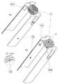
도 2는 본 발명의 바람직한 실시 예에 따른 마우스피스(3)가 전압 소스(4)와, 절연 호일(2)에 제공된 접점 개구(21)을 통해서 접점 탭(13)에 접촉하는 전압 소스(4)의 두 개의 환형 극(41)에 연결되는 방법을 도시한 것이며, 열 저항(1)은 전류를 제공할 수 있고, 저장 카트리지(36)는 전압 소스(4)의 플랜지(33)의 단부면을 통해서 버퍼 저장 공간(321)을 향해서 속이 빈 실린더(31) 내에 축방향으로 배치되며, 저장 카트리지(36)의 씰링 호일(361)은 개구 탭(14)에 의하여 찢어져 개방되고, 활성 물질 및/또는 향 물질을 포함하는 물질은 버퍼 저장 공간(321)으로 유입되고 및 그곳으로부터 기화기 멤브레인(32) 안으로 유입된다.Figure 2 shows a perspective view of a
a) 최초 위치에서 온전한 씰링 호일(361)과 저장 카트리지(36)를 가진 전압 소스(4)가 아직 부착되지 않은 비활성 저장 상태(36)에서의 마우스피스.a) A mouthpiece in an inactive storage state (36) in which the voltage source (4) with the sealing foil (361) and the storage cartridge (36)
b) 최종 위치에서 파괴된 씰링 호일(361)과 저장 카트리지(36)를 가진 활성화된 사용 상태(36)에서의 전압 소스(4)가 부착된 마우스피스.b) a mouthpiece to which a voltage source (4) is attached in an active use state (36) with a sealing foil (361) and a storage cartridge (36)
본 발명의 바람직한 실시 예를 설명한다.A preferred embodiment of the present invention will be described.
본 발명의 바람직한 실시 예에 따르면, 본 발명에 따른 장치는, 예를 들어, WO2011/009920 에 기재된 장치에서 열 저항(1)으로 사용되고, 즉, 본 발명에 따른 장치는 유체가 흐름 채널(31)에서 적어도 하나의 기화기 멤브레인(32)을 통해서 흐르는 장치와 결합되며, 여기서 적어도 하나의 기화기 멤브레인(32)은 기화될 활성 물질 및/또는 향 물질을 포함하는 물질에 젖어있거나 젖고, 활성 물질 및/또는 향 물질을 포함하는 물질에 열 에너지를 공급하는 본 발명에 따른 장치로, 이러한 물질이 기화되어 유체 스트림에 공급되어진다.According to a preferred embodiment of the present invention, the device according to the invention is used, for example, as a
이러한 실시 예에 따라, 본 발명에 따른 장치는 플라스틱 필름, 판지 및 커버 종이로 구성된 속이 빈 실린더(31), 판지의 외측표면 주위를 감싼, 바람직하게 담배 필터의 소위 코르크 종이에 해당하는 상기 커버 종이, 내측 표면에 플라스틱 필름으로 코팅한 판지, 폴리아미드의 절연층(11)으로 코팅되고, 이중 코일(101)의 형태로 알루미늄 호일로부터 펀칭된 투과성 열 저항 호일(1),According to this embodiment, the device according to the invention comprises a
열 저항 호일(1) 상에 접점 탭(13)의 형태로 열 저항 호일(1)로부터 플랜지(33)까지 및 플랜지(33) 안으로 내측 표면을 따라 속이 빈 실린더(31) 내에 세로 방향으로 확장되는, 1/4 원에 해당하는 단면 형상을 가진 두 개의 전기 접점(13),직접 큰 면적으로 접촉하도록 하나의 기화기 멤브레인(32)은 투과성 열 저항 호일(1)의 상류에 배치되고, 다른 하나의 기화기 멤브레인(32)은 다운스트림에 축방향으로 배치되며, 상기 기화기 맴버레인들은 직접 서로 접촉하는 두 개의 투과성 기화기 멤브레인(32), Extending longitudinally into the
기화기 멤브레인(32)이 고막 같이 걸쳐져 가로지르는 흡수성 부직포 링의 형태를 가진 기화기 버퍼 저장 공간(321), 접점 탭(13)으로부터 흐름 채널(31) 안으로 돌출되고, 열 저항 호일(1)로부터 플랜지(33)를 향해 축 방향으로 확장되는 스파이크의 형태를 가진 두 개의 개구 탭(14),A carburetor
두 개의 축방향으로 배치된 접점 개구(21)와 함께 속이 빈 실린더(31)와 접점 탭(31) 내에서 내부 표면을 따라 열 저항 호일(1)로부터 플랜지(33)까지 및 플랜지 안으로 축 방향으로 세로로 확장되는 절연호일(2), 절연호일(2)의 내부 표면과 마우스피스의 측면에 위치한 플랜지(33)의 플랜지 영역(331)을 나타내는 접점 개구(21)를 통하여 노출된 접점 탭 영역,(1) to the flange (33) along the inner surface in the hollow cylinder (31) and the contact tab (31) together with the two axially arranged contact openings (21) A contact tab region exposed through a
속이 빈 실린더(31)의 절연 호일 내에 축방향으로 움직일 수 있는 환형 저장 카트리지(36), 활성 물질 및/또는 향 물질을 포함하고 씰링 호일(361)에 의해 밀봉되는 상기 저장 카트리지, 그리고 열 저항 호일(1)을 향해 개구 탭(14)이 씰링 호일(361)을 뚫을 정도로 움직일 때 상기 저장 카트리지(36)는 파괴되는 상기 씰링 호일(361).An
위에 기술된 본 발명의 바람직한 실시 예는 전압 소스-측면 플랜지(33)의 외부 표면상에 두 개의 환형 극(poles)을 가진 막대-형상(rod-shaped]의 전압 소스와 함께 사용되며, 상기 전압 소스는 플랜지(33)의 종단면에 위치한 공기 배출구를 가지고, 그곳을 통해 유체 스트림은 마우스피스(3)로 흘러들어가며, 전압 소스의 흐름 채널은, 연결된 상태에서, 접점 탭(13)과 마우스피스(3)의 열 저항 호일(1)을 통하여 환형 전극(41)을 경유하여 전압 소스로부터 전류흐름을 제어하는 진공 조정기를 그곳에 제공한다.The preferred embodiment of the invention described above is used with a rod-shaped voltage source having two annular poles on the outer surface of the voltage source-
1; 열 저항(투과성 열 저항 호일) 2; 절연 호일
3; 마우스피스
4; 전압 소스(진공스위치를 가진 배터리 유닛)
11; 절연 층(전기적으로 절연된 플라스틱 층)
12; 안전 휴즈
13; 접점 탭(전기 접점) 14; 개구 탭
31; 중공 실린더(흐름 채널)
32; 기화기 멤브레인(투과성 기화기 멤브레인)
33; 플랜지 34; 위치 홈(groove)
35; 위치 돌출부 36; 저장 카트리지
41; 극(전극(electric pole))
101; 이중 코일 102; 구불구불한 라인
311; 유체 주입구 312; 유체 배출구
313; 유체 채널
321; 버퍼 저장 공간(기화기 버퍼 저장)
331; 플랜지 영역 361; 씰링 호일One; Thermal resistance (permeable heat resistant foil) 2; Insulating foil
3; Mouth piece
4; Voltage source (battery unit with vacuum switch)
11; The insulating layer (electrically insulated plastic layer)
12; Safety Hose
13; Contact tab (electrical contact) 14; Opening tab
31; Hollow cylinder (flow channel)
32; Carburetor membrane (permeable vaporizer membrane)
33; Flange 34; Position groove
35;
41; Pole (electric pole)
101; A
311;
313; Fluid channel
321; Buffer storage (Carburetor buffer storage)
331;
Claims (13)
Translated fromKorean두 개의 단부(ends)와 담배(cigarrette) 또는 작은 시거(cigar)의 단면 크기를 가진 이중 코일(101) 및/또는 구불구불한 라인(102)으로 구성된 금속 호일 또는 얇은 시트의 형태로 열 저항(1)을 가진 가열 장치,
여기서 열 저항(1)의 이중 코일 및/또는 구불구불한 라인의 사이공간은 개방되어, 그곳을 통해서 유체의 흐름이 허용되고,
여기서 금속 호일 또는 얇은 시트로 구성된 적어도 하나의 각 접점 탭(13)은 열 저항(1)의 이중 코일(101) 및/또는 구불구불한 라인(102)의 각 단부에 연결되어, 서로 직접 접촉하지 않으며, 및
열저항(1)과 큰 면적으로 접촉하고, 또한 흐르는 유체가 투과할 수 있고, 기화될 활성 물질 및/또는 향 물질을 포함하고 있는 물질에 젖거나 젖을 수 있는 적어도 하나의 기화기 멤브레인(32)을 포함하고,
여기서 열저항(1)과 적어도 하나의 기화기 멤브레인(32)은 마우스피스(3)을 통과하는 유체의 방향에 수직하게 또는 비스듬히 배열됨을 특징으로 하는 기화기 장치.A vaporizer apparatus for vaporizing a substance comprising an active substance or a fragrance substance, the substance being configured as a mouthpiece (3) having a fluid inlet (311) and a fluid outlet (312)
(In the form of a metal foil or a thin sheet composed of a double coil 101 and / or a twisted line 102 having two ends and a cross-sectional size of a cigarrette or a small cigar) 1), < / RTI >
Wherein the space between the double coils and / or the serpentine lines of the thermal resistor 1 is open, allowing the flow of fluid therethrough,
Wherein at least one respective contact tab 13 made of a metal foil or a thin sheet is connected to each end of the double coil 101 and / or the twisted line 102 of the thermal resistor 1, And
At least one vaporizer membrane 32 which contacts a large area of the thermal resistor 1 and which can also be wetted or wetted by a fluid which is permeable to the flowing fluid and which contains the active and / Including,
Wherein the thermal resistance (1) and the at least one vaporizer membrane (32) are arranged perpendicularly or obliquely to the direction of the fluid passing through the dental mouthpiece (3).
마우스피스(3)는 속이 빈 실린더(31) 형상을 가짐을 특징으로 하는 기화기 장치.The method according to claim 1,
Characterized in that the mouthpiece (3) has the shape of a hollow cylinder (31).
열 저항(1)과 접점 탭(13)은 한 조각의 금속 호일 또는 얇은 시트로 제조된 기화기 장치.The method according to claim 1 or 2,
The heat resistor (1) and the contact tab (13) are made of a piece of metal foil or a thin sheet.
상기 가열 장치는 저장 카트리지(36)를 뚫거나 또는 절단하여 개방하도록 적어도 하나의 뾰족한 및/또는 날카로운 테두리(sharp-edged)의 개구 탭(14)을 더 포함하는 기화기 장치.The method according to claim 1 or 2,
Wherein the heating device further comprises at least one sharp-edged opening tab (14) to pierce or cut open the storage cartridge (36).
열저항(1), 접점 탭(13) 및 개구 탭(14)은 한 조각의 금속 호일 또는 얇은 시트로 제조된 기화기 장치.The method according to claim 1 or 2,
The thermal resistor (1), the contact tab (13) and the open tab (14) are made of a piece of metal foil or a thin sheet.
열 저항(1), 접점 탭(13) 및 개구 탭(14)의 금속 호일 또는 얇은 시트는 순수 알루미늄, 알루미늄-망간 합금 또는 스테인레스 스틸로 구성된 기화기 장치.The method of claim 5,
The metal foil or thin sheet of the thermal resistor (1), the contact tab (13) and the open tab (14) is made of pure aluminum, aluminum-manganese alloy or stainless steel.
열 저항(1)은 절연층(11)으로 코팅되며, 폴리아미드, 미카나이트 또는 실리콘 층으로 코팅된 기화기 장치.The method according to claim 1 or 2,
A thermal resistor (1) is coated with an insulating layer (11) and coated with a polyamide, a micanite or a silicone layer.
열 저항(1)은 이중 코일(101) 및/또는 구불구불한 라인(102)에 압축된 형태의 안전 퓨즈(12)를 포함하는 기화기 장치.The method according to claim 1 or 2,
The thermal resistance (1) comprises a safety fuse (12) in the form of a compressed double coil (101) and / or a serpentine line (102).
기화기 장치는 전극(41)에 의해 제어된 또는 조절된 전압 소스(4)를 분리할 수 있게 연결하기 위한 플랜지(33)를 더 포함하고, 열 저항(1)의 이중 코일(101) 및/또는 구불구불한 라인(102)의 각 각 마주보는 단면에 연결된 접점 탭(13)은 서로 직접적으로 접촉하지는 않고, 제어된 또는 조절된 전압 소스(4)의 전극(41)에 플랜지(33)를 통하여 연결되도록 조절됨을 특징으로 하는 기화기 장치.The method according to claim 1,
The vaporizer device further comprises a flange 33 for releasably connecting a controlled or regulated voltage source 4 by means of an electrode 41 and the dual coil 101 of the thermal resistor 1 and / The contact tabs 13 connected to the respective opposed cross sections of the meandering line 102 do not directly contact each other but are connected to the electrodes 41 of the controlled or regulated voltage source 4 via the flanges 33 And the valve is adjusted to be connected.
마우스피스(3)는 활성 물질 및/또는 향 물질을 포함하고 있는 물질로 채워진 저장 카트리지(36)를 더 포함하고, 여기서 금속 호일 또는 얇은 금속 씨트(sheet)로 구성된 적어도 하나의 뾰족한 및/또는 날카로운-테두리의 개구 탭(14)은, 뾰족한 및/또는 날카로운-테두리의 측면이 먼저 열저항(1)으로부터 마우스피스(3)의 플랜지(33) 방향으로 축방향으로 확장되어, 마우스피스(3)와 전압 소스(4)가 연결되면, 열저항(1)과 플랜지(33) 사이의 저장 카트리지(36)의 씰링 호일(361)이 뚫리거나 상기 개구 탭(14)에 의해 절단되어 개방되도록 수행됨을 특징으로 하는 기화기 장치.The method of claim 9,
The mouthpiece (3) further comprises a storage cartridge (36) filled with a material comprising an active material and / or a fragrance material, wherein at least one pointed and / or sharp The opening tabs 14 of the rim extend axially in the direction of the flange 33 of the mouthpiece 3 from the thermal resistance 1 so that the sides of the sharp and / or sharp- The sealing foil 361 of the storage cartridge 36 between the thermal resistor 1 and the flange 33 is opened or cut open by the opening tab 14 Characterized by a vaporizer device.
전극(41)에 의해 제어된 또는 조절된 전압(40)에 분리할 수 있게 연결된 기화기 장치, 여기서 절연 호일(2)은 마우스피스(3)의 속이 빈 실린더(31)의 내측면에 플랜지 영역을 향해 접점 탭(13)을 커버하고, 및 상기 플랜지 영역(331)의 구역에서 절연호일(2)은 적어도 두 개의 축방향으로 배치된 접점 개구(21)에 제공되며, 상기 접점 개구(21)는 한 평면에 축 방향으로 위치하고, 각각 오직 하나의 접점 탭(13)만을 노출시키도록 구성되고, 여기서 제어된 또는 조절된 전압소스(4)의 전극(14)은 두 개의 축 방향으로 배치된 링이며, 그리고 여기서 마우스피스(3)와 전압(4)이 연결된 상태에서, 전압 소스(4)의 각각의 전극(41)은 접점 개구(21)를 통해 접점 탭(13)에 연결되고, 접점 탭을 통해 열저항(1)의 이중 코일(101) 및/또는 구불구불한 라인(102)의 각 종단에 연결됨을 특징으로 하는 기화기 장치.The method according to claim 9 or 10,
Wherein the insulating foil 2 has a flange area on the inner side of the hollow cylinder 31 of the dental mouthpiece 3, And in the region of said flange region (331) an insulating foil (2) is provided in at least two axially arranged contact openings (21), said contact openings (21) Are arranged axially in one plane and are each arranged to expose only one contact tap (13), wherein the electrodes (14) of the controlled or regulated voltage source (4) are two axially arranged rings Each electrode 41 of the voltage source 4 is connected to the contact tabs 13 through the contact openings 21 and the contact tabs 13 are connected to the contact tabs 13, Is connected to each end of the double coil (101) and / or the winding line (102) of the thermal resistor (1) .
접점 탭(13) 및/또는 플랜지 영역(331)은 적어도 하나의 위치지정 그루브(34) 및/또는 위치지정 돌출부(35)를 포함하고, 상기 위치지정 그루브(34) 및/ 또는 위치지정 돌출부(35)는 제어된 및/또는 조절된 전압 소스(4)에 적어도 하나의 위치지정 그루브(34) 및/또는 위치지정 돌출부(35)로서 구성된 보완적 카운트파트를 가지며, 여기서 마우스피스(3)와 전압 소스(4)가 연결된 상태에서, 전압 소스(4)의 각 전극(41)은 접점 탭(13)에 연결되고, 접점 탭(13)을 통해 열저항(1)의 이중 코일(101) 및/또는 구불구불한 라인(102)의 각 종단에 연결됨을 특징으로 하는 기화기 장치.The method of claim 11,
The contact tabs 13 and / or the flange areas 331 comprise at least one positioning groove 34 and / or a positioning projection 35 and the positioning groove 34 and / 35 has a complementary counting part configured as at least one positioning groove 34 and / or positioning projection 35 in a controlled and / or regulated voltage source 4, wherein the mouthpiece 3 and / With the voltage source 4 connected, each electrode 41 of the voltage source 4 is connected to the contact tap 13 and connected to the dual coil 101 of the thermal resistor 1 through the contact tap 13, And / or connected to each end of the meandering line (102).
Applications Claiming Priority (3)
| Application Number | Priority Date | Filing Date | Title |
|---|---|---|---|
| EP11183197.0AEP2574247B1 (en) | 2011-09-28 | 2011-09-28 | Permeable electric heat resistant foil for evaporating liquids out of disposable mouthpieces with evaporator nozzles |
| EP11183197.0 | 2011-09-28 | ||
| PCT/EP2012/069135WO2013045582A2 (en) | 2011-09-28 | 2012-09-27 | Permeable electrical heat-resistant film for vaporisation of liquids from disposable mouthpieces comprising vaporisation membranes |
Publications (2)
| Publication Number | Publication Date |
|---|---|
| KR20140046022A KR20140046022A (en) | 2014-04-17 |
| KR101634019B1true KR101634019B1 (en) | 2016-06-27 |
Family
ID=47073415
Family Applications (1)
| Application Number | Title | Priority Date | Filing Date |
|---|---|---|---|
| KR1020147003526AActiveKR101634019B1 (en) | 2011-09-28 | 2012-09-27 | Permeable electrical heat-resistant film for vaporisation of liquids from disposable mouthpieces comprising vaporisation membranes |
Country Status (24)
| Country | Link |
|---|---|
| US (1) | US9814265B2 (en) |
| EP (2) | EP2574247B1 (en) |
| JP (1) | JP5849159B2 (en) |
| KR (1) | KR101634019B1 (en) |
| CN (1) | CN104010529B (en) |
| AR (1) | AR088447A1 (en) |
| AU (1) | AU2012314392B2 (en) |
| BR (1) | BR112014007296B1 (en) |
| CA (1) | CA2846286C (en) |
| DK (1) | DK2760302T3 (en) |
| ES (2) | ES2746505T3 (en) |
| HU (2) | HUE045286T2 (en) |
| IL (1) | IL231021A (en) |
| MX (1) | MX342249B (en) |
| MY (1) | MY185436A (en) |
| PH (1) | PH12014500206A1 (en) |
| PL (2) | PL2574247T3 (en) |
| RS (1) | RS54609B1 (en) |
| RU (1) | RU2566914C1 (en) |
| SG (1) | SG2014011845A (en) |
| TW (1) | TWI558327B (en) |
| UA (1) | UA111495C2 (en) |
| WO (1) | WO2013045582A2 (en) |
| ZA (1) | ZA201400870B (en) |
Families Citing this family (155)
| Publication number | Priority date | Publication date | Assignee | Title |
|---|---|---|---|---|
| US20160345631A1 (en) | 2005-07-19 | 2016-12-01 | James Monsees | Portable devices for generating an inhalable vapor |
| GB2504074A (en) | 2012-07-16 | 2014-01-22 | Nicoventures Holdings Ltd | Electronic cigarette |
| US10279934B2 (en) | 2013-03-15 | 2019-05-07 | Juul Labs, Inc. | Fillable vaporizer cartridge and method of filling |
| EP2835063B1 (en)* | 2013-08-06 | 2019-04-10 | Fontem Holdings 1 B.V. | Electronic smoking device and process of manufacturing thereof |
| WO2015026948A1 (en)* | 2013-08-20 | 2015-02-26 | VMR Products, LLC | Vaporizer |
| US10039321B2 (en) | 2013-11-12 | 2018-08-07 | Vmr Products Llc | Vaporizer |
| WO2015073975A1 (en) | 2013-11-15 | 2015-05-21 | VMR Products, LLC | Vaporizer with cover sleeve |
| US10159282B2 (en) | 2013-12-23 | 2018-12-25 | Juul Labs, Inc. | Cartridge for use with a vaporizer device |
| USD842536S1 (en) | 2016-07-28 | 2019-03-05 | Juul Labs, Inc. | Vaporizer cartridge |
| US10058129B2 (en) | 2013-12-23 | 2018-08-28 | Juul Labs, Inc. | Vaporization device systems and methods |
| DE202014011260U1 (en) | 2013-12-23 | 2018-11-13 | Juul Labs Uk Holdco Limited | Systems for an evaporation device |
| USD825102S1 (en) | 2016-07-28 | 2018-08-07 | Juul Labs, Inc. | Vaporizer device with cartridge |
| US10076139B2 (en) | 2013-12-23 | 2018-09-18 | Juul Labs, Inc. | Vaporizer apparatus |
| US20160366947A1 (en) | 2013-12-23 | 2016-12-22 | James Monsees | Vaporizer apparatus |
| TWI761216B (en) | 2014-02-06 | 2022-04-11 | 美商尤爾實驗室有限公司 | A device for generating an inhalable aerosol and a separable cartridge for use therewith |
| US12279646B2 (en) | 2014-02-06 | 2025-04-22 | Juul Labs, Inc. | Cartridge of vaporization device systems having unequal transverse cartridge dimensions |
| US10709173B2 (en) | 2014-02-06 | 2020-07-14 | Juul Labs, Inc. | Vaporizer apparatus |
| KR20230167768A (en) | 2014-02-10 | 2023-12-11 | 필립모리스 프로덕츠 에스.에이. | Cartridge with a heater assembly for an aerosol-generating system |
| MY176431A (en)* | 2014-02-10 | 2020-08-07 | Philip Morris Products Sa | Cartridge for an aerosol-generating system |
| AU2014381789B2 (en) | 2014-02-10 | 2019-03-14 | Philip Morris Products S.A. | Cartridge for an aerosol-generating system |
| KR102515717B1 (en)* | 2014-02-10 | 2023-03-30 | 필립모리스 프로덕츠 에스.에이. | An aerosol-generating system having a fluid-permeable heater assembly |
| US10015990B2 (en) | 2014-02-10 | 2018-07-10 | Phillip Morris Products S.A. | Aerosol-generating system comprising a device and a cartridge, in which the device ensures electrical contact with the cartridge |
| BR112016015685A8 (en) | 2014-02-10 | 2020-06-09 | Philip Morris Products Sa | fluid permeable heater assembly for an aerosol generating system and method for assembling a fluid permeable heater for an aerosol generating system, and aerosol generating system |
| KR20240042543A (en) | 2014-02-10 | 2024-04-02 | 필립모리스 프로덕츠 에스.에이. | An aerosol-generating system having a fluid-permeable heater assembly |
| USD763502S1 (en) | 2014-03-04 | 2016-08-09 | Vmr Products Llc | Cartomizer for a vaporizer |
| USD788697S1 (en) | 2014-03-04 | 2017-06-06 | VMR Products, LLC | Battery portion for a vaporizer |
| USD752278S1 (en) | 2014-03-07 | 2016-03-22 | VMR Products, LLC | Battery portion of a vaporizer |
| USD752280S1 (en) | 2014-03-07 | 2016-03-22 | VMR Products, LLC | Cartomizer for a vaporizer |
| USD749505S1 (en) | 2014-03-07 | 2016-02-16 | VMR Products, LLC | Charger for a vaporizer |
| CN203986095U (en)* | 2014-04-03 | 2014-12-10 | 惠州市吉瑞科技有限公司 | A kind of atomizer and electronic cigarette |
| USD804090S1 (en) | 2014-04-08 | 2017-11-28 | VMR Products, LLC | Vaporizer with indicators |
| AU2015252165B2 (en)* | 2014-04-30 | 2019-01-31 | Philip Morris Products S.A. | A container having a heater for an aerosol-generating device, and aerosol-generating device |
| WO2015165815A1 (en)* | 2014-04-30 | 2015-11-05 | Philip Morris Products S.A. | A container having a heater for an aerosol-generating device, and aerosol-generating device |
| US10398172B2 (en)* | 2014-04-30 | 2019-09-03 | Philip Morris Products S.A. | Container having a heater for an aerosol-generating device, and aerosol-generating device |
| USD750320S1 (en) | 2014-08-05 | 2016-02-23 | VMR Products, LLC | Vaporizer |
| TWI660685B (en) | 2014-05-21 | 2019-06-01 | 瑞士商菲利浦莫里斯製品股份有限公司 | Electrothermal aerosol generating system and cylinder used in the system |
| TWI661782B (en) | 2014-05-21 | 2019-06-11 | 瑞士商菲利浦莫里斯製品股份有限公司 | Electrically heated aerosol-generating system,electrically heated aerosol-generating deviceand method of generating an aerosol |
| GB201411483D0 (en) | 2014-06-27 | 2014-08-13 | Batmark Ltd | Vaporizer Assembly |
| ES2991819T3 (en)* | 2014-06-27 | 2024-12-05 | Fontem Ventures Bv | Electronic smoking device and capsule system |
| GB2527597B (en) | 2014-06-27 | 2016-11-23 | Relco Induction Dev Ltd | Electronic Vapour Inhalers |
| DE102014114133A1 (en)* | 2014-09-29 | 2016-03-31 | Aie Investments S.A. | Electric cigarette |
| US9795168B2 (en) | 2014-10-21 | 2017-10-24 | Xiaochun Zhu | Heating assemblies for E-cigarette vaporizers |
| CN104287098B (en)* | 2014-10-21 | 2017-06-30 | 朱晓春 | A kind of electronic smoke atomizer heat generating component |
| CN104363670A (en)* | 2014-11-16 | 2015-02-18 | 王海嵘 | Electric heating piece |
| MX394125B (en) | 2014-12-05 | 2025-03-24 | Juul Labs Inc | CALIBRATED DOSE CONTROL |
| GB2533135B (en)* | 2014-12-11 | 2020-11-11 | Nicoventures Holdings Ltd | Aerosol provision systems |
| TWI674071B (en)* | 2014-12-15 | 2019-10-11 | 瑞士商菲利浦莫里斯製品股份有限公司 | Aerosol-generating systems and methods for guiding an airflow inside an electrically heated aerosol-generating system |
| KR102745597B1 (en)† | 2014-12-15 | 2024-12-23 | 필립모리스 프로덕츠 에스.에이. | An aerosol-generating system suing the venturi effect to deliver substrate to a heating element |
| AR103016A1 (en)* | 2014-12-15 | 2017-04-12 | Philip Morris Products Sa | AEROSOL GENERATOR SYSTEMS AND METHODS FOR DIRECTING AN AIR FLOW TOWARDS AN ELECTRIC HEATED AEROSOL GENERATOR SYSTEM |
| GB201423312D0 (en) | 2014-12-29 | 2015-02-11 | British American Tobacco Co | Heating device for apparatus for heating smokable material and method of manufacture |
| GB201423316D0 (en) | 2014-12-29 | 2015-02-11 | British American Tobacco Co | Cartridge for use with apparatus for heating smokable material |
| GB201423318D0 (en) | 2014-12-29 | 2015-02-11 | British American Tobacco Co | Cartridge for use with apparatus for heating smokable material |
| GB201423317D0 (en) | 2014-12-29 | 2015-02-11 | British American Tobacco Co | Apparatus for heating smokable material |
| GB201501429D0 (en) | 2015-01-28 | 2015-03-11 | British American Tobacco Co | Apparatus for heating aerosol generating material |
| KR101677547B1 (en)* | 2015-03-20 | 2016-11-18 | 주식회사 케이티앤지 | Smokeless electronic cigarette apparatus |
| US10850051B2 (en) | 2015-03-27 | 2020-12-01 | Philip Morris Products S.A. | Aerosol-generating system comprising a rupturing portion |
| MY197817A (en)* | 2015-04-23 | 2023-07-18 | Altria Client Services Llc | Unitary heating element and heater assemblies, cartridges, and e-vapor devices including a unitary heating element |
| US11882878B2 (en) | 2015-04-23 | 2024-01-30 | Altria Client Services Llc | Heating element and heater assemblies, cartridges, and e-vapor devices including a heating element |
| MY189691A (en)* | 2015-04-23 | 2022-02-26 | Altria Client Services Llc | Unitary heating element and heater assemblies, cartridges, and e-vapor devices including a unitary heating element |
| RU2698550C2 (en)* | 2015-04-30 | 2019-08-28 | Филип Моррис Продактс С.А. | Cartridge for aerosol generating system |
| IL279264B (en) | 2015-05-06 | 2022-09-01 | Altria Client Services Llc | A non-flammable smoking device and its components |
| GB201511358D0 (en) | 2015-06-29 | 2015-08-12 | Nicoventures Holdings Ltd | Electronic aerosol provision systems |
| GB201511361D0 (en) | 2015-06-29 | 2015-08-12 | Nicoventures Holdings Ltd | Electronic vapour provision system |
| GB201511349D0 (en) | 2015-06-29 | 2015-08-12 | Nicoventures Holdings Ltd | Electronic aerosol provision systems |
| GB201511359D0 (en)* | 2015-06-29 | 2015-08-12 | Nicoventures Holdings Ltd | Electronic vapour provision system |
| CN107801375B (en) | 2015-07-09 | 2021-10-26 | 菲利普莫里斯生产公司 | Heater assembly for aerosol-generating system |
| US10206429B2 (en)* | 2015-07-24 | 2019-02-19 | Rai Strategic Holdings, Inc. | Aerosol delivery device with radiant heating |
| US11134544B2 (en) | 2015-07-24 | 2021-09-28 | Rai Strategic Holdings, Inc. | Aerosol delivery device with radiant heating |
| MX2018001418A (en)* | 2015-08-07 | 2018-04-13 | Philip Morris Products Sa | An aerosol-generating system with enhanced airflow management. |
| KR102659808B1 (en) | 2015-08-07 | 2024-04-23 | 필립모리스 프로덕츠 에스.에이. | Aerosol generation system with enhanced airflow management |
| CN108135258B (en) | 2015-08-20 | 2020-07-17 | 富特姆控股第一有限公司 | Electronic smoking device with capillary buffer |
| JP6903646B2 (en)* | 2015-10-22 | 2021-07-14 | フィリップ・モーリス・プロダクツ・ソシエテ・アノニム | Aerosol-generating articles and methods, aerosol generators and systems for manufacturing such aerosol-generating articles. |
| MX2018004535A (en)* | 2015-10-22 | 2018-06-27 | Philip Morris Products Sa | Aerosol-generating article, aerosol-generating system and method for manufacturing an aerosol-generating article. |
| CN120586220A (en)* | 2016-01-11 | 2025-09-05 | Syqe医药有限公司 | Personal evaporation device |
| JP2019500975A (en)* | 2016-01-11 | 2019-01-17 | アリゾナ ボード オブ リージェンツ オン ビハーフ オブ アリゾナ ステート ユニバーシティ | Heated steam suction device for pharmaceutical waxes, solids, biopolymers, or highly viscous oils and cannabinoids |
| EP3413960B1 (en) | 2016-02-11 | 2021-03-31 | Juul Labs, Inc. | Fillable vaporizer cartridge and method of filling |
| CO2018009342A2 (en) | 2016-02-11 | 2018-09-20 | Juul Labs Inc | Secure fixing cartridges for vaporizing devices |
| UA126061C2 (en) | 2016-02-25 | 2022-08-10 | Джуул Лебз, Інк. | SYSTEMS AND METHODS OF CONTROLLING THE EVAPORATION DEVICE |
| RU2736380C2 (en) | 2016-03-09 | 2020-11-16 | Филип Моррис Продактс С.А. | Aerosol-generating article having a plurality of fuses |
| US10405582B2 (en) | 2016-03-10 | 2019-09-10 | Pax Labs, Inc. | Vaporization device with lip sensing |
| FR3049152B1 (en)* | 2016-03-21 | 2018-04-13 | Valeo Systemes D'essuyage | HEATING ELEMENT FOR A WIPER BLADE OF A VEHICLE |
| US10251424B2 (en) | 2016-03-22 | 2019-04-09 | Altria Client Services Llc | Electronic vaping device |
| GB201605102D0 (en) | 2016-03-24 | 2016-05-11 | Nicoventures Holdings Ltd | Mechanical connector for electronic vapour provision system |
| US10244795B2 (en)* | 2016-03-31 | 2019-04-02 | Altria Client Services Llc | Vaporizing assembly comprising sheet heating element and liquid delivery device for an aerosol generating system |
| US10631572B2 (en) | 2016-03-31 | 2020-04-28 | Altria Client Services Llc | Aerosol-generating system with separate capsule and vaporizing unit |
| MX2018011471A (en)* | 2016-03-31 | 2019-01-10 | Philip Morris Products Sa | Vaporizing assembly comprising sheet heating element and liquid delivery device for an aerosol generating system. |
| ITUA20162410A1 (en)* | 2016-04-08 | 2017-10-08 | Gd Spa | Method and inspection unit of a heating element for electronic cigarette. |
| EP3756712B1 (en) | 2016-05-31 | 2023-05-24 | Philip Morris Products S.A. | Aerosol generating device with integral heater assembly |
| US10952471B2 (en) | 2016-05-31 | 2021-03-23 | Altria Client Services Llc | Aerosol-generating device with integral heater assembly |
| USD849996S1 (en) | 2016-06-16 | 2019-05-28 | Pax Labs, Inc. | Vaporizer cartridge |
| US10881140B2 (en) | 2016-06-20 | 2021-01-05 | Altria Client Services Llc | Vaporiser assembly for an aerosol-generating system |
| CN109152428B (en)* | 2016-06-20 | 2022-05-03 | 菲利普莫里斯生产公司 | Evaporator Components for Aerosol Generation Systems |
| USD836541S1 (en) | 2016-06-23 | 2018-12-25 | Pax Labs, Inc. | Charging device |
| USD851830S1 (en) | 2016-06-23 | 2019-06-18 | Pax Labs, Inc. | Combined vaporizer tamp and pick tool |
| USD848057S1 (en) | 2016-06-23 | 2019-05-07 | Pax Labs, Inc. | Lid for a vaporizer |
| UA124462C2 (en) | 2016-07-25 | 2021-09-22 | Філіп Морріс Продактс С.А. | CARTRIDGE FOR SYSTEM GENERATING AN AEROSOL WITH HEATER PROTECTION |
| US10327477B2 (en) | 2016-07-25 | 2019-06-25 | Altria Client Services Llc | Cartridge for an aerosol-generating system with heater protection |
| US10575560B2 (en) | 2016-07-29 | 2020-03-03 | Altria Client Services Llc | Method of making a heater of an electronic vaping device |
| CN106255244A (en)* | 2016-08-17 | 2016-12-21 | 电子科技大学 | A kind of thin film heater improving temperature field uniformity |
| CN106255243A (en)* | 2016-08-17 | 2016-12-21 | 电子科技大学 | A kind of snakelike thin film heater regulating temperature homogeneity and method for regulating temperature thereof |
| US20180070634A1 (en)* | 2016-09-09 | 2018-03-15 | Rai Strategic Holdings, Inc. | Analog control component for an aerosol delivery device |
| US10842193B2 (en) | 2016-10-04 | 2020-11-24 | Altria Client Services Llc | Non-combustible smoking device and elements thereof |
| US10440994B2 (en) | 2016-11-03 | 2019-10-15 | Altria Client Services Llc | Vaporizer assembly for e-vaping device |
| RU2765142C2 (en)* | 2016-12-22 | 2022-01-26 | Филип Моррис Продактс С.А. | Aerosol-generating system with electrode pairs |
| US10433585B2 (en) | 2016-12-28 | 2019-10-08 | Altria Client Services Llc | Non-combustible smoking systems, devices and elements thereof |
| GB201700812D0 (en) | 2017-01-17 | 2017-03-01 | British American Tobacco Investments Ltd | Apparatus for heating smokable material |
| CA3054273C (en) | 2017-03-06 | 2022-01-11 | Japan Tobacco Inc. | Battery unit, flavor inhaler, method for controlling battery unit, and program |
| CA3054492C (en) | 2017-03-06 | 2022-11-29 | Japan Tobacco Inc. | Battery unit, flavor inhaler, method of controlling battery unit, and program |
| EA201992106A1 (en) | 2017-03-06 | 2020-02-03 | Джапан Тобакко Инк. | BATTERY UNIT, INHALATOR FOR TASTE AROMATIC MATERIAL, METHOD FOR MANAGING THE BATTERY UNIT AND PROGRAM |
| DE102017111119B4 (en)* | 2017-05-22 | 2020-12-31 | Hauni Maschinenbau Gmbh | Vaporizer unit for an inhaler |
| US10994086B2 (en) | 2017-06-29 | 2021-05-04 | Altria Client Services Llc | Electronic vaping device with tubular heating element |
| EP3675661B1 (en) | 2017-08-28 | 2023-06-07 | Juul Labs, Inc. | Wick for vaporizer device |
| USD887632S1 (en) | 2017-09-14 | 2020-06-16 | Pax Labs, Inc. | Vaporizer cartridge |
| US12232224B2 (en) | 2017-10-11 | 2025-02-18 | Altria Client Services Llc | Folded heater for electronic vaping device |
| US12396482B2 (en) | 2017-10-11 | 2025-08-26 | Altria Client Services Llc | Electronic vaping device including transfer pad with oriented fibers |
| US10772356B2 (en) | 2017-10-11 | 2020-09-15 | Altria Client Services Llc | Electronic vaping device including transfer pad with oriented fibers |
| USD870375S1 (en) | 2017-10-11 | 2019-12-17 | Altria Client Services Llc | Battery for an electronic vaping device |
| RU2737812C1 (en)* | 2017-12-06 | 2020-12-03 | Джапан Тобакко Инк. | Cartridge of aerosol inhaler, aerosol inhaler and metal heater of aerosol inhaler |
| US10687557B2 (en) | 2017-12-29 | 2020-06-23 | Altria Client Services Llc | Electronic vaping device with outlet-end illumination |
| CN108185536B (en) | 2018-02-13 | 2020-01-21 | 深圳麦克韦尔科技有限公司 | Electronic cigarette and atomizer thereof |
| EP3753425B1 (en) | 2018-02-13 | 2024-12-18 | Shenzhen Smoore Technology Limited | Heating assembly for an electronic cigarette |
| WO2019157651A1 (en)* | 2018-02-13 | 2019-08-22 | 深圳麦克韦尔股份有限公司 | Electronic cigarette and heating assembly and heating member thereof |
| US12121061B2 (en) | 2018-02-13 | 2024-10-22 | Shenzhen Smoore Technology Limited | Electronic cigarette and heating assembly thereof |
| WO2019157647A1 (en) | 2018-02-13 | 2019-08-22 | 深圳麦克韦尔股份有限公司 | Electronic cigarette and heating assembly and heating member thereof |
| WO2019224078A1 (en)* | 2018-05-21 | 2019-11-28 | Jt International Sa | An inhalation system, an inhalation device and a vapour generating article |
| CA3099825A1 (en)* | 2018-05-21 | 2019-11-28 | Jt International Sa | An inhalation system, an inhalation device and a vapour generating article |
| CN112074200B (en) | 2018-05-25 | 2023-11-24 | 菲利普莫里斯生产公司 | Molded barrel assembly |
| EP3813914B1 (en) | 2018-06-26 | 2023-10-25 | Juul Labs, Inc. | Vaporizer wicking elements |
| US12214562B2 (en) | 2018-07-23 | 2025-02-04 | Juul Labs, Inc. | Cartridge for vaporizer device |
| CN110754696A (en) | 2018-07-23 | 2020-02-07 | 尤尔实验室有限公司 | Airflow management for evaporator units |
| US12431568B2 (en) | 2018-07-30 | 2025-09-30 | Altria Client Services Llc | Electronic vaping device |
| DE102018120392B4 (en)* | 2018-08-21 | 2021-08-05 | Sergej Klein | Vaporizer device for aromatic substances |
| WO2020074515A1 (en)* | 2018-10-08 | 2020-04-16 | Philip Morris Products S.A. | Heater shell of heater assembly for an aerosol-generating device |
| SG11202103757VA (en) | 2018-10-15 | 2021-05-28 | Juul Labs Inc | Heating element |
| US12256784B2 (en) | 2018-10-17 | 2025-03-25 | Juul Labs, Inc. | Cartridge for a vaporizer device |
| JP7660503B2 (en) | 2018-11-05 | 2025-04-11 | ジュール・ラブズ・インコーポレイテッド | Cartridges for vaporizer devices |
| WO2020105132A1 (en)* | 2018-11-21 | 2020-05-28 | 日本たばこ産業株式会社 | Atomization unit production method and atomization unit |
| GB201901067D0 (en)* | 2019-01-25 | 2019-03-13 | Nicoventures Trading Ltd | Assembly for insertion into an aerosol provision device |
| CA3103590C (en)* | 2019-10-15 | 2021-12-07 | Canopy Growth Corporation | Vaporizer charging structure |
| IL293919B2 (en) | 2019-12-19 | 2025-08-01 | Philip Morris Products Sa | Cartridge for an aerosol generation system, an aerosol generation system including a cartridge, and a method for manufacturing a heating assembly and cartridge for an aerosol generation system |
| WO2021141251A1 (en)* | 2020-01-06 | 2021-07-15 | Kt&G Corporation | Aerosol generating device |
| WO2021141246A1 (en) | 2020-01-06 | 2021-07-15 | Kt&G Corporation | Aerosol generating device |
| WO2021141259A1 (en) | 2020-01-06 | 2021-07-15 | Kt&G Corporation | Aerosol generating system |
| KR102446416B1 (en)* | 2020-01-06 | 2022-09-23 | 주식회사 케이티앤지 | aerosol generating device |
| JP6927612B1 (en)* | 2020-04-10 | 2021-09-01 | 坂口電熱株式会社 | Water-based heating paint and sheet heating element |
| CA3169909A1 (en)* | 2020-05-28 | 2021-12-02 | Claude Zominy | Heating elements for an aerosol generating device |
| KR102455535B1 (en)* | 2020-06-16 | 2022-10-17 | 주식회사 케이티앤지 | Aerosol generating apparatus and method for operating the same |
| CN111838758B (en)* | 2020-07-23 | 2023-08-11 | 内蒙古昆明卷烟有限责任公司 | Cigarette holder and smoking set assembly using same |
| US12426630B2 (en) | 2020-12-10 | 2025-09-30 | Blackship Technologies Development Llc | Disposable vaporizer cartridge |
| WO2022207536A1 (en)* | 2021-03-30 | 2022-10-06 | Jt International Sa | Heating assembly for an aerosol generating device |
| US20240358074A1 (en)* | 2021-09-08 | 2024-10-31 | Philip Morris Products S.A. | Aerosol generating consumable with fuse element |
| EP4451973A1 (en)* | 2021-12-22 | 2024-10-30 | Nicoventures Trading Limited | Delivery system |
| WO2023226714A1 (en)* | 2022-05-21 | 2023-11-30 | 常州市派腾电子技术服务有限公司 | Atomizer and aerosol generating device |
| KR20240039293A (en)* | 2022-09-19 | 2024-03-26 | 주식회사 케이티앤지 | Inhaler |
| DE102022126973B4 (en) | 2022-10-14 | 2024-05-16 | Michail Turko | Device for multiple ignition and extinguishing of cigarettes |
Citations (2)
| Publication number | Priority date | Publication date | Assignee | Title |
|---|---|---|---|---|
| JP2012533313A (en) | 2009-07-22 | 2012-12-27 | ヴェデグレー ゲーエムベーハー | Smokeless tobacco substitute product |
| JP2013516159A (en) | 2009-12-30 | 2013-05-13 | フィリップ・モーリス・プロダクツ・ソシエテ・アノニム | An improved heater for an electrically heated aerosol generation system. |
Family Cites Families (17)
| Publication number | Priority date | Publication date | Assignee | Title |
|---|---|---|---|---|
| DE1565641C3 (en)* | 1966-11-05 | 1975-07-10 | Kabelwerk Wagner Kg, 5600 Wuppertal | Method of manufacturing a heating mat |
| DE2853398C3 (en) | 1978-12-11 | 1981-09-17 | Unilever N.V., Rotterdam | Method and device for simultaneous biaxial stretching of a plastic film web |
| US5144962A (en) | 1989-12-01 | 1992-09-08 | Philip Morris Incorporated | Flavor-delivery article |
| US5388594A (en)* | 1991-03-11 | 1995-02-14 | Philip Morris Incorporated | Electrical smoking system for delivering flavors and method for making same |
| CR4906A (en)* | 1993-09-10 | 1994-09-09 | Philip Morris Prod | ELECTRIC SMOKING SYSTEM TO DISTRIBUTE FLAVORS AND METHOD FOR ITS MANUFACTURE |
| US5649554A (en)* | 1995-10-16 | 1997-07-22 | Philip Morris Incorporated | Electrical lighter with a rotatable tobacco supply |
| CN2244307Y (en)* | 1995-11-20 | 1997-01-08 | 吴际平 | Appliance for giving up smoking |
| US7077130B2 (en)* | 2000-12-22 | 2006-07-18 | Chrysalis Technologies Incorporated | Disposable inhaler system |
| CA2502171C (en)* | 2002-10-31 | 2013-01-15 | Philip Morris Products S.A. | Electrically heated cigarette including controlled-release flavoring |
| JP2005034021A (en) | 2003-07-17 | 2005-02-10 | Seiko Epson Corp | Electronic Cigarette |
| CN101262786B (en) | 2005-05-25 | 2015-04-08 | 美国无烟烟草有限责任公司 | tobacco composition |
| US20070102013A1 (en) | 2005-09-30 | 2007-05-10 | Philip Morris Usa Inc. | Electrical smoking system |
| CN201067079Y (en) | 2006-05-16 | 2008-06-04 | 韩力 | Simulated aerosol inhaler |
| EP1972215A1 (en) | 2007-03-20 | 2008-09-24 | Wedegree GmbH | Smoke-free cigarette substitute |
| ES2706326T3 (en) | 2008-02-29 | 2019-03-28 | Yunqiang Xiu | Electronic simulated cigarette and smoking equipment comprising said electronic simulated cigarette |
| RU2360583C1 (en)* | 2008-04-28 | 2009-07-10 | Владимир Николаевич Урцев | Tobacco pipe for smokeless smoking |
| WO2012006722A1 (en)* | 2010-07-13 | 2012-01-19 | Tyler Johnson | Portable rechargeable battery powered flameless cigar lighter |
- 2011
- 2011-09-28HUHUE11183197Apatent/HUE045286T2/enunknown
- 2011-09-28PLPL11183197Tpatent/PL2574247T3/enunknown
- 2011-09-28EPEP11183197.0Apatent/EP2574247B1/enactiveActive
- 2011-09-28ESES11183197Tpatent/ES2746505T3/enactiveActive
- 2012
- 2012-09-27USUS14/344,026patent/US9814265B2/enactiveActive
- 2012-09-27CACA2846286Apatent/CA2846286C/enactiveActive
- 2012-09-27RSRS20160135Apatent/RS54609B1/enunknown
- 2012-09-27UAUAA201402193Apatent/UA111495C2/enunknown
- 2012-09-27TWTW101135443Apatent/TWI558327B/enactive
- 2012-09-27ESES12777874.4Tpatent/ES2567641T3/enactiveActive
- 2012-09-27CNCN201280045111.3Apatent/CN104010529B/enactiveActive
- 2012-09-27PLPL12777874.4Tpatent/PL2760302T3/enunknown
- 2012-09-27WOPCT/EP2012/069135patent/WO2013045582A2/enactiveApplication Filing
- 2012-09-27EPEP12777874.4Apatent/EP2760302B1/enactiveActive
- 2012-09-27HUHUE12777874Apatent/HUE026825T2/enunknown
- 2012-09-27MYMYPI2014000302Apatent/MY185436A/enunknown
- 2012-09-27JPJP2014532392Apatent/JP5849159B2/enactiveActive
- 2012-09-27PHPH1/2014/500206Apatent/PH12014500206A1/enunknown
- 2012-09-27SGSG2014011845Apatent/SG2014011845A/enunknown
- 2012-09-27KRKR1020147003526Apatent/KR101634019B1/enactiveActive
- 2012-09-27AUAU2012314392Apatent/AU2012314392B2/enactiveActive
- 2012-09-27DKDK12777874.4Tpatent/DK2760302T3/enactive
- 2012-09-27RURU2014116984/12Apatent/RU2566914C1/enactive
- 2012-09-27MXMX2014003877Apatent/MX342249B/enactiveIP Right Grant
- 2012-09-27BRBR112014007296-5Apatent/BR112014007296B1/enactiveIP Right Grant
- 2012-09-28ARARP120103640Apatent/AR088447A1/enactiveIP Right Grant
- 2014
- 2014-02-05ZAZA2014/00870Apatent/ZA201400870B/enunknown
- 2014-02-18ILIL231021Apatent/IL231021A/enactiveIP Right Grant
Patent Citations (2)
| Publication number | Priority date | Publication date | Assignee | Title |
|---|---|---|---|---|
| JP2012533313A (en) | 2009-07-22 | 2012-12-27 | ヴェデグレー ゲーエムベーハー | Smokeless tobacco substitute product |
| JP2013516159A (en) | 2009-12-30 | 2013-05-13 | フィリップ・モーリス・プロダクツ・ソシエテ・アノニム | An improved heater for an electrically heated aerosol generation system. |
Also Published As
Similar Documents
| Publication | Publication Date | Title |
|---|---|---|
| KR101634019B1 (en) | Permeable electrical heat-resistant film for vaporisation of liquids from disposable mouthpieces comprising vaporisation membranes | |
| JP6895021B2 (en) | Aerosol generator and system | |
| JP7141521B2 (en) | Aerosol-generating articles, aerosol-generating devices and aerosol-generating systems | |
| RU2732766C2 (en) | Aerosol-generating system comprising a heated article which generates an aerosol | |
| KR102658121B1 (en) | Aerosol-generating device with detachable venturi element | |
| RU2701846C2 (en) | Aerosol-forming system using venturi effect for delivering substrate to heating element | |
| JP2018046847A (en) | Electronic smoking article and improved heater element | |
| US9351522B2 (en) | Cartomizer e-cigarette | |
| CN107635419A (en) | Non-combustion smoking devices and components thereof | |
| KR20200061099A (en) | A cigarette including an outer wrapper | |
| RU111765U1 (en) | PERSONAL INHALATOR | |
| JP6749503B2 (en) | Vaporizer and method for vaporization for an aerosol generating system | |
| NZ621422B2 (en) | Vaporizer device having a heating device with a thermal resistor | |
| RU2791078C1 (en) | Aerosol generating device with separable venturi element and aerosol generating system | |
| HK1198108B (en) | Vaporator with a permeable electrical heat-resistant film and a vaporisation membrane | |
| RU2805451C2 (en) | Nebulizer for electrically heated aerosol generating system, electrically heated aerosol generating system (embodiments) and cartridge for aerosol generating system |
Legal Events
| Date | Code | Title | Description |
|---|---|---|---|
| A201 | Request for examination | ||
| PA0105 | International application | Patent event date:20140211 Patent event code:PA01051R01D Comment text:International Patent Application | |
| PA0201 | Request for examination | ||
| PG1501 | Laying open of application | ||
| E902 | Notification of reason for refusal | ||
| PE0902 | Notice of grounds for rejection | Comment text:Notification of reason for refusal Patent event date:20151021 Patent event code:PE09021S01D | |
| E701 | Decision to grant or registration of patent right | ||
| PE0701 | Decision of registration | Patent event code:PE07011S01D Comment text:Decision to Grant Registration Patent event date:20160414 | |
| GRNT | Written decision to grant | ||
| PR0701 | Registration of establishment | Comment text:Registration of Establishment Patent event date:20160621 Patent event code:PR07011E01D | |
| PR1002 | Payment of registration fee | Payment date:20160621 End annual number:3 Start annual number:1 | |
| PG1601 | Publication of registration | ||
| PR1001 | Payment of annual fee | Payment date:20200611 Start annual number:5 End annual number:5 | |
| PR1001 | Payment of annual fee | Payment date:20240613 Start annual number:9 End annual number:9 |