KR101632908B1 - Cage assembly for spine interbody fusion - Google Patents
Cage assembly for spine interbody fusionDownload PDFInfo
- Publication number
- KR101632908B1 KR101632908B1KR1020140028919AKR20140028919AKR101632908B1KR 101632908 B1KR101632908 B1KR 101632908B1KR 1020140028919 AKR1020140028919 AKR 1020140028919AKR 20140028919 AKR20140028919 AKR 20140028919AKR 101632908 B1KR101632908 B1KR 101632908B1
- Authority
- KR
- South Korea
- Prior art keywords
- main body
- center
- space
- cage assembly
- width
- Prior art date
- Legal status (The legal status is an assumption and is not a legal conclusion. Google has not performed a legal analysis and makes no representation as to the accuracy of the status listed.)
- Active
Links
Images


Classifications
- A—HUMAN NECESSITIES
- A61—MEDICAL OR VETERINARY SCIENCE; HYGIENE
- A61B—DIAGNOSIS; SURGERY; IDENTIFICATION
- A61B17/00—Surgical instruments, devices or methods
- A61B17/56—Surgical instruments or methods for treatment of bones or joints; Devices specially adapted therefor
- A61B17/58—Surgical instruments or methods for treatment of bones or joints; Devices specially adapted therefor for osteosynthesis, e.g. bone plates, screws or setting implements
- A61B17/68—Internal fixation devices, including fasteners and spinal fixators, even if a part thereof projects from the skin
- A61B17/70—Spinal positioners or stabilisers, e.g. stabilisers comprising fluid filler in an implant
- A—HUMAN NECESSITIES
- A61—MEDICAL OR VETERINARY SCIENCE; HYGIENE
- A61F—FILTERS IMPLANTABLE INTO BLOOD VESSELS; PROSTHESES; DEVICES PROVIDING PATENCY TO, OR PREVENTING COLLAPSING OF, TUBULAR STRUCTURES OF THE BODY, e.g. STENTS; ORTHOPAEDIC, NURSING OR CONTRACEPTIVE DEVICES; FOMENTATION; TREATMENT OR PROTECTION OF EYES OR EARS; BANDAGES, DRESSINGS OR ABSORBENT PADS; FIRST-AID KITS
- A61F2/00—Filters implantable into blood vessels; Prostheses, i.e. artificial substitutes or replacements for parts of the body; Appliances for connecting them with the body; Devices providing patency to, or preventing collapsing of, tubular structures of the body, e.g. stents
- A61F2/02—Prostheses implantable into the body
- A61F2/30—Joints
- A61F2/44—Joints for the spine, e.g. vertebrae, spinal discs
- A61F2/4455—Joints for the spine, e.g. vertebrae, spinal discs for the fusion of spinal bodies, e.g. intervertebral fusion of adjacent spinal bodies, e.g. fusion cages
- A61F2/447—Joints for the spine, e.g. vertebrae, spinal discs for the fusion of spinal bodies, e.g. intervertebral fusion of adjacent spinal bodies, e.g. fusion cages substantially parallelepipedal, e.g. having a rectangular or trapezoidal cross-section
- A—HUMAN NECESSITIES
- A61—MEDICAL OR VETERINARY SCIENCE; HYGIENE
- A61F—FILTERS IMPLANTABLE INTO BLOOD VESSELS; PROSTHESES; DEVICES PROVIDING PATENCY TO, OR PREVENTING COLLAPSING OF, TUBULAR STRUCTURES OF THE BODY, e.g. STENTS; ORTHOPAEDIC, NURSING OR CONTRACEPTIVE DEVICES; FOMENTATION; TREATMENT OR PROTECTION OF EYES OR EARS; BANDAGES, DRESSINGS OR ABSORBENT PADS; FIRST-AID KITS
- A61F2/00—Filters implantable into blood vessels; Prostheses, i.e. artificial substitutes or replacements for parts of the body; Appliances for connecting them with the body; Devices providing patency to, or preventing collapsing of, tubular structures of the body, e.g. stents
- A61F2/02—Prostheses implantable into the body
- A61F2/30—Joints
- A61F2/44—Joints for the spine, e.g. vertebrae, spinal discs
- A61F2/442—Intervertebral or spinal discs, e.g. resilient
- A—HUMAN NECESSITIES
- A61—MEDICAL OR VETERINARY SCIENCE; HYGIENE
- A61F—FILTERS IMPLANTABLE INTO BLOOD VESSELS; PROSTHESES; DEVICES PROVIDING PATENCY TO, OR PREVENTING COLLAPSING OF, TUBULAR STRUCTURES OF THE BODY, e.g. STENTS; ORTHOPAEDIC, NURSING OR CONTRACEPTIVE DEVICES; FOMENTATION; TREATMENT OR PROTECTION OF EYES OR EARS; BANDAGES, DRESSINGS OR ABSORBENT PADS; FIRST-AID KITS
- A61F2/00—Filters implantable into blood vessels; Prostheses, i.e. artificial substitutes or replacements for parts of the body; Appliances for connecting them with the body; Devices providing patency to, or preventing collapsing of, tubular structures of the body, e.g. stents
- A61F2/02—Prostheses implantable into the body
- A61F2/30—Joints
- A61F2/44—Joints for the spine, e.g. vertebrae, spinal discs
- A61F2/4455—Joints for the spine, e.g. vertebrae, spinal discs for the fusion of spinal bodies, e.g. intervertebral fusion of adjacent spinal bodies, e.g. fusion cages
- A61F2/4465—Joints for the spine, e.g. vertebrae, spinal discs for the fusion of spinal bodies, e.g. intervertebral fusion of adjacent spinal bodies, e.g. fusion cages having a circular or kidney shaped cross-section substantially perpendicular to the axis of the spine
- A—HUMAN NECESSITIES
- A61—MEDICAL OR VETERINARY SCIENCE; HYGIENE
- A61F—FILTERS IMPLANTABLE INTO BLOOD VESSELS; PROSTHESES; DEVICES PROVIDING PATENCY TO, OR PREVENTING COLLAPSING OF, TUBULAR STRUCTURES OF THE BODY, e.g. STENTS; ORTHOPAEDIC, NURSING OR CONTRACEPTIVE DEVICES; FOMENTATION; TREATMENT OR PROTECTION OF EYES OR EARS; BANDAGES, DRESSINGS OR ABSORBENT PADS; FIRST-AID KITS
- A61F2/00—Filters implantable into blood vessels; Prostheses, i.e. artificial substitutes or replacements for parts of the body; Appliances for connecting them with the body; Devices providing patency to, or preventing collapsing of, tubular structures of the body, e.g. stents
- A61F2/02—Prostheses implantable into the body
- A61F2/30—Joints
- A61F2/46—Special tools for implanting artificial joints
- A—HUMAN NECESSITIES
- A61—MEDICAL OR VETERINARY SCIENCE; HYGIENE
- A61F—FILTERS IMPLANTABLE INTO BLOOD VESSELS; PROSTHESES; DEVICES PROVIDING PATENCY TO, OR PREVENTING COLLAPSING OF, TUBULAR STRUCTURES OF THE BODY, e.g. STENTS; ORTHOPAEDIC, NURSING OR CONTRACEPTIVE DEVICES; FOMENTATION; TREATMENT OR PROTECTION OF EYES OR EARS; BANDAGES, DRESSINGS OR ABSORBENT PADS; FIRST-AID KITS
- A61F2/00—Filters implantable into blood vessels; Prostheses, i.e. artificial substitutes or replacements for parts of the body; Appliances for connecting them with the body; Devices providing patency to, or preventing collapsing of, tubular structures of the body, e.g. stents
- A61F2/02—Prostheses implantable into the body
- A61F2/30—Joints
- A61F2002/30001—Additional features of subject-matter classified in A61F2/28, A61F2/30 and subgroups thereof
- A61F2002/30316—The prosthesis having different structural features at different locations within the same prosthesis; Connections between prosthetic parts; Special structural features of bone or joint prostheses not otherwise provided for
- A61F2002/30535—Special structural features of bone or joint prostheses not otherwise provided for
- A61F2002/30593—Special structural features of bone or joint prostheses not otherwise provided for hollow
- A—HUMAN NECESSITIES
- A61—MEDICAL OR VETERINARY SCIENCE; HYGIENE
- A61F—FILTERS IMPLANTABLE INTO BLOOD VESSELS; PROSTHESES; DEVICES PROVIDING PATENCY TO, OR PREVENTING COLLAPSING OF, TUBULAR STRUCTURES OF THE BODY, e.g. STENTS; ORTHOPAEDIC, NURSING OR CONTRACEPTIVE DEVICES; FOMENTATION; TREATMENT OR PROTECTION OF EYES OR EARS; BANDAGES, DRESSINGS OR ABSORBENT PADS; FIRST-AID KITS
- A61F2/00—Filters implantable into blood vessels; Prostheses, i.e. artificial substitutes or replacements for parts of the body; Appliances for connecting them with the body; Devices providing patency to, or preventing collapsing of, tubular structures of the body, e.g. stents
- A61F2/02—Prostheses implantable into the body
- A61F2/30—Joints
- A61F2/30721—Accessories
- A61F2/30734—Modular inserts, sleeves or augments, e.g. placed on proximal part of stem for fixation purposes or wedges for bridging a bone defect
- A61F2002/30736—Augments or augmentation pieces, e.g. wedges or blocks for bridging a bone defect
- A—HUMAN NECESSITIES
- A61—MEDICAL OR VETERINARY SCIENCE; HYGIENE
- A61F—FILTERS IMPLANTABLE INTO BLOOD VESSELS; PROSTHESES; DEVICES PROVIDING PATENCY TO, OR PREVENTING COLLAPSING OF, TUBULAR STRUCTURES OF THE BODY, e.g. STENTS; ORTHOPAEDIC, NURSING OR CONTRACEPTIVE DEVICES; FOMENTATION; TREATMENT OR PROTECTION OF EYES OR EARS; BANDAGES, DRESSINGS OR ABSORBENT PADS; FIRST-AID KITS
- A61F2/00—Filters implantable into blood vessels; Prostheses, i.e. artificial substitutes or replacements for parts of the body; Appliances for connecting them with the body; Devices providing patency to, or preventing collapsing of, tubular structures of the body, e.g. stents
- A61F2/02—Prostheses implantable into the body
- A61F2/30—Joints
- A61F2/30767—Special external or bone-contacting surface, e.g. coating for improving bone ingrowth
- A61F2/30771—Special external or bone-contacting surface, e.g. coating for improving bone ingrowth applied in original prostheses, e.g. holes or grooves
- A61F2002/30772—Apertures or holes, e.g. of circular cross section
- A61F2002/30777—Oblong apertures
- A—HUMAN NECESSITIES
- A61—MEDICAL OR VETERINARY SCIENCE; HYGIENE
- A61F—FILTERS IMPLANTABLE INTO BLOOD VESSELS; PROSTHESES; DEVICES PROVIDING PATENCY TO, OR PREVENTING COLLAPSING OF, TUBULAR STRUCTURES OF THE BODY, e.g. STENTS; ORTHOPAEDIC, NURSING OR CONTRACEPTIVE DEVICES; FOMENTATION; TREATMENT OR PROTECTION OF EYES OR EARS; BANDAGES, DRESSINGS OR ABSORBENT PADS; FIRST-AID KITS
- A61F2/00—Filters implantable into blood vessels; Prostheses, i.e. artificial substitutes or replacements for parts of the body; Appliances for connecting them with the body; Devices providing patency to, or preventing collapsing of, tubular structures of the body, e.g. stents
- A61F2/02—Prostheses implantable into the body
- A61F2/30—Joints
- A61F2/30767—Special external or bone-contacting surface, e.g. coating for improving bone ingrowth
- A61F2/30771—Special external or bone-contacting surface, e.g. coating for improving bone ingrowth applied in original prostheses, e.g. holes or grooves
- A61F2002/30772—Apertures or holes, e.g. of circular cross section
- A61F2002/30784—Plurality of holes
- A—HUMAN NECESSITIES
- A61—MEDICAL OR VETERINARY SCIENCE; HYGIENE
- A61F—FILTERS IMPLANTABLE INTO BLOOD VESSELS; PROSTHESES; DEVICES PROVIDING PATENCY TO, OR PREVENTING COLLAPSING OF, TUBULAR STRUCTURES OF THE BODY, e.g. STENTS; ORTHOPAEDIC, NURSING OR CONTRACEPTIVE DEVICES; FOMENTATION; TREATMENT OR PROTECTION OF EYES OR EARS; BANDAGES, DRESSINGS OR ABSORBENT PADS; FIRST-AID KITS
- A61F2/00—Filters implantable into blood vessels; Prostheses, i.e. artificial substitutes or replacements for parts of the body; Appliances for connecting them with the body; Devices providing patency to, or preventing collapsing of, tubular structures of the body, e.g. stents
- A61F2/02—Prostheses implantable into the body
- A61F2/30—Joints
- A61F2/30767—Special external or bone-contacting surface, e.g. coating for improving bone ingrowth
- A61F2/30771—Special external or bone-contacting surface, e.g. coating for improving bone ingrowth applied in original prostheses, e.g. holes or grooves
- A61F2002/3082—Grooves
- A61F2002/30825—Grooves arcuate
- A—HUMAN NECESSITIES
- A61—MEDICAL OR VETERINARY SCIENCE; HYGIENE
- A61F—FILTERS IMPLANTABLE INTO BLOOD VESSELS; PROSTHESES; DEVICES PROVIDING PATENCY TO, OR PREVENTING COLLAPSING OF, TUBULAR STRUCTURES OF THE BODY, e.g. STENTS; ORTHOPAEDIC, NURSING OR CONTRACEPTIVE DEVICES; FOMENTATION; TREATMENT OR PROTECTION OF EYES OR EARS; BANDAGES, DRESSINGS OR ABSORBENT PADS; FIRST-AID KITS
- A61F2/00—Filters implantable into blood vessels; Prostheses, i.e. artificial substitutes or replacements for parts of the body; Appliances for connecting them with the body; Devices providing patency to, or preventing collapsing of, tubular structures of the body, e.g. stents
- A61F2/02—Prostheses implantable into the body
- A61F2/30—Joints
- A61F2/30767—Special external or bone-contacting surface, e.g. coating for improving bone ingrowth
- A61F2/30771—Special external or bone-contacting surface, e.g. coating for improving bone ingrowth applied in original prostheses, e.g. holes or grooves
- A61F2002/3082—Grooves
- A61F2002/30827—Plurality of grooves
- A—HUMAN NECESSITIES
- A61—MEDICAL OR VETERINARY SCIENCE; HYGIENE
- A61F—FILTERS IMPLANTABLE INTO BLOOD VESSELS; PROSTHESES; DEVICES PROVIDING PATENCY TO, OR PREVENTING COLLAPSING OF, TUBULAR STRUCTURES OF THE BODY, e.g. STENTS; ORTHOPAEDIC, NURSING OR CONTRACEPTIVE DEVICES; FOMENTATION; TREATMENT OR PROTECTION OF EYES OR EARS; BANDAGES, DRESSINGS OR ABSORBENT PADS; FIRST-AID KITS
- A61F2220/00—Fixations or connections for prostheses classified in groups A61F2/00 - A61F2/26 or A61F2/82 or A61F9/00 or A61F11/00 or subgroups thereof
- A61F2220/0008—Fixation appliances for connecting prostheses to the body
- A61F2220/0016—Fixation appliances for connecting prostheses to the body with sharp anchoring protrusions, e.g. barbs, pins, spikes
Landscapes
- Health & Medical Sciences (AREA)
- Engineering & Computer Science (AREA)
- Biomedical Technology (AREA)
- Orthopedic Medicine & Surgery (AREA)
- Neurology (AREA)
- Life Sciences & Earth Sciences (AREA)
- General Health & Medical Sciences (AREA)
- Veterinary Medicine (AREA)
- Transplantation (AREA)
- Heart & Thoracic Surgery (AREA)
- Public Health (AREA)
- Animal Behavior & Ethology (AREA)
- Cardiology (AREA)
- Vascular Medicine (AREA)
- Oral & Maxillofacial Surgery (AREA)
- Surgery (AREA)
- Nuclear Medicine, Radiotherapy & Molecular Imaging (AREA)
- Medical Informatics (AREA)
- Molecular Biology (AREA)
- Physical Education & Sports Medicine (AREA)
- Prostheses (AREA)
- Surgical Instruments (AREA)
Abstract
Translated fromKoreanDescription
Translated fromKorean본 발명은 추체간 유합술용 케이지 어셈블리에 관한 것으로, 더욱 상세하게는 척추를 구성하는 이웃한 두 개의 추체 또는 그 이상의 추체들을 상호 골유합시키는 수술의 원활한 진행을 도모하기 위한 추체간 유합술용 케이지 어셈블리에 관한 것이다.
BACKGROUND OF THE
추체는 몸통을 이루는 32~35개의 척추골(vertebra)과 척추골 사이의 추간판 (intervertebral disk) 즉, 디스크로 이루어지며, 상단의 두개골과 하단의 골반을 연결하는 우리 몸의 중추를 이루는 부분이다.The vertebrae consist of 32 to 35 vertebrae and intervertebral discs between the vertebrae, which form the backbone of our body connecting the upper skull to the lower pelvis.
척추골은 위로부터 7개의 경추(cervical), 12개의 흉추(thoracic), 5개의 요추(lumber), 5개의 천추(sacrum), 3~5개의 미추(coccyx)로 이루어지는데, 성인에서는 5개의 천추가 유합하여 1개의 천골이 되고, 3~5개의 미추가 유합하여 1개의 미골이 된다.The vertebrae consist of 7 cervical, 12 thoracic, 5 lumbar, 5 sacrum, and 3 ~ 5 coccyx in the upper part, It merges into one sacrum, and 3 ~ 5 spines are united to become one sacrum.
오랫동안 심각한 척추질환의 치료를 위한 치료 방법의 하나로 척추의 유합술이 있다. 예를 들어, 디스크 수술은 전형적으로 추간판(디스크; intervertebral disc)의 일부 또는 전부를 제거하는 것이 필요하다.For a long time, one of the treatment methods for the treatment of severe spinal diseases is spinal fusion. For example, disk surgery typically requires removing some or all of the intervertebral disc.
이런 수술은 경추부, 요추부에서 주로 시행되며, 흉추부에도 시행될 수 있다.This surgery is mainly performed in the cervical region and the lumbar region, and may be performed in the thoracic region.
지금까지 추체간 유합술에 시용되는 케이지는 외형상으로 여러 가지 형태가 존재하여 사용되고 있다.Up to now, the cage used for interbody fusion has been used in various forms.
그리고, 추체 사이에 케이지가 삽입되면 케이지의 이탈을 방지할 목적으로 케이지의 상, 하부에 단순히 톱니 모양의 구조가 일직선으로 형성되어 있으나, 이런 형태의 일직선으로 형성된 톱니 모양의 구조가 케이지의 이탈 방지에 도움을 주는 역할을 하는지는 불확실하였다.In addition, when the cage is inserted between the vertebrae, a serrated structure is simply formed on the top and bottom of the cage in order to prevent the cage from being separated from the cage. However, a sawtooth- It is uncertain whether it will play a role in helping people.
또한, 이러한 기존의 케이지들은 자체의 고정력이 없어 삽입된 케이지를 안정적으로 고정하기 위해서 척추경 나사못을 추가적으로 사용해야 하므로, 추체간 유합술을 시행할 때 상당한 시간이 소요되고, 추체간 유합이 지연되거나 케이지의 이탈이 발생하는 등의 문제점이 있었다.
In addition, since these conventional cages do not have their own fixation force, it is necessary to use an additional pedicle screw to stably fix the inserted cage. Therefore, it takes considerable time to perform interbody fusion, And there is a problem that a deviation occurs.
본 발명은 상기와 같은 문제점을 개선하기 위하여 발명된 것으로, 척추를 구성하는 이웃한 두 개의 추체 또는 그 이상의 추체들을 상호 골유합시키는 수술의 원활한 진행을 도모하기 위한 추체간 유합술용 케이지 어셈블리를 제공하기 위한 것이다.The present invention has been made in order to solve the above problems, and it is an object of the present invention to provide a cage assembly for intervertebral fusion that aims at smooth progression of surgery for mutually merging two adjacent vertebrae or more vertebrae constituting a vertebra will be.
그리고, 본 발명은 다양한 척추 재건술을 시행할 때 편의를 도모하고, 케이지 자체에 고정력을 제공하여, 추체 사이에서 케이지가 안정적으로 고정되어 골유합을 도모할 수 있도록 하는 추체간 유합술용 케이지 어셈블리를 제공하기 위한 것이다.
The present invention provides a cage assembly for intervertebral fusion that facilitates various vertebral reconstruction procedures and provides fixation force to the cage itself so that the cage can be stably fixed between the vertebrae to achieve union. .
상기와 같은 목적을 달성하기 위하여 본 발명은, 디스크가 제거된 척추의 추체와 이웃한 추체 사이에 삽입되는 본체; 상기 본체의 상면에 형성되는 것으로, 중심으로부터 바깥쪽을 향하여 제1 방향을 따라 나선 형상으로 형성되는 제1 나사부; 상기 본체의 하면에 형성되는 것으로, 중심으로부터 바깥쪽을 향하여 제2 방향을 따라 나선 형상으로 형성되는 제2 나사부; 및 상기 본체의 상면 및 하면을 관통하여 형성되고, 상기 추체와 상기 이웃한 추체를 형성하는 뼈가 상호 융합되기 위한 자가골(自家骨)이나 골 대체제 또는 동종골(同種骨)이 채워지는 공간부;를 포함하며, 상기 제1 방향과 상기 제2 방향은 상호 반대 방향이거나 같은 방향인 것을 특징으로 하는 추체간 유합술용 케이지 어셈블리를 제공할 수 있다.
According to an aspect of the present invention, there is provided a spinal column comprising: a main body inserted between a vertebra of a vertebrae and a neighboring vertebrae from which a disc is removed; A first screw portion formed on an upper surface of the main body and formed in a spiral shape along a first direction from the center toward the outside; A second screw portion formed on a lower surface of the main body and formed in a spiral shape along a second direction from the center toward the outside; And a space formed through the upper and lower surfaces of the main body and filled with an autogenous bone, a bone substitute or allogeneic bone to be fused with the vertebrae and the bones forming the adjacent vertebrae, Wherein the first direction and the second direction are mutually opposite or the same direction. The present invention also provides a cage assembly for interbody fusion.
상기와 같은 구성의 본 발명에 따르면, 본체의 상면과 하면에 각각 반대 방향 또는 같은 방향으로 회전하는 제1, 2 나사부가 형성되도록 하여 추체와 이웃한 추체 사이에 삽입되어 강한 고정력을 유지할 수 있게 된다.According to the present invention, the first and second threaded portions are formed on the top and bottom surfaces of the body so as to rotate in the opposite direction or in the same direction, respectively, so as to be inserted between the vertebrae and the neighboring vertebrae, .
그리고, 본 발명은 본체의 상면과 하면을 관통하여 형성되고 이식골이 삽입될 공간부를 구비함으로써, 추체와 이웃한 추체의 골 조직의 생성 및 상호 융합에 도움을 줄 수 있게 된다.In addition, the present invention has a space portion formed through the upper surface and the lower surface of the main body and into which the graft bone is inserted, thereby helping the formation and fusion of the bone tissue of the vertebral body and the adjacent vertebra.
그리고, 본 발명은 비교적 간단한 구성에 전체적으로 삽입 방향을 따라 양측면이 곡면 또는 유선형을 이루어 추체와 이웃한 추체 사이에 삽입 시술함에 편의를 제공할 수 있게 된다.In addition, the present invention provides a relatively simple structure in which both side surfaces are curved or streamlined along the insertion direction as a whole, thereby facilitating insertion between the vertebral body and the adjacent vertebra.
또한, 본 발명은 경우에 따라 후방추체 유합술(Posterial Lumbar Interbody Fusion, PLIF), 횡추간공 추체간 유합술(Transformational Lumbar Interbody Fusion, TLIF)이나 요추부 전방추체 유합술(Anterior Lumbar Interbody Fusion, ALIF), 전측방(anterolateral) 또는 사측면방(oblique-lateral) 요추부 추체간 유합술(Anterolateral Lumbar Interbody Fusion, ALIF 또는 Oblique-lateral Lumbar Interbody Fusion, OLIF), 요추부 측방 추체간 유합술(Direct lateral Lumbar Interbody Fusion, DLIF) 또는 전방경추체 유합술(Anterior Cervical Interbody Fusion, ACIF) 등과 같은 다양한 시술에도 폭넓게 적용할 수 있을 것이다.
In addition, the present invention can be applied to cases of posterior lumbar interbody fusion (PLIF), transitional lumbar interbody fusion (TLIF), anterior lumbar interbody fusion (ALIF) Anterior and posterior cervical interbody fusion (ALIF) or oblique-lateral lumbar interbody fusion (OLIF), lateral lateral lumbar interbody fusion (DLIF), or anterolateral interbody fusion And anterior cervical interbody fusion (ACIF).
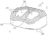
도 1은 본 발명의 일 실시예에 따른 추체간 유합술용 케이지 어셈블리의 전체적인 구조를 나타낸 사시도
도 2는 본 발명의 일 실시예에 따른 추체간 유합술용 케이지 어셈블리를 추체와 이웃한 추체 사이에 시술한 것을 나타낸 측면 개념도
도 3은 본 발명의 일 실시예에 따른 추체간 유합술용 케이지 어셈블리의 평면 개념도
도 4는 본 발명의 다른 실시예에 따른 추체간 유합술용 케이지 어셈블리를 추체와 이웃한 추체 사이에 시술한 것을 나타낸 평면 개념도
도 5는 본 발명의 다른 실시예에 따른 추체간 유합술용 케이지 어셈블리의 사시도
도 6은 본 발명의 다른 실시예에 따른 추체간 유합술용 케이지 어셈블리의 측면 개념도
도 7은 본 발명의 또 다른 실시예에 따른 추체간 유합술용 케이지 어셈블리를 추체와 이웃한 추체 사이에 시술한 것을 나타낸 평면 개념도
도 8은 본 발명의 또 다른 실시예에 따른 추체간 유합술용 케이지 어셈블리의 사시도
도 9는 본 발명의 또 다른 실시예에 따른 추체간 유합술용 케이지 어셈블리의 측면 개념도
도 10은 본 발명의 기타 실시예에 따른 추체간 유합술용 케이지 어셈블리의 평면 개념도1 is a perspective view showing the overall structure of a cage assembly for interbody fusion according to an embodiment of the present invention;
FIG. 2 is a side conceptual view showing a cage assembly for interbody fusion according to an embodiment of the present invention between a vertebra and a neighboring vertebra
3 is a plan view of a cage assembly for interbody fusion according to an embodiment of the present invention.
FIG. 4 is a plan view showing a cage assembly for interbody fusion according to another embodiment of the present invention,
5 is a perspective view of a cage assembly for interbody fusion according to another embodiment of the present invention.
6 is a side elevational view of a cage assembly for interbody fusion according to another embodiment of the present invention
FIG. 7 is a plan view showing a cage assembly for interbody fusion according to another embodiment of the present invention between a vertebral body and a neighboring vertebra
8 is a perspective view of a cage assembly for interbody fusion according to another embodiment of the present invention
9 is a side elevational view of a cage assembly for interbody fusion according to another embodiment of the present invention
10 is a plan view of a cage assembly for interbody fusion according to another embodiment of the present invention
본 발명의 이점 및 특징, 그리고 그것들을 달성하는 방법은 첨부되는 도면과 함께 상세하게 후술되어 있는 실시예를 참조하면 명확해질 것이다.BRIEF DESCRIPTION OF THE DRAWINGS The advantages and features of the present invention, and how to accomplish them, will become apparent by reference to the embodiments described in detail below with reference to the accompanying drawings.
그러나 본 발명은 여기서 설명되는 실시예에 한정되지 않고 다른 형태로 구체화될 수도 있다.However, the present invention is not limited to the embodiments described herein but may be embodied in other forms.
오히려, 여기서 소개되는 실시예는 개시된 내용이 철저하고 완전해질 수 있도록 그리고 당업자에게 본 발명의 사상이 충분히 전달될 수 있도록 하기 위해 제공되는 것이다.Rather, the embodiments disclosed herein are provided so that the disclosure can be thorough and complete, and will fully convey the scope of the invention to those skilled in the art.
도면들에 있어서, 층 및 영역들의 두께는 명확성을 기하기 위하여 과장된 것이다.In the drawings, the thicknesses of layers and regions are exaggerated for clarity.
상단, 하단, 상면, 하면, 또는 상부, 하부 등의 용어는 구성요소에 있어 상대적인 위치를 구별하기 위해 사용되는 것이다.Terms such as top, bottom, top, bottom, or top, bottom, etc. are used to distinguish relative positions in components.
예를 들어, 편의상 도면상의 위쪽을 상부, 도면상의 아래쪽을 하부로 명명하는 경우, 실제에 있어서는 본 발명의 권리 범위를 벗어나지 않으면서 상부는 하부로 명명될 수 있고, 하부는 상부로 명명될 수 있다.For example, in the case of naming the upper part of the drawing as upper part and the lower part as lower part in the drawings for convenience, the upper part may be named lower part and the lower part may be named upper part without departing from the scope of right of the present invention .
본 출원에서 사용한 용어는 단지 특정한 실시예를 설명하기 위해 사용된 것으로, 본 발명을 한정하려는 의도가 아니다.The terminology used in this application is used only to describe a specific embodiment and is not intended to limit the invention.
단수의 표현은 문맥상 명백하게 다르게 뜻하지 않는 한, 복수의 표현을 포함한다.The singular expressions include plural expressions unless the context clearly dictates otherwise.
본 출원에서, "포함하다" 또는 "가지다" 등의 용어는 명세서상에 기재된 특징, 숫자, 단계, 동작, 구성요소, 부분품 또는 이들을 조합한 것이 존재함을 지정하려는 것이지, 하나 또는 그 이상의 다른 특징들이나 숫자, 단계, 동작, 구성요소, 부분품 또는 이들을 조합한 것들의 존재 또는 부가 가능성을 미리 배제하지 않는 것으로 이해되어야 한다.In this application, the terms "comprises", "having", and the like are used to specify that a feature, a number, a step, an operation, an element, a part or a combination thereof is described in the specification, But do not preclude the presence or addition of one or more other features, integers, steps, operations, components, parts, or combinations thereof.
다르게 정의되지 않는 한, 기술적이거나 과학적인 용어를 포함해서 여기서 사용되는 모든 용어들은 본 발명이 속하는 기술 분야에서 통상의 지식을 가진 자에 의해 일반적으로 이해되는 것과 동일한 의미가 있다.Unless otherwise defined, all terms used herein, including technical or scientific terms, have the same meaning as commonly understood by one of ordinary skill in the art to which this invention belongs.
일반적으로 사용되는 사전에 정의되어 있는 것과 같은 용어들은 관련 기술의 문맥상 가지는 의미와 일치하는 의미가 있는 것으로 해석되어야 하며, 본 출원에서 명백하게 정의하지 않는 한, 이상적이거나 과도하게 형식적인 의미로 해석되지 않는다.Terms such as those defined in commonly used dictionaries are to be interpreted as having a meaning consistent with the meaning in the context of the relevant art and are to be construed as ideal or overly formal in meaning unless explicitly defined in the present application Do not.
이하, 본 발명의 바람직한 실시예를 첨부도면에 의거하여 상세하게 설명하기로 한다.Hereinafter, preferred embodiments of the present invention will be described in detail with reference to the accompanying drawings.
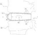
도 1은 본 발명의 일 실시예에 따른 추체간 유합술용 케이지 어셈블리의 전체적인 구조를 나타낸 사시도이며, 도 2는 본 발명의 일 실시예에 따른 추체간 유합술용 케이지 어셈블리를 추체와 이웃한 추체 사이에 시술한 것을 나타낸 측면 개념도이고, 도 3은 본 발명의 일 실시예에 따른 추체간 유합술용 케이지 어셈블리의 평면 개념도이다.FIG. 1 is a perspective view showing the overall structure of a cage assembly for interbody fusion according to an embodiment of the present invention. FIG. 2 is a cross-sectional view of a cage assembly for interbody fusion according to an embodiment of the present invention, FIG. 3 is a schematic plan view of a cage assembly for interbody fusion according to an embodiment of the present invention. Referring to FIG.
참고로, 도 1 내지 도 3에서 투명한 화살표는 본체(10)가 삽입되는 방향을 나타내는 것이다.For reference, the transparent arrows in FIGS. 1 to 3 indicate the direction in which the
그리고, 도 1 내지 도 9에서 미설명 부호로 'f'는 '전방측'을, 'r'은 '후방측'을 각각 나타낸다.1 to 9, 'f' denotes 'front side', and 'r' denotes rear side.
본 발명은 도시된 바와 같이 본체(10)에 제1, 2 나사부(21, 22) 및 공간부(30)가 형성된 구조임을 파악할 수 있다.It can be understood that the present invention is a structure in which the first and
본체(10)는 디스크가 제거된 척추의 추체(50)와 이웃한 추체(50') 사이에 삽입되는 것으로, 손상된 디스크가 차지하던 추체(50)와 이웃한 추체(50') 사이의 공간을 대체하는 것이다.The
제1 나사부(21)는 본체(10)의 상면에 형성되는 것으로, 중심으로부터 바깥쪽을 향하여 제1 방향을 따라 나선 형상으로 형성되는 것이며, 제2 나사부(22)는 본체(10)의 하면에 형성되는 것으로, 중심으로부터 바깥쪽을 향하여 제2 방향을 따라 나선 형상으로 형성되는 것이다.The
한편, 공간부(30)는 본체(10)의 상면 및 하면을 관통하여 형성되고, 추체(50)와 이웃한 추체(50')를 형성하는 뼈가 상호 융합되도록 하는 공간이다.The
따라서, 본 발명은 척추를 구성하는 이웃한 두 개의 추체(50, 50') 또는 그 이상의 추체들을 상호 융합시키는 수술시 편의를 제공할 수 있게 된다.Therefore, the present invention can provide convenience in operation of mutually fusing two
본 발명은 상기와 같은 실시예의 적용이 가능하며, 다음과 같은 실시예의 적용 또한 가능함은 물론이다.The present invention can be applied to the embodiment described above, and it goes without saying that the following embodiments are also applicable.
제1 나사부(21)의 제1 방향과, 제2 나사부(22)의 제2 방향은 상호 반대 방향이 되도록 하거나, 상호 같은 방향으로 형성되도록 할 수도 있다.The first direction of the
여기서, 제1 방향과 제2 방향은 상호 반대 방향으로 형성되도록 하여, 시술후 본체(10)가 추체(50)와 이웃한 추체(50') 사이로부터 이탈되는 위험을 미연에 방지하고, 본 발명에 따른 케이지 어셈블리, 즉 본체(10)가 추체(50)와 이웃한 추체(50') 사이에서 본체(10) 자체의 고정력(self-fixation)을 갖기 위한 것이다.Here, the first direction and the second direction are formed in mutually opposite directions to prevent the risk that the
즉, 제1 방향과 제2 방향이 반대가 되면, 시술후 척추의 회전 운동시 추체(50)와 이웃한 추체(50') 사이에 본체(10)가 삽입된 후, 본체(10)의 상면 및 하면에 형성된 제1, 2 나사부(21, 22)가 추체(50, 50') 내로 삽입되면서 본체(10)가 추체(50)와 이웃한 추체(50') 사이에서 자체적인 고정력(self-fixation)을 가지게 되는 것이다.That is, when the first direction and the second direction are reversed, the
예를 들어, 제1 방향이 시계 방향이라면, 시계 방향을 따라 형성된 제1 나사부(21)에 대하여 제2 나사부(22)는 반시계 방향을 따라 형성되므로, 제2 방향은 반시계 방향이 될 것이다.For example, if the first direction is the clockwise direction, the
또한, 제1 방향이 반시계 방향이라면, 반시계 방향을 따라 형성된 제1 나사부(21)에 대하여 제2 나사부(22)는 시계 방향을 따라 형성되므로, 제2 방향은 시계 방향이 될 것이다.If the first direction is the counterclockwise direction, the
다시 말해, 전술한 제1, 2 나사부(21, 22)의 제1, 2 방향은 본체(10) 자체가 추체(50)와 이웃한 추체(50') 사이에서 자체적인 고정 기능을 수행하면서 추체(50)와 이웃한 추체(50') 상호간의 골유합(bone graft)을 촉진시키며, 추가적인 척추 고정기기 등의 사용을 저감시키기 위한 기술적인 수단이라 할 수 있다.In other words, the first and second directions of the first and second threaded
여기서, 자체적인 고정력(self-fixation)이라 함은, 본체(10)가 추체(50)와 이웃한 추체(50') 사이에 삽입된 후에도 추체(50)와 이웃한 추체(50')가 상호 미세한 회전 운동이 일어나게 되므로, 이러한 미세한 회전 운동이 발생하면 제1, 2 나사부(21, 22)가 추체(50)와 이웃한 추체(50') 내로 삽입되면서 추체(50)와 이웃한 추체(50') 상호간에 일어나는 미세한 회전 운동을 방지하는 고정력을 발생시키는 것을 말한다.Here, self-fixation refers to self-fixation in which after the
즉, 척추 수술에서는 골유합을 위하여 케이지를 이용한 추체간 삽입술과 같은 고정술을 실시할 경우에 고정술을 실시한 이후에도 척추에서 발생하는 미세 운동을 최소화하거나 방지하는 시술이 된 경우 골유합이 촉진되는 것이다.In spinal surgery, the bony union is promoted when minimally minimizing or preventing micro-movement occurring in the vertebrae even after fixation such as cervical interbody fusion using cage for bony union.
따라서, 이러한 자체적인 고정력은 추체(50)와 이웃한 추체(50')의 골유합을 촉진시키는 역할을 하게 되는 것이다. 본체(10)의 상면과 하면은 도 2와 같이 각각 추체(50)와 이웃한 추체(50')가 상호 마주 보는 면들과 각각 대면하도록 배치되어 본체(10)가 추체(50)와 이웃한 추체(50')로부터 이탈되지 않도록 한다.Therefore, this self-fixing force promotes the union of the
또한, 본체(10)의 상면과 하면은 추체(50)와 이웃한 추체(50') 사이에 세워져 삽입될 수도 있음은 물론이다.It goes without saying that the upper surface and the lower surface of the
이러한, 본체(10)의 전방 상면은 도 2와 같이 라운드지게 하향 경사지고, 본체(10)의 전방 하면은 라운드지게 상향 경사지면서 상호 대칭을 이루며, 본체(10)는 디스크가 제거된 환자의 배부(背部)측으로부터 삽입되는 것으로, 후방추체 유합술(Posterial Lumbar Interbody Fusion, 이하 PLIF)에 적용될 수 있을 것이다.2, the front lower surface of the
또한, 이러한 본체(10)의 전방 상, 하면의 구조는 PLIF 뿐만 아니라 횡추간공 유합술(Transforaminal Lumbar Interbody Fusion, TLIF)이나 전측방(anterolateral) 또는 사측면방(oblique-lateral) 요추부 추체간 유합술(Anterolateral Lumbar Interbody Fusion, ALIF 또는 Oblique-lateral Lumbar Interbody Fusion, OLIF), 요추부 측방 추체간 유합술(Direct lateral Lumbar Interbody Fusion, DLIF) 등에도 공통적으로 적용될 수 있음은 물론이다.In addition, the anterior and lower surface structures of the
여기서, 상호 대칭을 이루는 본체(10)의 전방 상면과 전방 하면이 이루는 경사각도는 각각 0도, 4도, 8도 내외가 되도록 함으로써, 척추의 후만각(lordotic angle)에 적합하도록 설계할 수도 있음은 물론이다.Here, the inclination angles formed between the front upper surface and the front lower surface of the
통상, 인체의 척추는 경추부의 경우 후만(lordosis)의 형태를, 흉추부의 경우 전만(kyphosis)의 형태를, 요추부의 경우 후만(lordosis)의 형태를 하고 있으므로, 본체(10)의 전방 상면과 전방 하면이 이루는 경사각도는 전술한 범위 내에서 적절히 선택 설계가 가능할 것이다.Since the vertebra of the human body is in the form of lordosis in the case of the cervical vertebra, kyphosis in the case of the thoracic vertebra and lordosis in the case of the lumbar vertebra, The inclination angle formed by the lower surface can be appropriately selected and designed within the above-mentioned range.
따라서, 본체(10)는 PLIF를 실시할 때, 디스크가 제거된 환자의 배부측, 또는 환자의 후방이나 횡추간공측 방향으로부터 추체(50)와 이웃한 추체(50') 사이에 하나 또는 한 쌍씩 이격 배치된다.Therefore, when the PLIF is performed, the
그리고, 도 3을 참조하면, 상면 또는 하면에 형성된 공간부(30)가 이루는 면적은 본체(10)의 상면 또는 하면의 20 내지 80%가 되도록 하며, 이러한 공간부(30)가 이루는 면적은 추체(50)와 이웃한 추체(50') 사이의 골조직 형성 및 유합후 구조적인 강도를 유지하기 위한 최적의 면적 범위라 할 수 있다.3, the area formed by the
그리고, 본체(10)가 삽입되는 방향의 양측면에는, 공간부(30)와 상호 연통되도록 적어도 하나 이상의 슬롯(35)이 관통 형성되는 것이 바람직하다.It is preferable that at least one
슬롯(35)은 추체간의 유합술을 실시하고 나서 일정 시간이 경과한 후 본체(10) 내부의 공간부(30)에 추체(50)와 이웃한 추체(50') 사이의 골조직이 형성되어 골유합이 이루어졌는지의 여부를 방사선 검사를 이용하여 확인하기 위한 것이다.The
그리고, 본체(10)는 도 3과 같이 본체(10)가 삽입되는 방향의 양측면이 볼록하게 유선형으로 형성되도록 하고, 이러한 유선형의 양측면 구조는 디스크가 제거된 환자의 배부측으로부터 추체(50)와 이웃한 추체(50') 사이에 원활하게 삽입될 수 있도록 하는 것이다.3, both side surfaces of the
또한, 본체(10)가 삽입되는 방향에 따른 길이(ℓ1)는, 본체(10)가 삽입되는 방향과 직교하는 방향에 따른 폭(w1)보다 길게 형성되도록 함으로써, 본체가 삽입되는 방향의 양측면이 볼록한 구조와 함께 전체적으로 길쭉한 탄환 형상이 되도록 함으로써, 추체(50)와 이웃한 추체(50') 사이에 원활하게 삽입될 수 있다.The length l1 along the direction in which the
폭(w1)과 길이(ℓ1)의 비는 더욱 바람직하게는 1:1.2 내지 1:2 또는 적절한 범위 내에서 변형 및 응용 설계가 가능함은 물론이다.It is needless to say that the ratio of the width w1 to the length l1 is more preferably from 1: 1.2 to 1: 2, or the modification and application design can be performed within an appropriate range.
또한, 제1 나사부(21)와 제2 나사부(22)의 중심은 본체(10)의 중심과 동일하도록 하거나 각각 다른 부위에 배치되도록 하여 추체(50)와 이웃한 추체(50') 사이에 안정적으로 본체(10)가 안착되어 골조직의 형성 및 추체(50)와 이웃한 추체(50')의 상호 골유합이 이루어질 수 있는 것이다.The centers of the
또한, 제1, 2 나사부(21, 22)의 중심이 본체(10)의 외부에 배치됨으로써, 추체(50)와 이웃한 추체(50') 사이에 삽입된 본체(10)의 위치에 따라서 본체(10)의 제1, 2 나사부(21, 22)가 추체(50)와 이웃한 추체(50')에 적절히 삽입되면서 고정력을 얻어 골유합이 이루어질 수 있는 것이다.The center of the first and
따라서, 본 발명의 일 실시예에 따른 추체간 유합술용 케이지 어셈블리의 본체(10)를 환자의 배부측 또는 환자의 추체간으로부터 삽입하되, 추체(50)와 이웃한 추체(50') 사이에서 손상된 디스크를 제거한 후, 디스크가 제거된 이 공간에 한 쌍의 본체(10)를 삽입하여 추체(50)와 이웃한 추체(50')를 상호 유합(fusion)시키게 되는 것이다.Therefore, the
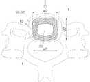
한편, 본 발명은 전술한 바와 같은 도 1 내지 도 3의 실시예에 따른 PLIF에도 적용할 수 있으며, 도 4 내지 도 6과 같은 전방 경추체 유합술(Anterior Cervical Interbody Fusion, 이하 ACIF)에도 적용되는 구조의 실시예를 적용할 수도 있다.The present invention can be applied to the PLIF according to the embodiments of FIGS. 1 to 3 as described above, and can be applied to anterior cervical interbody fusion (ACIF) as shown in FIGS. May be applied.
즉, 본체(10)는 도 4와 같이 ACIF를 실시할 때 디스크가 제거된 환자의 경부(經部) 전방측으로부터 삽입되는 것이다.That is, the
본체(10)의 상면에 형성된 제1 나사부(21)와 하면에 형성된 제2 나사부(22)는 상호 반대 방향으로 형성되도록 하여, 시술후 본체(10)가 추체(50)와 이웃한 추체(50') 사이로부터 이탈되는 위험을 미연에 방지하고, 본체(10)가 추체(50)와 이웃한 추체(50') 사이에서 고정력을 갖게 된다.The
제1 나사부(21)와 제2 나사부(22)는 전술한 바와 같이 상호 반대 방향으로 형성할 수도 있음은 물론, 같은 방향으로도 형성되게 할 수 있다.The
그리고, 본체(10)는 삽입되는 방향을 기준으로 전방측의 폭(w2)이 후방측의 폭(w2')에 비하여 넓으며, 이것은 환자의 경부 전방측으로부터 원활하게 삽입되도록 하기 위한 기술적 수단이다.The width w2 of the front side is larger than the width w2 'of the rear side on the basis of the insertion direction of the
그리고, 공간부(30)의 중심은 추체(50)와 이웃한 추체(50') 사이에 본체(10)가 안정적으로 안착 배치될 수 있도록 본체(10)의 상면 또는 하면의 중심과 일치되도록 하는 것이 바람직하다.The center of the
다시말해, 본체(10)의 상면 또는 하면과, 공간부(30)는 삽입되는 방향을 기준으로 후방측에서 전방측으로 갈수록 점차 좁아지게 형성되도록 한다.In other words, the upper surface or the lower surface of the
본체(10)의 상면과 하면은 도 4와 같이 각각 추체(50)와 이웃한 추체(50')가 상호 마주 보는 면들과 각각 대면하게 되고, 상면 또는 하면에 형성된 공간부(30)가 이루는 면적은 본체(10)의 상면 또는 하면의 20 내지 80%가 되도록 한다.As shown in FIG. 4, the upper and lower surfaces of the
이러한 공간부(30)가 이루는 면적은 추체(50)와 이웃한 추체(50') 사이의 골조직 형성 및 융합후 구조적인 강도를 유지하기 위한 최적의 면적 범위라 할 수 있다.The area formed by the
또한, 본체(10)가 삽입되는 방향에 따른 길이(ℓ2)는, 후방측의 폭(w2)보다 짧거나 같게 형성되어지되, 길이(ℓ2)와 후방측의 폭(w2)의 비는 대략 1:1.1 내지 1:2의 범위 내에서 적절한 비율로 응용 및 변형 설계가 가능함은 물론이다.The length l2 along the direction in which the
이러한 비율과 폭과 길이의 구조는 추체(50)와 이웃한 추체(50')가 마주보는 면이 대략 후방측의 폭(w2')에 비하여 전방측의 폭(w2)이 넓은 본체(10)의 상면 및 하면 형상에 대응되기 때문이며, 비교적 넓은 면적에 걸쳐 구조적 강도를 유지하면서 추체(50)와 이웃한 추체(50')를 지지하고 골조직을 형성하여 상호 유합이 이루어지도록 하기 위한 것이다.The ratio, width, and length of the
그리고, 본체(10)의 전방 상면은 도 5 및 도 6과 같이 제1 각도(a)로 라운드지게 하향 경사지고, 본체(10)의 후방 하면은 제1 각도(a)보다 작거나 같은 제2 각도(b)로 라운드지게 상향 경사지면서 유선형을 이룬다.The front upper surface of the
통상, 제1 각도(a)는 제2 각도(b) 보다 크게 형성되도록 하며, 바람직하게는 3배 내외가 되도록 하며, 제2 각도(b)가 제1 각도(a)보다 작은 것은 측면에서 보아 전체적으로 경추부의 형태가 'C'자 형상으로 구부러지게 배치되는, 즉 후만의 형태를 이루도록 경추의 구조적 특성상 추체(50)와 이웃한 추체(50')가 자연스런 배열 상태를 유지하기 위한 것이다.Generally, the first angle a is formed to be larger than the second angle b, preferably three times, and the second angle b is smaller than the first angle a, The
즉, 요추 하부의 후만각(lordotic angle)과 추체(50)와 이웃한 추체(50')의 해부학적 특징 때문에 PLIF나 후술할 ALIF용의 본체(10)와 달리 본체(10)의 전방 상면과 전방 하면이 상호 비대칭이 되도록 하는 것이다.That is, unlike the PLIF or the
또한, 이러한 본체(10)의 전방 상, 하면의 구조는 PLIF 뿐만 아니라 횡추간공 추체간 유합술(Transforaminal Lumbar Interbody Fusion, TLIF)이나 전측방(anterolateral) 또는 사측면방(oblique-lateral) 요추부 추체간 유합술(Anterolateral Lumbar Interbody Fusion, ALIF 또는 Oblique-lateral Lumbar Interbody Fusion, OLIF), 요추부 측방 추체간 유합술(Direct lateral Lumbar Interbody Fusion, DLIF) 등에도 공통적으로 적용될 수 있음은 물론이다.The structure of the anterior-superior and inferior surfaces of the
아울러, 본 발명의 다른 실시예에 따른 추체간 유합술용 케이지 어셈블리는 도 4 및 도 5에서 제1 나사부(21) 또는 제2 나사부(22)의 중심이 본체(10)의 상면 또는 하면의 중심과 어긋나게 배치된 것으로 도시하고 있으나, 반드시 이러한 구조에 국한되지는 않는다.4 and 5, the center of the
구체적으로는, 제1 나사부(21) 또는 제2 나사부(22)의 중심은 본체(10)의 상면 또는 하면의 중심과 일치하도록 하거나, 상면 또는 하면의 전방측 가장자리로부터 본체(10)가 삽입되는 방향에 따른 길이의 1/3이 되는 지점에 형성되도록 하거나, 본체(10)의 상면 또는 하면의 후방측으로부터 이격되게 형성되도록 하거나, 제1, 2 나사부(21, 22)의 중심이 본체(10)의 내부 또는 외부에 배치되도록 하는 등의 응용 및 변형 설계가 가능함은 물론이다.Specifically, the center of the
따라서, 본 발명의 다른 실시예에 따른 추체간 유합술용 케이지 어셈블리의 본체(10)를 환자의 경부 전방측으로부터 삽입하되, 추체(50)와 이웃한 추체(50') 사이에서 손상된 디스크를 제거한 후, 디스크가 제거된 이 공간에 본체(10)를 삽입한 다음, 환자의 골반에서 골편(이하 미도시), 즉 자가골(自家骨)을 채취하거나, 인공적으로 제조된 골 대체재 또는 동종골(同種骨) 등을 공간부(30)에 넣으면, 추체(50)와 이웃한 추체(50')는 골편을 매개로 하여 상호 유합(fusion)되는 것이다.Therefore, the
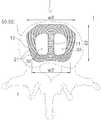
한편, 본 발명은 전술한 바와 같은 도 1 내지 도 3의 실시예에 따른 PLIF에도 적용할 수 있으며, 도 4 내지 도 6과 같은 ACIF에도 적용할 수 있고, 도 7 내지 도 9와 같은 전방추체 유합술(Anterior Lumbar Interbody Fusion, 이하 ALIF)에도 적용할 수 있으며, 이외에도 횡추간공 추체간 유합술(transforaminal Lumbar Interbody Fusion, TLIF)이나 전측방(anterolateral) 또는 사측면방(oblique-lateral) 요추부 추체간 유합술(Anterolateral Lumbar Interbody Fusion, ALIF 또는 Oblique-lateral Lumbar Interbody Fusion, OLIF), 요추부 측방 추체간 유합술(Direct lateral Lumbar Interbody Fusion, DLIF) 등에도 공통적으로 적용될 수 있음은 물론이다.The present invention can be applied to the PLIF according to the embodiment of FIGS. 1 to 3 as described above, and can also be applied to the ACIF as shown in FIGS. 4 to 6, (LIFT) and anterior lumbar interbody fusion (ALIF). In addition, transforaminal lumbar interbody fusion (TLIF), anterolateral or oblique-lateral lumbar interbody fusion It is of course also applicable to interbody fusion, ALIF or oblique-lateral lumbar interbody fusion (OLIF), and direct lateral lumbar interbody fusion (DLIF).
즉, 본체(10)는 도 7과 같이 ALIF를 실시할 때 디스크가 제거된 환자의 전방 또는 환자의 복부(腹部) 또는 후복막(後腹膜)측으로부터 삽입되는 것이다.That is, the
그리고, 본체(10)는 삽입되는 방향을 기준으로 전방측의 폭(w3)이 후방측의 폭(w3')에 비하여 넓으며, 이것은 환자의 요추부 전방측으로부터 원활하게 삽입되도록 하기 위한 기술적 수단이다.The width w3 of the front side is larger than the width w3 'of the rear side on the basis of the insertion direction of the
그리고, 공간부(30)의 중심은 추체(50)와 이웃한 추체(50') 사이에 본체(10)가 안정적으로 안착 배치될 수 있도록 본체(10)의 상면 또는 하면의 중심과 일치되도록 하는 것이 바람직하다.The center of the
다시 말해, 본체(10)의 상면 또는 하면과, 공간부(30)는 삽입되는 방향을 기준으로 전방측에서 후방측으로 갈수록 점차 좁아지게 형성되도록 한다.In other words, the upper surface or the lower surface of the
본체(10)의 상면과 하면은 도 7과 같이 각각 추체(50)와 이웃한 추체(50')가 상호 마주 보는 면들과 각각 대면하게 되고, 상면 또는 하면에 형성된 공간부(30)가 이루는 면적은 본체(10)의 상면 또는 하면의 20 내지 80%가 되도록 한다.The upper surface and the lower surface of the
이러한 공간부(30)가 이루는 면적은 추체(50)와 이웃한 추체(50') 사이의 골조직 형성 및 유합후 구조적인 강도를 유지하기 위한 최적의 면적 범위라 할 수 있다.The area formed by the
그리고, 본체(10)가 삽입되는 방향을 따라 공간부(30)를 복수로 구획하도록 본체(10)에 형성되는 격벽부(11)를 더 포함하는 구조의 실시예를 적용할 수도 있을 것이다.The present invention may also be applied to a structure including a
이러한 격벽부(11)는 본체(10)의 구조적 안정성을 도모하고, 제1, 2 나사부(21, 22)의 중심이 추체(50)와 이웃한 추체(50') 사이에 안정적으로 고정되도록 하기 위한 것이다.The
또한, 본체(10)가 삽입되는 방향에 따른 길이(ℓ3)는, 전방측의 폭(w3)보다 짧게 형성되어지되, 길이(ℓ3)와 후방측의 폭(w3)의 비는 대략 1:1.1 내지 1:2의 범위 내에서 적절한 비율로 응용 및 변형 설계가 가능함은 물론이다.The length l3 along the direction in which the
이러한 비율과 폭과 길이의 구조는 추체(50)와 이웃한 추체(50')가 마주보는 면이 대략 후방측의 폭(w3')에 비하여 전방측의 폭(w3)이 넓은 본체(10)의 상면 및 하면 형상에 대응되기 때문이며, 비교적 넓은 면적에 걸쳐 구조적 강도를 유지하면서 추체(50)와 이웃한 추체(50')를 지지하고 골조직을 형성하여 상호 유합이 이루어지도록 하기 위한 것이다.The ratio, width, and length of the
그리고, 본체(10)의 전방 상면은 도 8 및 도 9와 같이 라운드지게 하향 경사지고, 본체(10)의 전방 하면은 라운드지게 상향 경사지면서 상호 대칭을 이루며 전체적으로 볼록한 상면 및 하면의 형상을 이루어 ALIF를 실시할 때 추체(50)와 이웃한 추체(50') 사이에 본체(10)가 원활하게 삽입될 수 있게 된다.The front upper surface of the
아울러, 본 발명의 다른 실시예에 따른 추체간 유합술용 케이지 어셈블리는 도 7 내지 도 9에서 제1 나사부(21) 또는 제2 나사부(22)의 중심이 본체(10)의 상면 또는 하면의 중심에 대하여 서로 어긋나게 배치되는 것으로 도시하고 있으나, 반드시 이러한 구조에 국한되지는 않는다.7 to 9, the center of the
구체적으로는, 제1 나사부(21) 또는 제2 나사부(22)의 중심은 본체(10)의 상면 또는 하면의 중심과 일치하도록 하거나, 상면 또는 하면의 후방측 가장자리로부터 본체(10)가 삽입되는 방향에 따른 길이의 1/3이 되는 지점에 형성되도록 하거나, 본체(10)의 상면 또는 하면의 후방측으로부터 이격되게 하거나, 제1, 2 나사부(21, 22)의 중심이 본체(10)의 내부나 외부에 위치할 수 있게 형성되도록 하는 등의 응용 및 변형 설계가 가능함은 물론이다.Specifically, the center of the
따라서, 본 발명의 또 다른 실시예에 따른 추체간 유합술용 케이지 어셈블리의 본체(10)를 환자의 전방 또는 복부측으로부터 삽입하되, 추체(50)와 이웃한 추체(50') 사이에서 손상된 디스크를 제거한 후, 디스크가 제거된 이 공간에 본체(10)를 삽입한 다음, 환자의 골반에서 골편(이하 미도시) , 즉 자가골(自家骨)을 채취하거나, 인공적으로 제조된 골 대체재, 동종골 등을 공간부(30)에 넣으면, 추체(50)와 이웃한 추체(50')는 골편을 매개로 하여 상호 유합(fusion)되는 것이다.Therefore, the
이상과 같이 본 발명은 척추를 구성하는 이웃한 추체의 일부를 제거한 부위나, 두 개의 추체 또는 그 이상의 추체들을 상호 융합시키는 수술시 편의를 도모하기 위한 추체간 유합술용 케이지 어셈블리를 제공하는 것을 기본적인 기술적 사상으로 하고 있음을 알 수 있다.As described above, the present invention provides a cage assembly for interbody fusion for the purpose of facilitating surgery at the site where a part of the adjacent vertebrae constituting the vertebrae is removed or the two vertebrae or more vertebrae are fused together. It is understood that it is thought.
그리고, 본 발명의 기본적인 기술적 사상의 범주 내에서 당해 업계 통상의 지식을 가진 자에게 있어서는 본 발명의 다양한 실시예에 따른 추체간 유합술용 케이지 어셈블리를 전술한 바와 같은 PLIF, ACIF, ALIF 외에도 횡추간공 추체간 유합술(Transforaminal Lumbar Interbody Fusion; TLIF)이나 전측방(anterolateral) 또는 사측면방(oblique-lateral) 요추부 추체간 유합술(Anterolateral Lumbar Interbody Fusion;ALIF 또는 Oblique-lateral Lumbar Interbody Fusion, OLIF) 등에도 적용할 수 있다.In addition, within the scope of the basic technical idea of the present invention, those skilled in the art will appreciate that the cage assembly for intervertebral fusion according to various embodiments of the present invention can be combined with PLIF, ACIF, ALIF, It can also be applied to Transforaminal Lumbar Interbody Fusion (TLIF), anterolateral or oblique-lateral lumbar interbody fusion (ALIF or Oblique-lateral Lumbar Interbody Fusion, OLIF) have.
또한, 본 발명은 도 10과 같이 본체(10)의 길이 방향을 따라 복수의 공간부(30)가 형성되고, 각각의 공간부(30) 주변에 제1 나사부(21)와 제2 나사부(22)가 형성되며, 본체(10)의 전방 및 후방 상면은 라운드지게 하향 경사지고, 본체(10)의 전방 및 후방 하면은 라운드지게 상향 경사지면서 상호 대칭을 이루는 것을, 요추부 측방 추체간 유합술(Direct lateral Lumbar Interbody Fusion, DLIF) 등에도 폭넓게 적용할 수 있다.10, a plurality of
여기서, 본체(10)에는 도시된 바와 같이 공간부(30)를 복수로 구획하는 격벽부(11)가 더 구비되도록 할 수도 있다.Here, the
이때, 제1 나사부(21)와 제2 나사부(22)의 중심은, 도 10(a) 및 도 10(b)와 같이 격벽부(11)에 배치되도록 하거나, 특별히 도시하지는 않았지만 공간부(30)의 중심과 동일하거나, 공간부(30)의 내부 또는 외부에 배치되거나, 본체(10)의 내부 또는 외부에 배치되도록 할 수 있는 등 다른 많은 변형 및 응용 또한 가능함은 물론이다.
At this time, the centers of the
10...본체
11...격벽부
21...제1 나사산부
22...제2 나사산부
30...공간부
35...슬롯
50...추체
50'...추체(50)와 이웃한 추체10 ... body
11:
21 ... first thread portion
22 ... second thread portion
30 ... space portion
35 ... slot
Fifty ...
50 '... the
Claims (18)
Translated fromKorean상기 본체의 상면에 형성되는 것으로, 중심으로부터 바깥쪽을 향하여 제1 방향을 따라 나선 형상으로 형성되는 제1 나사부;
상기 본체의 하면에 형성되는 것으로, 중심으로부터 바깥쪽을 향하여 제2 방향을 따라 나선 형상으로 형성되는 제2 나사부; 및
상기 본체의 상면 및 하면을 관통하여 형성되고, 상기 추체와 상기 이웃한 추체를 형성하는 뼈가 상호 융합되도록 하는 공간부;를 포함하며,
상기 제1 방향과 상기 제2 방향은 상호 같은 방향 또는 반대 방향이고,
상기 제1 나사부와 상기 제2 나사부의 중심은 상기 본체의 중심과 동일하거나, 상기 본체 상, 하면의 각각 서로 다른 위치에 배치되는 것을 특징으로 하는 추체간 유합술용 케이지 어셈블리.
A body inserted between the vertebrae of the vertebrae from which the disc has been removed and the adjacent vertebrae;
A first screw portion formed on an upper surface of the main body and formed in a spiral shape along a first direction from the center toward the outside;
A second screw portion formed on a lower surface of the main body and formed in a spiral shape along a second direction from the center toward the outside; And
And a space formed to penetrate an upper surface and a lower surface of the main body so that the vertebrae and the bones forming the adjacent vertebrae are mutually fused,
Wherein the first direction and the second direction are the same or opposite directions,
Wherein a center of the first threaded portion and a side of the second threaded portion are the same as the center of the main body or are disposed at different positions on the main body and the lower face of the main body.
상기 본체의 전방 상면은 라운드지게 하향 경사지고, 상기 본체의 전방 하면은 라운드지게 상향 경사지면서 상호 대칭을 이루며, 상기 본체는 상기 디스크가 제거된 환자의 추체와 이웃한 추체 사이로부터 삽입되는 것을 특징으로 하는 추체간 유합술용 케이지 어셈블리.
The method according to claim 1,
Wherein a front upper surface of the main body is roundly inclined downward and a front lower surface of the main body is rounded upward to be mutually symmetrical and the main body is inserted between a vertebra of a patient from which the disc is removed and an adjacent vertebra A cage assembly for interbody fusion.
상기 본체는,
상기 본체가 삽입되는 방향의 양측면이 볼록하게 유선형으로 형성되는 것을 특징으로 하는 추체간 유합술용 케이지 어셈블리.
The method according to claim 1,
The main body includes:
Wherein both side surfaces in a direction in which the main body is inserted are convex and formed in a streamlined shape.
상기 본체가 삽입되는 방향에 따른 길이는, 상기 본체가 삽입되는 방향과 직교하는 방향에 따른 폭보다 길게 형성되는 것을 특징으로 하는 추체간 유합술용 케이지 어셈블리.
The method according to claim 1,
Wherein a length along the insertion direction of the main body is longer than a width along a direction orthogonal to a direction in which the main body is inserted.
상기 제1 나사부와 상기 제2 나사부의 중심은 상기 본체의 내부 또는 외부에 배치되는 것을 특징으로 하는 추체간 유합술용 케이지 어셈블리.
The method according to claim 1,
And the center of the first threaded portion and the second threaded portion is disposed inside or outside the main body.
상기 본체의 후방 상면은 제1 각도로 라운드지게 하향 경사지고, 상기 본체의 후방 하면은 상기 제1 각도보다 작은 제2 각도로 라운드지게 상향 경사지면서 유선형을 이루며, 상기 본체는 상기 디스크가 제거된 환자의 경부(經部) 전방측으로부터 삽입되는 것을 특징으로 하는 추체간 유합술용 케이지 어셈블리.
The method according to claim 1,
Wherein a rear upper surface of the main body is inclined downward at a first angle and a rear bottom surface of the main body is rounded upward at a second angle smaller than the first angle to form a streamlined shape, Is inserted from the front side of the neck of the cervical vertebra.
상기 본체의 후방 상면은 라운드지게 하향 경사지고, 상기 본체의 후방 하면은 라운드지게 상향 경사지면서 상호 대칭을 이루며, 상기 본체는 상기 디스크가 제거된 환자의 복부(腹部) 또는 후복막(後腹膜)측으로부터 삽입되는 것을 특징으로 하는 추체간 유합술용 케이지 어셈블리.
The method according to claim 1,
Wherein a rear upper surface of the main body is roundly inclined downward and a rear lower surface of the main body is rounded upward to be mutually symmetrical and the main body is provided on the abdomen or retroperitoneal side Wherein the cage assembly is inserted into the cage assembly.
상기 본체는 상기 삽입되는 방향을 기준으로 전방측의 폭이 후방측의 폭에 비하여 넓으며,
상기 공간부의 중심은 상기 상면 또는 상기 하면의 중심과 일치하는 것을 특징으로 하는 추체간 유합술용 케이지 어셈블리.
The method according to claim 1,
The main body has a width on the front side larger than a width on the rear side with respect to the insertion direction,
And the center of the space portion coincides with the center of the upper surface or the lower surface.
상기 본체가 삽입되는 방향에 따른 길이는, 상기 전방측의 폭보다 짧게 형성되는 것을 특징으로 하는 추체간 유합술용 케이지 어셈블리.
The method of claim 10,
Wherein the length along the insertion direction of the main body is shorter than the width of the front side.
상기 본체는 상기 삽입되는 방향을 기준으로 전방측의 폭이 후방측의 폭에 비하여 넓으며, 상기 공간부의 중심은 상기 상면 또는 상기 하면의 중심과 일치하고,
상기 제1 나사부 또는 상기 제2 나사부의 중심은 상기 상면 또는 상기 하면의 중심과 일치하거나, 상기 본체의 내부 또는 외부에 배치되는 것을 특징으로 하는 추체간 유합술용 케이지 어셈블리.
The method according to claim 1,
Wherein a width of a front side of the main body is larger than a width of a rear side of the main body with respect to a direction in which the main body is inserted and a center of the space is coincident with a center of the upper surface or the lower surface,
Wherein the center of the first threaded portion or the second threaded portion coincides with the center of the upper surface or the lower surface, or is disposed inside or outside the main body.
상기 본체는 상기 삽입되는 방향을 기준으로 후방측의 폭이 전방측의 폭에 비하여 넓으며, 상기 공간부의 중심은 상기 상면 또는 상기 하면의 중심과 일치하고,
상기 제1 나사부 또는 상기 제2 나사부의 중심은,
상기 상면 또는 상기 하면의 전방측 가장자리로부터 상기 본체가 삽입되는 방향에 따른 길이의 1/3이 되는 지점에 형성되거나, 상기 본체의 내부 또는 외부에 배치되는 것을 특징으로 하는 추체간 유합술용 케이지 어셈블리.
The method according to claim 1,
Wherein a width of a rear side of the main body is larger than a width of a front side thereof with respect to a direction in which the main body is inserted and the center of the space portion coincides with the center of the upper surface or the lower surface,
The center of the first threaded portion or the second threaded portion,
Wherein the cage assembly is formed at a position that is 1/3 of the length along the direction in which the main body is inserted from the front side or the front side edge of the lower surface, or is disposed inside or outside the main body.
상기 본체는 상기 삽입되는 방향을 기준으로 후방측의 폭이 전방측의 폭에 비하여 넓으며, 상기 공간부의 중심은 상기 상면 또는 상기 하면의 중심과 일치하고,
상기 제1 나사부 또는 상기 제2 나사부의 중심은,
상기 상면 또는 상기 하면의 후방측으로부터 이격되거나, 상기 본체의 내부 또는 외부에 배치되는 것을 특징으로 하는 추체간 유합술용 케이지 어셈블리.
The method according to claim 1,
Wherein a width of a rear side of the main body is larger than a width of a front side thereof with respect to a direction in which the main body is inserted and the center of the space portion coincides with the center of the upper surface or the lower surface,
The center of the first threaded portion or the second threaded portion,
Wherein the cage assembly is spaced from the upper surface or the rear side of the lower surface, or is disposed inside or outside the body.
상기 추체간 유합술용 케이지 어셈블리는,
상기 본체가 삽입되는 방향을 따라 상기 공간부를 구획하도록 상기 본체에 형성되는 격벽부를 더 포함하며, 상기 격벽부에 상기 제1 나사부와 상기 제2 나사부의 중심이 위치하는 것을 특징으로 하는 추체간 유합술용 케이지 어셈블리.
The method according to claim 1,
The interbody fusion cage assembly includes:
Further comprising a partition wall portion formed in the main body to partition the space portion along a direction in which the main body is inserted, wherein a center of the first screw portion and the second screw portion is located in the partition wall portion Cage assembly.
상기 본체의 상면은 상측으로 볼록하고 상기 본체의 하면은 하측으로 볼록하며,
상기 본체의 상면 중심은 상기 본체의 저면 중심에 비하여 상기 본체의 전방측에 배치되는 것을 특징으로 하는 추체간 유합술용 케이지 어셈블리.
The method of claim 8,
The upper surface of the main body is convex upward, the lower surface of the main body is convex downward,
Wherein a center of an upper surface of the main body is disposed on a front side of the main body in comparison with a center of a bottom surface of the main body.
상기 본체의 전방 및 후방 상면은 라운드지게 하향 경사지고, 상기 본체의 전방 및 후방 하면은 라운드지게 상향 경사지면서 상호 대칭을 이루며,
상기 공간부는 상기 본체의 길이 방향을 따라 복수로 형성되고,
각각의 공간부 주변에 상기 제1 나사부와 상기 제2 나사부가 형성되며,
상기 제1 나사부와 상기 제2 나사부의 중심은,
상기 공간부의 중심과 동일하거나, 상기 공간부의 내부 또는 외부에 배치되거나, 상기 본체의 내부 또는 외부에 배치되는 것을 특징으로 하는 추체간 유합술용 케이지 어셈블리.
The method according to claim 1,
Wherein the front and rear upper surfaces of the main body are roundly inclined downward and the front and rear lower surfaces of the main body are rounded upward and symmetrically symmetrical,
Wherein the plurality of space portions are formed along the longitudinal direction of the main body,
The first screw portion and the second screw portion are formed around each space portion,
The center of the first threaded portion and the second threaded portion,
Wherein the center of the space is the same as the center of the space, is disposed inside or outside the space, or is disposed inside or outside the body.
상기 추체간 유합술용 케이지 어셈블리는,
상기 공간부를 구획하도록 상기 본체에 형성되는 격벽부를 더 포함하며, 상기 격벽부에 상기 제1 나사부와 상기 제2 나사부의 중심이 위치하는 것을 특징으로 하는 추체간 유합술용 케이지 어셈블리.
18. The method of claim 17,
The interbody fusion cage assembly includes:
Further comprising a partition wall portion formed in the main body to partition the space portion, wherein a center of the first screw portion and the second screw portion is located in the partition wall portion.
Priority Applications (3)
| Application Number | Priority Date | Filing Date | Title |
|---|---|---|---|
| KR1020140028919AKR101632908B1 (en) | 2014-03-12 | 2014-03-12 | Cage assembly for spine interbody fusion |
| PCT/KR2015/002257WO2015137675A1 (en) | 2014-03-12 | 2015-03-09 | Cage assembly for spinal interbody fusion |
| US14/905,936US10231844B2 (en) | 2014-03-12 | 2015-03-09 | Cage assembly for spine interbody fusion |
Applications Claiming Priority (1)
| Application Number | Priority Date | Filing Date | Title |
|---|---|---|---|
| KR1020140028919AKR101632908B1 (en) | 2014-03-12 | 2014-03-12 | Cage assembly for spine interbody fusion |
Publications (2)
| Publication Number | Publication Date |
|---|---|
| KR20150106630A KR20150106630A (en) | 2015-09-22 |
| KR101632908B1true KR101632908B1 (en) | 2016-07-01 |
Family
ID=54072051
Family Applications (1)
| Application Number | Title | Priority Date | Filing Date |
|---|---|---|---|
| KR1020140028919AActiveKR101632908B1 (en) | 2014-03-12 | 2014-03-12 | Cage assembly for spine interbody fusion |
Country Status (3)
| Country | Link |
|---|---|
| US (1) | US10231844B2 (en) |
| KR (1) | KR101632908B1 (en) |
| WO (1) | WO2015137675A1 (en) |
Cited By (2)
| Publication number | Priority date | Publication date | Assignee | Title |
|---|---|---|---|---|
| KR20190102897A (en) | 2018-02-27 | 2019-09-04 | (주)엘앤케이바이오메드 | Integrated Lumbar Interbody Fusion Cage |
| WO2020256410A1 (en) | 2019-06-21 | 2020-12-24 | 주식회사 엘앤케이바이오메드 | Oblique lateral vertebral fusion cage |
Families Citing this family (1)
| Publication number | Priority date | Publication date | Assignee | Title |
|---|---|---|---|---|
| KR102073750B1 (en)* | 2019-03-18 | 2020-02-05 | 신성진 | Artificial Disk Fixture |
Citations (2)
| Publication number | Priority date | Publication date | Assignee | Title |
|---|---|---|---|---|
| US20110166656A1 (en)* | 2009-11-09 | 2011-07-07 | Centinel Spine, Inc. | Spinal implant configured for midline insertion |
| JP2012019919A (en)* | 2010-07-14 | 2012-02-02 | Nakashima Medical Co Ltd | Intervertebral cage |
Family Cites Families (13)
| Publication number | Priority date | Publication date | Assignee | Title |
|---|---|---|---|---|
| JP2535428B2 (en) | 1990-04-13 | 1996-09-18 | エス・ケイエンジニアリング株式会社 | Sheet supply device |
| FR2897259B1 (en) | 2006-02-15 | 2008-05-09 | Ldr Medical Soc Par Actions Si | INTERSOMATIC TRANSFORAMINAL CAGE WITH INTERBREBAL FUSION GRAFT AND CAGE IMPLANTATION INSTRUMENT |
| US7018412B2 (en)* | 2001-08-20 | 2006-03-28 | Ebi, L.P. | Allograft spinal implant |
| KR100474747B1 (en)* | 2001-12-13 | 2005-03-08 | 주식회사 솔고 바이오메디칼 | Spinal prosthetic implant and insertion instrument |
| US20060293748A1 (en)* | 2005-06-24 | 2006-12-28 | Spineworks, Llc | Prosthetic implant, and a method and tool for the insertion of same |
| KR20090015294A (en) | 2007-08-08 | 2009-02-12 | 주식회사 엔에이치에스 | Intervertebral Fixed Prosthesis |
| WO2009029929A1 (en)* | 2007-08-31 | 2009-03-05 | University Of South Florida | Asymmetric disc distracting cage |
| WO2011080535A1 (en)* | 2009-12-31 | 2011-07-07 | Lrd Medical | Anchoring device, intervertebral implant and implantation instrument |
| ES2420989T3 (en)* | 2010-02-26 | 2013-08-28 | Biedermann Technologies Gmbh & Co. Kg | Implant to stabilize bones or vertebrae |
| US8900309B2 (en)* | 2010-08-31 | 2014-12-02 | Meditech Spine, Llc | Spinal implants |
| US9468535B2 (en)* | 2010-12-17 | 2016-10-18 | K2M, Inc. | Interbody spacer |
| US9132021B2 (en)* | 2011-10-07 | 2015-09-15 | Pioneer Surgical Technology, Inc. | Intervertebral implant |
| US9060870B2 (en)* | 2012-02-05 | 2015-06-23 | Michael J. Milella, Jr. | In-situ formed spinal implant |
- 2014
- 2014-03-12KRKR1020140028919Apatent/KR101632908B1/enactiveActive
- 2015
- 2015-03-09WOPCT/KR2015/002257patent/WO2015137675A1/enactiveApplication Filing
- 2015-03-09USUS14/905,936patent/US10231844B2/enactiveActive
Patent Citations (2)
| Publication number | Priority date | Publication date | Assignee | Title |
|---|---|---|---|---|
| US20110166656A1 (en)* | 2009-11-09 | 2011-07-07 | Centinel Spine, Inc. | Spinal implant configured for midline insertion |
| JP2012019919A (en)* | 2010-07-14 | 2012-02-02 | Nakashima Medical Co Ltd | Intervertebral cage |
Cited By (7)
| Publication number | Priority date | Publication date | Assignee | Title |
|---|---|---|---|---|
| KR20190102897A (en) | 2018-02-27 | 2019-09-04 | (주)엘앤케이바이오메드 | Integrated Lumbar Interbody Fusion Cage |
| WO2020256410A1 (en) | 2019-06-21 | 2020-12-24 | 주식회사 엘앤케이바이오메드 | Oblique lateral vertebral fusion cage |
| KR102195236B1 (en) | 2019-06-21 | 2020-12-28 | (주)엘앤케이바이오메드 | Anterior To Psoas Fusion Cage for Lumbar Spine Surgery |
| JP2022548344A (en)* | 2019-06-21 | 2022-11-18 | エルアンドケー バイオメッド カンパニー リミテッド | oblique lateral spinal fusion cage |
| JP7506100B2 (en) | 2019-06-21 | 2024-06-25 | エルアンドケー バイオメッド カンパニー リミテッド | Oblique Lateral Spinal Fusion Cage |
| JP2024119937A (en)* | 2019-06-21 | 2024-09-03 | エルアンドケー バイオメッド カンパニー リミテッド | Oblique Lateral Spinal Fusion Cage |
| US12150863B2 (en) | 2019-06-21 | 2024-11-26 | L&K Biomed Co., Ltd. | Oblique spinal fusion cage |
Also Published As
| Publication number | Publication date |
|---|---|
| US20160367378A1 (en) | 2016-12-22 |
| US10231844B2 (en) | 2019-03-19 |
| KR20150106630A (en) | 2015-09-22 |
| WO2015137675A1 (en) | 2015-09-17 |
Similar Documents
| Publication | Publication Date | Title |
|---|---|---|
| US12433764B2 (en) | Expandable fusion device for positioning between adjacent vertebral bodies | |
| US10945857B2 (en) | Bilaterally expanding intervertebral body fusion device | |
| US10779956B2 (en) | Systems and methods for inserting an expandable intervertebral device | |
| US9918847B2 (en) | Intersomatic implant | |
| US20080188940A1 (en) | Spinal Implant | |
| US20080208342A1 (en) | Spinal implant | |
| AU2019229572A1 (en) | Intervertebral cages with integrated expansion and angular adjustment mechanism | |
| US9204973B2 (en) | Laterally expandable interbody fusion cage | |
| US20130178940A1 (en) | Expandable cage spinal implant | |
| EP1889587A2 (en) | Intersomatic cage for posterior fusion surgery to the lumbar column and for surgery involving the insertion of a transforaminal implant | |
| US11969350B2 (en) | Spinal implant with surface projections | |
| US8419796B2 (en) | Intervertebral prosthetic systems, devices, and associated methods | |
| KR101674490B1 (en) | Space extension type cage apparatus for minimal invasive surgery | |
| CN1953721B (en) | Double-joint connection spinal device and method | |
| US20110190889A1 (en) | Lordotic interbody device with different sizes rails | |
| KR101632908B1 (en) | Cage assembly for spine interbody fusion | |
| US8992616B2 (en) | Modular lumbar interbody fixation systems and methods with reconstruction endplates | |
| AU2019251997B2 (en) | Monoblock implant and method for cervical spine fusion surgery | |
| US20140288654A1 (en) | Interbody spacer | |
| AU2022439520A1 (en) | Expandable cage for spine | |
| US20080234825A1 (en) | Modular Lumbar Interbody Fixation Systems and Methods |
Legal Events
| Date | Code | Title | Description |
|---|---|---|---|
| A201 | Request for examination | ||
| PA0109 | Patent application | St.27 status event code:A-0-1-A10-A12-nap-PA0109 | |
| PA0201 | Request for examination | St.27 status event code:A-1-2-D10-D11-exm-PA0201 | |
| PG1501 | Laying open of application | St.27 status event code:A-1-1-Q10-Q12-nap-PG1501 | |
| E902 | Notification of reason for refusal | ||
| PE0902 | Notice of grounds for rejection | St.27 status event code:A-1-2-D10-D21-exm-PE0902 | |
| T11-X000 | Administrative time limit extension requested | St.27 status event code:U-3-3-T10-T11-oth-X000 | |
| E13-X000 | Pre-grant limitation requested | St.27 status event code:A-2-3-E10-E13-lim-X000 | |
| P11-X000 | Amendment of application requested | St.27 status event code:A-2-2-P10-P11-nap-X000 | |
| P13-X000 | Application amended | St.27 status event code:A-2-2-P10-P13-nap-X000 | |
| N231 | Notification of change of applicant | ||
| PN2301 | Change of applicant | St.27 status event code:A-3-3-R10-R13-asn-PN2301 St.27 status event code:A-3-3-R10-R11-asn-PN2301 | |
| P11-X000 | Amendment of application requested | St.27 status event code:A-2-2-P10-P11-nap-X000 | |
| P13-X000 | Application amended | St.27 status event code:A-2-2-P10-P13-nap-X000 | |
| E701 | Decision to grant or registration of patent right | ||
| PE0701 | Decision of registration | St.27 status event code:A-1-2-D10-D22-exm-PE0701 | |
| GRNT | Written decision to grant | ||
| PR0701 | Registration of establishment | St.27 status event code:A-2-4-F10-F11-exm-PR0701 | |
| PR1002 | Payment of registration fee | St.27 status event code:A-2-2-U10-U11-oth-PR1002 Fee payment year number:1 | |
| PG1601 | Publication of registration | St.27 status event code:A-4-4-Q10-Q13-nap-PG1601 | |
| PN2301 | Change of applicant | St.27 status event code:A-5-5-R10-R13-asn-PN2301 St.27 status event code:A-5-5-R10-R11-asn-PN2301 | |
| PN2301 | Change of applicant | St.27 status event code:A-5-5-R10-R13-asn-PN2301 St.27 status event code:A-5-5-R10-R11-asn-PN2301 | |
| P14-X000 | Amendment of ip right document requested | St.27 status event code:A-5-5-P10-P14-nap-X000 | |
| P16-X000 | Ip right document amended | St.27 status event code:A-5-5-P10-P16-nap-X000 | |
| Q16-X000 | A copy of ip right certificate issued | St.27 status event code:A-4-4-Q10-Q16-nap-X000 | |
| FPAY | Annual fee payment | Payment date:20191216 Year of fee payment:4 | |
| PR1001 | Payment of annual fee | St.27 status event code:A-4-4-U10-U11-oth-PR1001 Fee payment year number:4 | |
| PN2301 | Change of applicant | St.27 status event code:A-5-5-R10-R11-asn-PN2301 | |
| PN2301 | Change of applicant | St.27 status event code:A-5-5-R10-R14-asn-PN2301 | |
| PR1001 | Payment of annual fee | St.27 status event code:A-4-4-U10-U11-oth-PR1001 Fee payment year number:5 | |
| PR1001 | Payment of annual fee | St.27 status event code:A-4-4-U10-U11-oth-PR1001 Fee payment year number:6 | |
| PR1001 | Payment of annual fee | St.27 status event code:A-4-4-U10-U11-oth-PR1001 Fee payment year number:7 | |
| PR1001 | Payment of annual fee | St.27 status event code:A-4-4-U10-U11-oth-PR1001 Fee payment year number:8 | |
| PN2301 | Change of applicant | St.27 status event code:A-5-5-R10-R13-asn-PN2301 St.27 status event code:A-5-5-R10-R11-asn-PN2301 | |
| PR1001 | Payment of annual fee | St.27 status event code:A-4-4-U10-U11-oth-PR1001 Fee payment year number:9 | |
| R18-X000 | Changes to party contact information recorded | St.27 status event code:A-5-5-R10-R18-oth-X000 | |
| PR1001 | Payment of annual fee | St.27 status event code:A-4-4-U10-U11-oth-PR1001 Fee payment year number:10 |