KR101632457B1 - Medical guide wire - Google Patents
Medical guide wireDownload PDFInfo
- Publication number
- KR101632457B1 KR101632457B1KR1020117021362AKR20117021362AKR101632457B1KR 101632457 B1KR101632457 B1KR 101632457B1KR 1020117021362 AKR1020117021362 AKR 1020117021362AKR 20117021362 AKR20117021362 AKR 20117021362AKR 101632457 B1KR101632457 B1KR 101632457B1
- Authority
- KR
- South Korea
- Prior art keywords
- curved
- distal end
- guide wire
- plane
- region
- Prior art date
- Legal status (The legal status is an assumption and is not a legal conclusion. Google has not performed a legal analysis and makes no representation as to the accuracy of the status listed.)
- Active
Links
- 210000004204blood vesselAnatomy0.000abstractdescription50
- 238000003780insertionMethods0.000description7
- 230000037431insertionEffects0.000description7
- 229910052751metalInorganic materials0.000description6
- 239000002184metalSubstances0.000description6
- 239000000463materialSubstances0.000description5
- 238000013459approachMethods0.000description4
- 239000011248coating agentSubstances0.000description3
- 238000000576coating methodMethods0.000description3
- 230000000694effectsEffects0.000description3
- -1polytetrafluoroethylenePolymers0.000description3
- 229920003002synthetic resinPolymers0.000description3
- 239000000057synthetic resinSubstances0.000description3
- 229910045601alloyInorganic materials0.000description2
- 239000000956alloySubstances0.000description2
- QVQLCTNNEUAWMS-UHFFFAOYSA-Nbarium oxideChemical compound[Ba]=OQVQLCTNNEUAWMS-UHFFFAOYSA-N0.000description2
- 239000002872contrast mediaSubstances0.000description2
- 238000003384imaging methodMethods0.000description2
- 238000012986modificationMethods0.000description2
- 230000004048modificationEffects0.000description2
- BASFCYQUMIYNBI-UHFFFAOYSA-NplatinumChemical compound[Pt]BASFCYQUMIYNBI-UHFFFAOYSA-N0.000description2
- 229920001343polytetrafluoroethylenePolymers0.000description2
- 239000004810polytetrafluoroethyleneSubstances0.000description2
- 229920005989resinPolymers0.000description2
- 239000011347resinSubstances0.000description2
- 210000003270subclavian arteryAnatomy0.000description2
- 210000003462veinAnatomy0.000description2
- 210000000707wristAnatomy0.000description2
- 239000004677NylonSubstances0.000description1
- 239000004698PolyethyleneSubstances0.000description1
- 239000004743PolypropyleneSubstances0.000description1
- 210000001015abdomenAnatomy0.000description1
- 238000012790confirmationMethods0.000description1
- 238000003745diagnosisMethods0.000description1
- 230000002708enhancing effectEffects0.000description1
- PCHJSUWPFVWCPO-UHFFFAOYSA-NgoldChemical compound[Au]PCHJSUWPFVWCPO-UHFFFAOYSA-N0.000description1
- 229910052737goldInorganic materials0.000description1
- 239000010931goldSubstances0.000description1
- KHYBPSFKEHXSLX-UHFFFAOYSA-NiminotitaniumChemical compound[Ti]=NKHYBPSFKEHXSLX-UHFFFAOYSA-N0.000description1
- FPYJFEHAWHCUMM-UHFFFAOYSA-Nmaleic anhydrideChemical compoundO=C1OC(=O)C=C1FPYJFEHAWHCUMM-UHFFFAOYSA-N0.000description1
- 229910001000nickel titaniumInorganic materials0.000description1
- 229920001778nylonPolymers0.000description1
- 230000035515penetrationEffects0.000description1
- 229910052697platinumInorganic materials0.000description1
- 229920006122polyamide resinPolymers0.000description1
- 229920000573polyethylenePolymers0.000description1
- 229920000098polyolefinPolymers0.000description1
- 229920001155polypropylenePolymers0.000description1
- 229920002635polyurethanePolymers0.000description1
- 239000004814polyurethaneSubstances0.000description1
- 239000000843powderSubstances0.000description1
- 230000002265preventionEffects0.000description1
- 229910001256stainless steel alloyInorganic materials0.000description1
- WFKWXMTUELFFGS-UHFFFAOYSA-NtungstenChemical compound[W]WFKWXMTUELFFGS-UHFFFAOYSA-N0.000description1
- 229910052721tungstenInorganic materials0.000description1
- 239000010937tungstenSubstances0.000description1
- 210000000689upper legAnatomy0.000description1
- 238000004804windingMethods0.000description1
Images


Classifications
- A—HUMAN NECESSITIES
- A61—MEDICAL OR VETERINARY SCIENCE; HYGIENE
- A61M—DEVICES FOR INTRODUCING MEDIA INTO, OR ONTO, THE BODY; DEVICES FOR TRANSDUCING BODY MEDIA OR FOR TAKING MEDIA FROM THE BODY; DEVICES FOR PRODUCING OR ENDING SLEEP OR STUPOR
- A61M25/00—Catheters; Hollow probes
- A61M25/01—Introducing, guiding, advancing, emplacing or holding catheters
- A61M25/09—Guide wires
- A—HUMAN NECESSITIES
- A61—MEDICAL OR VETERINARY SCIENCE; HYGIENE
- A61M—DEVICES FOR INTRODUCING MEDIA INTO, OR ONTO, THE BODY; DEVICES FOR TRANSDUCING BODY MEDIA OR FOR TAKING MEDIA FROM THE BODY; DEVICES FOR PRODUCING OR ENDING SLEEP OR STUPOR
- A61M25/00—Catheters; Hollow probes
- A61M25/01—Introducing, guiding, advancing, emplacing or holding catheters
- A61M25/0105—Steering means as part of the catheter or advancing means; Markers for positioning
- A—HUMAN NECESSITIES
- A61—MEDICAL OR VETERINARY SCIENCE; HYGIENE
- A61M—DEVICES FOR INTRODUCING MEDIA INTO, OR ONTO, THE BODY; DEVICES FOR TRANSDUCING BODY MEDIA OR FOR TAKING MEDIA FROM THE BODY; DEVICES FOR PRODUCING OR ENDING SLEEP OR STUPOR
- A61M25/00—Catheters; Hollow probes
- A61M25/01—Introducing, guiding, advancing, emplacing or holding catheters
- A61M25/09—Guide wires
- A61M2025/09058—Basic structures of guide wires
- A61M2025/09075—Basic structures of guide wires having a core without a coil possibly combined with a sheath
- A—HUMAN NECESSITIES
- A61—MEDICAL OR VETERINARY SCIENCE; HYGIENE
- A61M—DEVICES FOR INTRODUCING MEDIA INTO, OR ONTO, THE BODY; DEVICES FOR TRANSDUCING BODY MEDIA OR FOR TAKING MEDIA FROM THE BODY; DEVICES FOR PRODUCING OR ENDING SLEEP OR STUPOR
- A61M25/00—Catheters; Hollow probes
- A61M25/01—Introducing, guiding, advancing, emplacing or holding catheters
- A61M25/09—Guide wires
- A61M2025/09175—Guide wires having specific characteristics at the distal tip
- A—HUMAN NECESSITIES
- A61—MEDICAL OR VETERINARY SCIENCE; HYGIENE
- A61M—DEVICES FOR INTRODUCING MEDIA INTO, OR ONTO, THE BODY; DEVICES FOR TRANSDUCING BODY MEDIA OR FOR TAKING MEDIA FROM THE BODY; DEVICES FOR PRODUCING OR ENDING SLEEP OR STUPOR
- A61M25/00—Catheters; Hollow probes
- A61M25/0021—Catheters; Hollow probes characterised by the form of the tubing
- A61M25/0041—Catheters; Hollow probes characterised by the form of the tubing pre-formed, e.g. specially adapted to fit with the anatomy of body channels
Landscapes
- Health & Medical Sciences (AREA)
- Life Sciences & Earth Sciences (AREA)
- Biophysics (AREA)
- Pulmonology (AREA)
- Engineering & Computer Science (AREA)
- Anesthesiology (AREA)
- Biomedical Technology (AREA)
- Heart & Thoracic Surgery (AREA)
- Hematology (AREA)
- Animal Behavior & Ethology (AREA)
- General Health & Medical Sciences (AREA)
- Public Health (AREA)
- Veterinary Medicine (AREA)
- Media Introduction/Drainage Providing Device (AREA)
Abstract
Translated fromKorean
Description
Translated fromKorean본 발명은, 혈관 내 치료 또는 검사를 목적으로 하여 사용되는 카테터 등의 의료 용구를, 혈관 내의 원하는 부위까지 도입하기 위해 사용되는 의료용 가이드 와이어에 관한 것이다.The present invention relates to a medical guide wire used for introducing a medical instrument such as a catheter used for intravascular treatment or examination to a desired site in a blood vessel.
의료용 가이드 와이어는, 혈관의 진단 및 치료를 경피적으로 행할 때에, 카테터나 인트로듀서 키트 등의 의료 용구를 혈관 내에 도입, 유치하기 위해 사용되고 있다. 카테터 등의 의료 용구를 혈관에 도입할 때의 부위는, 종래 페모랄(대퇴부)이 주류였지만, 최근 환자에 대한 부담을 경감시키기 위해, 브라키알(상완부)이나 특히 레이디얼(손목부)로 이행하고 있고, 분기나 사행(蛇行)을 갖는 경우가 많은 팔부 혈관 내에서 안전하게 사용할 수 있고, 또한 조작성이 우수한, 의료용 가이드 와이어가 요망되고 있다.BACKGROUND ART A medical guide wire is used for introducing and attracting a medical instrument such as a catheter or an introducer kit into a blood vessel when percutaneous diagnosis and treatment of the blood vessel are performed. [0003] In the case of introducing a medical device such as a catheter into a blood vessel, a conventional pemoral (femoral region) has been mainly used. However, recently, in order to alleviate a burden on a patient, A medical guidewire which can be safely used in an arteriovenous blood vessel having many branches or meanders and has excellent operability has been desired.
종래, 레이디얼(손목부)로부터 심장 주변의 목적 부위까지 운반할 때, 선단에 J형 형상을 갖는 의료용 가이드 와이어가 사용되어 왔다. 이 경우, 선단의 J형 형상을 곧게 하여 혈관에 삽입하지만, 선단의 J형 형상이 혈관의 측지에 걸린 상태에서 가이드 와이어를 더 밀어 전진시키면, 가이드 와이어가 원하는 혈관으로부터 벗어나, 측지로 돌진해 버린다고 하는 문제가 있었다. 이 경우 시술자는, 일단 가이드 와이어를 측지로부터 빼내고, 다시 원하는 혈관을 겨냥하여 추진해야 한다고 하는 조작이 번잡하였다. 또한, 측지에 오진입하였는지 여부는, 통상 X선 조영이 사용되어 확인되지만, 시술자는 그 때마다 환자에게 조영제를 투여해야 해, 환자에의 신체 영향도 우려되고 있었다.Conventionally, a medical guidewire having a J-shape at its tip has been used when carrying it from a radial (wrist) portion to a target portion around the heart. In this case, the J-shape of the tip is straightened and inserted into the blood vessel. However, when the guide wire is further advanced by pushing the guide wire in the state where the J-shape of the tip is caught on the side surface of the blood vessel, the guide wire deviates from the desired blood vessel and rushes to the side There was a problem. In this case, the operator had to take out the guidewire from the geodetic position once and push it again toward the desired blood vessel. In addition, whether or not the patient has entered the geodesy is confirmed by using X-ray imaging, but the practitioner has to administer the contrast agent to the patient every time, and the patient's body effect is also worried.
상기한 점을 해결하기 위해, J형 형상으로 한 가이드 와이어의 선단 직선부의 연장선과 와이어 기선(基線)이 이루는 각도를 40 내지 70도로 함으로써, 혈관의 분기에의 오진입을 방지시키는 가이드 와이어가, 특허 문헌 1에 개시되어 있다.In order to solve the above problem, an angle formed by an extension of a straight line portion of a distal end of a guide wire formed in a J-shaped configuration and a wire baseline is 40 to 70 degrees, and a guide wire for preventing mis- Is disclosed in
그런데, 레이디얼(손목부)로부터 가이드 와이어를 심장까지 진행시키는 경우, 페모랄(대퇴부)이나 브라키알(상완부)과 비교하여, 분기 혈관이 많은 혈관로를 진행해 가야 해, 선단이 일정한 각도를 이루는 J자의 가이드 와이어라도, 분기 혈관에의 오진입을 해결하는 데에는 이르지 않아, 확실하게 심장 주변의 목적 부위까지 진행시킬 수 있는 가이드 와이어가 요구되고 있었다. 또한, 선단의 J형 형상이 분기 혈관으로 들어간 상태에서 반전되어 원래의 J형 형상으로 복귀되어 직진하는 경우가 있어도, 그 선단 형상에 따라서는 다른 분기 혈관으로 오진입해 버리는 경우가 있을 수 있었다.However, when the guidewire is advanced from the radial (wrist) part to the heart, the branching blood vessels must go through many blood vessels in comparison with the pemorals (thighs) and the brachial parts (upper arm) Even a guide wire of J-shape has not yet reached the point of solving a problem with a branching blood vessel, and a guide wire capable of reliably advancing to a target site around the heart has been demanded. Further, even if the J-shape at the tip end enters the branching blood vessel and is inverted and returned to the original J-shape and straightened, there may be a case where the branching blood vessel enters the other branching vessel depending on the tip shape.
발명자들은, 상기한 과제를 해결하기 위해 예의 검토를 거듭한 결과, 조작성, 안전성을 향상시킬 수 있고, 또한 시술자의 부담을 완화시킬 수 있는 본 발명을 완성하는 것에 이르렀다.The inventors of the present invention have made intensive studies to solve the above-mentioned problems, and as a result, they have accomplished the present invention which can improve operability and safety and alleviate the burden on the practitioner.
상기 과제를 달성하기 위한 본 발명의 의료용 가이드 와이어는, 직선 형상의 기단부 영역과 상기 기단부 영역의 선단측에 연속되어 최선단부가 기단부 방향을 향한 선단 영역을 갖는 의료용 가이드 와이어이며, 상기 선단 영역은, 상기 기단부 영역에 연속되는 만곡부와, 상기 만곡부의 선단측에 연속되는 선단부를 갖고, 상기 기단부 영역 및 당해 기단부 영역에 연속되는 상기 만곡부의 적어도 기단부측의 일부가 동일한 만곡 평면 상에 위치하고, 상기 선단부는, 상기 만곡 평면으로부터 멀어지는 방향으로 연장되어, 상기 만곡 평면과 직교하는 상기 기단부 영역의 축심상의 직교 평면에 대해, 상기 만곡부가 만곡되는 방향의 영역에 최선단부를 갖는다.The medical guidewire according to the present invention for achieving the above object is a medical guidewire having a linear base end region and a distal end region continuing to the distal end side of the base end region and having a best end portion oriented in the base end direction, A proximal end portion and a proximal end portion of the curved portion continuing to the proximal end portion are located on the same curved plane and the distal end portion is located on the same curved plane, And has a best end in a region extending in a direction away from the curvature plane and in a direction in which the curvature is curved with respect to an axial plane orthogonal to the base end region orthogonal to the curvature plane.
상기한 바와 같이 구성한 본 발명의 의료용 가이드 와이어는, 선단부가 만곡 평면으로부터 멀어지는 방향으로 연장되어 3차원의 입체 구조로 되어 있으므로, 선단부를 신장시켰을 때에 나선 형상으로 할 수 있어, 나선 형상 특유의 추진력 전달 기구에 의해, 분기 혈관으로 들어가기 어려운 가이드 와이어 조작을 행할 수 있다. 또한, 가이드 와이어의 선단부가 분기 혈관의 입구 주변에서 걸려 있는 경우라도, 기단부쪽으로부터 계속 가해지는 압입력을 분산시킬 수 있고, 나아가서는 분기 혈관으로부터 가이드 와이어의 선단부가 빠지기 쉬워져, 분기 혈관에의 오진입을 감소시킬 수 있다.The medical guidewire according to the present invention constructed as described above can be formed into a spiral shape when the distal end portion is elongated because the distal end portion extends in the direction away from the curved plane and has a three dimensional dimensional structure, It is possible to perform the guide wire operation which is difficult to enter the branch blood vessel by the mechanism. Further, even when the distal end portion of the guide wire is hooked around the entrance of the branching blood vessel, the pressure input which continues from the proximal end portion can be dispersed, and further, the distal end portion of the guide wire is easily released from the branching blood vessel, It can reduce misdiagnosis.
또한, 가이드 와이어의 최선단부가 분기 혈관으로부터 빠지지 않는 경우라도, 가일층의 압입에 의해 혈관 내에서 선단부를 신장시키기 전의 형상(기본 형상)으로 복귀할 수 있어, 혈관벽에 상처를 내지 않는 안전한 형상으로 될 수 있다. 다시 기본 형상으로 된 상태에서 진행시켜도, 분기 혈관으로 진입하는 일 없이 직진하는 것이 가능해진다.In addition, even when the best end of the guide wire does not fall out of the branching blood vessel, it is possible to return to the shape (basic shape) before the distal end portion is expanded in the blood vessel by press- . It is possible to go straight without going into the branching blood vessel even if it goes back to the basic shape again.
또한, 최선단부가, 만곡 평면과 직교하는 상기 기단부 영역의 축심상의 직교 평면에 대해, 만곡부가 만곡되는 방향의 영역에 설치되므로, 가이드 와이어가 혈관 내에서 기본 형상으로 복귀된 후에, 분기 혈관의 입구에 가이드 와이어의 최선단부를 걸리게 하여 가이드 와이어를 후방으로 되돌림으로써, 용이하게 나선 형상으로 복귀시킬 수 있다.Further, since the distal end portion is provided in the region in the direction in which the curved portion is curved with respect to the axial orthogonal plane of the base end region orthogonal to the curved plane, after the guide wire is returned to the basic shape in the blood vessel, It is possible to easily return to the spiral shape by holding the best end of the guide wire at the inlet and returning the guide wire backward.
도 1은 본 발명의 실시 형태에 관한 의료용 가이드 와이어를 도시하는 것으로, (A)는 평면도이고, (B)는 측면도이다.
도 2는 본 발명의 실시 형태에 관한 의료용 가이드 와이어를 선단측으로부터 관찰한 측면도이다.
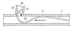
도 3은 혈관 내에 삽입된 의료용 가이드 와이어를 도시하는 단면도이다.
도 4는 혈관 내에 삽입된 의료용 가이드 와이어의 선단부가 반전될 때를 도시하는 단면도이다.
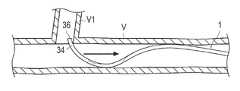
도 5는 혈관 내에 삽입된 의료용 가이드 와이어의 선단부가 기본 형상으로 복귀되었을 때를 도시하는 단면도이다.
도 6은 혈관 내에서 기본 형상으로 복귀된 의료용 가이드 와이어를 나선 형상으로 복귀시킬 때를 도시하는 단면도이다.
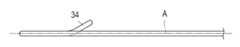
도 7은 본 발명의 실시 형태에 관한 의료용 가이드 와이어의 선단부의 변형예를 도시하는 측면도이다.
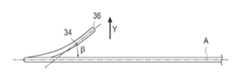
도 8은 본 발명의 실시 형태에 관한 의료용 가이드 와이어의 선단부의 다른 변형예를 도시하는 측면도이다.
도 9는 도 8에 도시하는 의료용 가이드 와이어를 혈관 내에 삽입하였을 때를 도시하는 단면도이다.
도 10은 본 발명의 실시 형태에 관한 의료용 가이드 와이어의 만곡부의 변형예를 선단측으로부터 관찰한 측면도이다.
도 11은 본 발명의 실시 형태에 관한 의료용 가이드 와이어의 만곡부의 다른 변형예를 선단측으로부터 관찰한 측면도이다.
도 12는 본 발명의 실시 형태에 관한 의료용 가이드 와이어의 선단부의 다른 변형예를 도시하는 평면도이다.
도 13은 본 발명의 실시 형태에 관한 의료용 가이드 와이어의 선단부의 또 다른 변형예를 도시하는 평면도이다.Fig. 1 shows a medical guide wire according to an embodiment of the present invention, wherein (A) is a plan view and (B) is a side view.
2 is a side view of the medical guide wire according to the embodiment of the present invention, viewed from the distal end side.
3 is a sectional view showing a medical guide wire inserted into a blood vessel.
4 is a cross-sectional view showing the tip of the medical guidewire inserted into the blood vessel is reversed.
5 is a cross-sectional view showing the distal end portion of the medical guide wire inserted into the blood vessel returned to the basic shape.
6 is a cross-sectional view showing a state in which the medical guide wire returned to the basic shape in the blood vessel is returned to the spiral shape.
7 is a side view showing a modified example of the distal end portion of the medical guide wire according to the embodiment of the present invention.
8 is a side view showing another modified example of the distal end portion of the medical guide wire according to the embodiment of the present invention.
9 is a cross-sectional view showing a state where the medical guide wire shown in Fig. 8 is inserted into a blood vessel.
10 is a side view showing a modified example of a curved portion of the medical guide wire according to the embodiment of the present invention, viewed from the distal end side.
11 is a side view showing another modified example of the curved portion of the medical guide wire according to the embodiment of the present invention, viewed from the distal end side.
12 is a plan view showing another modification of the distal end portion of the medical guide wire according to the embodiment of the present invention.
13 is a plan view showing still another modification of the distal end portion of the medical guide wire according to the embodiment of the present invention.
이하, 도면을 참조하여 본 발명의 실시 형태를 설명한다. 또한, 도면의 치수 비율은, 설명의 편의상, 과장되어 실제의 비율과는 다른 경우가 있다.Hereinafter, embodiments of the present invention will be described with reference to the drawings. In addition, the dimensional ratio in the drawings may be exaggerated and different from the actual ratio for convenience of explanation.
본 발명의 실시 형태에 관한 의료용 가이드 와이어(1)는, 도 1, 도 2에 도시하는 바와 같이, 체강 내로 삽입되는 측의 단부에, 대략 직선 형상의 기단부 영역(2)과, 기단부 영역(2)의 선단측에 위치하는 선단 영역(3)을 갖는다. 또한, 선단 방향은 체강 내에 삽입되는 방향을 나타내고, 기단부 방향은 그 반대 방향을 나타내는 것으로 한다. 선단 영역(3)은, 후술하는 금속으로 이루어지는 심봉이 테이퍼 형상으로 되어 있지만, 반드시 테이퍼 형상이 아니어도 된다.As shown in Figs. 1 and 2, the
가이드 와이어(1)는 금속으로 이루어지는 심봉에 합성 수지층이 피복되어 구성되어 있다. 심봉에 적절하게 사용되는 재료로서는, Ni-Ti 합금과 같은 초탄성 합금이나, 스테인리스 합금 등을 들 수 있고, 1개의 재료로 구성되어도 좋고, 또는 2개 이상의 재료를 접합하여 구성되어도 좋다. 또한 선단에 유연성을 갖게 하기 위해, 선단 부분의 심봉은 테이퍼 형상으로 직경 축소되어 있다. 합성 수지층에 적절하게 사용되는 수지 재료로서는, 폴리우레탄, PTFE(폴리테트라플루오로에틸렌) 등의 불소계 수지, 나일론 등의 폴리아미드계 수지, 폴리에틸렌, 폴리프로필렌 등의 폴리올레핀을 들 수 있다. 이들 수지에는, 산화바륨이나 텅스텐 등의 X선 조영성 미세 분말을 혼입할 수 있다. 또한, 심봉의 선단부에 X선 조영용 백금, 금 등의 코일을 설치함으로써, X선 투시하에서 작업을 행할 수 있는 구성으로 할 수도 있다. 합성 수지층의 표면에는 또한, 무수말레산 등으로 이루어지는 친수성의 윤활성 피막이 코팅되는 것이 바람직하다. 이에 의해, 카테터와 같은 치료용 튜브 내나, 체강 내에서의 삽입 관통 저항이 저감되어, 원활한 삽입이 가능해진다. 윤활성 피막은 체강 내에 삽입되지 않는 부분에는 코팅되지 않는 것이 바람직하다.The
이러한 가이드 와이어(1)의 외경은, 통상 0.1㎜ 내지 1.40㎜ 정도인 것이 바람직하지만, 이것에 한정되지 않는다. 또한, 가이드 와이어(1)의 전체 길이는, 100㎝ 내지 450㎝ 정도, 바람직하게는 120㎝ 내지 350㎝ 정도이지만, 이것에 한정되지 않는다.The outer diameter of the
선단 영역(3)은, 만곡되는 만곡부(32)와, 만곡부(32)에 연속되는 선단부(34)를 갖고, 선단부(34)의 최선단에는 최선단부(36)가 설치되어 있다. 가이드 와이어(1)는, 만곡부(32)가 만곡되어 있음으로써, 기본 형상(전혀 부하가 작용하고 있지 않은 상태에서의 형상)에 있어서, 최선단부(36)가 선단 방향이 아닌 기단부 방향을 향하도록 대략 J자 형상으로 되어 있다.The
만곡부(32)는, 기단부측의 시점부인 만곡 시점(32a)과, 선단측의 종점부인 만곡 종점(32b)과, 만곡 시점(32a)과 만곡 종점(32b)의 중간점인 만곡 중간점(32c)을 갖고 있다. 만곡부(32)는, 만곡 시점(32a)으로부터 만곡 중간점(32c)까지가, 동일 평면인 만곡 평면(A) 상에서 만곡되고, 이 만곡 평면(A) 상에는 기단부 영역(2)도 위치하고 있다. 그리고 만곡부(32)의 만곡 중간점(32c)으로부터 만곡 종점(32b)까지의 부위는, 선단부(34)에 근접함에 따라서, 만곡 평면(A)으로부터 서서히 멀어지도록 연장되어 있다.The
선단부(34)는, 최선단부(36)에 근접함에 따라서 만곡 평면(A)으로부터 서서히 멀어지도록 연장되어, 도 2에 도시하는 만곡 평면(A)과 직교하는 기단부 영역(2)의 축심상의 평면인 직교 평면(B)에 대해, 만곡부(32)가 만곡되어 있는 영역, 즉, 직교 평면(B)을 경계로 만곡부(32)가 연장되어 있는 쪽의 영역에, 최선단부(36)가 위치하도록 형상이 부여되어 있다. 본 실시 형태에서는, 도 1의 (A)에 도시하는 바와 같이, 선단부(34)의 만곡 평면(A)에의 투영선이 기단부 영역(2)과 대략 평행하게 되어 있어, 투영선이 기단부 영역(2)과 교차하지 않는다. 즉, 선단부(34)가, 직교 평면(B)과 교차하지 않는다.The
만곡부(32)의 바람직한 형태로서는, 곡률 반경(R)이 0.2㎜ 내지 20㎜ 정도인 것이 바람직하고, 보다 바람직하게는 0.5㎜ 내지 8㎜이다.As a preferable form of the
또한, 만곡부(32)의 만곡 중간점(32c)으로부터 만곡 종점(32b)까지의 부위 및 선단부(34)의 만곡 평면(A)에 대한 경사각 β는, 대략 일정하게 되어 있지만, 반드시 일정하지 않아도 되고, -90도<경사각 β<90도의 관계를 만족시키는 것이 바람직하다. 또한, 만곡부(32)의 만곡 평면(A)에 대한 경사각과, 선단부(34)의 만곡 평면(A)에 대한 경사각이 달라도 좋다.The inclination angle? Of the
최선단부(36)의 만곡 평면(A)으로부터의 높이 H는, 0㎜<|H|<20㎜의 관계를 만족시키는 것이 바람직하다. 선단부(34)의 만곡 평면(A)에의 투영선의 길이 L은, 0.5㎜ 내지 20㎜인 것이 바람직하다.The height H from the curved plane A of the
또한, 선단부(34)의, 직교 평면(B)에 대한 만곡각 α(도 12 참조)는, 본 실시 형태에서는 0도이지만, 도 12에 도시하는 바와 같이 0도<만곡각 α<90도로 해도 좋고, 또는 도 13에 도시하는 바와 같이, 선단부(34)의 만곡 평면(A)에의 투영선이 기단부 영역(2)과 교차하지 않는 범위에서, 즉 선단부(34)가 직교 평면(B)과 교차하지 않는 범위에서, 만곡각 α<0도로 할 수도 있다.12) of the
다음에, 실시 형태에 관한 의료용 가이드 와이어(1)의 작용에 대해 설명한다.Next, the action of the
시술자가 가이드 와이어(1)의 선단부(34)를 혈관(V) 내에 삽입할 때에는, 인서터라 불리는 관 형상의 기구를 통과시켜 삽입하지만, 기본 형상인 상태에서는 입체 형상을 이루고 있기 때문에 삽입할 수 없으므로, 최선단부(36)가 선단 방향(삽입 방향)을 향하도록 시술자가 선단 영역(3)을 신장한 후 인서터에 삽입한다. 이때, 선단부(34)는 만곡 평면(A)으로부터 이격되도록 연장되어 형상이 부여되어 있으므로, 신장시켰을 때에 만곡부(32)의 주변에 있어서 나선 형상이 형성된다. 이 상태에서 혈관(V) 내에 삽입되면, 도 3에 도시하는 바와 같이, 나선 형상의 일부가 혈관벽과 접촉하므로, 그대로의 형상이 유지된다.When a practitioner inserts the
또한, 시술자가 가이드 와이어(1)의 기단부측을 조작하여 가이드 와이어(1)의 선단을 혈관(V) 내의 안쪽으로 밀어 전진시켜 가면, 최선단부(36)가 분기 혈관(V1)의 입구에 당도해 버리는 경우가 있다. 그러나 본 실시 형태에 관한 가이드 와이어(1)는 선단이 나선 형상으로 되어 있어, 선단부(34)가 나선의 주위 방향으로 권회하면서 가이드 와이어(1)의 진행 방향에 대해 경사진 상태로 되어 있으므로, 최선단부(36)가 분기 혈관(V1)의 입구와 접해도, 나선 피치가 줄어들도록 하여 선단부(34)의 축심이 옆으로 흔들리도록 변형되어, 분기 혈관(V1)의 입구의 접촉점인 혈관벽에 가해지는 저항력을 분산시킬 수 있다. 이에 의해, 가이드 와이어(1)의 분기 혈관(V1)에의 오진입을 감소시킬 수 있고, 또한 환자에 대해 조영제를 사용한 확인 작업도 감소시킬 수 있으므로, 환자의 신체에의 부담이 적어지고, 또한 조영제 비용도 삭감할 수 있다.When the operator manipulates the proximal end side of the
또한, 본 실시 형태에서는, 만곡부(32)의 도중인 만곡 중간점(32c)으로부터 선단측이, 기본 형상에 있어서 만곡 평면(A)으로부터 서서히 멀어지도록 연장되어 있으므로, 나선 형상의 복원력을 높일 수 있고, 신장되어 나선 형상으로 되기 쉬워, 선단 영역(3)에 가해지는 저항력을 분산시키는 효과를 더욱 높일 수 있다.Further, in this embodiment, since the distal end side from the curved
또한, 도 4에 도시하는 바와 같이, 최선단부(36)가 분기 혈관(V1)의 입구에 당도하여, 시술자가 더욱 밀어 넣으면 혈관벽과 선단부(34)의 접촉이 계기가 되어, 가이드 와이어(1)의 선단부(34)가 반전되어 최선단부(36)가 기단부 방향을 향해, 도 5에 도시하는 바와 같이, 혈관 삽입 전의 기본 형상으로 복귀하는 것이 가능해진다. 이에 의해, 가이드 와이어(1)의 만곡부(32)가 삽입 방향 최선단으로 되어, 시술자의 강인한 압입에 대해서도, 최선단부(36)가 혈관벽에 접촉되기 어려워, 혈관벽의 손상을 억제할 수 있는 안전성이 높아진 형상으로 된다. 또한, 삽입 방향 최선단으로 되는 만곡부(32)의 만곡 중간점(32c)이, 혈관 직경의 중앙에 위치하도록 구성되어 있으므로, 만곡 중간점(32c)이 혈관벽과 접촉되기 어려워져, 혈관(V) 내에 있어서 가이드 와이어(1)를 원활하게 직진시키는 것이 가능해진다. 이와 같이, 본 발명의 가이드 와이어는, 혈관(V) 내에 삽입된 형상(신장된 형상)일 때에는 분기 혈관에의 오진입 방지성 및 조작성이 향상되고, 선단 영역(3)이 반전된 형상일 때에는, 조작성을 유지한 상태에서 안전성이 더욱 향상된다. 즉, 본 발명의 가이드 와이어는, 분기 혈관에의 오진입 방지성, 조작성 및 안전성을 밸런스 좋게 실현할 수 있다.4, the
또한, 가이드 와이어(1)의 선단 영역(3)이 반전되어 최선단부(36)가 기단부 방향을 향한 후, 가이드 와이어(1)를 다시 신장된 형상으로 하고자 하는 경우에는, 도 6에 도시하는 바와 같이, 분기 혈관(V1)의 입구에 가이드 와이어(1)의 최선단부(36)를 걸리게 한 후, 가이드 와이어(1)를 후방으로 되돌림으로써, 다시 나선 형상으로 할 수 있고, 이 후, 최선단부(36)가 분기 혈관(V1)의 입구에 걸리지 않도록 조작하면서, 나선 형상을 유지하면서 가이드 와이어(1)를 밀어 전진시킬 수 있다. 이때, 최선단부(36)를 포함하는 선단부(34)가, 직교 평면(B)에 대해 만곡부(32)가 만곡되는 영역에 위치하고 있으므로, 가이드 와이어(1)를 후방으로 되돌림으로써 용이하게 나선 형상으로 복귀시킬 수 있다. 즉, 최선단부(36)가 직교 평면(B)에 대해 만곡부(32)의 만곡되는 영역과 반대측에 위치하는 경우, 선단부(34)의 만곡 평면(A)에의 투영선이 기단부 영역(2)과 교차하므로, 최선단부(36)를 걸리게 하여 가이드 와이어(1)를 후방으로 되돌리면, 선단부(34)와 기단부 영역(2)과 교차가 강해지기 쉬워, 즉 만곡부(32)의 곡률 반경(R)이 작아지도록 변형되기 쉬워져 나선 형상으로 복귀되기 어려워지지만, 본 실시 형태에서는, 최선단부(36)가 직교 평면(B)에 대해 만곡부(32)의 만곡되는 영역에 위치하고, 선단부(34)가 직교 평면(B)과 교차하고 있지 않으므로, 가이드 와이어(1)가 용이하게 나선 형상으로 복귀되기 쉽다.When the
또한, 본 발명은 상술한 실시 형태에 한정되는 것은 아니며, 특허청구범위 내에서 다양하게 개변할 수 있다.The present invention is not limited to the above-described embodiments, but can be variously modified within the scope of the claims.
예를 들어, 선단부(34)의 형태는, 도 1, 도 2에 도시하는 형태에 한정되지 않는다. 따라서, 예를 들어 도 7에 도시하는 바와 같이, 선단부(34)의 선단측의 일부만이, 만곡 평면(A)으로부터 서서히 멀어지도록 연장해도 좋다.For example, the shape of the
또한, 도 8에 도시하는 바와 같이, 만곡 평면(A)에 대한 선단부(34)의 경사각 β가, 최선단부(36)에 근접함에 따라서 커지도록 하여, Y 방향으로 만곡된 형상으로 할 수도 있다. 이러한 형태로 함으로써, 도 9에 도시하는 바와 같이, 혈관(V) 내에 삽입하였을 때에, 선단부(34)의 최선단부(36)와는 다른 부위를 혈관벽과 접촉시켜, 최선단부(36)가 혈관벽과 접촉하지 않도록 하는 것이 가능해져, 가이드 와이어(1)의 최선단부(36)의 혈관(V)에 대한 긁힘이나 충돌을 저감시켜 안전성을 높일 수 있다. 또한, 만곡 평면(A)에 대한 선단부(34)의 경사각 β가, 최선단부(36)에 근접함에 따라서 서서히 커지는 것이 아니라, 국소적으로 굴곡되어 커져도 좋다.8, the inclination angle? Of the
또한, 선단부(34)의 Y 방향으로의 만곡의 정도는, 가이드 와이어(1)에 따라 적절하게 변경하는 것이 바람직하다. 일례로서, 분지 혈관이 많은 쇄골하동맥에 있어서 효과를 발휘시키기 위해서는, 평균적인 쇄골하동맥의 내경이 6㎜ 정도이므로, 내경 6㎜의 관 내에서 가이드 와이어(1)가 나선 형상으로 되었을 때에, 최선단부(36)가 관의 내벽에 접촉하지 않고, 내경의 대략 중심에 위치하도록 설정하는 것이 바람직하다. 최선단부(36)가 혈관벽과 접촉하지 않고, 또한 내경의 대략 중심에 위치시킴으로써, 가이드 와이어(1)의 분기 혈관(V1)에의 오삽입을 보다 확실하게 억제할 수 있어, 원활하고 또한 안전하게 가이드 와이어(1)를 추진할 수 있다.The degree of curvature of the
또한, 만곡부(32)의 형태는, 만곡부(32)의 적어도 기단부측의 일부가 만곡 평면(A) 상에 위치하면, 도 1, 도 2에 도시한 형태에 한정되지 않는다. 따라서, 예를 들어 도 10에 도시하는 바와 같이, 만곡부(32) 전체가, 만곡 평면(A) 상에 위치해도 된다.The shape of the
또한, 도 11에 도시하는 바와 같이, 만곡 시점(32a)으로부터 만곡 종점(32b)까지의 만곡 평면(A)에 대한 경사각 β가 선단부(34)에 근접함에 따라서 커지도록 하고, 만곡 평면(A)으로부터 이격되는 Y 방향으로 만곡된 형상으로 해도 좋다. 이 경우에는, 만곡 시점(32a)에 있어서의 접선이 만곡 평면(A)에 위치하게 된다. 또한, Y 방향으로 만곡되는 부위가, 만곡부(32)의 전체가 아닌 일부라도 좋고, 또한 Y 방향으로 국소적으로 굴곡되어도 좋다.11, the inclination angle? From the
또한, 전술하였지만, 도 12에 도시하는 바와 같이, 선단부(34)의 최선단부(36)가, 직교 평면(B)과 평행하고 만곡 종점(32b)이 위치하는 평면(C)보다도, 직교 평면(B)으로부터 이격되는 측에 위치해도 좋다. 또한, 도 13에 도시한 바와 같이, 선단부(34)의 최선단부(36)가, 직교 평면(B)과 평행하고 만곡 종점(32b)이 위치하는 평면(C)보다도, 직교 평면(B)에 근접하는 측에 위치해도 좋다.12, the
또한, 선단 영역(3)은 코일 등의 금속 소선을 권취함으로써, 적절하게 강성을 향상시키는 구성이라도 좋고, 금속 코어선을 프레스한 평판 형상으로 하는 구성이라도 좋다. 또한 목적에 따라서, 코일 등의 금속 소선을 권취하는 위치나, 금속 코어선을 프레스하여 평판 형상으로 하는 위치는, 적절하게 변경할 수 있다.The
또한, 본 발명에 관한 가이드 와이어는, 레이디얼이나 브라키알 및 페모랄로부터, 가이드 와이어나 카테터 등의 의료 기구를, 흉부나 복부 등의 목적으로 하는 부위까지 도입하기 위해 사용하는 것이 가능하고, 천자 부위나 목적 부위에 따라 적용 범위가 한정되는 것은 아니다.The guide wire according to the present invention can be used for introducing a medical instrument such as a guide wire or a catheter from a radial, a brachyury and a pemoral to a target site such as a chest or abdomen, The scope of application is not limited depending on the site or the target site.
또한, 본 출원은, 2009년 4월 14일에 출원된 일본 특허 출원 번호 제2009-098463호에 기초하고 있고, 그들의 개시 내용은 참조되어, 전체로서 포함되어 있다.The present application is based on Japanese Patent Application No. 2009-098463 filed on April 14, 2009, the disclosure of which is incorporated herein by reference in its entirety.
1 : 의료용 가이드 와이어
2 : 기단부 영역
3 : 선단 영역
32 : 만곡부
32a : 만곡 시점
32b : 만곡 종점
32c : 만곡 중간점
34 : 선단부
36 : 최선단부
A : 만곡 평면
B : 직교 평면1: Medical guide wire
2: proximal region
3: leading edge area
32:
32a: Curved point
32b: Curvilinear end point
32c: Curved midpoint
34:
36: Best End
A: Curved plane
B: Orthogonal plane
Claims (4)
Translated fromKorean상기 선단 영역은, 상기 기단부 영역에 연속되는 만곡부와, 상기 만곡부의 선단측에 연속되는 선단부를 갖고,
상기 기단부 영역 및 당해 기단부 영역에 연속되는 상기 만곡부의 기단부측의 시점과 선단측의 종점의 중간점으로부터 기단부측이 동일한 만곡 평면 상에 위치하고,
상기 만곡부는, 상기 중간점으로부터 선단측이 상기 만곡 평면으로부터 멀어지는 방향으로 연장되어 있고,
상기 선단부는, 상기 만곡 평면으로부터 멀어지는 방향으로 연장되어, 상기 만곡 평면과 직교하는 상기 기단부 영역의 축심상의 직교 평면에 대해, 상기 만곡부가 만곡되는 방향의 영역에 최선단부를 갖는, 의료용 가이드 와이어.A medical guidewire having a linear base end region and a distal end region continuous to the distal end side of the base end region and having a best end portion oriented in the base end direction in a basic shape in which no load is applied,
Wherein the leading end region has a curved portion continuous to the base end region and a leading end continuous to the leading end side of the curved portion,
The proximal end side of the curved portion continuing to the proximal end region and the proximal end portion region is located on the same curved plane from the midpoint between the starting point on the proximal end side and the distal end side end point,
Wherein the curved portion extends from the intermediate point in a direction away from the curved plane,
Wherein the distal end portion extends in a direction away from the curved plane and has a best end in a region in a direction in which the curved portion is bent with respect to an axial orthogonal plane of the proximal end portion region orthogonal to the curved plane.
Applications Claiming Priority (2)
| Application Number | Priority Date | Filing Date | Title |
|---|---|---|---|
| JPJP-P-2009-098463 | 2009-04-14 | ||
| JP2009098463 | 2009-04-14 |
Publications (2)
| Publication Number | Publication Date |
|---|---|
| KR20120027116A KR20120027116A (en) | 2012-03-21 |
| KR101632457B1true KR101632457B1 (en) | 2016-06-21 |
Family
ID=42982529
Family Applications (1)
| Application Number | Title | Priority Date | Filing Date |
|---|---|---|---|
| KR1020117021362AActiveKR101632457B1 (en) | 2009-04-14 | 2010-04-13 | Medical guide wire |
Country Status (6)
| Country | Link |
|---|---|
| US (1) | US8517959B2 (en) |
| EP (1) | EP2420282B1 (en) |
| JP (1) | JP5639580B2 (en) |
| KR (1) | KR101632457B1 (en) |
| CN (1) | CN102395400B (en) |
| WO (1) | WO2010119867A1 (en) |
Families Citing this family (51)
| Publication number | Priority date | Publication date | Assignee | Title |
|---|---|---|---|---|
| EP1907042B1 (en) | 2005-07-06 | 2009-03-11 | Vascular Pathways Inc. | Intravenous catheter insertion device and method of use |
| EP2150304B1 (en) | 2007-05-07 | 2010-12-01 | Vascular Pathways Inc. | Intravenous catheter insertion and blood sample devices and method of use |
| US10363389B2 (en) | 2009-04-03 | 2019-07-30 | Scientia Vascular, Llc | Micro-fabricated guidewire devices having varying diameters |
| US11406791B2 (en) | 2009-04-03 | 2022-08-09 | Scientia Vascular, Inc. | Micro-fabricated guidewire devices having varying diameters |
| WO2010077692A2 (en) | 2008-12-08 | 2010-07-08 | Scientia Vascular Llc | Micro-cutting machine for forming cuts in products |
| US12220538B2 (en) | 2008-12-08 | 2025-02-11 | Scientia Vascular, Inc. | Micro-fabricated intravascular devices having varying diameters |
| US9950137B2 (en) | 2009-04-03 | 2018-04-24 | Scientia Vascular, Llc | Micro-fabricated guidewire devices formed with hybrid materials |
| US10384039B2 (en) | 2010-05-14 | 2019-08-20 | C. R. Bard, Inc. | Catheter insertion device including top-mounted advancement components |
| US11925779B2 (en) | 2010-05-14 | 2024-03-12 | C. R. Bard, Inc. | Catheter insertion device including top-mounted advancement components |
| US8932258B2 (en) | 2010-05-14 | 2015-01-13 | C. R. Bard, Inc. | Catheter placement device and method |
| US9950139B2 (en) | 2010-05-14 | 2018-04-24 | C. R. Bard, Inc. | Catheter placement device including guidewire and catheter control elements |
| US9872971B2 (en) | 2010-05-14 | 2018-01-23 | C. R. Bard, Inc. | Guidewire extension system for a catheter placement device |
| US8690833B2 (en) | 2011-01-31 | 2014-04-08 | Vascular Pathways, Inc. | Intravenous catheter and insertion device with reduced blood spatter |
| ES2835652T3 (en) | 2011-02-25 | 2021-06-22 | Bard Inc C R | Medical component insertion device including a retractable needle |
| USD903101S1 (en) | 2011-05-13 | 2020-11-24 | C. R. Bard, Inc. | Catheter |
| US10213187B1 (en) | 2012-01-25 | 2019-02-26 | Mubin I. Syed | Method and apparatus for percutaneous superficial temporal artery access for carotid artery stenting |
| US20150201900A1 (en)* | 2012-01-25 | 2015-07-23 | Mubin I. Syed | Multi-pane imaging transducer associated with a guidewire |
| JP2014018574A (en)* | 2012-07-23 | 2014-02-03 | Piolax Medical Device:Kk | Guide wire |
| WO2014081947A1 (en) | 2012-11-21 | 2014-05-30 | Syed Mubin I | System for the intravascular placement of a medical device |
| WO2014120741A1 (en) | 2013-01-30 | 2014-08-07 | Vascular Pathways, Inc. | Systems and methods for venipuncture and catheter placement |
| WO2014197962A1 (en)* | 2013-06-12 | 2014-12-18 | Carnevale Francisco Cesar | Catheter and methods related thereto |
| WO2016037127A1 (en) | 2014-09-05 | 2016-03-10 | C.R. Bard, Inc. | Catheter insertion device including retractable needle |
| US9636244B2 (en) | 2015-04-09 | 2017-05-02 | Mubin I. Syed | Apparatus and method for proximal to distal stent deployment |
| USD903100S1 (en) | 2015-05-01 | 2020-11-24 | C. R. Bard, Inc. | Catheter placement device |
| CN113350614A (en) | 2015-05-15 | 2021-09-07 | C·R·巴德股份有限公司 | Catheter placement device including extendable needle safety feature |
| US10779976B2 (en) | 2015-10-30 | 2020-09-22 | Ram Medical Innovations, Llc | Apparatus and method for stabilization of procedural catheter in tortuous vessels |
| US10327929B2 (en) | 2015-10-30 | 2019-06-25 | Ram Medical Innovations, Llc | Apparatus and method for stabilization of procedural catheter in tortuous vessels |
| US11020256B2 (en) | 2015-10-30 | 2021-06-01 | Ram Medical Innovations, Inc. | Bifurcated “Y” anchor support for coronary interventions |
| US10492936B2 (en) | 2015-10-30 | 2019-12-03 | Ram Medical Innovations, Llc | Apparatus and method for improved access of procedural catheter in tortuous vessels |
| US10173031B2 (en) | 2016-06-20 | 2019-01-08 | Mubin I. Syed | Interchangeable flush/selective catheter |
| US11207502B2 (en) | 2016-07-18 | 2021-12-28 | Scientia Vascular, Llc | Guidewire devices having shapeable tips and bypass cuts |
| US11052228B2 (en) | 2016-07-18 | 2021-07-06 | Scientia Vascular, Llc | Guidewire devices having shapeable tips and bypass cuts |
| US10646689B2 (en) | 2016-07-29 | 2020-05-12 | Cephea Valve Technologies, Inc. | Mechanical interlock for catheters |
| US10493262B2 (en) | 2016-09-12 | 2019-12-03 | C. R. Bard, Inc. | Blood control for a catheter insertion device |
| US10821268B2 (en) | 2016-09-14 | 2020-11-03 | Scientia Vascular, Llc | Integrated coil vascular devices |
| US11452541B2 (en) | 2016-12-22 | 2022-09-27 | Scientia Vascular, Inc. | Intravascular device having a selectively deflectable tip |
| EP3585471B1 (en) | 2017-03-01 | 2025-01-01 | C. R. Bard, Inc. | Catheter insertion device |
| ES2966345T3 (en) | 2017-05-26 | 2024-04-22 | Scientia Vascular Inc | Microfabricated medical device with a non-helical cutting arrangement |
| US11007075B2 (en) | 2018-02-18 | 2021-05-18 | Ram Medical Innovations, Inc. | Vascular access devices and methods for lower limb interventions |
| US11305095B2 (en) | 2018-02-22 | 2022-04-19 | Scientia Vascular, Llc | Microfabricated catheter having an intermediate preferred bending section |
| ES2980192T3 (en) | 2018-03-07 | 2024-09-30 | Bard Access Systems Inc | Guidewire advancement and blood reflux systems for a medical device insertion system |
| US10667833B2 (en)* | 2018-06-08 | 2020-06-02 | Neuravi Limited | Guidewire with an atraumatic clot-circumventing configured distal end for use in an endovascular medical system |
| USD921884S1 (en) | 2018-07-27 | 2021-06-08 | Bard Access Systems, Inc. | Catheter insertion device |
| US12011555B2 (en) | 2019-01-15 | 2024-06-18 | Scientia Vascular, Inc. | Guidewire with core centering mechanism |
| CA3151126A1 (en) | 2019-08-19 | 2021-02-25 | Becton, Dickinson And Company | Midline catheter placement device |
| US12178975B2 (en) | 2020-01-23 | 2024-12-31 | Scientia Vascular, Inc. | Guidewire having enlarged, micro-fabricated distal section |
| US12343485B2 (en) | 2020-01-23 | 2025-07-01 | Scientia Vascular, Inc. | High torque guidewire device |
| US20230042352A1 (en)* | 2020-01-29 | 2023-02-09 | Baylis Medical Company Inc. | Medical guidewire assembly having predetermined spatial geometry |
| WO2022024201A1 (en)* | 2020-07-27 | 2022-02-03 | 朝日インテック株式会社 | Catheter |
| US12296112B2 (en) | 2020-10-05 | 2025-05-13 | Scientia Vascular, Inc. | Microfabricated catheter devices with high axial strength |
| US12178974B2 (en) | 2021-01-21 | 2024-12-31 | Abbott Cardiovascular Systems Inc. | Guidewire and method of use |
Citations (3)
| Publication number | Priority date | Publication date | Assignee | Title |
|---|---|---|---|---|
| JP2004181184A (en) | 2002-12-03 | 2004-07-02 | Teruo Hashimoto | Medical guide wire |
| JP2006141778A (en) | 2004-11-22 | 2006-06-08 | Tonokura Ika Kogyo Kk | Guide catheter set body for balloon catheter |
| JP2006230482A (en) | 2005-02-22 | 2006-09-07 | Kaneka Corp | Blood removing catheter |
Family Cites Families (30)
| Publication number | Priority date | Publication date | Assignee | Title |
|---|---|---|---|---|
| US4898591A (en)* | 1988-08-09 | 1990-02-06 | Mallinckrodt, Inc. | Nylon-PEBA copolymer catheter |
| US4950228A (en)* | 1990-01-10 | 1990-08-21 | Knapp Jr Peter M | Ureteral stent |
| US5445625A (en)* | 1991-01-23 | 1995-08-29 | Voda; Jan | Angioplasty guide catheter |
| US5295493A (en)* | 1992-03-19 | 1994-03-22 | Interventional Technologies, Inc. | Anatomical guide wire |
| US5306263A (en)* | 1992-05-01 | 1994-04-26 | Jan Voda | Catheter |
| US5427119A (en)* | 1993-11-03 | 1995-06-27 | Daig Corporation | Guiding introducer for right atrium |
| US5575766A (en)* | 1993-11-03 | 1996-11-19 | Daig Corporation | Process for the nonsurgical mapping and treatment of atrial arrhythmia using catheters guided by shaped guiding introducers |
| US6203531B1 (en)* | 1993-11-03 | 2001-03-20 | Daig Corporation | Guiding introducers for use in the treatment of accessory pathways around the mitral valve using a retrograde approach |
| US5722400A (en)* | 1995-02-16 | 1998-03-03 | Daig Corporation | Guiding introducers for use in the treatment of left ventricular tachycardia |
| JP3300155B2 (en) | 1994-03-23 | 2002-07-08 | 株式会社パイオラックス | How to shape the tip of a medical guidewire |
| US5814029A (en)* | 1994-11-03 | 1998-09-29 | Daig Corporation | Guiding introducer system for use in ablation and mapping procedures in the left ventricle |
| SE9601541D0 (en) | 1995-11-08 | 1996-04-23 | Pacesetter Ab | Guidewire assembly |
| SE9504334D0 (en) | 1995-12-04 | 1995-12-04 | Pacesetter Ab | Guidewire assembly |
| JP4198214B2 (en) | 1997-09-10 | 2008-12-17 | テルモ株式会社 | Guide wire |
| JP2002511292A (en) | 1998-04-13 | 2002-04-16 | プロリフィックス メディカル, インコーポレイテッド | Guidewire for accurate catheter positioning |
| EP1105181B1 (en) | 1998-08-19 | 2004-02-04 | Cook Incorporated | Preformed wire guide |
| AUPP907599A0 (en) | 1999-03-08 | 1999-04-01 | Baxter International Inc. | Directional guidewire |
| US6214016B1 (en) | 1999-04-29 | 2001-04-10 | Medtronic, Inc. | Medical instrument positioning device internal to a catheter or lead and method of use |
| DE69926889T2 (en) | 1999-09-09 | 2006-06-14 | Schneider Europ Gmbh Buelach | Guide to medical devices |
| US7674245B2 (en)* | 2001-06-07 | 2010-03-09 | Cardiac Pacemakers, Inc. | Method and apparatus for an adjustable shape guide catheter |
| DE10217757A1 (en)* | 2002-04-20 | 2003-10-30 | Friedhelm Brassel | Medical retriever |
| JP4188663B2 (en) | 2002-11-06 | 2008-11-26 | 株式会社パイオラックスメディカルデバイス | Guide wire |
| JP4197961B2 (en)* | 2003-01-22 | 2008-12-17 | 朝日インテック株式会社 | Manufacturing method of medical guide wire |
| JP2006025907A (en) | 2004-07-13 | 2006-02-02 | Kawasumi Lab Inc | Guide wire |
| JP4907945B2 (en) | 2004-11-01 | 2012-04-04 | テルモ株式会社 | Medical guidewire |
| EP1852138A4 (en)* | 2005-02-22 | 2013-12-04 | Kaneka Corp | Catheter |
| JP4680007B2 (en) | 2005-08-29 | 2011-05-11 | 日本ライフライン株式会社 | Stylet |
| JP5028406B2 (en) | 2006-03-06 | 2012-09-19 | テルモ株式会社 | Guide wire |
| JP5030546B2 (en)* | 2006-11-17 | 2012-09-19 | メディキット株式会社 | Medical guidewire |
| JP2009098463A (en) | 2007-10-17 | 2009-05-07 | Canon Inc | Image forming apparatus |
- 2010
- 2010-04-13KRKR1020117021362Apatent/KR101632457B1/enactiveActive
- 2010-04-13WOPCT/JP2010/056600patent/WO2010119867A1/enactiveApplication Filing
- 2010-04-13JPJP2011509299Apatent/JP5639580B2/enactiveActive
- 2010-04-13EPEP10764451.0Apatent/EP2420282B1/enactiveActive
- 2010-04-13CNCN201080016967.9Apatent/CN102395400B/enactiveActive
- 2011
- 2011-10-11USUS13/270,601patent/US8517959B2/ennot_activeExpired - Fee Related
Patent Citations (3)
| Publication number | Priority date | Publication date | Assignee | Title |
|---|---|---|---|---|
| JP2004181184A (en) | 2002-12-03 | 2004-07-02 | Teruo Hashimoto | Medical guide wire |
| JP2006141778A (en) | 2004-11-22 | 2006-06-08 | Tonokura Ika Kogyo Kk | Guide catheter set body for balloon catheter |
| JP2006230482A (en) | 2005-02-22 | 2006-09-07 | Kaneka Corp | Blood removing catheter |
Also Published As
| Publication number | Publication date |
|---|---|
| CN102395400A (en) | 2012-03-28 |
| CN102395400B (en) | 2014-12-03 |
| WO2010119867A1 (en) | 2010-10-21 |
| KR20120027116A (en) | 2012-03-21 |
| EP2420282A4 (en) | 2012-10-03 |
| JP5639580B2 (en) | 2014-12-10 |
| US8517959B2 (en) | 2013-08-27 |
| JPWO2010119867A1 (en) | 2012-10-22 |
| EP2420282A1 (en) | 2012-02-22 |
| EP2420282B1 (en) | 2019-09-18 |
| US20120029478A1 (en) | 2012-02-02 |
Similar Documents
| Publication | Publication Date | Title |
|---|---|---|
| KR101632457B1 (en) | Medical guide wire | |
| JP5512716B2 (en) | Guide wire | |
| EP2949358A1 (en) | Catheter | |
| US20160001048A1 (en) | Guidewire | |
| US20100087780A1 (en) | Wire Guide having Variable Flexibility and Method of Use Thereof | |
| JP2010029559A (en) | Catheter assembly | |
| EP4249030A1 (en) | Medical catheter and preparation method therefor | |
| US9492642B2 (en) | Guidewire | |
| JP2013039305A (en) | Guidewire | |
| US20120065621A1 (en) | Double lumen tubing with improved kinking resistance | |
| US20230173226A1 (en) | Catheter and method for engaging catheter | |
| WO2022158418A1 (en) | Catheter | |
| US20080319419A1 (en) | Medical catheter and a catheter assemble | |
| JP3179894U (en) | catheter | |
| JP6754270B2 (en) | Catheter assembly | |
| US9808604B2 (en) | Guide wire | |
| JP4316252B2 (en) | catheter | |
| JP7738429B2 (en) | catheter | |
| JP6754271B2 (en) | Catheter assembly | |
| WO2018074074A1 (en) | Catheter assembly | |
| JP2024012725A (en) | catheter | |
| JP2024036701A (en) | catheter | |
| JP2024040728A (en) | catheter | |
| JP2024032024A (en) | Catheter and catheter assembly | |
| WO2024121990A1 (en) | Catheter |
Legal Events
| Date | Code | Title | Description |
|---|---|---|---|
| PA0105 | International application | Patent event date:20110914 Patent event code:PA01051R01D Comment text:International Patent Application | |
| PG1501 | Laying open of application | ||
| A201 | Request for examination | ||
| PA0201 | Request for examination | Patent event code:PA02012R01D Patent event date:20141028 Comment text:Request for Examination of Application | |
| E902 | Notification of reason for refusal | ||
| PE0902 | Notice of grounds for rejection | Comment text:Notification of reason for refusal Patent event date:20151130 Patent event code:PE09021S01D | |
| E701 | Decision to grant or registration of patent right | ||
| PE0701 | Decision of registration | Patent event code:PE07011S01D Comment text:Decision to Grant Registration Patent event date:20160523 | |
| GRNT | Written decision to grant | ||
| PR0701 | Registration of establishment | Comment text:Registration of Establishment Patent event date:20160615 Patent event code:PR07011E01D | |
| PR1002 | Payment of registration fee | Payment date:20160615 End annual number:3 Start annual number:1 | |
| PG1601 | Publication of registration | ||
| FPAY | Annual fee payment | Payment date:20190530 Year of fee payment:4 | |
| PR1001 | Payment of annual fee | Payment date:20190530 Start annual number:4 End annual number:4 | |
| PR1001 | Payment of annual fee | Payment date:20210601 Start annual number:6 End annual number:6 | |
| PR1001 | Payment of annual fee | Payment date:20240520 Start annual number:9 End annual number:9 |