KR101629708B1 - Manufacturing method of artificial intervertebral disc and artificial intervertebral disc thereby - Google Patents
Manufacturing method of artificial intervertebral disc and artificial intervertebral disc therebyDownload PDFInfo
- Publication number
- KR101629708B1 KR101629708B1KR1020140156969AKR20140156969AKR101629708B1KR 101629708 B1KR101629708 B1KR 101629708B1KR 1020140156969 AKR1020140156969 AKR 1020140156969AKR 20140156969 AKR20140156969 AKR 20140156969AKR 101629708 B1KR101629708 B1KR 101629708B1
- Authority
- KR
- South Korea
- Prior art keywords
- plate member
- upper plate
- lower plate
- intermediate body
- artificial disc
- Prior art date
- Legal status (The legal status is an assumption and is not a legal conclusion. Google has not performed a legal analysis and makes no representation as to the accuracy of the status listed.)
- Active
Links
Images


Classifications
- A—HUMAN NECESSITIES
- A61—MEDICAL OR VETERINARY SCIENCE; HYGIENE
- A61F—FILTERS IMPLANTABLE INTO BLOOD VESSELS; PROSTHESES; DEVICES PROVIDING PATENCY TO, OR PREVENTING COLLAPSING OF, TUBULAR STRUCTURES OF THE BODY, e.g. STENTS; ORTHOPAEDIC, NURSING OR CONTRACEPTIVE DEVICES; FOMENTATION; TREATMENT OR PROTECTION OF EYES OR EARS; BANDAGES, DRESSINGS OR ABSORBENT PADS; FIRST-AID KITS
- A61F2/00—Filters implantable into blood vessels; Prostheses, i.e. artificial substitutes or replacements for parts of the body; Appliances for connecting them with the body; Devices providing patency to, or preventing collapsing of, tubular structures of the body, e.g. stents
- A61F2/02—Prostheses implantable into the body
- A61F2/30—Joints
- A61F2/44—Joints for the spine, e.g. vertebrae, spinal discs
- A—HUMAN NECESSITIES
- A61—MEDICAL OR VETERINARY SCIENCE; HYGIENE
- A61F—FILTERS IMPLANTABLE INTO BLOOD VESSELS; PROSTHESES; DEVICES PROVIDING PATENCY TO, OR PREVENTING COLLAPSING OF, TUBULAR STRUCTURES OF THE BODY, e.g. STENTS; ORTHOPAEDIC, NURSING OR CONTRACEPTIVE DEVICES; FOMENTATION; TREATMENT OR PROTECTION OF EYES OR EARS; BANDAGES, DRESSINGS OR ABSORBENT PADS; FIRST-AID KITS
- A61F2/00—Filters implantable into blood vessels; Prostheses, i.e. artificial substitutes or replacements for parts of the body; Appliances for connecting them with the body; Devices providing patency to, or preventing collapsing of, tubular structures of the body, e.g. stents
- A61F2/02—Prostheses implantable into the body
- A61F2/30—Joints
- A61F2002/30001—Additional features of subject-matter classified in A61F2/28, A61F2/30 and subgroups thereof
Landscapes
- Health & Medical Sciences (AREA)
- Orthopedic Medicine & Surgery (AREA)
- Engineering & Computer Science (AREA)
- Biomedical Technology (AREA)
- Heart & Thoracic Surgery (AREA)
- Cardiology (AREA)
- Oral & Maxillofacial Surgery (AREA)
- Transplantation (AREA)
- Neurology (AREA)
- Vascular Medicine (AREA)
- Life Sciences & Earth Sciences (AREA)
- Animal Behavior & Ethology (AREA)
- General Health & Medical Sciences (AREA)
- Public Health (AREA)
- Veterinary Medicine (AREA)
- Prostheses (AREA)
Abstract
Translated fromKoreanDescription
Translated fromKorean본 발명은 인공 디스크의 제조방법 및 이에 의해 제조된 인공 디스크에 관한 것으로서, 중간체의 결합면에 접촉하는 상판과 하판을 중간체와 동일한 재질로 형성하여 인공 디스크의 내구성을 향상시키고, 인공 디스크에 대한 구조를 개선하여 인체의 움직임이나, 외부 충격 등에 의해서도 충격을 완화시키는 인공 디스크의 제조방법 및 이에 의해 제조된 인공 디스크에 관한 것이다.The present invention relates to a method of manufacturing an artificial disc and an artificial disc manufactured by the method, wherein an upper plate and a lower plate contacting the coupling surface of the intermediate body are formed of the same material as the intermediate body to improve the durability of the artificial disc, To an artificial disc manufacturing method for mitigating an impact even by a movement of a human body or an external impact, and an artificial disc manufactured thereby.
일반적으로 척추는 인체의 뒤쪽에서 보면 곧은 일자 형태이나, 옆에서 보면 S자 형태로 형성되며, 척추뼈 사이에는 인체가 움직이거나 각 기관의 관절이 작동할때마다 그에 따른 충격을 흡수하고, 하중을 지지하기 위한 디스크가 위치하고 있다.In general, the vertebrae are formed in the shape of a straight line when viewed from the back of the human body, but they are formed in an S shape when seen from the side. The human body moves between the vertebrae or absorbs the impacts when each joint of the organs operates, A disc for supporting is located.
상기 디스크의 구조는 안쪽에는 젤 형태의 수핵이 있으며, 그 바깥쪽은 인대 및 근육질과 같은 섬유질 밴드에 의해 보호되고 있으며, 척추가 움직일 때마다 수핵의 위치와 모양이 바뀌면서 완충 작용을 하여 척추에 가해지는 충격을 최소화하게 된다.The structure of the disk is gel-like nucleus inside, and the outside is protected by fibrous bands such as ligament and muscle. When the spine moves, the position and shape of the nucleus are changed and buffering action is applied to the spine. Thereby minimizing the impact of the impact.
그러나, 노화가 진행됨에 따라 수핵의 양이 줄어들게 되면 탄력이 줄어들게 되고, 외부 충격 등에 의해 디스크의 손상이나 이탈이 발생하게 되면, 디스크는 그 완충 기능을 상실하게 되어 섬유질에 과도한 압력이 가해지면서 허리 통증이나 더욱 심하게 되면 골반, 다리 등에 통증이 발생하게 된다.However, when the amount of nucleus pulposus is reduced as the aging progresses, the elasticity is reduced. When the disk is damaged or detached due to an external impact, the disk loses its buffering function and excessive pressure is applied to the fiber, Or more severe pain, such as pelvis and legs will occur.
이러한 디스크에 이상이 발생하는 경우, 비수술적 치료와 수술적 치료에 의해 디스크의 기능을 회복하고자 하는 방법이 있으나, 본 발명에서는 수술적 치료 방법 중의 하나로 손상된 디스크를 제거하고 척추뼈 사이에 인공 디스크를 삽입하는 것에 대해서 살펴보고자 한다.In the present invention, one of the surgical treatment methods is to remove the damaged disk and to remove the artificial disc between the vertebrae bones by using the non-surgical treatment and the surgical treatment. Let's take a look at the insertion.
종래의 인공 디스크는 일반적으로 상판과 하판, 그리고 상기 상판과 하판 사이에 삽입하는 중간체로 구성된다.Conventional artificial discs generally consist of an upper plate, a lower plate, and an intermediate member inserted between the upper plate and the lower plate.
상기 상판과 하판은 인접하는 척추뼈들 사이에 각각 삽입되고, 상판과 하판 사이에 중간체가 삽입되게 된다.The upper plate and the lower plate are respectively inserted between adjacent vertebrae, and an intermediate is inserted between the upper plate and the lower plate.
즉, 상판은 인공 디스크를 삽입하고자 하는 부위의 상측 척추뼈 하면에 고정되며, 하판은 하측 척추뼈 상면에 고정되는 것으로서, 상판과 하판 사이에 상기 중간체가 삽입되게 된다.That is, the upper plate is fixed to the lower surface of the upper vertebra at the site where the artificial disc is to be inserted, and the lower plate is fixed to the upper surface of the lower vertebra, and the intermediate body is inserted between the upper plate and the lower plate.
여기에서, 상기 상판의 상면 및 하판의 하면에는 외측으로 돌출된 고정구가 형성되고, 상기 중간체는 상측으로 볼록한 형태로 형성되어, 상기 상판 및 하판은 고정구에 의해 인접하는 척추뼈 사이에 각각 고정되게 된다. 그리고, 상판의 저면에는 오목홈이 형성되어 볼록한 형태의 중간체가 삽입되고, 상기 중간체는 하판에 고정되게 된다.Here, a fixture protruding outward is formed on the upper surface and the lower surface of the upper plate, and the intermediate body is formed in an upward convex shape, and the upper plate and the lower plate are fixed between the adjacent vertebrae by fasteners . A concave groove is formed on the bottom surface of the upper plate to insert a convex intermediate, and the intermediate is fixed to the lower plate.
상기 상판의 저면과 상기 중간체의 볼록면이 접촉하면, 상기 상판이 중간체의 볼록한 면을 따라 유동되면서, 인체의 활동에 따라 인접하는 척추뼈들 사이에서 움직임을 허용하게 된다.When the bottom surface of the upper plate and the convex surface of the intermediate body come into contact with each other, the upper plate moves along the convex surface of the intermediate body to allow movement between adjacent vertebrae according to the activity of the human body.
한편, 종래에는 디스크의 본래의 기능인 충격을 완화할 수 있도록 하면서, 척추뼈에 견고하게 고정되도록, 상기 상판 및 하판은 금속과 같은 견고한 재질로 형성되고, 중간체는 충격을 완충하도록 폴리머 재질로 형성되었다.On the other hand, the upper plate and the lower plate are formed of a rigid material such as a metal, and the intermediate body is formed of a polymer material so as to buffer impacts, so as to be able to relieve an impact, which is an inherent function of the disk, .
따라서, 상판 및 하판은 3D 절삭기계 등에 의해 가공되며, 중간체는 사출 공정에 의해 가공되어 사용되어 왔다.Therefore, the upper and lower plates are processed by a 3D cutting machine and the like, and the intermediate has been processed by an injection process.
그러나, 종래의 이러한 상판과 중간체, 하판과 중간체 간의 이종(異種) 재질 간의 마찰에 의해서, 오랜 시간이 지나면, 상기 중간체의 마모가 발생하게 되어, 인공 디스크의 기능을 소실하게 되며, 또한, 각 상판과 하판, 그리고 중간체 간의 마찰로 인해 중간체의 파손이 유발되어, 그 찌꺼기가 환자의 신체 내부로 이동되면서 다른 합병증이나 통증을 유발할 염려가 있다.However, due to the friction between the upper plate, the intermediate plate, the lower plate and the intermediate material, wear of the intermediate plate occurs over a long period of time, so that the function of the artificial disc is lost, The friction between the intermediate plate and the lower plate induces breakage of the intermediate, and the residue may move into the patient's body and cause other complications or pain.
또한, 종래의 인공 디스크 구조물은 상판 및 중간체의 움직임이 제한적이어서, 인체가 움직이는 순간 중심과 인공 디스크의 중심이 일치하지 않으므로, 상하측 척추뼈의 불일치에 따른 불연속적인 움직임으로 척추뼈에 응력과 같은 과도한 하중이 작용하게 되어, 전체적으로 척추뼈의 유연한 움직임에 제약을 초래하여, 디스크가 제 기능을 발휘하지 못하는 문제점이 있다.In addition, since the movement of the upper plate and the intermediate body is limited in the conventional artificial disc structure, the center of the artificial disc does not coincide with the center of the human body at the moment of movement of the human body. Thus, discontinuous movement of the upper and lower vertebrae, An excessive load acts on the spinal bone, resulting in a restriction on the flexible movement of the vertebra as a whole, and the disk can not exhibit its function.
또한, 중간체의 움직임을 허용하더라도, 인체의 해부학적 움직임을 고려하여 특정 범위 내에서 움직임을 제한시킬 필요가 있다.Even if the motion of the intermediate is allowed, it is necessary to limit the motion within a certain range in consideration of the anatomical movement of the human body.
이와 같은 중간체에 대한 움직임의 제한은 인체의 하중이나 외부의 물리적 충격에 의해 특정 부분에 응력이 집중되어 중간체의 마모가 가속화되어 인공 디스크의 내구성이 저하되게 되며, 아울러 인체에 단발적인 충격을 주어 환자에게 고통을 주는 등 부작용이 많이 발생하였다.The limitation of the movement to such an intermediate is that the stress is concentrated on a specific part due to the load of the human body or the external physical impact, thereby accelerating the wear of the intermediate body, thereby decreasing the durability of the artificial disk, Causing pain and many side effects.
본 발명은 상기 문제점을 해결하기 위한 것으로서, 중간체의 결합면에 접촉하는 상판과 하판을 중간체와 동일한 재질로 형성하여 인공 디스크의 내구성을 향상시키고, 인공 디스크에 대한 구조를 개선하여 충격을 완화시키는 인공 디스크의 제조방법 및 이에 의해 제조된 인공 디스크의 제공을 그 목적으로 한다.The present invention has been made to solve the above problems, and it is an object of the present invention to provide a method of manufacturing an artificial disc, in which an upper plate and a lower plate contacting with a coupling surface of an intermediate body are made of the same material as an intermediate body to improve the durability of the artificial disc, A method of manufacturing a disk, and an artificial disk manufactured by the method.
상기 목적을 달성하기 위해 본 발명은, 인접하는 척추뼈 사이에 각각 고정되는 상판과, 하판, 그리고 상기 상판 및 하판 사이에 결합되는 중간체로 이루어진 인공 디스크의 제조방법에 있어서, 일면에 복수개의 스파이크가 형성된 제1상판재를 제조하는 단계와, 상기 제1상판재의 타면에 제2상판재를 인서트사출하는 단계와, 상기 제1상판재 및 오목홈이 형성되도록 제2상판재를 절삭가공하여 상판을 제조하는 단계와, 일면에 복수개의 킬이 형성된 제1하판재를 제조하는 단계와, 상기 제1하판재의 타면에 제2하판재를 인서트사출하는 단계와, 상기 제1하판재 및 결합홈이 형성되도록 제2하판재를 절삭가공하여 하판을 제조하는 단계와, 상기 제2상판재 및 제2하판재와 동일한 재질을 사용하며, 상측에는 상기 오목홈에 결합되도록 볼록부를 형성하고, 하단 테두리에는 상기 결합홈에 결합되도록 결합구를 형성하도록 중간체를 제조하는 단계를 포함하여 이루어지는 것을 특징으로 하는 인공 디스크의 제조방법을 기술적 요지로 한다.In order to achieve the above object, the present invention provides a method of manufacturing an artificial disc comprising an upper plate fixed between adjacent vertebrae, a lower plate, and an intermediate body coupled between the upper plate and the lower plate, A step of inserting a second upper plate member on the other surface of the first upper plate member, cutting the second upper plate member so as to form the first upper plate member and the concave groove, A method of manufacturing a lower plate, comprising the steps of: preparing a first lower plate on which a plurality of kills are formed on one side, inserting a second lower plate on the other side of the first lower plate, A step of forming a lower plate by cutting the second lower plate so as to form a convex portion to be coupled to the concave groove on the upper side and a lower plate using the same material as the second upper plate and the second lower plate, And forming an intermediate body on the rim to form a coupling hole to be coupled to the coupling groove. The present invention is directed to a method of manufacturing an artificial disc.
또한, 본 발명은, 인접하는 척추뼈 사이에 각각 고정되는 상판과, 하판, 그리고 상기 상판 및 하판 사이에 결합되는 중간체로 이루어진 인공 디스크에 있어서, 상면에 복수개의 스파이크가 형성된 제1상판부재와, 상기 제1상판부재에 인서트사출형성되며, 상기 제1상판부재와는 이종(異種)의 재질로 형성되고 하면에 오목홈이 형성된 제2상판부재로 이루어진 상판과, 상기 상판의 오목홈에 결합되도록 상측에 볼록부가 형성되어, 상기 상판이 상기 볼록부를 따라 유동하도록 형성되며, 하단 테두리에는 결합구가 형성되고, 상기 제2상판부재와 동일한 재질로 형성된 중간체와, 하면에 복수개의 킬이 형성된 제1하판부재와, 상기 제1하판부재에 인서트사출형성되며, 상기 제1하판부재와는 이종(異種)의 재질, 상기 중간체와는 동일한 재질로 형성되고, 상기 중간체의 결합구가 수용결합되도록 결합홈이 형성된 제2하판부재로 이루어진 하판을 포함하여 이루어진 것을 특징으로 하는 인공 디스크를 또 다른 기술적 요지로 한다.The present invention also provides an artificial disc comprising an upper plate fixed between adjacent vertebrae, a lower plate, and an intermediate member interposed between the upper plate and the lower plate, the artificial disc comprising: a first upper plate member having a plurality of spikes formed on its upper surface; An upper plate formed by insert injection into the first upper plate member and formed of a material different from that of the first upper plate member and having a concave groove formed on a lower surface thereof and a second upper plate member joined to the concave groove of the upper plate; An intermediate body formed with a convex portion on the upper side and formed to flow along the convex portion of the upper plate, a coupling hole formed on the lower edge thereof, an intermediate body formed of the same material as the second upper plate member, A lower plate member and an insert injection-molded on the first lower plate member, the first lower plate member being made of the same material as the intermediate member, The artificial disc, characterized in that formed, including a lower plate made of a second lower plate member formed with a coupling groove in the metal fitting is simplified to be coupled to receive another technical base.
여기에서, 상기 제1상판재(제1상판부재) 및 제1하판재(제1하판부재)는, 상기 제2상판재(제2상판부재) 및 제2하판재(제2하판부재)와 이종(異種)의 재질로 형성되는 것이 바람직하다.Here, the first upper plate member (the first upper plate member) and the first lower plate member (the first lower plate member) are provided with the second upper plate member (second upper plate member), the second lower plate member It is preferable to be formed of a different kind of material.
특히, 상기 제1상판재(제1상판부재) 및 제1하판재(제1하판부재)는, 금속으로 형성되며, 제2상판재(제2상판부재) 및 제2하판재(제2하판부재)는, 폴리머로 형성되는 것이 바람직하다.Particularly, the first upper plate member (first upper plate member) and the first lower plate member (first lower plate member) are made of metal, and the second upper plate member (second upper plate member) and the second lower plate member Member) is preferably formed of a polymer.
또한, 상기 제1상판재 및 제1하판재는 3D 프린팅에 의해 성형되며, 제2상판재 및 제2하판재는 사출성형에 의해 성형되는 것이 바람직하다.The first upper plate member and the first lower plate member are formed by 3D printing, and the second upper plate member and the second lower plate member are formed by injection molding.
한편, 상기 중간체의 결합구와 상기 제2하판부재의 결합홈 사이는 0.48~0.52mm의 유격이 형성되는 것이 바람직하다.It is preferable that a clearance of 0.48-0.52 mm is formed between the coupling member of the intermediate member and the coupling groove of the second lower plate member.
또한, 상기 중간체를 중심으로 상기 상판은 유동되도록 형성되며, 척추뼈 사이에 고정이 시작되는 일측에서의 상기 상판의 유동각도는 상기 하판에 대해 최대 9.00°~ 9.02°, 척추뼈 사이에 고정이 완료되는 타측에서의 상기 상판의 유동각도는 상기 하판에 대해 최대 8.39°~ 8.41°, 측면에서의 상기 상판의 유동각도는 최대 5.77°~ 5.79° 범위로 형성되는 것이 바람직하다.Further, the upper plate is formed to flow around the intermediate body, and the angle of flow of the upper plate on one side where fixation between the vertebrae starts is fixed to 9.00 ° ~ 9.02 ° with respect to the lower plate, The flow angle of the upper plate at the other side is preferably 8.39 ° to 8.41 ° with respect to the lower plate, and the flow angle of the upper plate at the side is preferably in the range of 5.77 ° to 5.79 °.
본 발명은 중간체의 결합면에 접촉하는 상판과 하판을 중간체와 동일한 재질로 형성하여 인공 디스크의 내구성을 향상시키고, 인공 디스크에 대한 구조를 개선하여 인체의 움직임이나, 외부 충격 등에 의해서도 충격이 분산, 완화되는 인공 디스크를 제공하는 효과가 있다.Disclosure of Invention Technical Problem [8] The present invention relates to an artificial disc, which comprises a top plate and a bottom plate which are in contact with an engaging surface of an intermediate body and which are made of the same material as the intermediate body to improve durability of the artificial disc, There is an effect of providing an artificial disk which is relaxed.
또한, 상기 중간체는 상기 제2상판부재와 상기 제2하판부재와 동일한 재질로 형성하여 상기 상판의 움직임에 따른 마모 및 충격이 최소화되도록 하여, 제품의 내구성을 향상시킴과 아울러 그 기능이 오래도록 변함없도록 하면서, 환자의 신체 내부로 미세입자들이 돌아다니는 위험을 최소화하여 안전한 사용이 가능한 효과가 있다.The intermediate member may be formed of the same material as the second upper plate member and the second lower plate member to minimize wear and impact caused by the movement of the upper plate to improve the durability of the product, While minimizing the risk of the microparticles moving into the body of the patient, thus enabling safe use.
또한, 상기 상판의 유동각도를 제한하되, 이 범위내에서는 자유롭게 상기 중간체의 볼록면을 따라 상판이 유동되도록 하면서, 상기 중간체 자체의 병진 운동도 가능하도록 하여, 상기 중간체에 미치는 하중이 골고루 분산시키는 효과가 있다.It is also possible to limit the flow angle of the upper plate and allow the upper plate to flow freely along the convex surface of the intermediate within the range so that the intermediate body itself can perform the translational motion to disperse the load applied to the intermediate body evenly .
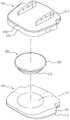
도 1 - 본 발명에 따른 인공 디스크의 상판에서 본 분해사시도.
도 2 - 본 발명에 따른 인공 디스크의 하판에서 본 분해사시도.
도 3 - 본 발명에 따른 인공 디스크의 결합사시도.
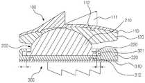
도 4 - 본 발명에 따른 인공 디스크의 단면도.
도 5 - 본 발명에 따른 인공 디스크의 구체적인 유동각도를 나타낸 도.
도 6 - 본 발명에 따른 인공 디스크의 제조방법에 대한 모식도.FIG. 1 is an exploded perspective view of an artificial disc according to the present invention. FIG.
FIG. 2 is an exploded perspective view of the lower plate of the artificial disk according to the present invention. FIG.
3 is a perspective view of the artificial disc according to the present invention;
4 is a sectional view of an artificial disk according to the present invention.
5 is a view showing a specific angle of flow of an artificial disc according to the present invention.
6 is a schematic view of a method of manufacturing an artificial disc according to the present invention.
본 발명은 인체의 노화에 따른 퇴행성 척추 질환, 외부의 충격 및 올바르지 않은 자세에 따른 디스크의 손상 및 이탈로 인한 디스크 이상에 대한 수술적 치료에 사용하기 위한 인공 디스크에 관한 것이다.The present invention relates to an artificial disc for use in surgical treatment of a disc abnormality due to degenerative spinal disease caused by aging of a human body, external impact and damage and deviation of the disc due to incorrect posture.
특히, 중간체의 결합면에 접촉하는 상판과 하판을 중간체와 동일한 재질로 형성하여 인공 디스크의 내구성을 향상시키고, 인공 디스크에 대한 구조를 개선하여 인체의 움직임이나, 외부 충격 등에 의해서도 충격이 완화될 수 있도록 하는 것이다.
Particularly, the upper plate and the lower plate which are in contact with the coupling surface of the intermediate body are made of the same material as the intermediate body to improve the durability of the artificial disk, and the structure of the artificial disk is improved, so that the impact can be alleviated by the movement of the human body, .
이하에서는 첨부된 도면을 참조하여 본 발명에 대해 상세히 설명하고자 한다.Hereinafter, the present invention will be described in detail with reference to the accompanying drawings.
도 1은 본 발명에 따른 인공 디스크의 상판에서 본 분해사시도이고, 도 2는 본 발명에 따른 인공 디스크의 하판에서 본 분해사시도이고, 도 3은 본 발명에 따른 인공 디스크의 결합사시도이며, 도 4는 본 발명에 따른 인공 디스크의 단면도이며, 도 5는 본 발명에 따른 인공 디스크의 구체적인 유동각도를 나타낸 도이다.
FIG. 1 is an exploded perspective view of an artificial disc according to the present invention, FIG. 2 is an exploded perspective view of an artificial disc according to the present invention, FIG. 3 is an assembled perspective view of an artificial disc according to the present invention, FIG. 5 is a view showing a specific angle of flow of an artificial disc according to the present invention. FIG.
도시된 바와 같이 본 발명에 따른 인공 디스크는, 인접하는 척추뼈 사이에 각각 고정되는 상판(100)과, 하판(300), 그리고 상기 상판(100) 및 하판(300) 사이에 결합되는 중간체로 이루어진 인공 디스크에 있어서, 상면에 복수개의 스파이크가 형성되고, 하면에는 인서트돌기가 형성된 제1상판부재와, 상기 제1상판부재의 하면에 인서트사출형성되며, 상기 제1상판부재와는 이종(異種)의 재질로 형성되고 하면에 오목홈(121)이 형성된 제2상판부재(120)로 이루어진 상판(100)과, 상기 상판(100)의 오목홈(121)에 결합되도록 상측에 볼록부(210)가 형성되어, 상기 상판(100)이 상기 볼록부(210)를 따라 유동하도록 형성되며, 하단 테두리에는 결합구(220)가 형성되고, 상기 제2상판부재(120)와 동일한 재질로 형성된 중간체(200)와, 하면에 복수개의 킬이 형성되고, 상면에는 인서트돌기가 형성된 제1하판부재(310)와, 상기 제1하판부재(310)의 상면에 인서트사출형성되며, 상기 제1하판부재(310)와는 이종(異種)의 재질, 상기 중간체(200)와는 동일한 재질로 형성되고, 상기 중간체(200)의 결합구(220)가 수용결합되도록 결합홈(321)이 형성된 제2하판부재(320)로 이루어진 하판(300)으로 크게 이루어진다.
The artificial disc according to the present invention includes an
본 발명은 인체의 노화에 따른 퇴행성 척추 질환, 외부의 충격 및 올바르지 않은 자세에 따른 디스크의 손상 및 이탈로 인한 디스크 이상에 대한 수술적 치료에 사용하기 위한 것으로, 먼저 손상된 디스크를 제거하고, 상판(100) 및 하판(300) 사이에 중간체(200)를 결합한 후, 상측 척추뼈의 하면에 상판(100)을 고정시키고, 인접하는 하측 척추뼈의 상면에 상판(100)을 고정시키는 것에 의해 수술적 치료를 수행하는 것이다. The present invention is intended to be used for surgical treatment of a disc abnormality due to degenerative spinal disease, external shock, and incorrect posture due to aging of a human body. First, the damaged disc is removed, The
먼저, 상판(100)은 상면에 복수개의 스파이크(111)가 형성되고, 하면에는 인서트돌기가 형성된 제1상판부재(110)와, 상기 제1상판부재(110)의 하면에 인서트사출형성되며, 상기 제1상판부재(110)와는 이종(異種)의 재질로 형성되고 하면에 오목홈(121)이 형성된 제2상판부재(120)로 이루어진다.The
상기 스파이크(111)는 척추뼈 사이의 삽입을 용이하게 하기 위한 것으로서, 상기 상판(100)의 상면에 돌출된 형태로 형성된다. 구체적으로는, 상기 척추뼈 사이에 삽입이 되는 방향으로 경사지게 형성되면서, 그 반대 방향으로는 그 보다 큰 경사도를 가지도록 형성되어, 척추뼈 사이에 삽입이 잘 이루어지도록 하면서, 척추뼈에 고정도 잘 되도록 한다.The
상기 스파이크(111)는 필요에 따라 적절한 갯수로 형성하며, 본 발명에서의 바람직한 실시예로는 도면에 도시한 바와 같이 3개 정도 형성하였다.The
그리고, 상기 상판(100)은 제1상판부재(110)와 제2상판부재(120)로 형성되는데, 상기 제1상판부재(110)와 제2상판부재(120)는 이종(異種)의 재질로 형성되어, 상기 제1상판부재(110)의 하면에 인서트사출되어 형성된다. 제1상판부재(110)에 형성된 인서트돌기(112)에 의해 제1상판부재와 제2상판부재와의 결합력이 증가되어 내구성을 향상시키게 된다.The
즉, 제1상판부재(110)는 척추뼈에 고정되게 되어 인체의 활동에도 이탈이 되지 않아야 하므로 보다 강도가 큰 재질로 형성되어야 하며, 완충역할을 하는 중간체(200)에 접하게 되는 제2상판부재(120)는 상기 중간체(200)의 마모를 최소화하기 위한 재질로 형성되어야 한다.That is, since the first
구체적으로는 상기 제1상판부재(110)는 금속 재질로 형성되며, 상기 제2상판부재(120)는 폴리머 재질로 형성되는 것이 바람직하다.Specifically, the first
상기 제1상판부재(110)를 금속으로 제조하는 경우에는 티타늄, 티타늄 합금, 스테인레스 등을 사용한다.When the first
상기 제2상판부재(120)는 중간체(200)와 동일한 재질인 폴리머로 형성되며, 바람직하게는 폴리에틸렌, 폴리에테르에테르 케톤(PEEK), 폴리에테르 케톤 케톤(PEKK), 폴리에테르 케톤(PEK) 등의 재질을 사용한다.The second
여기에서, 상기 제2상판부재(120)의 하면에는 오목홈(121)이 형성되어, 후술할 중간체(200)의 볼록부(210)와 결합되게 된다.The
한편, 상기 제1상판부재(110)는 3D 프린팅에 의해 스파이크(111) 및 인서트돌기(112)가 형성된 제1상판재를 형성한 후, 인서트사출하여 상기 제1상판부재의 하면에 상기 제2상판재를 형성한 후, 절삭가공함으로써 상기 제2상판부재(120)에 오목홈(121)을 형성하는 등 최종 상판(100)의 형상에 따라 제조되게 된다.The first
상기 절삭가공시 필요에 의해 상기 제1상판부재(110)의 상면에는 척추뼈에의 견고한 결합을 위해 요철을 형성할 수도 있으며, 척추뼈에의 삽입시 수술기구 등을 이용하여 시술할 수 있도록 결합공 등을 형성할 수도 있다.
If necessary, the upper surface of the first
그리고, 상기 중간체(200)는 상기 상판(100)의 오목홈(121)에 결합되도록 상측에 볼록부(210)가 형성되어, 상기 볼록부(210)를 따라 유동하도록 형성되며, 하단 테두리에는 결합구(220)가 형성되고, 상기 제2상판부재(120)와 동일한 재질로 형성된다.The
상기 중간체(200)는 전체적으로 반구형 또는 타원형 등의 형태로 상측으로 볼록하게 볼록부(210)가 형성된 형태를 가지며, 중간체(200)의 볼록부(210) 면을 따라 상기 상판(100)이 일정 각도로 유동되도록 형성되는 것이다.The
그리고, 상기 중간체(200)의 하단 테두리에는 후술할 하판(300)의 결합홈(321)에 일정 유격을 가지도록 결합되는 결합구(220)가 형성되어, 상판(100)의 움직임을 제한하면서도, 인체의 해부학적 움직임에 따라 일정 각도 내에서 상기 중간체(200)의 볼록면을 따라 상판(100)이 유연하게 유동되도록 하고, 중간체(200)의 움직임이 자유롭도록 한다.A
이에 의해 중간체(200)에 미치는 하중을 효율적으로 분산시켜, 척추에 미치는 응력을 골고루 분산하며, 그 충격을 완화하고, 내구성을 향상시키도록 하는 것이다.By this, the load applied to the
상기 중간체(200)는 앞서 서술한 바와 같이, 상기 제2상판부재(120)와 동일한 재질로 형성되어, 이종 재질 간의 접촉 및 상기 상판(100)의 움직임에 따른 마모 및 충격이 최소화되도록 하여, 제품의 내구성을 향상시킴과 아울러 그 기능이 오래도록 변함없도록 하면서, 환자의 신체 내부로 미세입자들이 돌아다니는 위험을 최소화하도록 한 것이다.
As described above, the
그리고, 상기 하판(300)은 하면에 복수개의 킬(keel)(311)이 형성되고, 상면에 인서트돌기(312)가 형성된 제1하판부재(310)와, 상기 제1하판부재(310)의 상면에 인서트사출형성되며, 상기 제1하판부재(310)와는 이종(異種)의 재질, 상기 중간체(200)와는 동일한 재질로 형성되고, 상기 중간체(200)의 결합구(220)가 수용결합되도록 결합홈(321)이 형성된 제2하판부재(320)로 이루어진 것이다.The
상기 킬(keel)(311)은 척추뼈 사이의 삽입을 용이하게 하고, 견고하게 고정시키기 위한 것으로서, 상기 하판(300)의 하면에 돌출된 형태로 형성된다. 구체적으로는, 일정 높이를 가지면서 상기 척추뼈 사이에 삽입이 되는 방향으로 경사지게 형성된 것이다. 보다 견고한 척추뼈에의 고정을 위해서 척추뼈의 별도의 고정홈을 형성하여 상기 킬(keel)(311)을 결합할 수도 있다.The
상기 킬(keel)(311)은 필요에 따라 적절한 갯수로 형성하며, 본 발명에서의 바람직한 실시예로는 도면에 척추뼈에의 삽입 방향으로 나란히 두개 정도 형성하였다.The
그리고, 상기 하판(300)은 제1하판부재(310)와 제2하판부재(320)로 형성되는데, 상기 제1하판부재(310)와 제2하판부재(320)는 이종(異種)의 재질로 형성되어, 상기 제1하판부재(310)의 타면에 인서트사출되어 형성된다. 제1하판부재(310)에 형성된 인서트돌기(312)에 의해 제1하판부재와 제2하판부재와의 결합력이 증가되어 내구성을 향상시키게 된다.The
즉, 제1하판부재(310)는 척추뼈에 고정되게 되어 인체의 활동에도 이탈이 되지 않아야 하므로 보다 강도가 큰 재질로 형성되어야 하며, 완충역할을 하는 중간체(200)에 접하게 되는 제2하판부재(320)는 상기 중간체(200)의 마모를 최소화하기 위한 재질로 형성되어야 한다.That is, since the first
구체적인 것은 상기 제1상판부재(110)는 제1하판부재(310), 제2상판부재(120)는 제2하판부재(320)와 재료 및 그 제조방법 상의 설명이 상기 상판(100)에서와 동일하므로, 여기에서는 생략하도록 한다.Specifically, the first
또한, 상기 제2하판부재(320)의 상면에는 상기 중간체(200)의 결합구(220)가 수용결합되도록 결합홈(321)이 형성되어, 상기 중간체(200)의 결합구(220)가 결합홈(321)에 수용결합되면서, 상기 중간체(200)는 상기 하판(300)에 고정되게 된다.A
여기에서, 도 4에 도시된 바와 같이, 상기 중간체(200)의 결합구(220)와 상기 제2하판부재(320)의 결합홈(321) 사이에는 0.48~0.52mm, 더욱 바람직하게는 최대 0.50mm의 유격이 형성된다.4, between the
이는 상판(100) 및 중간체(200)의 움직임을 제한하면서도, 인체의 해부학적 움직임에 따라 일정 각도 내에서 상기 중간체(200)의 볼록면을 따라 상판(100)이 유연하게 유동되도록 하고, 중간체(200)의 병진 운동이 허용되는 등 중간체(200)의 움직임이 자유롭도록 하여, 중간체(200)에 미치는 하중을 효율적으로 분산시키기 위한 것이다.
This allows the
한편, 도 5에 도시된 바와 같이, 상기 중간체(200)를 중심으로 상기 상판(100)은 유동되도록 형성되며, 척추뼈 사이에 고정이 시작되는 일측에서의 상기 상판(100)의 유동각도는 상기 하판(300)에 대해 최대 9.00°~ 9.02°, 척추뼈 사이에 고정이 완료되는 타측에서의 상기 상판(100)의 유동각도는 상기 하판(300)에 대해 최대 8.39°~ 8.41°, 측면에서의 상기 상판(100)의 유동각도는 최대 5.77°~ 5.79°, 더욱 바람직하게는 척추뼈 사이에 고정이 시작되는 일측에서의 상기 상판(100)의 유동각도는 상기 하판(300)에 대해 9.01°, 척추뼈 사이에 고정이 완료되는 타측에서의 상기 상판(100)의 유동각도는 상기 하판(300)에 대해 8.40°, 측면에서의 상기 상판(100)의 유동각도는 5.78°이다.5, the
상기 상판(100)의 유동각도를 제한하되, 이 범위내에서는 자유롭게 상기 중간체(200)의 볼록면을 따라 상판(100)이 유동되도록 하면서, 상기 중간체(200) 자체의 병진 운동도 가능하도록 한 것이다.The angle of flow of the
이에 의해 중간체(200)에 미치는 하중이 골고록 분산되도록 하면서, 그 하중을 최소화하도록 하고, 인체의 해부학적 움직임을 고려하여, 어느 범위 내에서는 움직임이 제한되도록 하여, 인체의 운동 중심과 디스크의 움직임에 따른 중심이 상호 신속하게 일치되도록 하여, 상하측 척추뼈의 불일치에 따른 불연속적인 움직임으로 척추뼈에 작용하는 응력을 분산시켜 디스크에 미치는 하중을 최소화할 수 있도록 하는 것이다.
Thus, while the load applied to the
이하에서는 본 발명에 따른 인공 디스크의 제조방법에 대해 설명하고자 한다. 도 6은 본 발명에 따른 인공 디스크의 제조방법에 대한 모식도를 나타내 것이다.Hereinafter, a method of manufacturing an artificial disc according to the present invention will be described. 6 is a schematic view of a method for manufacturing an artificial disc according to the present invention.
도시된 바와 같이, 본 발명에 따른 인공 디스크의 제조방법은 인접하는 척추뼈 사이에 각각 고정되는 상판(500)과, 하판(600), 그리고 상기 상판(500) 및 하판(600) 사이에 결합되는 중간체(700)로 이루어진 인공 디스크의 제조방법에 있어서, 일면에 복수 개의 스파이크(511)가 형성되고, 타면에는 인서트돌기가 형성된 제1상판재(510)를 제조하는 단계와, 상기 제1상판재(510)의 타면에 제2상판재(520)를 인서트사출하는 단계와, 상기 제1상판재(510) 및 오목홈이 형성되도록 제2상판재(520)를 절삭가공하여 상판(500)을 제조하는 단계와, 일면에 복수개의 킬(keel)(611)이 형성되고, 타면에는 인서트돌기가 형성된 제1하판재를 제조하는 단계와, 상기 제1하판재(610)의 타면에 제2하판재(620)를 인서트사출하는 단계와, 상기 제1하판재(610) 및 결합홈이 형성되도록 제2하판재(620)를 절삭가공하여 하판(600)을 제조하는 단계와, 상기 제2상판재(520) 및 제2하판재(620)와 동일한 재질을 사용하며, 상측에는 상기 오목홈에 결합되도록 볼록부를 형성하고, 하단 테두리에는 상기 결합홈에 결합되도록 결합구를 형성하도록 중간체(700)를 제조하는 단계로 크게 이루어진다.As shown, the artificial disc manufacturing method according to the present invention includes an upper plate 500, a lower plate 600, and a lower plate 600 coupled between adjacent upper and lower vertebrae 500 and 600, A method for manufacturing an artificial disc comprising an intermediate body (700), comprising the steps of: preparing a first upper plate member (510) having a plurality of spikes (511) formed on one surface thereof and insert protrusions formed on the other surface thereof; A step of inserting a second upper plate member 520 on the other surface of the upper plate member 510 and cutting the second upper plate member 520 to form the first upper plate member 510 and the concave groove, (611) on one side and insert protrusions on the other side; and a second lower plate (610) on the other side of the first lower plate (610) A step of inserting the plate material 620 and a step of inserting the plate material 620 into the second lower plate material 620 to form the first lower plate material 610 and the coupling groove, A step of forming a lower plate 600 by cutting the upper plate member 520 and a lower plate 600 using the same material as that of the second upper plate member 520 and the second lower plate member 620 and forming a convex portion on the upper side to be engaged with the concave groove, And a step of manufacturing the intermediate body 700 so as to form a coupling hole to be coupled to the coupling groove.
먼저, 상기 상판(500)을 제조하기 위해서, 일면에 복수개의 스파이크(511)가 형성되고, 타면에는 인서트돌기(512)가 형성된 제1상판재(510)를 제조하고, 상기 제1상판재(510)의 타면에 제2상판재(520)를 인서트사출한 후, 이를 절삭가공하여 상판(500)을 제조하게 된다.First, to manufacture the
상기 제1상판재(510)는 상기 제1상판부재(110)를 형성하기 위한 것으로서, 재질은 상술한 바와 같이 금속 재질로 형성되게 되며, 상기 제2상판재(520)는 상기 제2상판부재를 형성하기 위한 것으로서, 폴리머 재질로 형성되는 것이 바람직하다.The first
상기 제1상판재(510)는 판상으로 형성되며, 상기 제1상판부재(110)의 형태를 고려하여 상측으로 볼록한 곡면을 가지도록 가공된다. 상기 제1상판재(510)의 가공방법은 3D 프린팅에 의해 성형된다.The first
상기 제2상판재(520)는 판상으로 형성되며, 상기 제2상판부재의 두께 및 형태를 고려하여 인서트사출로 성형된다.The second
상기 제1상판재(510)의 타면에 제2상판재(520)를 인서트사출한 후, 기계적 절삭 가공방법에 의해 오목홈이 형성된 최종 상판(500)의 형태로 형성된다.The second
그리고, 상기 하판(600)도 상기 상판(500)과 동일한 과정에 의해 제작되어, 결합홈이 형성된 최종 하판(600)의 형태로 형성된다.The
그리고, 상기 중간체(700)는 상기 제2상판재(520)와 제2하판재(620)와 동일한 재질을 사용하므로, 사출성형에 의해 제작되며, 상측에는 상기 오목홈에 결합되도록 볼록부를 형성하고, 하단 테두리에는 상기 결합홈에 결합되도록 결합구를 형성하게 된다.
Since the
이와 같이 본 발명은, 중간체의 결합면에 접촉하는 상판과 하판을 중간체와 동일한 재질로 형성하여 인공 디스크의 내구성을 향상시키고, 인공 디스크에 대한 구조를 개선하여 인체의 움직임이나, 외부 충격 등에 의해서도 충격이 분산, 완화될 수 있도록 한 것이다.As described above, according to the present invention, it is possible to improve the durability of an artificial disc by forming the upper plate and the lower plate in contact with the coupling surface of the intermediate body with the same material as the intermediate body, To be dispersed and mitigated.
특히, 상기 중간체는 상기 제2상판부재 및 제2하판부재와 동일한 재질로 형성하여 상기 상판의 움직임에 따른 마모 및 충격이 최소화되도록 하여, 제품의 내구성을 향상시킴과 아울러 그 기능이 오래도록 변함없도록 하면서, 환자의 신체 내부로 미세입자들이 돌아다니는 위험을 최소화하여 안전한 사용이 가능하도록 한 것이다.Particularly, the intermediate member is made of the same material as the second upper plate member and the second lower plate member, minimizing wear and impact caused by the movement of the upper plate, thereby improving the durability of the product, , Minimizing the risk of microparticles moving inside the patient's body, thereby enabling safe use.
또한, 상기 상판의 유동각도를 제한하되, 이 범위내에서는 자유롭게 상기 중간체의 볼록면을 따라 상판이 유동되도록 하면서, 상기 중간체 자체의 병진 운동도 가능하도록 하여, 상기 중간체에 미치는 하중이 골고루 분산되도록 한 것이다.It is also possible to limit the flow angle of the upper plate and to allow the upper plate to flow freely along the convex surface of the intermediate body within the range so that the intermediate body itself can be translated and the load applied to the intermediate body is evenly distributed will be.
100 : 상판110 : 제1상판부재
111 : 스파이크112 : 인서트돌기
120 : 제2상판부재121 : 오목홈
200 : 중간체210 : 볼록부
220 : 결합구300 : 하판
310 : 제1하판부재311 : 킬(keel)
312 : 인서트돌기320 : 제2하판부재
321 : 결합홈
500 : 상판510 : 제1상판재
511 : 스파이크512 : 인서트돌기
520 : 제2상판재600 : 하판
610 : 제1하판재611 : 킬(keel)
612 : 인서트돌기620 : 제2하판재
700 : 중간체100: upper plate 110: first upper plate member
111: spike 112: insert projection
120: second upper plate member 121: concave groove
200: Intermediate 210:
220: Coupling port 300: Lower plate
310: first lower plate member 311: keel
312: insert projection 320: second lower plate member
321: Coupling groove
500: upper plate 510: first upper plate member
511: spike 512: insert projection
520: second upper plate member 600: lower plate
610: first bottom plate 611: keel
612: insert projection 620: second bottom plate
700: Intermediate
Claims (10)
Translated fromKorean일면에 복수개의 스파이크가 형성되고, 타면에는 인서트돌기가 형성된 제1상판재를 제조하는 단계;
상기 제1상판재의 타면에 제2상판재를 인서트사출하는 단계;
상기 제1상판재 및 오목홈이 형성되도록 제2상판재를 절삭가공하여 상판을 제조하는 단계;
일면에 복수개의 킬이 형성되고, 타면에는 인서트돌기가 형성된 제1하판재를 제조하는 단계;
상기 제1하판재의 타면에 제2하판재를 인서트사출하는 단계;
상기 제1하판재 및 결합홈이 형성되도록 제2하판재를 절삭가공하여 하판을 제조하는 단계;
상기 제2상판재 및 제2하판재와 동일한 재질을 사용하며, 상측에는 상기 오목홈에 결합되도록 볼록부를 형성하고, 하단 테두리에는 상기 결합홈에 결합되도록 결합구를 형성하도록 중간체를 제조하는 단계;를 포함하여 이루어지는 것을 특징으로 하는 인공 디스크의 제조방법.A method for manufacturing an artificial disc comprising an upper plate fixed between adjacent vertebrae, a lower plate, and an intermediate member interposed between the upper plate and the lower plate,
The method comprising: fabricating a first upper plate member on which a plurality of spikes are formed on one surface and insert protrusions are formed on the other surface;
Inserting a second upper plate member onto the other surface of the first upper plate member;
Cutting the second upper plate member so as to form the first upper plate member and the concave groove, thereby manufacturing an upper plate;
The method comprising: fabricating a first lower plate having a plurality of keels formed on one surface thereof and insert protrusions formed on the other surface thereof;
Inserting a second lower sheet material onto the other surface of the first lower sheet material;
Cutting the second lower plate so that the first lower plate and the coupling groove are formed;
Preparing an intermediate body using the same material as the second upper plate member and the second lower plate member, forming a convex portion on the upper side to form the concave groove, and forming a coupling hole on the lower side of the lower plate member to be coupled to the coupling groove; And forming a synthetic resin layer on the surface of the artificial disc.
상기 제2상판재 및 제2하판재와 이종(異種)의 재질로 형성되는 것을 특징으로 하는 인공 디스크의 제조방법.[2] The apparatus of claim 1, wherein the first upper plate member and the first lower plate member comprise:
Wherein the first upper plate member and the second lower plate member are made of different materials from the second upper plate member and the second lower plate member.
금속으로 형성되는 것을 특징으로 하는 인공 디스크의 제조방법.[3] The apparatus of claim 2, wherein the first upper plate member and the first lower plate member comprise:
Wherein the metal plate is formed of a metal.
폴리머로 형성되는 것을 특징으로 하는 인공 디스크의 제조방법.The method according to claim 2, wherein the second upper plate member, the second lower plate member,
Wherein the polymer is formed of a polymer.
상면에 복수개의 스파이크가 형성된 제1상판부재와, 상기 제1상판부재에 인서트사출형성되며, 상기 제1상판부재와는 이종(異種)의 재질로 형성되고 하면에 오목홈이 형성된 제2상판부재로 이루어진 상판;
상기 상판의 오목홈에 결합되도록 상측에 볼록부가 형성되어, 상기 상판이 상기 볼록부를 따라 유동하도록 형성되며, 하단 테두리에는 결합구가 형성되고, 상기 제2상판부재와 동일한 재질로 형성된 중간체;
하면에 복수개의 킬이 형성된 제1하판부재와, 상기 제1하판부재에 인서트사출형성되며, 상기 제1하판부재와는 이종(異種)의 재질, 상기 중간체와는 동일한 재질로 형성되고, 상기 중간체의 결합구가 수용결합되도록 결합홈이 형성된 제2하판부재로 이루어진 하판;을 포함하여 이루어진 것을 특징으로 하는 인공 디스크.An artificial disc comprising an upper plate fixed between adjacent vertebrae, a lower plate, and an intermediate member interposed between the upper plate and the lower plate,
A first upper plate member having an upper surface formed with a plurality of spikes on an upper surface thereof, a second upper plate member formed by insert injection into the first upper plate member and formed of a material different from that of the first upper plate member, ;
An intermediate body formed with a convex portion on an upper side to be coupled to the concave groove of the upper plate so that the upper plate is formed to flow along the convex portion, a coupling hole is formed on the lower edge, and the same material as the second upper plate member;
A first lower plate member on which a plurality of kills are formed on an upper surface of the first lower plate member and a second lower plate member on which an insert is injected and formed, And a second lower plate member having an engaging groove formed therein so as to receive and engage the engaging holes of the lower plate.
금속으로 형성되는 것을 특징으로 하는 인공 디스크.[7] The apparatus of claim 6, wherein the first upper plate member and the first lower plate member comprise:
Wherein the metal plate is formed of a metal.
폴리머로 형성되는 것을 특징으로 하는 인공 디스크.7. The method according to claim 6, wherein the second upper plate member, the second lower plate member,
Wherein the first layer is formed of a polymer.
Priority Applications (1)
| Application Number | Priority Date | Filing Date | Title |
|---|---|---|---|
| KR1020140156969AKR101629708B1 (en) | 2014-11-12 | 2014-11-12 | Manufacturing method of artificial intervertebral disc and artificial intervertebral disc thereby |
Applications Claiming Priority (1)
| Application Number | Priority Date | Filing Date | Title |
|---|---|---|---|
| KR1020140156969AKR101629708B1 (en) | 2014-11-12 | 2014-11-12 | Manufacturing method of artificial intervertebral disc and artificial intervertebral disc thereby |
Publications (2)
| Publication Number | Publication Date |
|---|---|
| KR20160056568A KR20160056568A (en) | 2016-05-20 |
| KR101629708B1true KR101629708B1 (en) | 2016-06-13 |
Family
ID=56103715
Family Applications (1)
| Application Number | Title | Priority Date | Filing Date |
|---|---|---|---|
| KR1020140156969AActiveKR101629708B1 (en) | 2014-11-12 | 2014-11-12 | Manufacturing method of artificial intervertebral disc and artificial intervertebral disc thereby |
Country Status (1)
| Country | Link |
|---|---|
| KR (1) | KR101629708B1 (en) |
Cited By (1)
| Publication number | Priority date | Publication date | Assignee | Title |
|---|---|---|---|---|
| KR20210154533A (en)* | 2020-06-12 | 2021-12-21 | (주) 서한케어 | Artificial disc |
Families Citing this family (1)
| Publication number | Priority date | Publication date | Assignee | Title |
|---|---|---|---|---|
| CN110368148B (en)* | 2019-08-05 | 2024-05-28 | 北京爱康宜诚医疗器材有限公司 | Flexible artificial intervertebral disc |
Citations (2)
| Publication number | Priority date | Publication date | Assignee | Title |
|---|---|---|---|---|
| JP2007518453A (en) | 2003-08-01 | 2007-07-12 | スパイナル カネティックス, インコーポレイテッド | Prosthetic intervertebral disc and method of use thereof |
| KR100948420B1 (en) | 2009-03-05 | 2010-03-19 | 주식회사 지에스메디칼 | An artificial spinal disc |
Family Cites Families (4)
| Publication number | Priority date | Publication date | Assignee | Title |
|---|---|---|---|---|
| FR2787018B1 (en) | 1998-12-11 | 2001-03-02 | Dimso Sa | INTERVERTEBRAL DISC PROSTHESIS WITH LIQUID ENCLOSURE |
| KR20090118365A (en)* | 2008-05-13 | 2009-11-18 | 윤강준 | Intervertebral calibrator |
| DE112010005471T5 (en)* | 2010-04-09 | 2013-01-17 | Synthes Gmbh | End plate of an intervertebral implant and implant |
| KR101397192B1 (en) | 2013-12-18 | 2014-05-19 | 윤홍원 | Intervertebral tentional artificial disc replacement |
- 2014
- 2014-11-12KRKR1020140156969Apatent/KR101629708B1/enactiveActive
Patent Citations (2)
| Publication number | Priority date | Publication date | Assignee | Title |
|---|---|---|---|---|
| JP2007518453A (en) | 2003-08-01 | 2007-07-12 | スパイナル カネティックス, インコーポレイテッド | Prosthetic intervertebral disc and method of use thereof |
| KR100948420B1 (en) | 2009-03-05 | 2010-03-19 | 주식회사 지에스메디칼 | An artificial spinal disc |
Cited By (2)
| Publication number | Priority date | Publication date | Assignee | Title |
|---|---|---|---|---|
| KR20210154533A (en)* | 2020-06-12 | 2021-12-21 | (주) 서한케어 | Artificial disc |
| KR102484143B1 (en)* | 2020-06-12 | 2023-01-04 | (주)서한케어 | Artificial disc |
Also Published As
| Publication number | Publication date |
|---|---|
| KR20160056568A (en) | 2016-05-20 |
Similar Documents
| Publication | Publication Date | Title |
|---|---|---|
| US20220151802A1 (en) | Interbody standalone intervertebral implant | |
| ES2710148T3 (en) | Orthopedic medical device | |
| US8066742B2 (en) | Intervertebral prosthetic device for spinal stabilization and method of implanting same | |
| KR20140079512A (en) | Spinal interbody device | |
| WO2009091775A2 (en) | Intervertebral cage and vertebral fusion device | |
| AU2017380627B2 (en) | Intervertebral disk prosthesis and method for producing an intervertebral disk prosthesis | |
| US8945228B2 (en) | Endplate for a vertebral implant | |
| KR101297982B1 (en) | Apparatus for fixing spine with cage unit | |
| KR101964862B1 (en) | Artificial disc for cervical vertebrae | |
| KR20110067044A (en) | Surgical connector attaches long member to bone | |
| KR20130032575A (en) | Spinal implant | |
| KR101629708B1 (en) | Manufacturing method of artificial intervertebral disc and artificial intervertebral disc thereby | |
| US7803192B2 (en) | Artificial intervertebral disc | |
| KR100972397B1 (en) | Intervertebral implant | |
| TWI768260B (en) | Vertebra reconstruction implant | |
| KR100980451B1 (en) | A cage with spike for intervertebral discs | |
| WO2015109414A1 (en) | Facet joint prosthesis | |
| JP5384337B2 (en) | Intervertebral implant for bone fusion and manufacturing method thereof | |
| WO2014077818A1 (en) | Endplate for a vertebral implant | |
| KR102567560B1 (en) | Spine fixation device | |
| US20210196467A1 (en) | Disc prosthesis for cervical vertebra having elasticity similar to that of bone tissue | |
| KR101281804B1 (en) | Spinal implant apparatus | |
| US12426929B2 (en) | Dynamic bone plate and method of use | |
| KR101009937B1 (en) | Intervertebral Implants | |
| KR101272233B1 (en) | An artificial disc for vertebra |
Legal Events
| Date | Code | Title | Description |
|---|---|---|---|
| PA0109 | Patent application | Patent event code:PA01091R01D Comment text:Patent Application Patent event date:20141112 | |
| PA0201 | Request for examination | ||
| PG1501 | Laying open of application | ||
| E701 | Decision to grant or registration of patent right | ||
| PE0701 | Decision of registration | Patent event code:PE07011S01D Comment text:Decision to Grant Registration Patent event date:20160523 | |
| GRNT | Written decision to grant | ||
| PR0701 | Registration of establishment | Comment text:Registration of Establishment Patent event date:20160607 Patent event code:PR07011E01D | |
| PR1002 | Payment of registration fee | Payment date:20160607 End annual number:3 Start annual number:1 | |
| PG1601 | Publication of registration | ||
| FPAY | Annual fee payment | Payment date:20190605 Year of fee payment:4 | |
| PR1001 | Payment of annual fee | Payment date:20190605 Start annual number:4 End annual number:4 | |
| PR1001 | Payment of annual fee | Payment date:20200601 Start annual number:5 End annual number:5 | |
| PR1001 | Payment of annual fee | Payment date:20230601 Start annual number:8 End annual number:8 | |
| PR1001 | Payment of annual fee | Payment date:20240516 Start annual number:9 End annual number:9 | |
| PR1001 | Payment of annual fee | Payment date:20250528 Start annual number:10 End annual number:10 |