KR101629653B1 - Heat radiation unit for a wireless charging and wireless charging module having the same - Google Patents
Heat radiation unit for a wireless charging and wireless charging module having the sameDownload PDFInfo
- Publication number
- KR101629653B1 KR101629653B1KR1020150110180AKR20150110180AKR101629653B1KR 101629653 B1KR101629653 B1KR 101629653B1KR 1020150110180 AKR1020150110180 AKR 1020150110180AKR 20150110180 AKR20150110180 AKR 20150110180AKR 101629653 B1KR101629653 B1KR 101629653B1
- Authority
- KR
- South Korea
- Prior art keywords
- sheet
- layer
- antenna
- slot
- unit
- Prior art date
- Legal status (The legal status is an assumption and is not a legal conclusion. Google has not performed a legal analysis and makes no representation as to the accuracy of the status listed.)
- Active
Links
Images


Classifications
- H—ELECTRICITY
- H05—ELECTRIC TECHNIQUES NOT OTHERWISE PROVIDED FOR
- H05K—PRINTED CIRCUITS; CASINGS OR CONSTRUCTIONAL DETAILS OF ELECTRIC APPARATUS; MANUFACTURE OF ASSEMBLAGES OF ELECTRICAL COMPONENTS
- H05K7/00—Constructional details common to different types of electric apparatus
- H05K7/20—Modifications to facilitate cooling, ventilating, or heating
- H05K7/2089—Modifications to facilitate cooling, ventilating, or heating for power electronics, e.g. for inverters for controlling motor
- H05K7/209—Heat transfer by conduction from internal heat source to heat radiating structure
- H—ELECTRICITY
- H01—ELECTRIC ELEMENTS
- H01F—MAGNETS; INDUCTANCES; TRANSFORMERS; SELECTION OF MATERIALS FOR THEIR MAGNETIC PROPERTIES
- H01F27/00—Details of transformers or inductances, in general
- H01F27/34—Special means for preventing or reducing unwanted electric or magnetic effects, e.g. no-load losses, reactive currents, harmonics, oscillations, leakage fields
- H01F27/36—Electric or magnetic shields or screens
- H01F27/366—Electric or magnetic shields or screens made of ferromagnetic material
- H02J7/025—
- H—ELECTRICITY
- H01—ELECTRIC ELEMENTS
- H01F—MAGNETS; INDUCTANCES; TRANSFORMERS; SELECTION OF MATERIALS FOR THEIR MAGNETIC PROPERTIES
- H01F27/00—Details of transformers or inductances, in general
- H01F27/08—Cooling; Ventilating
- H01F27/22—Cooling by heat conduction through solid or powdered fillings
- H—ELECTRICITY
- H01—ELECTRIC ELEMENTS
- H01F—MAGNETS; INDUCTANCES; TRANSFORMERS; SELECTION OF MATERIALS FOR THEIR MAGNETIC PROPERTIES
- H01F38/00—Adaptations of transformers or inductances for specific applications or functions
- H01F38/14—Inductive couplings
- H—ELECTRICITY
- H01—ELECTRIC ELEMENTS
- H01Q—ANTENNAS, i.e. RADIO AERIALS
- H01Q1/00—Details of, or arrangements associated with, antennas
- H01Q1/02—Arrangements for de-icing; Arrangements for drying-out ; Arrangements for cooling; Arrangements for preventing corrosion
- H—ELECTRICITY
- H01—ELECTRIC ELEMENTS
- H01Q—ANTENNAS, i.e. RADIO AERIALS
- H01Q1/00—Details of, or arrangements associated with, antennas
- H01Q1/12—Supports; Mounting means
- H01Q1/22—Supports; Mounting means by structural association with other equipment or articles
- H—ELECTRICITY
- H01—ELECTRIC ELEMENTS
- H01Q—ANTENNAS, i.e. RADIO AERIALS
- H01Q1/00—Details of, or arrangements associated with, antennas
- H01Q1/12—Supports; Mounting means
- H01Q1/22—Supports; Mounting means by structural association with other equipment or articles
- H01Q1/2208—Supports; Mounting means by structural association with other equipment or articles associated with components used in interrogation type services, i.e. in systems for information exchange between an interrogator/reader and a tag/transponder, e.g. in Radio Frequency Identification [RFID] systems
- H—ELECTRICITY
- H02—GENERATION; CONVERSION OR DISTRIBUTION OF ELECTRIC POWER
- H02J—CIRCUIT ARRANGEMENTS OR SYSTEMS FOR SUPPLYING OR DISTRIBUTING ELECTRIC POWER; SYSTEMS FOR STORING ELECTRIC ENERGY
- H02J50/00—Circuit arrangements or systems for wireless supply or distribution of electric power
- H02J50/10—Circuit arrangements or systems for wireless supply or distribution of electric power using inductive coupling
- H—ELECTRICITY
- H02—GENERATION; CONVERSION OR DISTRIBUTION OF ELECTRIC POWER
- H02J—CIRCUIT ARRANGEMENTS OR SYSTEMS FOR SUPPLYING OR DISTRIBUTING ELECTRIC POWER; SYSTEMS FOR STORING ELECTRIC ENERGY
- H02J7/00—Circuit arrangements for charging or depolarising batteries or for supplying loads from batteries
- H02J7/02—Circuit arrangements for charging or depolarising batteries or for supplying loads from batteries for charging batteries from AC mains by converters
- H—ELECTRICITY
- H04—ELECTRIC COMMUNICATION TECHNIQUE
- H04B—TRANSMISSION
- H04B5/00—Near-field transmission systems, e.g. inductive or capacitive transmission systems
- H04B5/20—Near-field transmission systems, e.g. inductive or capacitive transmission systems characterised by the transmission technique; characterised by the transmission medium
- H04B5/24—Inductive coupling
- H—ELECTRICITY
- H04—ELECTRIC COMMUNICATION TECHNIQUE
- H04B—TRANSMISSION
- H04B5/00—Near-field transmission systems, e.g. inductive or capacitive transmission systems
- H04B5/70—Near-field transmission systems, e.g. inductive or capacitive transmission systems specially adapted for specific purposes
- H04B5/79—Near-field transmission systems, e.g. inductive or capacitive transmission systems specially adapted for specific purposes for data transfer in combination with power transfer
- H—ELECTRICITY
- H05—ELECTRIC TECHNIQUES NOT OTHERWISE PROVIDED FOR
- H05K—PRINTED CIRCUITS; CASINGS OR CONSTRUCTIONAL DETAILS OF ELECTRIC APPARATUS; MANUFACTURE OF ASSEMBLAGES OF ELECTRICAL COMPONENTS
- H05K7/00—Constructional details common to different types of electric apparatus
- H05K7/20—Modifications to facilitate cooling, ventilating, or heating
- H05K7/2039—Modifications to facilitate cooling, ventilating, or heating characterised by the heat transfer by conduction from the heat generating element to a dissipating body
- H05K7/20436—Inner thermal coupling elements in heat dissipating housings, e.g. protrusions or depressions integrally formed in the housing
- H05K7/20445—Inner thermal coupling elements in heat dissipating housings, e.g. protrusions or depressions integrally formed in the housing the coupling element being an additional piece, e.g. thermal standoff
- H05K7/20472—Sheet interfaces
- H—ELECTRICITY
- H05—ELECTRIC TECHNIQUES NOT OTHERWISE PROVIDED FOR
- H05K—PRINTED CIRCUITS; CASINGS OR CONSTRUCTIONAL DETAILS OF ELECTRIC APPARATUS; MANUFACTURE OF ASSEMBLAGES OF ELECTRICAL COMPONENTS
- H05K9/00—Screening of apparatus or components against electric or magnetic fields
- H05K9/0073—Shielding materials
- H05K9/0075—Magnetic shielding materials
- H—ELECTRICITY
- H02—GENERATION; CONVERSION OR DISTRIBUTION OF ELECTRIC POWER
- H02J—CIRCUIT ARRANGEMENTS OR SYSTEMS FOR SUPPLYING OR DISTRIBUTING ELECTRIC POWER; SYSTEMS FOR STORING ELECTRIC ENERGY
- H02J7/00—Circuit arrangements for charging or depolarising batteries or for supplying loads from batteries
- H02J7/00032—Circuit arrangements for charging or depolarising batteries or for supplying loads from batteries characterised by data exchange
- H02J7/00034—Charger exchanging data with an electronic device, i.e. telephone, whose internal battery is under charge
Landscapes
- Engineering & Computer Science (AREA)
- Power Engineering (AREA)
- Computer Networks & Wireless Communication (AREA)
- Microelectronics & Electronic Packaging (AREA)
- Signal Processing (AREA)
- Physics & Mathematics (AREA)
- Thermal Sciences (AREA)
- Cooling Or The Like Of Electrical Apparatus (AREA)
- Shielding Devices Or Components To Electric Or Magnetic Fields (AREA)
- Details Of Aerials (AREA)
- Waveguide Aerials (AREA)
Abstract
Translated fromKoreanDescription
Translated fromKorean본 발명은 방열유닛에 관한 것으로, 더욱 상세하게는 무선충전시 발생되는 열을 효과적으로 방열할 수 있는 무선 충전용 방열유닛 및 이를 포함하는 무선전력 충전모듈에 관한 것이다.BACKGROUND OF THE INVENTION 1. Field of the Invention The present invention relates to a heat dissipation unit, and more particularly, to a heat dissipation unit for wireless charging capable of effectively dissipating heat generated during wireless charging and a wireless power charging module including the same.
최근 휴대폰, 태블릿 PC 등을 비롯한 휴대 단말기에 RFID(Radio Frequency Identification: 무선식별), 근거리 무선통신(NFC), 무선충전(WPT), 대화형 펜 태블릿 등 다양한 기능이 추가되고 있다. Recently, various functions such as RFID (Radio Frequency Identification), short range wireless communication (NFC), wireless charging (WPT) and interactive pen tablet have been added to mobile terminals including mobile phones and tablet PCs.
NFC는 전자태그인 RFID의 하나로 13.56Mz 주파수 대역을 사용하는 비접촉식 근거리 무선통신 모듈로 10cm의 가까운 거리에서 단말기 간 데이터를 전송하는 기술을 말한다. NFC는 모바일 결제뿐만 아니라 파일 전송방식으로 슈퍼마켓이나 일반 상점에서 물품 정보나 방문객을 위한 여행 정보 전송, 교통, 출입통제 잠금장치 등에 광범위하게 활용된다.NFC is one of the RFID tags, which is a non-contact type short-range wireless communication module using 13.56Mz frequency band. It is a technology to transmit data between terminals at a distance of 10cm. NFC is widely used not only for mobile payments, but also for transferring travel information, transportation, and access control locks for goods information and visitors in supermarkets and general shops, as well as for file transfer.
또한, 최근 구글이 발표한 스마트폰에 구비된 ‘안드로이드 빔’에는 근거리 무선통신(NFC) 기반의 근거리 정보 송수신 기능으로서, 모바일 결제뿐만 아니라 사진·명함·파일·지도·웹사이트 등을 한 전화기에서 다른 전화기로 전달하는 기능을 제공하고 있다.In addition, recently announced by Google, 'Android Beam' included in the smart phone is a near-field wireless communication (NFC) -based short distance information transmission and reception function that not only allows mobile payment but also photo, business card, file, map, To other phones.
한편, 휴대 단말기에는 내장된 배터리를 무선으로 충전하기 위한 무선 충전 기능이 구비되고 있는데, 이러한 무선 충전은 휴대 단말기에 내장되는 무선전력 수신모듈과, 상기 무선전력 수신모듈에 전력을 공급하는 무선전력 송신모듈에 의해 이루어진다.Meanwhile, the portable terminal has a wireless charging function for wirelessly charging a built-in battery. The wireless charging includes a wireless power receiving module built in the portable terminal, a wireless power transmitting module for supplying power to the wireless power receiving module, Module.
또한, 무선 충전은 자기유도 방식과 자기공진 방식으로 분류되기도 하며, 무선전력 송신모듈에 대한 무선전력 수신모듈의 접근을 감지하는 방식에 따라 PMA 방식과 Qi 방식으로 분류되기도 한다.In addition, the wireless charging may be classified into a magnetic induction type and a self-resonance type, and may be classified into a PMA type and a Qi type depending on a method of detecting a wireless power receiving module accessing the wireless power transmitting module.
이때, 상기 무선전력 송신모듈 및 무선전력 수신모듈 중 적어도 일측에는 무선 충전시 발생되는 열을 외부로 방출하여 충전 효율을 높이기 위해 방열부재가 구비된다.At least one of the wireless power transmitting module and the wireless power receiving module is provided with a heat dissipating member for discharging heat generated during wireless charging to the outside to increase the charging efficiency.
예를 들어, 상기 방열부재로 열전도율이 좋은 흑연(예컨대 그라파이트)이 통상적으로 사용되고 있는데, 이러한 흑연은 다음과 같은 문제점이 있다.For example, graphite (for example, graphite) having a high thermal conductivity as the heat dissipating member is usually used. Such graphite has the following problems.
즉, 상기 흑연은 재료 자체의 열전도율이 좋아 방열효과는 우수하나, 흑연은 낮은 저항 등에 의해 와전류가 심하게 발생하므로 충전 효율이 떨어진다. 따라서, 우수한 방열효과와 함께 충전효율을 향상시킬 수 있는 방안이 요구되고 있다.That is, the graphite is excellent in the heat radiation effect because the material itself has a good thermal conductivity, but the graphite has bad charging efficiency due to severe eddy current due to low resistance and the like. Accordingly, there is a demand for a method capable of improving the charging efficiency with an excellent heat radiation effect.
본 발명자들은 예의 연구 및 실험을 반복한 결과, 방열유닛의 기재층의 표면에 일정길이를 갖는 적어도 하나의 슬롯을 형성하는 경우, 특히, 기재층의 표면에 무선 충전용 안테나 패턴과 직교하는 방향으로 슬롯을 형성하는 경우, 기재층의 표면에서 발생하는 와전류를 효과적으로 억제하여 충전 효율을 향상시킬 수 있다는 것을 반복적인 연구 및 실험을 통하여 지득하였다.The present inventors have conducted extensive research and experiments and found that when at least one slot having a certain length is formed on the surface of the base layer of the heat dissipation unit, It has been found through repeated research and experiment that it is possible to effectively suppress the eddy currents generated on the surface of the base layer and to improve the charging efficiency.
본 발명은 상기와 같은 점을 감안하여 안출한 것으로, 기재층의 열전도율은 유지하면서도 와전류 손실을 줄일 수 있는 무선 충전용 방열유닛을 제공하는 데 그 목적이 있다.SUMMARY OF THE INVENTION It is an object of the present invention to provide a heat dissipation unit for wireless charging capable of reducing the eddy current loss while maintaining the thermal conductivity of the base layer.
또한, 본 발명은 와전류의 억제로 인해 발열을 감소시켜, 방열효과를 향상시킬 수 있는 무선 충전용 방열유닛을 제공하는데 다른 목적이 있다.Another object of the present invention is to provide a heat dissipating unit for wireless charging capable of reducing heat generation due to suppression of eddy current and improving heat dissipation effect.
더욱이, 본 발명은 무선충전 방식에서 요구하는 방열효과 및 충전 효율을 높일 수 있는 무선전력 충전모듈을 제공하는데 또 다른 목적이 있다.It is another object of the present invention to provide a wireless power charging module capable of enhancing heat radiation effect and charging efficiency required in a wireless charging system.
상술한 과제를 해결하기 위하여 본 발명은 무선 충전시 발생되는 열을 외부로 방출하도록 일정면적을 갖는 판상의 기재층으로 이루어지고, 일정길이를 갖는 적어도 하나의 슬롯을 포함하는 무선 충전용 방열유닛을 제공한다.According to an aspect of the present invention, there is provided a radiofrequency heat dissipating unit including a substrate base layer having a predetermined area to radiate heat generated during radio charging to the outside and having at least one slot having a predetermined length, to provide.
본 발명의 바람직한 실시예에 의하면, 상기 슬롯은 무선 충전용 안테나의 패턴에 대응하는 위치에 형성될 수 있다.According to a preferred embodiment of the present invention, the slot may be formed at a position corresponding to the pattern of the wireless charging antenna.
또한, 상기 슬롯은 상기 무선 충전용 안테나의 패턴과 직교하는 방향으로 형성될 수 있다.In addition, the slot may be formed in a direction orthogonal to the pattern of the wireless rechargeable antenna.
또한, 상기 슬롯은 상기 기재층을 관통하여 형성될 수 있다.In addition, the slot may be formed through the base layer.
또한, 상기 슬롯은 상기 기재층의 어느 하나의 변까지 연장 형성될 수 있다.In addition, the slot may extend to any one side of the substrate layer.
또한, 상기 기재층은 중앙에 관통구가 형성될 수 있다.In addition, a penetration hole may be formed in the center of the base layer.
또한, 상기 슬롯은 상기 관통구로부터 상기 기재층의 어느 하나의 변까지 연장 형성될 수 있다.In addition, the slot may extend from the through-hole to any one side of the substrate layer.
또한, 상기 슬롯은 상기 관통구로 연장 형성될 수 있다.Further, the slot may be formed to extend through the through-hole.
또한, 상기 슬롯은 상기 기재층의 어느 하나의 변까지 연장 형성될 수 있다.In addition, the slot may extend to any one side of the substrate layer.
또한, 상기 기재층은 Cu, Al, 및 그라파이트 중 어느 하나 또는 그의 조합으로 이루어질 수 있다.The base layer may be made of any one of Cu, Al, and graphite, or a combination thereof.
또한, 상기 무선 충전용 방열유닛은 상기 기재층의 상부면과 하부면 중 적어도 일면에 형성된 열전도 접착제를 더 포함할 수 있다.The wireless heat-dissipating unit may further include a heat-conductive adhesive formed on at least one of an upper surface and a lower surface of the substrate layer.
또한, 상기 무선 충전용 방열유닛은 상기 기재층의 상부면과 하부면 중 적어도 일면에 형성된 산화막을 더 포함할 수 있다.The wireless heat-dissipating unit may further include an oxide layer formed on at least one of the upper surface and the lower surface of the substrate layer.
한편, 본 발명은 적어도 하나의 안테나유닛; 상기 안테나유닛의 일면에 배치되어 자기장을 유기하는 차폐유닛; 및 상기 차폐유닛의 일면에 배치되어 열을 방출하며 일정면적을 갖는 판상의 기재층으로 이루어진 방열유닛;을 포함하고, 상기 기재층은 일정길이를 갖는 적어도 하나의 슬롯을 포함하는 무선전력 충전모듈을 제공한다.On the other hand, the present invention provides an antenna device comprising at least one antenna unit; A shielding unit disposed on one surface of the antenna unit to induce a magnetic field; And a heat dissipation unit disposed on one side of the shielding unit, the heat dissipation unit including a plate-like base layer having a predetermined area and radiating heat, the base layer including at least one slot having a predetermined length, to provide.
본 발명의 바람직한 실시예에 의하면, 상기 안테나유닛은 무선 충전용 안테나 및 NFC용 안테나를 포함할 수 있다.According to a preferred embodiment of the present invention, the antenna unit may include a wireless charging antenna and an NFC antenna.
또한, 상기 안테나유닛은 MST용 안테나를 더 포함할 수 있다.In addition, the antenna unit may further include an antenna for MST.
또한, 상기 차폐유닛은 무선 충전용 안테나의 특성을 향상시키는 제1시트층과, NFC용 안테나의 특성을 향상시키는 제2시트층을 포함할 수 있다.Further, the shielding unit may include a first sheet layer for improving the characteristics of the wireless recharging antenna and a second sheet layer for improving the characteristics of the NFC antenna.
또한, 상기 제1시트층은 상기 제2시트층보다 상대적으로 높은 투자율을 갖는 재질로 이루어질 수 있다.In addition, the first sheet layer may be made of a material having a relatively higher permeability than the second sheet layer.
또한, 상기 제1시트층은 비정질 합금의 리본시트 또는 나노 결정립 합금의 리본시트이고, 상기 제2시트층은 페라이트 시트일 수 있다.Further, the first sheet layer may be a ribbon sheet of an amorphous alloy or a ribbon sheet of a nano-crystal alloy, and the second sheet layer may be a ferrite sheet.
또한, 상기 제1시트층은 비정질 합금의 리본시트 또는 나노 결정립 합금의 리본시트가 복수층으로 적층될 수 있다.Further, the first sheet layer may be laminated with a ribbon sheet of an amorphous alloy or a ribbon sheet of a nanocrystalline alloy.
또한, 상기 페라이트 시트는 MnZn 페라이트 또는 NiZn 페라이트로 이루어질 수 있다.Further, the ferrite sheet may be made of MnZn ferrite or NiZn ferrite.
또한, 상기 제1시트층 및 제2시트층 중 적어도 하나는 복수 개의 미세 조각으로 분리 형성될 수 있다.Also, at least one of the first sheet layer and the second sheet layer may be separately formed into a plurality of minute pieces.
또한, 상기 복수 개의 미세 조각들은 서로 이웃하는 미세 조각들 간에 전체적으로 절연되거나 부분적으로 절연될 수 있다.In addition, the plurality of microparts may be entirely insulated or partially insulated between neighboring microparts.
또한, 상기 복수 개의 미세 조각은 1㎛ ~ 3mm의 크기일 수 있다.In addition, the plurality of fine pieces may have a size of 1 탆 to 3 mm.
또한, 상기 복수 개의 미세 조각은 비정형으로 이루어질 수 있다.In addition, the plurality of micro pieces may be irregular.
한편, 본 발명은 무선전력 충전모듈의 차폐유닛에 설치되어 열원에서 발생된 열을 방열하는 방열유닛으로서, 일정 이상의 열전도도를 갖는 금속 박막 시트를 포함하고, 상기 금속 박막 시트는 일면 또는 양면에 표면의 고저항 특성 및 방사율 개선을 위하여 형성된 산화막층을 포함하며, 상기 금속 박막 시트는 일정길이를 갖는 적어도 하나의 슬롯을 포함하는 무선충전용 방열유닛을 제공한다.According to another aspect of the present invention, there is provided a heat dissipation unit provided in a shielding unit of a wireless power charging module for dissipating heat generated from a heat source, the thin metal sheet including a metal thin film sheet having a thermal conductivity equal to or higher than a certain level, And the metal thin film sheet includes at least one slot having a predetermined length. The heat dissipating unit for wireless charging according to claim 1,
여기서, 상기 금속 박막 시트는 동박일 수 있다.Here, the thin metal sheet may be a copper foil.
본 발명에 의하면, 무선 충전용 방열유닛을 이루는 기재층에 일정길이를 갖는 적어도 하나의 슬롯을 형성함으로써, 와전류 손실을 억제하여 와전류 손실에 의한 발열을 감소시켜 방열효과를 향상시킬 수 있다.According to the present invention, at least one slot having a predetermined length is formed in the substrate layer constituting the wireless rechargeable heat dissipating unit, eddy current loss can be suppressed, heat generation due to eddy current loss can be reduced, and heat radiation effect can be improved.
또한, 본 발명은 기재층에 형성되는 적어도 하나의 슬롯에 의해 와전류 손실을 감소시킴으로써, 무선충전 효율을 향상시킬 수 있다.Further, the present invention can improve the wireless charging efficiency by reducing the eddy current loss by at least one slot formed in the base layer.
도 1은 본 발명의 일 실시예에 따른 무선전력 충전모듈을 개략적으로 나타낸 사시도,
도 2는 본 발명의 일 실시예에 따른 무선 충전용 방열유닛의 제1예의 다양한 형태를 나타낸 도면,
도 3은 본 발명의 일 실시예에 따른 무선 충전용 방열유닛의 제2예의 다양한 형태를 나타낸 도면,
도 4는 본 발명의 일 실시예에 따른 무선 충전용 방열유닛의 제3예의 다양한 형태를 나타낸 도면,
도 5는 본 발명의 일 실시예에 따른 무선 충전용 방열유닛의 제4예의 다양한 형태를 나타낸 도면,
도 5는 본 발명의 일 실시예에 따른 무선 충전용 방열유닛의 일례의 단면도,
도 7은 도 1의 단면도,
도 8은 도 7에서 차폐유닛의 다른 예를 나타낸 단면도, 그리고
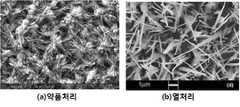
도 9는 본 발명의 일 실시예에 따른 무선 충전용 방열유닛에서 산화막을 나타낸 확대사진으로, a)는 약품처리한 경우의 사진이고, 및 b)는 열처리한 경우의 사진이다.1 is a perspective view schematically illustrating a wireless power charging module according to an embodiment of the present invention;
2 is a view showing various forms of a first example of a wireless heat-dissipating unit according to an embodiment of the present invention,
3 is a view showing various forms of a second example of a wireless heat-dissipating unit according to an embodiment of the present invention,
4 is a view showing various forms of a third example of a wireless heat-dissipating unit according to an embodiment of the present invention,
5 is a view showing various forms of a fourth example of a wireless heat-dissipating unit according to an embodiment of the present invention,
5 is a cross-sectional view of an example of a wireless heat-dissipating unit according to an embodiment of the present invention,
Fig. 7 is a sectional view of Fig. 1,
8 is a cross-sectional view showing another example of the shielding unit in Fig. 7, and Fig.
FIG. 9 is an enlarged view of an oxide film in a wireless recharging heat-radiating unit according to an embodiment of the present invention, wherein FIG. 9A is a photograph of a chemical treatment, and FIG. 9B is a photograph of a heat treatment.
이하, 첨부한 도면을 참고로 하여 본 발명의 실시예에 대하여 본 발명이 속하는 기술분야에서 통상의 지식을 가진 자가 용이하게 실시할 수 있도록 상세히 설명한다. 본 발명은 여러 가지 상이한 형태로 구현될 수 있으며 여기에서 설명하는 실시예에 한정되지 않는다. 도면에서 본 발명을 명확하게 설명하기 위해서 설명과 관계없는 부분은 생략하였으며, 명세서 전체를 통하여 동일 또는 유사한 구성요소에 대해서는 동일한 참조부호를 부가한다.Hereinafter, exemplary embodiments of the present invention will be described in detail with reference to the accompanying drawings, which will be readily apparent to those skilled in the art to which the present invention pertains. The present invention may be embodied in many different forms and is not limited to the embodiments described herein. In order to clearly illustrate the present invention, parts not related to the description are omitted, and the same reference numerals are assigned to the same or similar components throughout the specification.
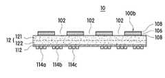
먼저, 도 1을 참조하면, 본 발명의 일 실시예에 따른 무선전력 충전모듈(10)은 안테나유닛(11), 차폐유닛(12) 및 방열유닛(100)을 포함한다.Referring to FIG. 1, a wireless
상기 안테나유닛(11)은 휴대폰, PDA, PMP, 태블릿, 멀티미디어 기기 등과 같은 휴대용 전자기기와 무선 고주파 신호를 송출하거나 수신하기 위한 것이다.The
이러한 안테나유닛(11)은 상기 차폐유닛(12)의 일면에 하나로 구비될 수도 있고, 복수 개로 구비될 수 있으며, 상기 차폐유닛(12)의 일면에 접착층을 매개로 고정된다.The
여기서, 상기 접착층은 접착 성질을 갖는 본드, PVC, 고무 또는 양면 테이프 등일 수 있으며, 전도성을 갖는 성분이 포함될 수도 있다.Here, the adhesive layer may be a bond having adhesive properties, PVC, rubber, double-sided tape or the like, and may include a conductive component.
한편, 상기 안테나유닛(11)은 시계 방향 또는 반시계 방향으로 권선되는 원형, 타원형, 나선형 또는 사각 형상과 같은 다각 형상의 평판형 코일로 구성될 수도 있고 동박 등과 같은 금속박을 에칭하여 구성될 수도 있다.Meanwhile, the
더불어, 상기 안테나유닛(11)은 회로기판(112)에 인쇄 패턴으로 형성되고 상기 회로기판(112)의 일면이 상기 차폐유닛(12)의 일면에 부착될 수도 있다.In addition, the
여기서, 상기 회로기판(112)은 그 상면에 적어도 하나의 안테나 패턴과 회로부가 형성되는 기재가 되는 요소로서, 내열성 및 내압성을 가지며, 가요성(flexible)을 갖는 소재이다. 이러한 소재의 물성을 고려할 때, 상기 회로기판(112)으로서 열경화성 고분자 필름인 폴리이미드(PI)나 PET 등과 같은 필름이 채용될 수 있다.Here, the
그리고, 상기 안테나유닛(11)은 양 단부에는 상기 회로기판(112)과 전기적인 연결을 위한 연결 단자가 인출된다.A connection terminal for electrical connection with the
이와 같은 상기 안테나유닛(11)은 송출되거나 수신되는 무선 전력 신호를 통해 전자기유도 현상에 기초한 유도 결합 방식을 이용하여 전력을 전달할 수 있도록 구비되어 수신안테나의 역할을 수행할 수도 있고 전송안테나의 역할을 수행할 수도 있다.The
이와 같은 자기유도 방식 충전기술은 공지의 기술이므로 상세한 설명은 생략하기로 한다.Such a magnetic induction charging technique is well known in the art and will not be described in detail.
이때, 상기 안테나유닛(11)은 소정의 주파수 대역에서 무선신호를 송신하거나 수신하는 적어도 하나의 안테나를 포함하며, 서로 다른 역할을 수행하는 복수 개로 구비될 수도 있다.At this time, the
일례로, 상기 안테나유닛(11)은 도 1에 도시된 바와 같이, 전력 충전, 근거리 통신 등 서로 다른 주파수 대역에서 각각의 역할을 수행하는 WPT(Wireless Power Transfer)용 안테나(114c) 및 NFC(Near Field Communication)용 안테나(114a)가 포함될 수 있다.1, the
여기서, 상기 NFC용 안테나(114a)는 WPT용 안테나(114c) 보다 주파수 대역이 높기 때문에 회로기판(112)의 외곽을 따라 미세한 선폭의 직사각형 형태로 도전성 패턴으로 형성되고, WPT용 안테나(114c)는 전력 전송이 요구되며 NFC용 안테나(114a)보다 낮은 주파수 대역을 사용하므로 NFC용 안테나(114a)의 내측에 NFC용 안테나(114a)의 선폭보다 넓은 선폭으로 형성될 수 있다.Since the
더불어, 상기 안테나유닛(11)은 MST(Magnetic Secure Transmission)용 안테나(114b)가 추가로 포함될 수 있다.In addition, the
상기 차폐유닛(12)은 일정 면적을 갖는 판상의 부재로 이루어지며, 상기 안테나유닛(11)에서 발생되는 자기장을 차폐하여 외부 누출을 방지함과 아울러 소정의 방향으로 집속시켜 해당 안테나의 특성을 향상시키는 역할을 수행한다.The shielding
이를 위해, 차폐유닛(12)은 박판의 자성 시트가 단층으로 이루어질 수도 있고, 복수 개의 자성 시트가 적층되는 형태로 구비될 수도 있다.To this end, the shielding
즉, 상기 차폐유닛(12)은 도 7에 도시된 바와 같이 서로 다른 투자율을 갖는 제1시트층(121) 및 제2시트층(122)으로 구비될 수 있고, 상기 제1시트층(121)은 상기 제2시트층(122)보다 상대적으로 높은 투자율을 갖는 재질로 이루어질 수 있다. 또한, 상기 차폐유닛(12)은 상기 제1시트층(121) 및 상기 제2시트층(122) 중 어느 하나의 단층으로 이루어질 수도 있다.7, the shielding
여기서, 상대적으로 높은 투자율을 갖는 제1시트층(121)은 WPT용 안테나(114c)의 특성을 향상시키기 위한 것이며, 상대적으로 낮은 투자율을 갖는 제2시트층(122)은 NFC용 안테나(114a)의 특성을 향상시키기 위한 것이다.Here, the
이때, 상기 제1시트층(121)은 비정질 합금의 리본시트 또는 나노 결정립 합금의 리본시트가 사용될 수 있고, 상기 제2시트층(122)은 페라이트 시트가 사용될 수 있다.At this time, the
여기서, 상기 비정질 합금 또는 나노 결정립 합금은 Fe계 또는 Co계 자성 합금이 사용될 수 있으며, 재료 비용을 고려할 때 Fe계 자성 합금을 사용하는 것이 바람직하다. 더불어, 상기 비정질 합금 및 나노 결정립 합금은 3원소 합금 또는 5원소 합금을 포함할 수 있고, 예를 들어, 상기 3원소 합금은 Fe, Si 및 B를 포함하며, 상기 5원소 합금은 Fe, Si, B, Cu 및 Nb를 포함할 수 있다.Here, the amorphous alloy or the nano-crystal alloy may be an Fe-based or a Co-based magnetic alloy, and it is preferable to use an Fe-based magnetic alloy in consideration of material cost. In addition, the amorphous alloy and the nanocrystalline alloy may include a three-element alloy or a five-element alloy. For example, the three-element alloy may include Fe, Si, and B, B, Cu and Nb.
그리고, 상기 페라이트 시트는 소결 페라이트 시트로 이루어질 수 있으며, MnZn 페라이트 또는 NiZn 페라이트로 이루어질 수 있다. 바람직하게는 상기 페라이트 시트가 NiZn 소결 페라이트로 이루어질 수 있다.The ferrite sheet may be a sintered ferrite sheet, and may be composed of MnZn ferrite or NiZn ferrite. Preferably, the ferrite sheet may be made of NiZn sintered ferrite.
한편, 상기 제1시트층(121)은 도 8에 도시된 바와 같이 2층 이상의 복수 개의 리본시트 층으로 구성될 수도 있음을 밝혀둔다.Meanwhile, it is noted that the
더불어, 상기 제1시트층(121) 및 제2시트층(122)을 위에 언급한 종류로 한정하는 것은 아니며 자성의 성질을 갖는 물질이면 모두 사용될 수 있음을 밝혀둔다.In addition, it should be noted that the
이때, 상기 제1시트층(121) 및 제2시트층(122) 중 적어도 어느 하나는 와전류의 발생을 억제할 수 있도록 복수 개의 미세 조각으로 분리 형성될 수 있으며, 복수 개의 미세 조각들은 서로 이웃하는 미세 조각들 간에 전체적으로 절연되거나 부분적으로 절연되도록 구비될 수 있다.At this time, at least one of the
이때, 상기 복수 개의 미세 조각은 1㎛ ~ 3mm의 크기로 구비될 수 있으며, 각각의 조각들은 비정형으로 랜덤하게 이루어질 수 있다.At this time, the plurality of fine pieces may be formed to have a size of 1 to 3 mm, and each piece may be irregularly randomized.
그리고, 상기 차폐유닛(12')이 상기 제1시트층(121)만으로 이루어지고, 상기제1시트층(121)이 복수 개의 시트층으로 적층되고 각각의 시트층이 미세조각으로 분리 형성되는 경우 각각의 시트층 사이에는 비전도성 재질로 이루어진 접착층(121d)이 배치되어 서로 적층되는 한 쌍의 시트층 사이에 스며들 수 있도록 할 수도 있다. 이로 인해, 상기 한 쌍의 시트층 사이에 배치되는 접착층(121d)은 각각의 시트층을 구성하는 복수 개의 미세 조각을 절연하는 역할을 수행할 수도 있다.When the shielding unit 12 'comprises only the
여기서, 상기 접착층은 접착제로 구비될 수도 있으며 필름 형태의 기재의 일면 또는 양면에 접착제가 도포된 형태로 구비될 수도 있다.Here, the adhesive layer may be formed of an adhesive or may be provided on one side or both sides of a substrate in the form of a film with an adhesive applied thereto.
상기 방열유닛(100)은 상기 차폐유닛(12)의 일면에 배치되어 무선 충전시 상기 안테나유닛(11)으로부터 발생되는 열을 상기 차폐유닛(12)을 통해 전달받아 외부로 방출함으로써 무선전력 충전모듈(10)의 충전효율을 높일 수 있도록 한다.The heat dissipation unit 100 is disposed on one side of the shielding
이러한 방열유닛(100)은 상기 차폐유닛(12)과 대략 동일한 면적을 갖도록 구비되어 상기 차폐유닛(12)의 일면에 전체적으로 구비될 수도 있다. 더불어, 상기 방열유닛(100)은 상기 차폐유닛(12)보다 상대적으로 작은 면적을 갖도록 구비되어 상기 차폐유닛(12)의 일면에 부분적으로 구비될 수도 있고, 복수 개로 구비되어 소정의 간격을 두고 상기 차폐유닛(12)의 일면에 배치될 수도 있음을 밝혀둔다.The heat-dissipating unit 100 may have a substantially same area as that of the shielding
이때, 상기 방열유닛(100)은 열원과의 접촉면적을 넓혀 상기 열원에서 발생된 열을 빠르게 전달받을 수 있도록 일정면적을 갖는 판상의 기재층으로 이루어질 수 있다.At this time, the heat dissipation unit 100 may be formed of a plate-like base layer having a predetermined area so that the heat generated from the heat source can be quickly transmitted by widening the contact area with the heat source.
여기서, 상기 기재층은 열전도성이 우수한 재질로 이루어진다. 일례로, 상기 기재층은 Cu, Al, 그라파이트 중 어느 하나 또는 그 조합으로 이루어질 수 있다. 또한, 상기 기재층은 위에 열거한 것에 한정하지 않고 열전도도가 200W/m·K이상인 금속재질로 이루어질 수 있다.Here, the base layer is made of a material having excellent thermal conductivity. For example, the substrate layer may be made of any one of Cu, Al, graphite, or a combination thereof. The base layer is not limited to those listed above, and may be made of a metal material having a thermal conductivity of 200 W / m · K or more.
이때, 상기 방열유닛(100)은 기재층 상에서 와전류의 발생을 억제하여 무선 충전 효율을 향상시키면서도 방열효과를 향상시킬 수 있도록 한다.At this time, the heat dissipation unit 100 can suppress the generation of an eddy current on the base layer, thereby improving the wireless charging efficiency and improving the heat dissipation effect.
이를 위해, 상기 방열유닛(100)은 기재층에 일정길이를 갖는 적어도 하나의 슬롯이 형성될 수 있다. 여기서, 상기 슬롯(102)은 무선 충전용 안테나 패턴에 대응하는 위치에 형성될 수 있다. 이와 같이, 상기 슬롯(102)에 의해 무선충전시 와전류의 발생을 억제하여 충전효율을 높일 수 있다.To this end, the heat dissipation unit 100 may have at least one slot having a predetermined length in the substrate layer. Here, the
일례로, 상기 슬롯(102)은 도 2b에 도시된 바와 같이, 기재층에서 무선 충전용 안테나 패턴(200)과 직교하는 방향으로 적어도 하나의 슬롯(102)이 형성될 수 있다. 이때, 상기 슬롯(102)은 상기 기재층을 관통하여 형성될 수 있다.As an example, the
이와 같이, 상기 슬롯(102)이 상기 무선 충전용 안테나 패턴(200)과 직교하는 방향으로 형성됨으로써, 와전류의 손실을 억제하는 기능을 강화시켜 충전효율을 더욱 향상시킬 수 있다.As described above, since the
이때, 상기 슬롯(102)은 방열유닛(100)의 기재층에서 임의의 위치에 적어도 하나가 형성되기만 하여도 와전류의 발생을 억제할 수 있기 때문에 다양한 형태로 구성될 수 있다.At this time, since at least one of the
도 2a에 도시된 바와 같이, 상기 방열유닛(100a)은 상기 기재층의 어느 하나의 변까지 연장하여 상기 슬롯(102)이 형성될 수 있다. 이때, 상기 슬롯(102)은 임의의 위치에 랜덤하게 형성될 수 있다. 예를 들면, 상기 슬롯(102)은 상기 기재층의 4개의 변 중 적어도 하나에 대응하는 위치에 형성될 수 있다. 또한, 상기 슬롯(102)은 모서리 중 어느 하나에 대응하는 위치에 형성될 수 있다.As shown in FIG. 2A, the
도 2a에는 상기 슬롯(102)이 상기 기재층의 어느 하나의 변에 대하여 수직으로 형성되고, 모서리에 대하여 대략 45도 정도로 형성되는 것으로 도시되고 설명되었으나, 이에 한정되지 않고, 상기 기재층의 어느 하나의 변 또는 모서리에 대하여 임의의 각도로 형성될 수 있다.2A, the
도 2b에 도시된 바와 같이, 방열유닛(100b)은 무선 충전용 안테나 패턴(200)과 직교하는 방향으로 형성될 수 있다.As shown in FIG. 2B, the
이때, 상기 무선 충전용 안테나 패턴(200)이 직선을 이루는 영역(예를 들면, 도 2b에서 상기 방열유닛(100b)의 변과 평행한 영역)에서는 상기 무선 충전용 안테나 패턴(200)의 길이방향에 대하여 수직한 방향으로 형성될 수 있다.At this time, in the region where the
또한, 상기 무선 충전용 안테나 패턴(200)이 곡선을 이루는 영역(예를 들면, 도 2b에서 상기 방열유닛(100b)의 모서리 부근 영역)에서는 상기 무선 충전용 안테나 패턴(200)의 접선에 대하여 수직한 방향으로 형성될 수 있다.2B). In the area where the
도 2c에 도시된 바와 같이, 방열유닛(100c)은 특정 위치에만 집중적으로 상기 슬롯(102)이 형성될 수 있다.As shown in FIG. 2C, the
예를 들면, AP(Application processor) 등과 같이 많은 열을 발생시키는 부품(300)에 대응하는 영역, 특히, 상기 부품(300)의 직하부 또는 직상부에서 방열특성을 향상시키기 위해 상기 슬롯(102)을 형성하지 않고, 그 주변 또는 반대측에만 상기 슬롯(102)이 형성될 수 있다. 즉, 상기 슬롯(102)은 기재층에 의한 열확산을 저해하기 때문에 고발열 부품(300)에 대응하는 영역에는 형성되지 않음으로써 방열 특성을 더욱 향상시킬 수 있다.For example, an area corresponding to a
도 3a 및 도 3b에 도시된 바와 같이, 방열유닛(100d,100e)은 상기 기재층의 어느 하나의 변까지 연장하지 않고 상기 기재층의 중앙에 부분적으로 슬롯(102a)이 형성될 수 있다. 여기서, 상기 슬롯(102a)은 와전류의 억제를 위해서 사용되면서, 열확산을 위한 방열면적을 증가시키기 위해 상기 기재층 상에서 중앙에만 부분적으로 형성될 수 있다.As shown in Figs. 3A and 3B, the
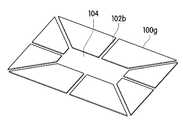
한편, 상기 기재층은 다른 부품의 배치 또는 연결 등을 고려하여 중앙에 관통구(104)가 형성될 수 있다. 이때, 도 4a 및 도 4b에 도시된 바와 같이, 방열유닛(100f,100g)은 상기 관통구(104)로부터 상기 기재층의 어느 하나의 변까지 슬롯(102b)이 연장하여 형성될 수 있다.Meanwhile, the through
이와 같이 중앙에 상기 관통구(104)가 형성된 상기 기재층에 형성되는 슬롯(102b,102c,102d,102e)은 그 위치에 따라 다양하게 설계될 수 있다.The
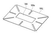
예를 들면, 도 5a에 도시된 바와 같이, 방열유닛(100h)은 슬롯(102c)이 상기 관통구(104) 또는 상기 기재층의 어느 하나의 변과 연결되지 않고 상기 기재층의 중앙에 부분적으로 형성될 수 있다.For example, as shown in Fig. 5A, the
도 5b에 도시된 바와 같이, 방열유닛(100i)은 슬롯(102d)이 상기 기재층의 어느 하나의 변과 연결되지 않고 상기 관통구(104)로만 연장하여 형성될 수 있다.As shown in FIG. 5B, the
도 5c에 도시된 바와 같이, 방열유닛(100j)은 슬롯(102e)이 상기 관통구(104)와 연결되지 않고, 상기 기재층의 어느 하나의 변으로만 연장하여 형성될 수 있다.As shown in FIG. 5C, the
여기서, 상기 방열유닛(100i,100j)은 기재층이 슬롯에 의해 개별 조각으로 분리되지 않고 일체로 이루어지므로, 도 4b에 도시된 방열유닛(100g)에 비하여 작업성이 우수하여 대량 생산이 용이할 수 있다.Here, the
더불어, 도면에 도시하지는 않았지만, 상기 방열유닛(100)의 방열효과를 더욱 향상시키기 위해 상기 방열유닛(100)은 상기 기재층의 상부면과 하부면 중 적어도 일면에 형성된 열전도 접착제를 더 포함할 수 있다.In addition, although not shown in the drawings, the heat dissipating unit 100 may further include a heat conductive adhesive formed on at least one of the upper surface and the lower surface of the substrate layer to further improve the heat dissipating effect of the heat dissipating unit 100 have.
또한, 상기 방열유닛(100k)은 전체적인 두께를 줄이면서도 방사율을 높여 방열효과를 높이고, 저항값을 높여 와전류의 발생을 억제함으로써 충전 효율을 높일 수 있도록 할 수 있다.In addition, the
이를 위해, 상기 방열유닛(100k)은 도 6에 도시된 바와 같이, 기재층(106)과, 상기 기재층(106)의 상부면과 하부면 중 적어도 일면에 구비되는 산화막(108)을 포함할 수 있다. 바람직하게는 상기 산화막(108)은 상기 기재층(106)의 상부면과 하부면 모두에 구비될 수 있다.6, the
여기서, 상기 기재층(106)을 구성하는 금속 재질은 열전도성이 우수한 재질이 사용될 수 있으며, 바람직하게는 Cu, Al, 및 그라파이트 중 어느 하나 또는 그 조합으로 이루어질 수 있다.Here, the metal material constituting the
이때, 본 발명에 따른 방열유닛(100k)은 흑화 처리를 통해 상기 방열유닛(100k)을 구성하는 금속층의 표면을 산화시켜 CuO 및 Cu2O와 같은 산화막을 형성시킨다.In this case, the heat radiating unit (100k) according to the present invention by oxidizing the surface of the metal layer constituting the heat radiating unit (100k) through the reducing treatment to form an oxide such as CuO and Cu2 O.
이를 통해, 부식을 막아 갈라짐을 최소화하고 표면적 증가에 따른 밀착력 및 접착력을 향상시키며 재료 자체의 방사율을 높여 전체적인 두께를 증가시키지 않으면서도 방열특성을 높여줄 수 있게 된다.As a result, it is possible to minimize cracking by preventing corrosion and improve the adhesion and adhesion according to the increase of the surface area and increase the emissivity of the material itself, thereby enhancing the heat radiation characteristic without increasing the overall thickness.
더불어, 상기 금속층의 표면에 형성된 산화막(108)이 절연층의 역할을 수행하여 전체적인 저항값을 높여 줌으로써 와전류의 발생을 줄여 충전효율 역시 높여주게 된다. 이를 통해, 와전류의 발생을 줄이기 위하여 저항값을 높이기 위해 별도의 부재를 적층할 필요가 없어 전체적인 두께를 증가시키지 않으면서도 무선충전 방식에서 요구하는 방열특성을 구현할 수 있게 된다.In addition, the
여기서, 상기 흑화 처리는 약품을 이용할 수도 있고, 열처리를 통하여 수행될 수도 있으며, 플라즈마 처리를 통해 수행될 수도 있다.Here, the blackening treatment may be performed using chemicals, heat treatment, or plasma treatment.
상술한 본 발명의 일실시예에 따른 무선충전용 방열유닛(100) 및 이를 포함하는 무선전력 충전모듈(10)은 Qi 방식에 적용될 수도 있고, 차폐유닛(12)과 안테나유닛(11) 사이에 자기력선을 유도하는 별도의 어트랙터(미도시)가 구비되어 PMA 방식의 무선충전에 적용될 수도 있음을 밝혀둔다. 더불어, 상기 무선전력 충전모듈(10)이 수신모듈로 사용되는 경우 휴대단말기와 같은 전자기기의 백커버에 부착되는 형태로 구비될 수도 있음을 밝혀둔다.The wireless heat dissipating unit 100 and the wireless
이상에서 본 발명의 일 실시예에 대하여 설명하였으나, 본 발명의 사상은 본 명세서에 제시되는 실시 예에 제한되지 아니하며, 본 발명의 사상을 이해하는 당업자는 동일한 사상의 범위 내에서, 구성요소의 부가, 변경, 삭제, 추가 등에 의해서 다른 실시 예를 용이하게 제안할 수 있을 것이나, 이 또한 본 발명의 사상범위 내에 든다고 할 것이다.While the present invention has been particularly shown and described with reference to exemplary embodiments thereof, it is to be understood that the invention is not limited to the disclosed exemplary embodiments, It will be understood by those skilled in the art that various changes in form and details may be made therein without departing from the spirit and scope of the invention as defined by the appended claims.
10 : 무선전력 충전모듈11 : 안테나유닛
12 : 차폐유닛
100,100a,100b,100c,100d,100e,100f,100h,100i,100j,100k : 방열유닛
102,102a,102b,102c,102d,102e : 슬롯
104 : 관통구106 : 기재층
108 : 산화막112 : 회로기판
114a : NFC용 안테나114b : MST용 안테나
114c : WPT용 안테나
121,121a,121b,121c : 제1시트층121d : 접착층
122 : 제2시트층124 : 보호필름
200 : 무선 충전용 안테나 패턴300 : 발열 부품10: Wireless power charging module 11: Antenna unit
12: Shielding unit
100, 100a, 100b, 100c, 100d, 100e, 100f, 100h, 100i, 100j,
102, 102a, 102b, 102c, 102d, 102e:
104: through hole 106: substrate layer
108: oxide film 112: circuit board
114a: Antenna for
114c: Antenna for WPT
121, 121a, 121b, 121c:
122: second sheet layer 124: protective film
200: Wireless charging antenna pattern 300: Heat generating component
Claims (26)
Translated fromKorean상기 적어도 하나의 슬롯은 무선 충전용 안테나의 패턴과 교차되게 형성되되, 방열특성을 향상시키기 위해 AP(Application Processor)와 대응하는 영역을 회피하여 형성되는 무선 충전용 방열유닛.And at least one slot having a predetermined length and formed of a plate-shaped base layer having a predetermined area for discharging heat generated during wireless charging to the outside,
Wherein the at least one slot is formed so as to intersect a pattern of a wireless charging antenna and is formed by avoiding a region corresponding to an AP (Application Processor) in order to improve heat dissipation characteristics.
상기 슬롯은 상기 무선 충전용 안테나의 패턴과 직교하는 방향으로 형성되는 무선 충전용 방열유닛.The method according to claim 1,
Wherein the slot is formed in a direction orthogonal to the pattern of the wireless rechargeable antenna.
상기 슬롯은 상기 기재층을 관통하여 형성되는 무선 충전용 방열유닛.The method according to claim 1,
Wherein the slot is formed through the substrate layer.
상기 슬롯은 상기 기재층의 어느 하나의 변까지 연장 형성되는 무선 충전용 방열유닛.5. The method of claim 4,
Wherein the slot extends to any one side of the substrate layer.
상기 기재층은 중앙에 관통구가 형성되며,
상기 슬롯은 상기 관통구로부터 상기 기재층의 어느 하나의 변까지 연장 형성되는 무선 충전용 방열유닛.The method according to claim 1,
The base layer has a through hole at the center thereof,
Wherein the slot extends from the through-hole to either one side of the substrate layer.
상기 기재층은 중앙에 관통구가 형성되며,
상기 슬롯은 상기 관통구로 연장 형성되는 무선 충전용 방열유닛.The method according to claim 1,
The base layer has a through hole at the center thereof,
And the slot extends to the through-hole.
상기 슬롯은 상기 기재층의 어느 하나의 변까지 연장 형성되는 무선 충전용 방열유닛.The method according to claim 1,
Wherein the slot extends to any one side of the substrate layer.
상기 기재층은 Cu, Al, 및 그라파이트 중 어느 하나 또는 그의 조합으로 이루어지는 무선 충전용 방열유닛.The method according to claim 1,
Wherein the base layer is formed of any one of Cu, Al, and graphite or a combination thereof.
상기 기재층의 상부면과 하부면 중 적어도 일면에 형성된 열전도 접착제를 더 포함하는 무선 충전용 방열유닛.The method according to claim 1,
And a heat conductive adhesive formed on at least one of the upper surface and the lower surface of the base layer.
상기 기재층의 상부면과 하부면 중 적어도 일면에 형성된 산화막을 더 포함하는 무선 충전용 방열유닛.The method according to claim 1,
Further comprising an oxide film formed on at least one of an upper surface and a lower surface of the substrate layer.
상기 안테나유닛의 일면에 배치되어 자기장을 유기하는 차폐유닛; 및
상기 차폐유닛의 일면에 배치되어 열을 방출하며 일정면적을 갖는 판상의 기재층으로 이루어진 청구항 제1항, 제3항 내지 제5항, 및 제7항 내지 제12항 중 어느 한 항에 기재된 방열유닛;을 포함하는 무선전력 충전모듈.At least one antenna unit;
A shielding unit disposed on one surface of the antenna unit to induce a magnetic field; And
The heat dissipation device according to any one of claims 1 to 7, wherein the heat dissipation plate is made of a plate-like base material layer disposed on one surface of the shielding unit and emitting heat, A wireless power charging module.
상기 안테나유닛은 무선 충전용 안테나 및 NFC용 안테나를 포함하는 무선전력 충전모듈.14. The method of claim 13,
Wherein the antenna unit comprises a wireless charging antenna and an NFC antenna.
상기 안테나유닛은 MST용 안테나를 더 포함하는 무선전력 충전모듈.15. The method of claim 14,
Wherein the antenna unit further comprises an antenna for an MST.
상기 차폐유닛은 무선 충전용 안테나의 특성을 향상시키는 제1시트층과, NFC용 안테나의 특성을 향상시키는 제2시트층을 포함하는 무선전력 충전모듈.15. The method of claim 14,
Wherein the shielding unit comprises a first sheet layer for improving the characteristics of the wireless recharging antenna and a second sheet layer for improving the characteristics of the NFC antenna.
상기 제1시트층은 상기 제2시트층보다 상대적으로 높은 투자율을 갖는 재질로 이루어지는 무선전력 충전모듈.17. The method of claim 16,
Wherein the first sheet layer is made of a material having a relatively higher permeability than the second sheet layer.
상기 제1시트층은 비정질 합금의 리본시트 또는 나노 결정립 합금의 리본시트이고, 상기 제2시트층은 페라이트 시트인 무선전력 충전모듈.17. The method of claim 16,
Wherein the first sheet layer is a ribbon sheet of an amorphous alloy or a ribbon sheet of a nanocrystalline alloy, and the second sheet layer is a ferrite sheet.
상기 제1시트층은 비정질 합금의 리본시트 또는 나노 결정립 합금의 리본시트가 복수층으로 적층되는 무선전력 충전모듈.17. The method of claim 16,
Wherein the first sheet layer is formed by laminating a ribbon sheet of an amorphous alloy or a ribbon sheet of a nano-crystal alloy into a plurality of layers.
상기 페라이트 시트는 MnZn 페라이트 또는 NiZn 페라이트로 이루어진 무선전력 충전모듈.19. The method of claim 18,
Wherein the ferrite sheet is made of MnZn ferrite or NiZn ferrite.
상기 제1시트층 및 제2시트층 중 적어도 하나는 복수 개의 미세 조각으로 분리 형성되는 무선전력 충전모듈.17. The method of claim 16,
Wherein at least one of the first sheet layer and the second sheet layer is separated into a plurality of micro pieces.
상기 복수 개의 미세 조각들은 서로 이웃하는 미세 조각들 간에 전체적으로 절연되거나 부분적으로 절연되는 무선전력 충전모듈.22. The method of claim 21,
Wherein the plurality of microparts are totally insulated or partially insulated between neighboring microparts.
상기 복수 개의 미세 조각은 1㎛ ~ 3mm의 크기인 무선전력 충전모듈.22. The method of claim 21,
Wherein the plurality of microparts have a size of 1 [mu] m to 3 mm.
상기 복수 개의 미세 조각은 비정형으로 이루어지는 무선전력 충전모듈.22. The method of claim 21,
Wherein the plurality of micro-pieces are atypical.
일정 이상의 열전도도를 갖는 금속 박막 시트를 포함하고,
상기 금속 박막 시트는 일면 또는 양면에 표면의 고저항 특성 및 방사율 개선을 위하여 형성된 산화막층을 포함하며
상기 금속 박막 시트는 일정길이를 갖는 적어도 하나의 슬롯을 포함하며,
상기 적어도 하나의 슬롯은 무선 충전용 안테나의 패턴과 교차되게 형성되되, 방열특성을 향상시키기 위해 AP(Application Processor)와 대응하는 영역을 회피하여 형성되는 무선충전용 방열유닛.A heat dissipation unit installed in a shielding unit of a wireless power charging module for dissipating heat generated from a heat source,
And a metal thin film sheet having a thermal conductivity higher than a predetermined value,
The metal thin film sheet includes an oxide film layer formed on one surface or both surfaces for improving the surface resistance and emissivity of the surface
Wherein the metal foil sheet includes at least one slot having a predetermined length,
Wherein the at least one slot is formed so as to intersect a pattern of a wireless charging antenna and is formed by avoiding a region corresponding to an AP (Application Processor) in order to improve heat dissipation characteristics.
상기 금속 박막 시트는 동박인 무선 충전용 방열유닛.26. The method of claim 25,
Wherein the metal foil sheet is a copper foil.
Priority Applications (3)
| Application Number | Priority Date | Filing Date | Title |
|---|---|---|---|
| CN201680018421.4ACN107371387B (en) | 2015-04-02 | 2016-03-22 | Heat dissipation unit for wireless charging and wireless power charging module including the same |
| PCT/KR2016/002843WO2016159551A1 (en) | 2015-04-02 | 2016-03-22 | Heat dissipation unit for wireless charging and wireless power charging module comprising same |
| US15/563,935US10334752B2 (en) | 2015-04-02 | 2016-03-22 | Heat dissipation unit for wireless charging and wireless power charging module comprising same |
Applications Claiming Priority (2)
| Application Number | Priority Date | Filing Date | Title |
|---|---|---|---|
| KR1020150046965 | 2015-04-02 | ||
| KR20150046965 | 2015-04-02 |
Related Child Applications (1)
| Application Number | Title | Priority Date | Filing Date |
|---|---|---|---|
| KR1020150156001ADivisionKR20160118911A (en) | 2015-04-02 | 2015-11-06 | Heat radiation unit for a wireless charging and wireless charging module having the same |
Publications (1)
| Publication Number | Publication Date |
|---|---|
| KR101629653B1true KR101629653B1 (en) | 2016-06-13 |
Family
ID=56191419
Family Applications (2)
| Application Number | Title | Priority Date | Filing Date |
|---|---|---|---|
| KR1020150110180AActiveKR101629653B1 (en) | 2015-04-02 | 2015-08-04 | Heat radiation unit for a wireless charging and wireless charging module having the same |
| KR1020150156001AWithdrawnKR20160118911A (en) | 2015-04-02 | 2015-11-06 | Heat radiation unit for a wireless charging and wireless charging module having the same |
Family Applications After (1)
| Application Number | Title | Priority Date | Filing Date |
|---|---|---|---|
| KR1020150156001AWithdrawnKR20160118911A (en) | 2015-04-02 | 2015-11-06 | Heat radiation unit for a wireless charging and wireless charging module having the same |
Country Status (4)
| Country | Link |
|---|---|
| US (1) | US10334752B2 (en) |
| KR (2) | KR101629653B1 (en) |
| CN (1) | CN107371387B (en) |
| WO (1) | WO2016159551A1 (en) |
Cited By (4)
| Publication number | Priority date | Publication date | Assignee | Title |
|---|---|---|---|---|
| CN107732408A (en)* | 2017-07-10 | 2018-02-23 | 深圳市嘉姆特通信电子有限公司 | Radio antenna structure with heat sinking function |
| WO2019124755A1 (en)* | 2017-12-20 | 2019-06-27 | 엘지이노텍 주식회사 | Wireless charging apparatus provided with wireless communication coil |
| WO2022092709A1 (en)* | 2020-10-28 | 2022-05-05 | 주식회사 아모센스 | Magnetic shielding sheet for antenna module and antenna module comprising same |
| KR20250036354A (en) | 2023-09-07 | 2025-03-14 | 동국대학교 산학협력단 | Wireless charging device and system |
Families Citing this family (39)
| Publication number | Priority date | Publication date | Assignee | Title |
|---|---|---|---|---|
| US10177441B2 (en)* | 2015-10-15 | 2019-01-08 | Asustek Computer Inc. | Antenna module |
| KR102548981B1 (en)* | 2016-11-04 | 2023-06-28 | 한국전기연구원 | Apparatus for receiving wireless power |
| KR101891600B1 (en) | 2017-02-03 | 2018-08-24 | 엘지전자 주식회사 | Wireless charger for mobile terminal in vehicle and vehicle |
| KR20180114721A (en)* | 2017-04-11 | 2018-10-19 | 엘지이노텍 주식회사 | A wireless power module |
| KR102335846B1 (en)* | 2017-04-17 | 2021-12-07 | 삼성전자주식회사 | Electronic device comprising a plurality of coils |
| KR102136216B1 (en)* | 2017-06-16 | 2020-07-21 | 주식회사 아모센스 | wireless power transmission device for car |
| KR20190006344A (en)* | 2017-07-10 | 2019-01-18 | 송영석 | Structure of radiant heat wireless communications antenna |
| KR102119591B1 (en) | 2017-09-14 | 2020-06-05 | 주식회사 아모센스 | wireless power transmission device |
| KR20190061617A (en)* | 2017-11-28 | 2019-06-05 | 엘지이노텍 주식회사 | Wireless charger having wireless communication coil |
| CN108761365B (en)* | 2018-04-11 | 2021-02-19 | 上海联影医疗科技股份有限公司 | Shielding shell, manufacturing method of shielding shell, PET detector and system |
| KR102126773B1 (en)* | 2018-05-15 | 2020-06-25 | 주식회사 위츠 | Heat radiating sheet for wireless charging and electronic device having the same |
| FR3082370B1 (en)* | 2018-06-12 | 2020-05-15 | Continental Automotive France | HIGH FREQUENCY NEAR FIELD COMMUNICATION AND INDUCTION RECHARGING DEVICE |
| DE212019000278U1 (en)* | 2018-07-20 | 2020-12-21 | Murata Manufacturing Co., Ltd. | Wireless communication device |
| US11449106B1 (en) | 2018-07-31 | 2022-09-20 | Corning Incorporated | Metallic back cover, such as for phones and tablets |
| KR20200018001A (en)* | 2018-08-10 | 2020-02-19 | 주식회사 위츠 | Coil moudule |
| US11452240B2 (en) | 2018-08-30 | 2022-09-20 | Dai Nippon Printing Co., Ltd | Power transfer apparatus, power transmission apparatus, power reception apparatus, and power transfer system |
| CN113348591B (en)* | 2018-10-30 | 2024-10-22 | 株式会社Kmw | Antenna device |
| KR102603301B1 (en)* | 2018-12-20 | 2023-11-17 | 주식회사 아모그린텍 | Heat radiation structure and heat induction apparatus |
| EP3671561A1 (en)* | 2018-12-21 | 2020-06-24 | Thales Dis France SA | Method for manufacturing a metal radiofrequency smart card with improved electromagnetic permittivity |
| EP3671562A1 (en) | 2018-12-21 | 2020-06-24 | Thales Dis France SA | Method for manufacturing a metal radiofrequency smart card with improved permittivity with extended perforations |
| CN112103642B (en)* | 2019-06-18 | 2021-11-09 | 阿莫先恩电子电器有限公司 | Magnetic field shielding sheet, method for manufacturing same, wireless power receiving module, and terminal device |
| CN211556140U (en)* | 2019-06-18 | 2020-09-22 | 阿莫先恩电子电器有限公司 | Magnetic field shielding sheet, wireless power receiving module and portable terminal device thereof |
| CN211556142U (en)* | 2019-07-22 | 2020-09-22 | 阿莫先恩电子电器有限公司 | Magnetic field shielding sheet, wireless power receiving module and portable terminal device thereof |
| WO2021015550A1 (en) | 2019-07-22 | 2021-01-28 | 주식회사 아모센스 | Magnetic field shielding sheet |
| WO2021071212A1 (en)* | 2019-10-07 | 2021-04-15 | 에스케이씨 주식회사 | Wireless charging device and mobile means including same |
| WO2021108473A1 (en)* | 2019-11-29 | 2021-06-03 | Laird Technologies, Inc. | Heat spreaders for wireless charging |
| CN112888240A (en)* | 2019-11-29 | 2021-06-01 | 莱尔德技术股份有限公司 | Heat sink and device comprising same |
| WO2021114076A1 (en)* | 2019-12-10 | 2021-06-17 | 瑞声声学科技(深圳)有限公司 | Wireless charging module |
| FR3105856B1 (en)* | 2019-12-31 | 2022-05-06 | Idemia France | Metal smart card suitable for contactless operation |
| US11310946B2 (en) | 2020-02-11 | 2022-04-19 | Toyota Motor Engineering & Manufacturing North America, Inc. | Automotive wireless charger with self temperature management |
| US11540423B2 (en) | 2020-02-21 | 2022-12-27 | Toyota Motor Engineering & Maufacturing North American, Inc. | Wireless charging pad with evaporative cooling |
| US11329497B2 (en) | 2020-03-02 | 2022-05-10 | Toyota Motor Engineering & Manufacturing North America, Inc. | Wireless charger with retention and cooling |
| DE102020112356A1 (en) | 2020-05-07 | 2021-11-11 | Industrieanlagen- Betriebsgesellschaft mit beschränkter Haftung | Magnetic shielding device, in particular to avoid excessive heating of foreign bodies, use and arrangement of such a device for devices for inductive energy transmission and a coil device with such a device |
| US11474571B2 (en)* | 2020-05-19 | 2022-10-18 | Samsung Electronics Co., Ltd. | Display panel module and electronic device including multiple display panel modules |
| KR102312981B1 (en) | 2020-10-22 | 2021-10-15 | 더가우스 주식회사 | Wireless power reception apparatus and a method of manufacturing the same |
| KR102220061B1 (en)* | 2020-11-23 | 2021-02-25 | 주식회사 이엠따블유 | Antenna module using one-sided pattern |
| JP7452475B2 (en)* | 2021-03-10 | 2024-03-19 | 株式会社デンソー | coil unit |
| KR102577093B1 (en)* | 2021-06-01 | 2023-09-08 | 에스케이씨 주식회사 | Wireless Charging Apparatus and Electric Vehicle having the same |
| CN119789393B (en)* | 2025-03-07 | 2025-05-30 | 深圳市贝兰德科技有限公司 | High-heat-dissipation safe detachable wireless charging receiving end control chip architecture |
Citations (5)
| Publication number | Priority date | Publication date | Assignee | Title |
|---|---|---|---|---|
| KR20120029433A (en)* | 2009-05-20 | 2012-03-26 | 코닌클리케 필립스 일렉트로닉스 엔.브이. | Electronic device having an inductive receiver coil with ultra-thin shielding layer and method |
| JP2014011852A (en)* | 2012-06-28 | 2014-01-20 | Panasonic Corp | Portable terminal |
| KR20140101665A (en)* | 2012-01-09 | 2014-08-20 | 주식회사 케이더파워 | The reciving set for the wireless charging system |
| KR20140111799A (en)* | 2013-03-12 | 2014-09-22 | 삼성전기주식회사 | Coil substrate for cordless charging and electric device using the same |
| KR20150026670A (en) | 2013-08-30 | 2015-03-11 | 주식회사 서환이지 | Heat dissipation sheet using graphite for electronic device |
Family Cites Families (6)
| Publication number | Priority date | Publication date | Assignee | Title |
|---|---|---|---|---|
| GB2431823B (en)* | 2005-10-27 | 2010-12-15 | Hewlett Packard Development Co | Inductively powered transponder device |
| US20110050164A1 (en)* | 2008-05-07 | 2011-03-03 | Afshin Partovi | System and methods for inductive charging, and improvements and uses thereof |
| US9252611B2 (en) | 2011-12-21 | 2016-02-02 | Amosense Co., Ltd. | Magnetic field shielding sheet for a wireless charger, method for manufacturing same, and receiving apparatus for a wireless charger using the sheet |
| US20150269477A1 (en)* | 2012-08-30 | 2015-09-24 | David Finn | Dual-interface hybrid metal smartcard with a booster antenna or coupling frame |
| WO2015115402A1 (en)* | 2014-01-30 | 2015-08-06 | 株式会社村田製作所 | Wireless communication apparatus |
| CN203761096U (en)* | 2014-03-11 | 2014-08-06 | 杨庆春 | Mobile phone wireless charging receiving device with heat dissipation function |
- 2015
- 2015-08-04KRKR1020150110180Apatent/KR101629653B1/enactiveActive
- 2015-11-06KRKR1020150156001Apatent/KR20160118911A/ennot_activeWithdrawn
- 2016
- 2016-03-22WOPCT/KR2016/002843patent/WO2016159551A1/ennot_activeCeased
- 2016-03-22USUS15/563,935patent/US10334752B2/enactiveActive
- 2016-03-22CNCN201680018421.4Apatent/CN107371387B/enactiveActive
Patent Citations (5)
| Publication number | Priority date | Publication date | Assignee | Title |
|---|---|---|---|---|
| KR20120029433A (en)* | 2009-05-20 | 2012-03-26 | 코닌클리케 필립스 일렉트로닉스 엔.브이. | Electronic device having an inductive receiver coil with ultra-thin shielding layer and method |
| KR20140101665A (en)* | 2012-01-09 | 2014-08-20 | 주식회사 케이더파워 | The reciving set for the wireless charging system |
| JP2014011852A (en)* | 2012-06-28 | 2014-01-20 | Panasonic Corp | Portable terminal |
| KR20140111799A (en)* | 2013-03-12 | 2014-09-22 | 삼성전기주식회사 | Coil substrate for cordless charging and electric device using the same |
| KR20150026670A (en) | 2013-08-30 | 2015-03-11 | 주식회사 서환이지 | Heat dissipation sheet using graphite for electronic device |
Cited By (6)
| Publication number | Priority date | Publication date | Assignee | Title |
|---|---|---|---|---|
| CN107732408A (en)* | 2017-07-10 | 2018-02-23 | 深圳市嘉姆特通信电子有限公司 | Radio antenna structure with heat sinking function |
| WO2019124755A1 (en)* | 2017-12-20 | 2019-06-27 | 엘지이노텍 주식회사 | Wireless charging apparatus provided with wireless communication coil |
| WO2022092709A1 (en)* | 2020-10-28 | 2022-05-05 | 주식회사 아모센스 | Magnetic shielding sheet for antenna module and antenna module comprising same |
| CN116349086A (en)* | 2020-10-28 | 2023-06-27 | 阿莫善斯有限公司 | Magnetic field shielding sheet for antenna module and antenna module comprising same |
| US12191565B2 (en) | 2020-10-28 | 2025-01-07 | Amosense Co., Ltd | Magnetic shielding sheet for antenna module and antenna module including the same |
| KR20250036354A (en) | 2023-09-07 | 2025-03-14 | 동국대학교 산학협력단 | Wireless charging device and system |
Also Published As
| Publication number | Publication date |
|---|---|
| CN107371387B (en) | 2021-10-01 |
| WO2016159551A1 (en) | 2016-10-06 |
| KR20160118911A (en) | 2016-10-12 |
| US20180132376A1 (en) | 2018-05-10 |
| CN107371387A (en) | 2017-11-21 |
| US10334752B2 (en) | 2019-06-25 |
Similar Documents
| Publication | Publication Date | Title |
|---|---|---|
| KR101629653B1 (en) | Heat radiation unit for a wireless charging and wireless charging module having the same | |
| US10658870B2 (en) | Combo antenna unit and wireless power receiving module comprising same | |
| KR101559939B1 (en) | Heat radiation unit for a wireless charging | |
| JP6715319B2 (en) | Wireless power transmission module | |
| US11258309B2 (en) | Wireless power transmission device | |
| KR101656260B1 (en) | Shielding unit for a wireless charging and wireless charging module having the same | |
| US10607770B2 (en) | Shield unit for wireless charging and wireless power transmission module comprising same | |
| CN108184333B (en) | Combined antenna module | |
| CN110710122B (en) | Wireless power transmitting device for vehicle | |
| US11087912B2 (en) | Magnetic field shield sheet for wireless power transmission and wireless power receiving module comprising same | |
| KR102565032B1 (en) | All-in-one type heat radiation unit having magnetic shielding for a wireless power transfer and wireless power transfer module comprising the same | |
| US20180137971A1 (en) | Wireless Power Reception Module | |
| JP2018533198A (en) | Magnetic shielding unit | |
| KR20170017416A (en) | antenna unit for wireless power transfer and a wireless charging receiver module having the same | |
| KR102406262B1 (en) | Shielding unit for wireless charging | |
| KR20140089192A (en) | Soft magnetic sheet, soft magnetic plate and soft magnetic pellet for antenna of wireless power receiving apparatus | |
| KR20160100786A (en) | Shielding unit for combo antenna and wireless charging module having the same | |
| WO2019111848A1 (en) | Coil module | |
| KR102201600B1 (en) | Heat radiation sheet for a wireless charging | |
| US20160240301A1 (en) | Magnetic Member and Wireless Power Transmission Device Comprising Same | |
| KR101933410B1 (en) | Conductive plate and electronic device having the same | |
| KR102339683B1 (en) | Heat radiation unit for a wireless charging and wireless charging module having the same | |
| KR20170040072A (en) | Cover and portable terminal including the same |
Legal Events
| Date | Code | Title | Description |
|---|---|---|---|
| PA0109 | Patent application | Patent event code:PA01091R01D Comment text:Patent Application Patent event date:20150804 | |
| PA0201 | Request for examination | ||
| PA0302 | Request for accelerated examination | Patent event date:20150806 Patent event code:PA03022R01D Comment text:Request for Accelerated Examination Patent event date:20150804 Patent event code:PA03021R01I Comment text:Patent Application | |
| PE0902 | Notice of grounds for rejection | Comment text:Notification of reason for refusal Patent event date:20151012 Patent event code:PE09021S01D | |
| PA0107 | Divisional application | Comment text:Divisional Application of Patent Patent event date:20151106 Patent event code:PA01071R01D | |
| PE0902 | Notice of grounds for rejection | Comment text:Notification of reason for refusal Patent event date:20160201 Patent event code:PE09021S01D | |
| E701 | Decision to grant or registration of patent right | ||
| PE0701 | Decision of registration | Patent event code:PE07011S01D Comment text:Decision to Grant Registration Patent event date:20160530 | |
| GRNT | Written decision to grant | ||
| PR0701 | Registration of establishment | Comment text:Registration of Establishment Patent event date:20160607 Patent event code:PR07011E01D | |
| PR1002 | Payment of registration fee | Payment date:20160607 End annual number:3 Start annual number:1 | |
| PG1601 | Publication of registration | ||
| PR1001 | Payment of annual fee | Payment date:20210512 Start annual number:6 End annual number:6 | |
| PR1001 | Payment of annual fee | Payment date:20220512 Start annual number:7 End annual number:7 | |
| PR1001 | Payment of annual fee | Payment date:20240513 Start annual number:9 End annual number:9 |