KR101629264B1 - Mobile terminal - Google Patents
Mobile terminalDownload PDFInfo
- Publication number
- KR101629264B1 KR101629264B1KR1020100092677AKR20100092677AKR101629264B1KR 101629264 B1KR101629264 B1KR 101629264B1KR 1020100092677 AKR1020100092677 AKR 1020100092677AKR 20100092677 AKR20100092677 AKR 20100092677AKR 101629264 B1KR101629264 B1KR 101629264B1
- Authority
- KR
- South Korea
- Prior art keywords
- display
- filler
- touch
- mobile terminal
- translucent
- Prior art date
- Legal status (The legal status is an assumption and is not a legal conclusion. Google has not performed a legal analysis and makes no representation as to the accuracy of the status listed.)
- Expired - Fee Related
Links
Images


Classifications
- H—ELECTRICITY
- H04—ELECTRIC COMMUNICATION TECHNIQUE
- H04M—TELEPHONIC COMMUNICATION
- H04M1/00—Substation equipment, e.g. for use by subscribers
- H04M1/02—Constructional features of telephone sets
- H04M1/0202—Portable telephone sets, e.g. cordless phones, mobile phones or bar type handsets
- H04M1/026—Details of the structure or mounting of specific components
- H04M1/0266—Details of the structure or mounting of specific components for a display module assembly
- G—PHYSICS
- G06—COMPUTING OR CALCULATING; COUNTING
- G06F—ELECTRIC DIGITAL DATA PROCESSING
- G06F1/00—Details not covered by groups G06F3/00 - G06F13/00 and G06F21/00
- G06F1/16—Constructional details or arrangements
- G06F1/1613—Constructional details or arrangements for portable computers
- G06F1/1626—Constructional details or arrangements for portable computers with a single-body enclosure integrating a flat display, e.g. Personal Digital Assistants [PDAs]
- G—PHYSICS
- G06—COMPUTING OR CALCULATING; COUNTING
- G06F—ELECTRIC DIGITAL DATA PROCESSING
- G06F1/00—Details not covered by groups G06F3/00 - G06F13/00 and G06F21/00
- G06F1/16—Constructional details or arrangements
- G06F1/1613—Constructional details or arrangements for portable computers
- G06F1/1633—Constructional details or arrangements of portable computers not specific to the type of enclosures covered by groups G06F1/1615 - G06F1/1626
- G06F1/1637—Details related to the display arrangement, including those related to the mounting of the display in the housing
- G06F1/1647—Details related to the display arrangement, including those related to the mounting of the display in the housing including at least an additional display
- G06F1/165—Details related to the display arrangement, including those related to the mounting of the display in the housing including at least an additional display the additional display being small, e.g. for presenting status information
- G—PHYSICS
- G06—COMPUTING OR CALCULATING; COUNTING
- G06F—ELECTRIC DIGITAL DATA PROCESSING
- G06F1/00—Details not covered by groups G06F3/00 - G06F13/00 and G06F21/00
- G06F1/16—Constructional details or arrangements
- G06F1/1613—Constructional details or arrangements for portable computers
- G06F1/1633—Constructional details or arrangements of portable computers not specific to the type of enclosures covered by groups G06F1/1615 - G06F1/1626
- G06F1/1637—Details related to the display arrangement, including those related to the mounting of the display in the housing
- G06F1/1654—Details related to the display arrangement, including those related to the mounting of the display in the housing the display being detachable, e.g. for remote use
- H—ELECTRICITY
- H04—ELECTRIC COMMUNICATION TECHNIQUE
- H04M—TELEPHONIC COMMUNICATION
- H04M2250/00—Details of telephonic subscriber devices
- H04M2250/16—Details of telephonic subscriber devices including more than one display unit
Landscapes
- Engineering & Computer Science (AREA)
- Theoretical Computer Science (AREA)
- Computer Hardware Design (AREA)
- Human Computer Interaction (AREA)
- Physics & Mathematics (AREA)
- General Engineering & Computer Science (AREA)
- General Physics & Mathematics (AREA)
- Signal Processing (AREA)
- Telephone Set Structure (AREA)
- Computer Networks & Wireless Communication (AREA)
- Telephone Function (AREA)
Abstract
Translated fromKoreanDescription
Translated fromKorean본 발명은 투광성 케이스를 구비하는 이동 단말기에 관한 것이다.The present invention relates to a mobile terminal provided with a transparent case.
단말기는 이동 가능여부에 따라 이동 단말기(mobile/portable terminal) 및 고정 단말기(stationary terminal)으로 나뉠 수 있다. 다시 이동 단말기는 사용자의 직접 휴대 가능 여부에 따라 휴대(형) 단말기(handheld terminal) 및 거치형 단말기(vehicle mount terminal)로 나뉠 수 있다.The terminal can move And can be divided into a mobile / portable terminal and a stationary terminal depending on whether the mobile terminal is a mobile terminal or a mobile terminal. The mobile terminal can be divided into a handheld terminal and a vehicle mount terminal according to whether the user can directly carry the mobile terminal.
이와 같은 단말기(terminal)는 기능이 다양화됨에 따라 예를 들어, 사진이나 동영상의 촬영, 음악이나 동영상 파일의 재생, 게임, 방송의 수신 등의 복합적인 기능들을 갖춘 멀티미디어 기기(Multimedia player) 형태로 구현되고 있다.Such a terminal has various functions, for example, in the form of a multimedia device having multiple functions such as photographing and photographing of a moving picture, reproduction of a music or video file, reception of a game and broadcasting, etc. .
이러한 멀티 미디어 기기의 복잡한 기능을 구현하기 위해 하드웨어 또는 소프트웨어의 면에서 새로운 다양한 시도들이 적용되고 있다. 일 예로 사용자가 쉽고 편리하게 기능을 검색하거나 선택하기 위한 유저 인터페이스(User Interface) 환경이 제공되고 있다.Various new attempts have been made in terms of hardware or software to implement the complex functions of such multimedia devices. For example, a user interface environment is provided for a user to easily and conveniently search for or select a function.
또한, 이동 단말기는 자신의 개성을 표현하기 위한 개인 휴대품으로 여겨지면서, 다양한 디자인적 형태가 요구되고 있다. 디자인적 형태는 사용자가 이동 단말기를 좀더 편리하게 사용하기 위한 구조적인 변화 및 개량도 포함한다.In addition, mobile terminals are regarded as personal items for expressing their individuality, and various design forms are required. The design form also includes structural changes and improvements for the user to use the mobile terminal more conveniently.
이러한 구조적인 변화 및 개량의 하나로 투광성 케이스 및 이에 표시되는 디스플레이에 대해 고려될 수 있다.One of such structural changes and improvements can be considered for the light-permeable case and the display displayed thereon.
본 발명은 투광성 케이스가 오프(Off)시에는 투명하게 보이고 온(On)시에는 시각정보가 디스플레이되는 이동 단말기를 제공한다.The present invention provides a mobile terminal in which transparent information is displayed when the transparent case is turned off and time information is displayed when the transparent case is turned on.
본 발명은 투광성 디스플레이 모듈의 광학적 성능이 보다 우수한 이동 단말기를 제공하기 위한 것이다.The present invention is intended to provide a mobile terminal having better optical performance of a transmissive display module.
상기와 같은 목적을 달성하기 위하여, 본 발명과 관련된 이동 단말기는, 제1 바디, 및 투광성의 재질로 형성되며 단말기의 부분적인 외관을 형성하도록 상기 제1 바디에 장착되는 제2 바디를 포함하고, 상기 제2 바디는, 상기 제2 바디의 일면에서 상기 제1 바디와 멀어지는 방향으로 리세스되는 리세스부와, 상기 리세스부에 삽입되고 투광성 재질로 이루어지며 시각정보를 표시하도록 형성되는 투광성 디스플레이, 및 상기 투광성 디스플레이가 삽입된 리세스부의 빈 공간을 채우도록 상기 리세스부에 충전되며 투광성 재질로 이루어지는 충전제를 포함한다.According to an aspect of the present invention, there is provided a mobile terminal including a first body and a second body formed of a transparent material and mounted on the first body to form a partial appearance of the terminal, The second body includes a recess portion that is recessed in a direction away from the first body on one side of the second body, and a translucent display formed of a translucent material and configured to display time information, And a filler made of a translucent material filled in the recess portion to fill the void space of the recessed portion into which the transmissive display is inserted.
본 발명과 관련된 일 예로서, 상기 충전제는 상기 빈 공간을 채우면서 상기 제2 바디에 상기 투광성 디스플레이를 부착시키도록 형성된다. 상기 충전제는 상기 투과성 디스플레이의 주변에서 빛의 반사를 억제하도록 상기 빈 공간 중 상기 제1 바디의 외부로 노출되는 부분을 채우도록 형성될 수 있다. 상기 충전제는 액상에서 고상으로 경화되는 광학탄성수지(SVR, Super View Resin)로 이루어질 수 있다.In one embodiment of the present invention, the filler is formed to adhere the translucent display to the second body while filling the void space. The filler may be formed to fill a portion of the void space exposed to the outside of the first body so as to suppress reflection of light in the periphery of the transmissive display. The filler may be composed of a super-view resin (SVR) which is solidified from a liquid phase to a solid phase.
본 발명과 관련된 다른 일 예로서, 상기 리세스부에는 상기 제2 바디에 대한 터치 입력을 감지하도록 터치센서가 삽입된다. 상기 터치센서는 상기 투광성 디스플레이에 장착되며, 상기 충전제는 상기 터치센서와 상기 리세스부의 내면 사이를 충전하도록 형성될 수 있다. 상기 제1 바디에는 터치 스크린이 형성되고, 상기 터치센서는 상기 터치 스크린에 대한 제어 명령을 감지하도록 이루어질 수 있다. 상기 투광성 디스플레이는 상기 터치 스크린에 입력되는 터치 입력에 의하여 제어될 수 있다.In another embodiment of the present invention, a touch sensor is inserted in the recess portion to detect a touch input to the second body. The touch sensor may be mounted on the transmissive display, and the filler may be formed to fill the space between the touch sensor and the inner surface of the recess portion. A touch screen may be formed on the first body, and the touch sensor may sense a control command for the touch screen. The light transmissive display may be controlled by a touch input input to the touch screen.
본 발명과 관련된 다른 일 예로서, 상기 제2 바디는, 상기 제1 바디의 외부에 배치되며 상기 투광성 디스플레이에 의하여 시각정보가 디스플레이되는 노출부분, 및 상기 노출부분으로부터 연장되어 상기 제1 바디의 내부에 삽입되는 수용부분을 포함한다. 상기 투광성 디스플레이에는 상기 투광성 디스플레이를 제어하는 회로기판과 전기적으로 연결되도록 연성회로기판이 결합하며, 상기 연성회로기판은 상기 수용부분에 배치될 수 있다. 상기 충전제는 상기 연성회로기판을 고정시키도록 상기 수용부분에서 상기 연성회로기판과 상기 리세스부의 사이를 채우도록 형성될 수 있다.As another example related to the present invention, the second body may include an exposed portion disposed outside the first body and displaying visual information by the translucent display, and an exposed portion extending from the exposed portion to the inside of the first body As shown in Fig. The light transmissive display may be coupled to a flexible circuit board to be electrically connected to a circuit board for controlling the transmissive display, and the flexible circuit board may be disposed in the receptacle. The filler may be formed to fill the space between the flexible circuit board and the recess portion in the receiving portion to fix the flexible circuit board.
본 발명과 관련된 다른 일 예로서, 상기 수용부분이 상기 제1 바디에 삽입되면 상기 수용부분과 노출부분의 경계가 상기 제1 바디의 일면에 걸리도록, 상기 수용부분과 노출부분의 주면은 서로 단지도록 이루어진다. 상기 충전제는 상기 노출부분으로부터 상기 경계를 지나도록 상기 리세스부에 충전될 수 있다.As another example related to the present invention, when the receiving portion is inserted into the first body, the main surface of the receiving portion and the exposed portion are formed so that the boundary between the receiving portion and the exposed portion is caught on one side of the first body, . The filler may be filled into the recess portion from the exposed portion through the boundary.
본 발명과 관련된 다른 일 예로서, 상기 수용부분은, 상기 노출부분의 일단에서 상기 제1 바디를 향하여 연장되며 상기 리세스부의 개구가 배치되는 베이스부, 및 상기 베이스부의 양단 중 적어도 하나에서 돌출되며 상기 제1 바디에 체결되도록 이루어지는 체결부를 포함한다. 상기 제1 바디에는 시각정보를 표시하는 디스플레이와, 상기 디스플레이를 지지하도록 이루어지는 프레임이 장착되고, 상기 체결부는 상기 프레임에 의하여 고정될 수 있다.As another example related to the present invention, the receiving portion includes a base portion extending from one end of the exposed portion toward the first body and having an opening of the recessed portion, and at least one of both ends of the base portion, And a fastening portion to be fastened to the first body. The first body may be provided with a display for displaying time information and a frame for supporting the display, and the fastening portion may be fixed by the frame.
본 발명과 관련된 다른 일 예로서, 상기 프레임은, 상기 디스플레이를 지지하며, 상기 디스플레이의 가장자리를 따라 형성되는 지지부, 및 상기 지지부에서 돌출되며 상기 제1 바디에 결합되도록 관통홀을 구비하는 돌출부를 포함한다. 상기 체결부는 상기 디스플레이를 관통하는 방향으로 상기 돌출부에 의하여 덮이도록 이루어지며, 상기 체결부에는 상기 제1 바디와 결합하도록 체결홀이 형성될 수 있다.As another example related to the present invention, the frame includes a support which supports the display and is formed along the edge of the display, and a protrusion that protrudes from the support and has a through hole to be coupled to the first body do. The fastening portion is configured to be covered by the protrusion in a direction passing through the display, and a fastening hole may be formed in the fastening portion so as to engage with the first body.
본 발명과 관련된 다른 일 예로서, 상기 체결부에는 상기 돌출부의 적어도 일부가 슬라이딩에 의하여 끼워지도록 삽입 가이드가 형성된다. 상기 체결부는 상기 제1 바디의 케이스에 체결되며, 상기 프레임은 적어도 일부가 상기 체결부를 덮도록 이루어진다.As another example related to the present invention, the fastening portion is formed with an insertion guide such that at least a part of the projection is fitted by sliding. The fastening portion is fastened to the case of the first body, and at least a part of the frame covers the fastening portion.
본 발명과 관련된 다른 일 예로서, 상기 제2 바디는 상기 투광성 디스플레이가 내장되는 단일 케이스를 포함하며, 상기 리세스부는 상기 단일 케이스의 내부공간을 형성한다.
As another example related to the present invention, the second body includes a single case in which the transmissive display is embedded, and the recess portion forms an internal space of the single case.
상기와 같이 구성되는 본 발명은 투광성 케이스에 투광성 디스플레이가 삽입되고, 투광성 충전제가 충전됨에 따라, 투명한 바디에 시각정보가 디스플레이되는 투광성 디스플레이 모듈을 구현한다. 또한, 이를 통하여 바디의 전면 및 후면에 대한 디스플레이가 가능하게 된다.According to the present invention configured as described above, the transmissive display is inserted into the transmissive case and the transparent information is displayed on the transparent body as the transmissive filler is charged. In addition, the front and rear surfaces of the body can be displayed.
또한, 충전제를 통하여, 케이스와 디스플레이의 이격공간에서 빛의 투과도가 향상되며, 경계가 없는 일체의 투명 바디가 구현될 수 있다. 이를 통하여, 분진 유입 및 외부 충격에 대한 신뢰성이 향상될 수 있다.Further, through the filler, the light transmittance is improved in the space between the case and the display, and a transparent body having no boundary can be realized. Through this, reliability against dust inflow and external impact can be improved.
또한 본 발명은 투명바디의 노출부분이 단일 케이스와 투광성 디스플레이로 구성되어, 단말기의 슬림 구조, 조립 공정의 단순화 등이 구현될 수 있다. 또한, 이를 통하여, 별도의 보강구조가 없는 깔끔하고 미려한 투명바디의 외관이 가능하게 된다.
In addition, the present invention can realize a slim structure of the terminal, simplification of the assembly process, and the like, because the exposed portion of the transparent body is composed of a single case and a translucent display. In addition, through this, a clear and beautiful transparent body without a separate reinforcing structure is made possible.
도 1은 본 발명의 일 실시예와 관련된 이동 단말기의 블록 구성도(block diagram).
도 2a는 본 발명과 관련된 이동 단말기의 일 예를 전면에서 바라본 사시도.
도 2b는 도 2a에 도시된 휴대 단말기의 후면 사시도.
도 2c는 도 2a의 제2 바디에서 투광성 디스플레이 모듈이 비활성화된 경우를 나타내는 사시도.
도 3은 도 2c의 이동 단말기의 분해도.
도 4는 도 3의 제2 바디의 확대도.
도 5는 도 3의 라인 Ⅴ-Ⅴ를 따라 취한 단면도.
도 6 내지 도 8b은 각각 도 3의 단말기에 적용되는 유저 인터페이스를 나타내는 개념도들.
도 9a 및 도 9b는 각각 본 발명의 투광성 디스플레이 모듈이 폴더형 단말기에 적용된 경우에 닫힌 및 열린 상태를 나타내는 사시도들.
도 10은 도 9a의 제1 폴더바디에 대한 분해도.
도 11은 도 10의 A 부분에 대한 확대도.
도 12은 제1 폴더바디의 변형예에 대한 분해도.
도 13은 도 11의 B 부분에 대한 확대도.1 is a block diagram of a mobile terminal according to an embodiment of the present invention.
FIG. 2A is a perspective view of an example of a mobile terminal according to the present invention. FIG.
FIG. 2B is a rear perspective view of the portable terminal shown in FIG. 2A. FIG.
FIG. 2C is a perspective view illustrating a case where the light transmissive display module is inactivated in the second body of FIG. 2A. FIG.
Figure 3 is an exploded view of the mobile terminal of Figure 2c.
Figure 4 is an enlarged view of the second body of Figure 3;
Figure 5 is a cross-sectional view taken along line V-V of Figure 3;
6 to 8B are conceptual diagrams showing a user interface applied to the terminal of FIG. 3, respectively.
9A and 9B are perspective views showing a closed and open state, respectively, when the translucent display module of the present invention is applied to a folding type terminal.
Figure 10 is an exploded view of the first folder body of Figure 9a.
11 is an enlarged view of a portion A in Fig.
12 is an exploded view of a modification of the first folder body;
13 is an enlarged view of a portion B in Fig.
이하, 본 발명과 관련된 이동 단말기에 대하여 도면을 참조하여 보다 상세하게 설명한다. 이하의 설명에서 사용되는 구성요소에 대한 접미사 "모듈" 및 "부"는 명세서 작성의 용이함만이 고려되어 부여되거나 혼용되는 것으로서, 그 자체로 서로 구별되는 의미 또는 역할을 갖는 것은 아니다.Hereinafter, a mobile terminal related to the present invention will be described in detail with reference to the drawings. The suffix "module" and " part "for the components used in the following description are given or mixed in consideration of ease of specification, and do not have their own meaning or role.
본 명세서에서 설명되는 이동 단말기에는 휴대폰, 스마트 폰(smart phone), 노트북 컴퓨터(laptop computer), 디지털방송용 단말기, PDA(Personal Digital Assistants), PMP(Portable Multimedia Player), 네비게이션 등이 포함될 수 있다.The mobile terminal described in this specification may include a mobile phone, a smart phone, a laptop computer, a digital broadcasting terminal, a PDA (Personal Digital Assistants), a PMP (Portable Multimedia Player), navigation and the like.
도 1은 본 발명의 일 실시예와 관련된 이동 단말기의 블록 구성도(block diagram)이다.1 is a block diagram of a mobile terminal according to an embodiment of the present invention.
상기 이동 단말기(100)는 무선 통신부(110), A/V(Audio/Video) 입력부(120), 사용자 입력부(130), 센싱부(140), 출력부(150), 메모리(160), 인터페이스부(170), 제어부(180) 및 전원 공급부(190) 등을 포함할 수 있다. 도 1에 도시된 구성요소들이 필수적인 것은 아니어서, 그보다 많은 구성요소들을 갖거나 그보다 적은 구성요소들을 갖는 이동 단말기가 구현될 수도 있다.The
이하, 상기 구성요소들에 대해 차례로 살펴본다.Hereinafter, the components will be described in order.
무선 통신부(110)는 이동 단말기(100)와 무선 통신 시스템 사이 또는 이동 단말기(100)와 이동 단말기(100)가 위치한 네트워크 사이의 무선 통신을 가능하게 하는 하나 이상의 모듈을 포함할 수 있다. 예를 들어, 무선 통신부(110)는 방송 수신 모듈(111), 이동통신 모듈(112), 무선 인터넷 모듈(113), 근거리 통신 모듈(114) 및 위치정보 모듈(115) 등을 포함할 수 있다.The
방송 수신 모듈(111)은 방송 채널을 통하여 외부의 방송 관리 서버로부터 방송 신호 및/또는 방송 관련된 정보를 수신한다.The
상기 방송 채널은 위성 채널, 지상파 채널을 포함할 수 있다. 상기 방송 관리 서버는, 방송 신호 및/또는 방송 관련 정보를 생성하여 송신하는 서버 또는 기 생성된 방송 신호 및/또는 방송 관련 정보를 제공받아 단말기에 송신하는 서버를 의미할 수 있다. 상기 방송 신호는, TV 방송 신호, 라디오 방송 신호, 데이터 방송 신호를 포함할 뿐만 아니라, TV 방송 신호 또는 라디오 방송 신호에 데이터 방송 신호가 결합한 형태의 방송 신호도 포함할 수 있다.The broadcast channel may include a satellite channel and a terrestrial channel. The broadcast management server may refer to a server for generating and transmitting broadcast signals and / or broadcast related information, or a server for receiving broadcast signals and / or broadcast related information generated by the broadcast management server and transmitting the generated broadcast signals and / or broadcast related information. The broadcast signal may include a TV broadcast signal, a radio broadcast signal, a data broadcast signal, and a broadcast signal in which a data broadcast signal is combined with a TV broadcast signal or a radio broadcast signal.
상기 방송 관련 정보는, 방송 채널, 방송 프로그램 또는 방송 서비스 제공자에 관련한 정보를 의미할 수 있다. 상기 방송 관련 정보는, 이동통신망을 통하여도 제공될 수 있다. 이러한 경우에는 상기 이동통신 모듈(112)에 의해 수신될 수 있다.The broadcast-related information may refer to a broadcast channel, a broadcast program, or information related to a broadcast service provider. The broadcast-related information may also be provided through a mobile communication network. In this case, it may be received by the
상기 방송 관련 정보는 다양한 형태로 존재할 수 있다. 예를 들어, DMB(Digital Multimedia Broadcasting)의 EPG(Electronic Program Guide) 또는 DVB-H(Digital Video Broadcast-Handheld)의 ESG(Electronic Service Guide) 등의 형태로 존재할 수 있다.The broadcast-related information may exist in various forms. For example, an EPG (Electronic Program Guide) of DMB (Digital Multimedia Broadcasting) or an ESG (Electronic Service Guide) of Digital Video Broadcast-Handheld (DVB-H).
상기 방송 수신 모듈(111)은, 예를 들어, DMB-T(Digital Multimedia Broadcasting-Terrestrial), DMB-S(Digital Multimedia Broadcasting-Satellite), MediaFLO(Media Forward Link Only), DVB-H(Digital Video Broadcast-Handheld), ISDB-T(Integrated Services Digital Broadcast-Terrestrial) 등의 디지털 방송 시스템을 이용하여 디지털 방송 신호를 수신할 수 있다. 물론, 상기 방송 수신 모듈(111)은, 상술한 디지털 방송 시스템뿐만 아니라 다른 방송 시스템에 적합하도록 구성될 수도 있다.For example, the
방송 수신 모듈(111)을 통해 수신된 방송 신호 및/또는 방송 관련 정보는 메모리(160)에 저장될 수 있다.The broadcast signal and / or broadcast related information received through the
이동통신 모듈(112)은, 이동 통신망 상에서 기지국, 외부의 단말, 서버 중 적어도 하나와 무선 신호를 송수신한다. 상기 무선 신호는, 음성 호 신호, 화상 통화 호 신호 또는 문자/멀티미디어 메시지 송수신에 따른 다양한 형태의 데이터를 포함할 수 있다.The
무선 인터넷 모듈(113)은 무선 인터넷 접속을 위한 모듈을 말하는 것으로, 이동 단말기(100)에 내장되거나 외장될 수 있다. 무선 인터넷 기술로는 WLAN(Wireless LAN)(Wi-Fi), Wibro(Wireless broadband), Wimax(World Interoperability for Microwave Access), HSDPA(High Speed Downlink Packet Access) 등이 이용될 수 있다.The
근거리 통신 모듈(114)은 근거리 통신을 위한 모듈을 말한다. 근거리 통신(short range communication) 기술로 블루투스(Bluetooth), RFID(Radio Frequency Identification), 적외선 통신(IrDA, infrared Data Association), UWB(Ultra Wideband), ZigBee 등이 이용될 수 있다.The short-
위치정보 모듈(115)은 이동 단말기의 위치를 획득하기 위한 모듈로서, 그의 대표적인 예로는 GPS(Global Position System) 모듈이 있다.The
도 1을 참조하면, A/V(Audio/Video) 입력부(120)는 오디오 신호 또는 비디오 신호 입력을 위한 것으로, 이에는 카메라(121)와 마이크(122) 등이 포함될 수 있다. 카메라(121)는 화상 통화모드 또는 촬영 모드에서 이미지 센서에 의해 얻어지는 정지영상 또는 동영상 등의 화상 프레임을 처리한다. 처리된 화상 프레임은 디스플레이 모듈(151)에 표시될 수 있다.Referring to FIG. 1, an A / V (Audio / Video)
카메라(121)에서 처리된 화상 프레임은 메모리(160)에 저장되거나 무선 통신부(110)를 통하여 외부로 전송될 수 있다. 카메라(121)는 사용 환경에 따라 2개 이상이 구비될 수도 있다.The image frame processed by the
마이크(122)는 통화모드 또는 녹음모드, 음성인식 모드 등에서 마이크로폰(Microphone)에 의해 외부의 음향 신호를 입력받아 전기적인 음성 데이터로 처리한다. 처리된 음성 데이터는 통화 모드인 경우 이동통신 모듈(112)을 통하여 이동통신 기지국으로 송신 가능한 형태로 변환되어 출력될 수 있다. 마이크(122)에는 외부의 음향 신호를 입력받는 과정에서 발생되는 잡음(noise)을 제거하기 위한 다양한 잡음 제거 알고리즘이 구현될 수 있다.The
사용자 입력부(130)는 사용자가 단말기의 동작 제어를 위한 입력 데이터를 발생시킨다. 사용자 입력부(130)는 키 패드(key pad) 돔 스위치 (dome switch), 터치 패드(정압/정전), 조그 휠, 조그 스위치 등으로 구성될 수 있다.The
센싱부(140)는 이동 단말기(100)의 개폐 상태, 이동 단말기(100)의 위치, 사용자 접촉 유무, 이동 단말기의 방위, 이동 단말기의 가속/감속 등과 같이 이동 단말기(100)의 현 상태를 감지하여 이동 단말기(100)의 동작을 제어하기 위한 센싱 신호를 발생시킨다. 예를 들어 이동 단말기(100)가 슬라이드 폰 형태인 경우 슬라이드 폰의 개폐 여부를 센싱할 수 있다. 또한, 전원 공급부(190)의 전원 공급 여부, 인터페이스부(170)의 외부 기기 결합 여부 등을 센싱할 수도 있다. 한편, 상기 센싱부(140)는 근접 센서(141)를 포함할 수 있다.The
출력부(150)는 시각, 청각 또는 촉각 등과 관련된 출력을 발생시키기 위한 것으로, 이에는 디스플레이 모듈(151), 음향 출력 모듈(152), 알람부(153), 및 햅틱 모듈(154) 등이 포함될 수 있다.The
디스플레이 모듈(151)은 이동 단말기(100)에서 처리되는 정보를 표시(출력)한다. 예를 들어, 이동 단말기가 통화 모드인 경우 통화와 관련된 UI(User Interface) 또는 GUI(Graphic User Interface)를 표시한다. 이동 단말기(100)가 화상 통화 모드 또는 촬영 모드인 경우에는 촬영 또는/및 수신된 영상 또는 UI, GUI를 표시한다.The
디스플레이 모듈(151)은 액정 디스플레이(liquid crystal display, LCD), 박막 트랜지스터 액정 디스플레이(thin film transistor-liquid crystal display, TFT LCD), 유기 발광 다이오드(organic light-emitting diode, OLED), 플렉시블 디스플레이(flexible display), 3차원 디스플레이(3D display) 중에서 적어도 하나를 포함할 수 있다.The
이들 중 일부 디스플레이는 그를 통해 외부를 볼 수 있도록 투명형 또는 광투과형으로 구성될 수 있다. 이는 투명 디스플레이라 호칭될 수 있는데, 상기 투명 디스플레이의 대표적인 예로는 TOLED(Transparant OLED) 등이 있다. 디스플레이 모듈(151)의 후방 구조 또한 광 투과형 구조로 구성될 수 있다. 이러한 구조에 의하여, 사용자는 단말기 바디의 디스플레이 모듈(151)이 차지하는 영역을 통해 단말기 바디의 후방에 위치한 사물을 볼 수 있다.Some of these displays may be transparent or light transmissive so that they can be seen through. This can be referred to as a transparent display, and a typical example of the transparent display is TOLED (Transparent OLED) and the like. The rear structure of the
이동 단말기(100)의 구현 형태에 따라 디스플레이 모듈(151)이 2개 이상 존재할 수 있다. 예를 들어, 이동 단말기(100)에는 복수의 디스플레이 모듈들이 하나의 면에 이격되거나 일체로 배치될 수 있고, 또한 서로 다른 면에 각각 배치될 수도 있다.There may be two or
디스플레이 모듈(151)과 터치 동작을 감지하는 센서(이하, '터치센서'라 함)가 상호 레이어 구조를 이루는 경우(이하, '터치 스크린'이라 함)에, 디스플레이 모듈(151)은 출력 장치 이외에 입력 장치로도 사용될 수 있다. 터치센서는, 예를 들어, 터치 필름, 터치 시트, 터치 패드 등의 형태를 가질 수 있다.(Hereinafter, referred to as a 'touch screen') in which the
터치센서는 디스플레이 모듈(151)의 특정 부위에 가해진 압력 또는 디스플레이 모듈(151)의 특정 부위에 발생하는 정전 용량 등의 변화를 전기적인 입력신호로 변환하도록 구성될 수 있다. 터치센서는 터치 되는 위치 및 면적뿐만 아니라, 터치 시의 압력까지도 검출할 수 있도록 구성될 수 있다.The touch sensor may be configured to convert a change in a pressure applied to a specific portion of the
터치센서에 대한 터치 입력이 있는 경우, 그에 대응하는 신호(들)는 터치 제어기로 보내진다. 터치 제어기는 그 신호(들)를 처리한 다음 대응하는 데이터를 제어부(180)로 전송한다. 이로써, 제어부(180)는 디스플레이 모듈(151)의 어느 영역이 터치 되었는지 여부 등을 알 수 있게 된다.If there is a touch input to the touch sensor, the corresponding signal (s) is sent to the touch controller. The touch controller processes the signal (s) and transmits the corresponding data to the
도 1을 참조하면, 상기 터치스크린에 의해 감싸지는 이동 단말기의 내부 영역 또는 상기 터치 스크린의 근처에 근접 센서(141)가 배치될 수 있다. 상기 근접 센서는 소정의 검출면에 접근하는 물체, 혹은 근방에 존재하는 물체의 유무를 전자계의 힘 또는 적외선을 이용하여 기계적 접촉이 없이 검출하는 센서를 말한다. 근접 센서는 접촉식 센서보다는 그 수명이 길며 그 활용도 또한 높다.Referring to FIG. 1, a
상기 근접 센서의 예로는 투과형 광전 센서, 직접 반사형 광전 센서, 미러 반사형 광전 센서, 고주파 발진형 근접 센서, 정전용량형 근접 센서, 자기형 근접 센서, 적외선 근접 센서 등이 있다. 상기 터치스크린이 정전식인 경우에는 상기 포인터의 근접에 따른 전계의 변화로 상기 포인터의 근접을 검출하도록 구성된다. 이 경우 상기 터치 스크린(터치센서)은 근접 센서로 분류될 수도 있다.Examples of the proximity sensor include a transmission type photoelectric sensor, a direct reflection type photoelectric sensor, a mirror reflection type photoelectric sensor, a high frequency oscillation type proximity sensor, a capacitive proximity sensor, a magnetic proximity sensor, and an infrared proximity sensor. And to detect the proximity of the pointer by the change of the electric field along the proximity of the pointer when the touch screen is electrostatic. In this case, the touch screen (touch sensor) may be classified as a proximity sensor.
이하에서는 설명의 편의를 위해, 상기 터치스크린 상에 포인터가 접촉되지 않으면서 근접되어 상기 포인터가 상기 터치스크린 상에 위치함이 인식되도록 하는 행위를 "근접 터치(proximity touch)"라고 칭하고, 상기 터치스크린 상에 포인터가 실제로 접촉되는 행위를 "접촉 터치(contact touch)"라고 칭한다. 상기 터치스크린 상에서 포인터로 근접 터치가 되는 위치라 함은, 상기 포인터가 근접 터치될 때 상기 포인터가 상기 터치스크린에 대해 수직으로 대응되는 위치를 의미한다.Hereinafter, for convenience of explanation, the act of recognizing that the pointer is positioned on the touch screen while the pointer is not in contact with the touch screen is referred to as "proximity touch & The act of actually touching the pointer on the screen is called "contact touch. &Quot; The position where the pointer is proximately touched on the touch screen means a position where the pointer is vertically corresponding to the touch screen when the pointer is touched.
상기 근접센서는, 근접 터치와, 근접 터치 패턴(예를 들어, 근접 터치 거리, 근접 터치 방향, 근접 터치 속도, 근접 터치 시간, 근접 터치 위치, 근접 터치 이동 상태 등)을 감지한다. 상기 감지된 근접 터치 동작 및 근접 터치 패턴에 상응하는 정보는 터치 스크린상에 출력될 수 있다.The proximity sensor detects a proximity touch and a proximity touch pattern (e.g., a proximity touch distance, a proximity touch direction, a proximity touch speed, a proximity touch time, a proximity touch position, a proximity touch movement state, and the like). Information corresponding to the detected proximity touch operation and the proximity touch pattern may be output on the touch screen.
음향 출력 모듈(152)은 호신호 수신, 통화모드 또는 녹음 모드, 음성인식 모드, 방송수신 모드 등에서 무선 통신부(110)로부터 수신되거나 메모리(160)에 저장된 오디오 데이터를 출력할 수 있다. 음향 출력 모듈(152)은 이동 단말기(100)에서 수행되는 기능(예를 들어, 호신호 수신음, 메시지 수신음 등)과 관련된 음향 신호를 출력하기도 한다. 이러한 음향 출력 모듈(152)에는 리시버(Receiver), 스피커(speaker), 버저(Buzzer) 등이 포함될 수 있다.The
알람부(153)는 이동 단말기(100)의 이벤트 발생을 알리기 위한 신호를 출력한다. 이동 단말기에서 발생 되는 이벤트의 예로는 호 신호 수신, 메시지 수신, 키 신호 입력, 터치 입력 등이 있다. 알람부(153)는 비디오 신호나 오디오 신호 이외에 다른 형태, 예를 들어 진동으로 이벤트 발생을 알리기 위한 신호를 출력할 수도 있다. 상기 비디오 신호나 오디오 신호는 디스플레이 모듈(151)나 음성 출력 모듈(152)을 통해서도 출력될 수 있어서, 그들(151,152)은 알람부(153)의 일부로 분류될 수도 있다.The
햅틱 모듈(haptic module)(154)은 사용자가 느낄 수 있는 다양한 촉각 효과를 발생시킨다. 햅틱 모듈(154)이 발생시키는 촉각 효과의 대표적인 예로는 진동이 있다. 햅택 모듈(154)이 발생하는 진동의 세기와 패턴 등은 제어가능하다. 예를 들어, 서로 다른 진동을 합성하여 출력하거나 순차적으로 출력할 수도 있다.The
햅틱 모듈(154)은, 진동 외에도, 접촉 피부면에 대해 수직 운동하는 핀 배열, 분사구나 흡입구를 통한 공기의 분사력이나 흡입력, 피부 표면에 대한 스침, 전극(eletrode)의 접촉, 정전기력 등의 자극에 의한 효과와, 흡열이나 발열 가능한 소자를 이용한 냉온감 재현에 의한 효과 등 다양한 촉각 효과를 발생시킬 수 있다.In addition to the vibration, the
햅틱 모듈(154)은 직접적인 접촉을 통해 촉각 효과의 전달할 수 있을 뿐만 아니라, 사용자가 손가락이나 팔 등의 근 감각을 통해 촉각 효과를 느낄 수 있도록 구현할 수도 있다. 햅틱 모듈(154)은 휴대 단말기(100)의 구성 태양에 따라 2개 이상이 구비될 수 있다.The
메모리(160)는 제어부(180)의 동작을 위한 프로그램을 저장할 수 있고, 입/출력되는 데이터들(예를 들어, 폰북, 메시지, 정지영상, 동영상 등)을 임시 저장할 수도 있다. 상기 메모리(160)는 상기 터치스크린 상의 터치 입력시 출력되는 다양한 패턴의 진동 및 음향에 관한 데이터를 저장할 수 있다.The
메모리(160)는 플래시 메모리 타입(flash memory type), 하드디스크 타입(hard disk type), 멀티미디어 카드 마이크로 타입(multimedia card micro type), 카드 타입의 메모리(예를 들어 SD 또는 XD 메모리 등), 램(Random Access Memory, RAM), SRAM(Static Random Access Memory), 롬(Read-Only Memory, ROM), EEPROM(Electrically Erasable Programmable Read-Only Memory), PROM(Programmable Read-Only Memory), 자기 메모리, 자기 디스크, 광디스크 중 적어도 하나의 타입의 저장매체를 포함할 수 있다. 이동 단말기(100)는 인터넷(internet)상에서 상기 메모리(160)의 저장 기능을 수행하는 웹 스토리지(web storage)와 관련되어 동작할 수도 있다.The
인터페이스부(170)는 이동 단말기(100)에 연결되는 모든 외부기기와의 통로 역할을 한다. 인터페이스부(170)는 외부 기기로부터 데이터를 전송받거나, 전원을 공급받아 이동 단말기(100) 내부의 각 구성 요소에 전달하거나, 이동 단말기(100) 내부의 데이터가 외부 기기로 전송되도록 한다. 예를 들어, 유/무선 헤드셋 포트, 외부 충전기 포트, 유/무선 데이터 포트, 메모리 카드(memory card) 포트, 식별 모듈이 구비된 장치를 연결하는 포트, 오디오 I/O(Input/Output) 포트, 비디오 I/O(Input/Output) 포트, 이어폰 포트 등이 인터페이스부(170)에 포함될 수 있다.The
식별 모듈은 이동 단말기(100)의 사용 권한을 인증하기 위한 각종 정보를 저장한 칩으로서, 사용자 인증 모듈(User Identify Module, UIM), 가입자 인증 모듈(Subscriber Identify Module, SIM), 범용 사용자 인증 모듈(Universal Subscriber Identity Module, USIM) 등을 포함할 수 있다. 식별 모듈이 구비된 장치(이하 '식별 장치')는, 스마트 카드(smart card) 형식으로 제작될 수 있다. 따라서 식별 장치는 포트를 통하여 단말기(100)와 연결될 수 있다.The identification module is a chip for storing various information for authenticating the use right of the
상기 인터페이스부는 이동단말기(100)가 외부 크래들(cradle)과 연결될 때 상기 크래들로부터의 전원이 상기 이동단말기(100)에 공급되는 통로가 되거나, 사용자에 의해 상기 크래들에서 입력되는 각종 명령 신호가 상기 이동단말기로 전달되는 통로가 될 수 있다. 상기 크래들로부터 입력되는 각종 명령 신호 또는 상기 전원은 상기 이동단말기가 상기 크래들에 정확히 장착되었음을 인지하기 위한 신호로 동작될 수도 있다.When the
제어부(controller, 180)는 통상적으로 이동 단말기의 전반적인 동작을 제어한다. 예를 들어 음성 통화, 데이터 통신, 화상 통화 등을 위한 관련된 제어 및 처리를 수행한다. 제어부(180)는 멀티 미디어 재생을 위한 멀티미디어 모듈(181)을 구비할 수도 있다. 멀티미디어 모듈(181)은 제어부(180) 내에 구현될 수도 있고, 제어부(180)와 별도로 구현될 수도 있다.The
상기 제어부(180)는 상기 터치스크린 상에서 행해지는 필기 입력 또는 그림 그리기 입력을 각각 문자 및 이미지로 인식할 수 있는 패턴 인식 처리를 행할 수 있다.The
전원 공급부(190)는 제어부(180)의 제어에 의해 외부의 전원, 내부의 전원을 인가받아 각 구성요소들의 동작에 필요한 전원을 공급한다.The
여기에 설명되는 다양한 실시예는 예를 들어, 소프트웨어, 하드웨어 또는 이들의 조합된 것을 이용하여 컴퓨터 또는 이와 유사한 장치로 읽을 수 있는 기록매체 내에서 구현될 수 있다.The various embodiments described herein may be embodied in a recording medium readable by a computer or similar device using, for example, software, hardware, or a combination thereof.
하드웨어적인 구현에 의하면, 여기에 설명되는 실시예는 ASICs (application specific integrated circuits), DSPs (digital signal processors), DSPDs (digital signal processing devices), PLDs (programmable logic devices), FPGAs (field programmable gate arrays, 프로세서(processors), 제어기(controllers), 마이크로 컨트롤러(micro-controllers), 마이크로 프로세서(microprocessors), 기타 기능 수행을 위한 전기적인 유닛 중 적어도 하나를 이용하여 구현될 수 있다. 일부의 경우에 그러한 실시예들이 제어부(180)에 의해 구현될 수 있다.According to a hardware implementation, the embodiments described herein may be implemented as application specific integrated circuits (ASICs), digital signal processors (DSPs), digital signal processing devices (DSPDs), programmable logic devices (PLDs), field programmable gate arrays May be implemented using at least one of processors, controllers, micro-controllers, microprocessors, and other electronic units for performing other functions. In some cases, May be implemented by the
소프트웨어적인 구현에 의하면, 절차나 기능과 같은 실시예들은 적어도 하나의 기능 또는 작동을 수행하게 하는 별개의 소프트웨어 모듈과 함께 구현될 수 있다. 소프트웨어 코드는 적절한 프로그램 언어로 쓰여진 소프트웨어 어플리케이션에 의해 구현될 수 있다. 소프트웨어 코드는 메모리(160)에 저장되고, 제어부(180)에 의해 실행될 수 있다.According to a software implementation, embodiments such as procedures or functions may be implemented with separate software modules that perform at least one function or operation. The software code may be implemented by a software application written in a suitable programming language. The software codes are stored in the
도 2a는 본 발명과 관련된 이동 단말기의 일 예를 전면에서 바라본 사시도이고, 도 2b는 도 2a에 도시된 휴대 단말기의 후면 사시도이며, 도 2c는 도 2a의 제2 바디에서 투광성 디스플레이 모듈이 비활성화된 경우를 나타내는 사시도이다.2A is a perspective view of a mobile terminal according to an embodiment of the present invention, FIG. 2B is a rear perspective view of the portable terminal shown in FIG. 2A, FIG. 2C is a cross- FIG.
개시된 이동 단말기(200)는 바 형태의 휴대폰 바디를 구비하고 있다. 다만, 본 발명은 여기에 한정되지 않고, 2 이상의 바디들이 상대 이동 가능하게 결합되는 슬라이드 타입, 폴더 타입, 스윙 타입, 스위블 타입 등 다양한 구조에 적용이 가능하다.The disclosed mobile terminal 200 has a bar-shaped mobile phone body. However, the present invention is not limited thereto, and can be applied to various structures such as a slide type, a folder type, a swing type, and a swivel type in which two or more bodies are relatively movably coupled.
도시에 의하면, 바 형태의 휴대폰 바디는 제1 및 제2 바디(201, 202)를 포함한다. 제1 바디(201)는 바 형태의 휴대폰 바디의 전체적 형상을 형성하며, 제2 바디(202)는 단말기의 부분적인 외관을 형성하도록 제1 바디(201)에 장착된다.According to the embodiment, the bar-shaped cellular phone body includes first and
제1 바디(201)는 케이스(케이싱, 하우징, 커버 등)를 포함한다. 본 실시예에서, 케이스는 프론트 케이스(201a)와 리어 케이스(201b)로 구분될 수 있다. 프론트 케이스(201a)와 리어 케이스(201b)의 사이에 형성된 공간에는 각종 전자부품들이 내장된다. 프론트 케이스(201a)와 리어 케이스(201b) 사이에는 적어도 하나의 중간 케이스가 추가로 배치될 수도 있다.The
케이스들은 합성수지를 사출하여 형성되거나 금속 재질, 예를 들어 스테인레스 스틸(STS) 또는 티타늄(Ti) 등과 같은 금속 재질을 갖도록 형성될 수도 있다.The cases may be formed by injection molding a synthetic resin, or may be formed to have a metal material such as stainless steel (STS) or titanium (Ti) or the like.
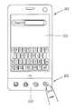
제1 바디(201), 주로 프론트 케이스(201a)에는 디스플레이 모듈(251), 음향출력부(252), 카메라(221), 사용자 입력부(230/231,232), 마이크(222), 인터페이스(270) 등이 배치될 수 있다.The
디스플레이 모듈(251)은 프론트 케이스(201a)의 주면의 대부분을 차지한다. 디스플레이 모듈(251)의 양단부 중 일 단부에 인접한 영역에는 음향출력부(251)와 카메라(221)가 배치되고, 다른 단부에 인접한 영역에는 마이크(222)가 배치된다. 사용자 입력부(230)는 제1 및 제2 바디(201, 202)에 배치되며, 인터페이스(270)는 프론트 케이스(201a) 및 리어 케이스(201b)의 측면들에 배치될 수 있다.The
사용자 입력부(230)는 휴대 단말기(200)의 동작을 제어하기 위한 명령을 입력받기 위해 조작되는 것으로서, 복수의 조작 유닛들(231, 232)을 포함할 수 있다. 조작 유닛들(231, 232)은 조작부(manipulating portion)로도 통칭 될 수 있으며, 사용자가 촉각 적인 느낌을 가면서 조작하게 되는 방식(tactile manner)이라면 어떤 방식이든 채용될 수 있다.The
제1 또는 제2조작 유닛들(231, 232)에 의하여 입력되는 내용은 다양하게 설정될 수 있다. 예를 들어, 제1 조작 유닛(231)은 시작, 종료, 스크롤 등과 같은 명령을 입력받고, 제2 조작 유닛(232)은 음향출력부(252)에서 출력되는 음향의 크기 조절 또는 디스플레이 모듈(251)의 터치 인식 모드로의 전환 등과 같은 명령을 입력받을 수 있다. 디스플레이 모듈(251)은 터치센서(251c, 도 3 참조)와 함께 터치 스크린을 형성하며, 터치 스크린은 사용자 입력부(230)의 일 예가 될 수 있다.The contents inputted by the first or
도시에 의하면, 제1 조작유닛(231)은 제2 바디(202)에서 투광성 디스플레이 모듈(253)이 활성화됨에 의하여 구현된다. 여기서 '투광성'은 완전 투광성(transparent) 및 반투광성(translucent, semi-transparent)을 포함하는 의미이다.According to the illustration, the
투광성 디스플레이 모듈(253)은 도 2c과 같이 활성화되기 전에는 키패턴 등의 시각정보를 디스플레이하지 않고 투명한 성질을 가지다가, 도 2a와 같이 투광성 디스플레이 모듈이 활성화되면 상기 시각 정보를 디스플레이하도록 이루어진다.The
도 2b를 참조하면, 단말기 바디의 후면, 다시 말해서 리어 케이스(201b)에는 카메라(221')가 추가로 장착될 수 있다. 카메라(221')는 카메라(221, 도 2a 참조)와 실질적으로 반대되는 촬영 방향을 가지며, 카메라(221)와 서로 다른 화소를 가지는 카메라일 수 있다.Referring to FIG. 2B, a camera 221 'may be further mounted on the rear surface of the terminal body, that is, the
예를 들어, 카메라(221)는 화상 통화 등의 경우에 사용자의 얼굴을 촬영하여 상대방에 전송함에 무리가 없도록 저 화소를 가지며, 카메라(221')는 일반적인 피사체를 촬영하고 바로 전송하지는 않는 경우가 많기에 고 화소를 가지는 것이 바람직하다. 카메라(221,221')는 회전 또는 팝업(pop-up) 가능하게 단말기 바디에 설치될 수도 있다.For example, the
카메라(221')에 인접하게는 플래쉬(223)와 거울(224)이 추가로 배치된다. 플래쉬(223)는 카메라(221')로 피사체를 촬영하는 경우에 피사체를 향해 빛을 비추게 된다. 거울(224)은 사용자가 카메라(221')를 이용하여 자신을 촬영(셀프 촬영)하고자 하는 경우에, 사용자 자신의 얼굴 등을 비춰볼 수 있게 한다.A
단말기 바디의 후면에는 음향 출력부(252')가 추가로 배치될 수도 있다. 음향 출력부(252')는 음향 출력부(252, 도 2a 참조)와 함께 스테레오 기능을 구현할 수 있으며, 통화시 스피커폰 모드의 구현을 위하여 사용될 수도 있다.An acoustic output unit 252 'may be further disposed on the rear surface of the terminal body. The sound output unit 252 'may implement the stereo function together with the sound output unit 252 (see FIG. 2A), and may be used for the implementation of the speakerphone mode in a call.
단말기 바디의 측면에는 통화 등을 위한 안테나 외에 방송신호 수신용 안테나(216)가 추가적으로 배치될 수 있다. 방송수신모듈(111, 도 1 참조)의 일부를 이루는 안테나(216)는 단말기 바디에서 인출 가능하게 설치될 수 있다.In addition to the antenna for talking and the like, a broadcast signal reception antenna 216 may be additionally disposed on the side of the terminal body. The antenna 216 constituting a part of the broadcast receiving module 111 (see FIG. 1) can be installed to be able to be drawn out from the terminal body.
단말기의 제1 바디(201)에는 이동 단말기(200)에 전원을 공급하기 위한 전원공급부(290)가 장착된다. 전원공급부(290)는 단말기 바디에 내장되거나, 단말기 바디의 외부에서 직접 탈착될 수 있게 구성될 수 있다.The
리어 케이스(201b)에는 터치를 감지하기 위한 터치센서가 추가로 장착될 수 있다. 터치센서 또한 디스플레이 모듈(251)과 마찬가지로 광 투과형으로 구성될 수 있다. 이 경우에, 디스플레이 모듈(251)이 양면에서 시각 정보를 출력하도록 구성된다면, 터치센서를 통해서도 상기 시각 정보를 인지할 수 있게 된다. 상기 양면에 출력되는 정보는 상기 터치센서에 의해 모두 제어될 수도 있다. 이와 달리, 터치센서에는 디스플레이가 추가로 장착되어, 리어 케이스(201b)에도 터치 스크린이 배치될 수도 있다.The
터치센서는 프론트 케이스(201a)의 디스플레이 모듈(251)과 상호 관련되어 작동한다. 터치센서는 디스플레이 모듈(251)의 후방에 평행하게 배치될 수 있다. 이러한 터치센서는 디스플레이 모듈(251)과 동일하거나 작은 크기를 가질 수 있다.The touch sensor operates in correlation with the
본 도면들을 참조하면, 제2 바디(202)의 투광성 디스플레이 모듈(253)를 통하여 사용자는 새로운 사용감을 느낄 수 있게 된다. 이하 제2 바디(202)의 구조에 대하여 보다 상세하게 설명한다.Referring to these drawings, a user can feel a new feeling through the
도 3은 도 2c의 이동 단말기의 분해도이고, 도 4는 도 3의 제2 바디의 확대도이며, 도 5는 도 3의 라인 Ⅴ-Ⅴ를 따라 취한 단면도이다.Fig. 3 is an exploded view of the mobile terminal of Fig. 2c, Fig. 4 is an enlarged view of the second body of Fig. 3, and Fig. 5 is a sectional view taken along line V-V of Fig.
도 3을 참조하면, 프론트 케이스(201a)의 일 면에는 윈도우(251a)가 결합 된다. 윈도우(251a)는 빛이 투과할 수 있는 소재, 예를 들어 투광성 합성수지, 강화 유리 등으로 구성된다. 다만 윈도우(251a)는 빛이 투과할 수 없는 부분을 포함할 수 있다.Referring to FIG. 3, a
윈도우(251a)의 후면에는 디스플레이(251b)가 장착될 수 있다. 디스플레이(251b)는 시각 정보를 표시하며, 상기 윈도우(251a)에 의하여 덮이도록 배치된다. 디스플레이(251b)는, 예를 들어 액정 디스플레이(liquid crystal display, LCD), 박막 트랜지스터 액정 디스플레이(thin film transistor-liquid crystal display, TFT LCD), 유기 발광 다이오드(organic light-emitting diode, OLED), 플렉시블 디스플레이(flexible display), 3차원 디스플레이(3D display) 중에서 어느 하나가 될 수 있다.A
윈도우(251a)는 디스플레이(251b)를 덮도록 배치되고, 윈도우(251a)의 빛이 투과되는 부분은 디스플레이(251b)에 대응하는 면적을 가질 수 있다. 이를 통하여 사용자는 디스플레이(251b)에서 출력되는 시각 정보를 외부에서 인지할 수 있게 된다.The
리어 케이스(201b)에는 회로기판(281)이 장착될 수 있다. 회로기판(281)은 이동 단말기의 각종 기능을 동작시키기 위한 제어부(180, 도 1 참조)의 일 예로서 구성될 수 있다.The
도시에 의하면, 윈도우(251a)에는 터치센서(251c)가 장착될 수 있다.According to the drawing, the
터치센서(251c)는 윈도우(251a)의 후면에 장착될 수 있으며, 윈도우(251a)의 빛이 투과되는 부분은 터치센서(251c)를 통하여 입력이 가능한 영역을 형성한다. 터치센서(251c)는 투광성으로 이루어지며, 터치 입력을 감지하도록 윈도우(251a)의 특정 부위에 발생하는 전압, 커패시턴스 등의 변화를 전기적인 입력신호로 변환한다.The
이와 같이, 윈도우(251a), 터치센서(251c) 및 디스플레이(251b)는 디스플레이 모듈(251, 도 2a 참조)로서 구성될 수 있으며, 디스플레이 모듈(251)은 터치 스크린으로 동작하게 된다. 이 경우, 터치 스크린은 회로기판(281)에 의하여 제어될 수 있다.Thus, the
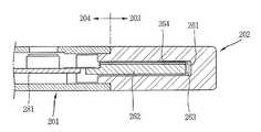
본 도면들을 참조하면, 제1 바디(201)에는 투광성의 재질로 형성되는 제2 바디(202)가 장착된다. 제1 바디(201)는 일단이 개방되며, 이를 통하여 제1 바디(201)의 내부공간은 제2 바디(202)의 내부공간과 연통된다.Referring to these drawings, a
보다 구체적으로, 제2 바디(202)는 도 4 및 도 5에 도시된 바와 같이 리세스부(261), 투광성 디스플레이(262) 및 충전제(263)를 포함한다.More specifically, the
리세스부(261)는 제2 바디(202)의 일면에서 제1 바디(201)와 멀어지는 방향으로 리세스되도록 형성된다. 리세스부(261)에 의하여 제2 바디(202)의 내부공간이 형성되도록 제2 바디(202)의 케이스는 일측이 개방된 단일의 케이스로 이루어진다. 즉, 제2 바디(202)는 투광성 디스플레이(262)가 내장되는 단일 케이스를 포함하고, 단일 케이스는 투광성 재질로 형성되며, 리세스부(261)는 상기 단일 케이스의 내부공간을 형성한다.The
투광성 디스플레이(262)는 리세스부(261)에 삽입되며, 회로기판(281)과 전기적으로 연결된다. 투광성 디스플레이(262)는 투광성 재질로 이루어지며, 투명한 공간에서 시각정보를 표시하도록 형성된다. 이러한 투광성 디스플레이(262)의 일 예로서, 상기 투광성 디스플레이(262)는 TOLED(Transparant OLED)가 될 수 있다.The
충전제(263)는 투광성 재질로 이루어지며, 투광성 디스플레이(262)가 삽입된 리세스부(261)의 빈 공간을 채우도록 상기 리세스부(261)에 충전된다. 충전제(263)는 투광성 디스플레이(262)의 주변에서 빛의 반사를 억제하도록 리세스부(261)의 빈 공간 중 제1 바디(201)의 외부로 노출되는 부분을 채우게 된다.The
충전제(263)는 상기 빈 공간을 채우면서 제2 바디(202)에 투광성 디스플레이(262)를 부착시키도록 형성된다. 부착기능이 가능하도록, 충전제(263)는 액상에서 고상으로 경화되는 광학탄성수지(SVR, Super View Resin)로 형성될 수 있다.The
충전제(263)의 충전방법에 대하여 예를 들어 설명한다. 먼저, 제2 바디(202)의 리세스부(261)에 기설정된 높이로 액상의 광학탄성수지를 채우고, 다음은 투광성 디스플레이(262)를 리세스부(261)에 삽입한다. 그 후에 상온경화, 자외선조사에 의한 경화 또는 열경화 등을 이용하여 광학탄성수지를 경화시킨다.A method of charging the
상기 충전방법은 진공상태에서 이루어지며, 이를 통하여 충전제(263)의 내부에서 기포발생이 억제될 수 있다. 진공상태를 유지하기 위하여 제2 바디(202)가 진공챔버에 배치된 상태에서 충전제(263)의 경화가 이루어질 수 있다.The charging method is performed in a vacuum state, and bubble generation can be suppressed through the
이와 같이, 투광성의 단일 케이스에 투광성 디스플레이(262)가 삽입되고, 투광성 충전제(263)가 충전됨에 따라 투광성 디스플레이 모듈(253, 도 2a 및 도 2c 참조)이 구현될 수 있다. 또한, 충전제(263)가 빈공간을 채우게 되므로, 케이스와 디스플레이(262)의 이격공간에서 빛의 투과도가 향상되며, 경계가 없는 일체의 투명 바디가 구현될 수 있다.As described above, the transmissive display module 252 (see Figs. 2A and 2C) can be implemented as the
이상, 투광성 디스플레이를 예를 들어 설명하였으나, 본 발명은 반드시 이에 한정되지 않는다. 예를 들어, 투광성 디스플레이(262)의 위치에 LCD와 같은 불투과성 디스플레이가 배치되면, 투명은 아니더라도 충전제의 충전에 의하여 시인성이 보다 우수한 디스플레이 모듈이 구현될 수 있다.As described above, the translucent display has been described by way of example, but the present invention is not limited thereto. For example, if an impermeable display such as an LCD is disposed at the position of the
다시 도 4 및 도 5를 참조하면, 제2 바디(202)는 노출부분(203) 및 수용부분(204)을 포함한다.Referring again to Figures 4 and 5, the
노출부분(203)는 제1 바디(201)의 외부에 배치되며, 투광성 디스플레이(262)에 의하여 시각정보가 디스플레이되도록 이루어진다. 노출부분(203)은 이동 단말기(200)의 외관의 일부를 구성한다. 노출부분(203)에는 장식적인 고려에 의하여 다양한 변형된 형상이 적용될 수 있다.The exposed
충전제(263)는 리세스부(261)에 노출부분(203)으로부터 상기 경계를 지나도록 충전된다. 즉, 노출부분(203)에는 충전제(263)가 완전히 채워지며, 이를 통하여 노출부분(203)은 빈 공간이 없는 일체의 투명 외관을 형성하게 된다.The
수용부분(204)은 노출부분(203)으로부터 연장되어 제1 바디(201)의 내부에 삽입된다. 수용부분(204)이 제1 바디(201)에 삽입되면 수용부분(204)과 노출부분(203)의 경계가 상기 제1 바디(201)의 일면에 걸리도록, 상기 수용부분(204)과 노출부분(203)의 주면은 서로 단지도록 이루어진다.The receiving
보다 구체적으로, 수용부분(204)은 프론트 케이스(201a) 및 리어 케이스(201b)의 두께와 합하여져 노출부분(203)의 두께에 상응할 수 있도록 노출부분(203)보다는 두께가 얇게 형성될 수 있다. 이를 통하여, 노출부분(203)의 외면은 제1 바디(201)의 외면과 동일평면을 이룰수 있다.More specifically, the receiving
수용부분(204)은 베이스부(204a) 및 체결부(204b)를 포함한다.The receiving
베이스부(204a)는 노출부분(203)의 일단에서 제1 바디(201)를 향하여 연장되도록 형성되며, 베이스부(204a)에는 리세스부(261)의 개구가 배치된다.The
체결부(204b)는 베이스부(204a)의 양단 중 적어도 하나에서 돌출되며, 상기 제1 바디(201)에 체결되도록 이루어진다. 도 4에 의하면, 체결부(204b)는 리세스부의 개구를 중심으로 좌우 대칭으로 형성되며, 케이스(201a, 201b)와 스크루에 의하여 체결되도록 체결홀(204c)을 구비한다.The
이러한 체결부(204b)는 노출부분(203)이 외부로부터 충격이나 지속적인 힘을 받고 있을 때 제2 바디(202)가 제1 바디(201)에 견고하게 고정된 상태를 유지할 수 있을 정도의 지지력을 발휘하게 된다. 체결부(204b)는 제2 바디(202)의 단일 케이스의 성형시 함께 성형되도록 함으로써 이를 형성하기 위한 별도의 부재의 필요를 수반하지 않는다.The
본 도면들을 참조하면, 투광성 디스플레이(253)에는 전기적 연결 경로를 형성하도록 연성회로기판(282)이 결합하며, 상기 연성회로기판(282)은 수용부분(204)에 배치된다. 연성회로기판(282)은, 예를 들어 회로기판(281)과 전기적으로 연결되며, 이를 통하여 회로기판(281)은 투광성 디스플레이(262)를 제어한다.Referring to these drawings, a
충전제(263)는 연성회로기판(282)을 고정시키도록 수용부분(204)에서 상기 연성회로기판(282)과 리세스부(261)의 사이를 채운다. 즉, 충전제(263)는 연성회로기판(282)을 고정시키도록 수용부분(204)까지 충전될 수 있다.The
도 5를 참조하면, 투광성 디스플레이 모듈(253)은 터치센서(264)를 포함하여 투광성 터치 스크린이 될 수 있다. 예를 들어, 리세스부(261)에는 제2 바디(202)에 대한 터치 입력을 감지하도록 터치센서(264)가 삽입된다.5, the
터치센서(264)는 광투과성으로 이루어지며, 터치 입력을 감지하도록 제2 바디(202)의 특정 부위에 발생하는 전압, 커패시턴스 등의 변화를 전기적인 입력신호로 변환한다.The
보다 구체적으로, 터치센서(264)는 투광성 디스플레이(262)에 장착되며, 충전제(263)는 터치센서(264)와 리세스부(261)의 내면 사이를 충전한다. 이를 통하여, 터치센서(264)는 투광성 디스플레이(262)에 장착된 채로, 투광성 디스플레이(262)와 함께 리세스부(261)에 삽입될 수 있다.More specifically, the
이와 같이, 터치센서(264)가 리세스부에 삽입됨에 따라, 다양한 유저 인터페이스가 가능하게 된다. 이하, 도 6a 내지 도 7b를 참조하여 도 3의 단말기에 적용되는 유저 인터페이스에 대하여 예를 들어 설명한다.As described above, as the
도 6 내지 도 8b은 각각 도 3의 단말기에 적용되는 유저 인터페이스를 나타내는 개념도들이다.6 to 8B are conceptual diagrams illustrating a user interface applied to the terminal of FIG. 3, respectively.
도 6 및 도 7을 참조하면, 제2 바디(202)의 터치센서(264, 도 5 참조)는 제1 바디(201)의 디스플레이 모듈(251)에 대한 제어 명령을 감지하도록 이루어진다.6 and 7, the touch sensor 264 (see FIG. 5) of the
예를 들어, 제2 바디(202)에는 이동 단말기의 각 모드에 진입하기 위한 메뉴키가 디스플레이되고, 메뉴키의 터치에 따라서 디스플레이 모듈(251)에는 이에 대응하는 모드가 실행된다. 도 6은 검색키의 터치에 의하여 검색 모드가 실행되는 경우를 예시한다.For example, a menu key for entering each mode of the mobile terminal is displayed on the
다른 예로 도 7과 같이, 제2 바디(202)에는 문자 입력을 위한 입력창이 디스플레이되고, 입력창을 통하여 터치 방식으로 입력되는 문자가 디스플레이 모듈(251)에 디스플레이된다.As another example, as shown in FIG. 7, an input window for inputting characters is displayed on the
도 8a 및 도 8b를 참조하면, 투광성 디스플레이는 제1 바디(201)의 터치 스크린에 입력되는 터치 입력에 의하여 제어될 수 있다.8A and 8B, the translucent display can be controlled by a touch input input to the touch screen of the
예를 들어, 제1 바디(201)의 디스플레이 모듈(251)은 터치 스크린으로 이루어지고, 디스플레이 모듈(251)에는 전화번호를 입력받기 위한 입력키가 디스플레이되며, 제2 바디(202)의 투광성 디스플레이 모듈(253)에는 호신호 연결 및 통화 종료키가 디스플레이된다. 사용자가 호신호 연결키를 터치하면, 디스플레이 모듈(251)에는 통화 연결을 나타내는 정보가 디스플레이된다.For example, the
이상과 같이, 투광성 디스플레이 모듈(253)은 제1 바디(201)의 디스플레이 모듈(251)과 조합되어 다양한 유저 인터페이스를 구현할 수 있다.As described above, the light
이하, 본 발명의 투광성 디스플레이 모듈와 관련한 다른 실시예들에 대하여 설명한다.Hereinafter, other embodiments related to the translucent display module of the present invention will be described.
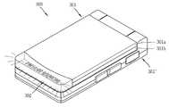
도 9a 및 도 9b는 각각 본 발명의 투광성 디스플레이 모듈이 폴더형 단말기에 적용된 경우에 닫힌 및 열린 상태를 나타내는 사시도들이고, 도 10은 도 9a의 제1 폴더바디(301)에 대한 분해도이며, 도 11은 도 10의 A 부분에 대한 확대도이다.FIGS. 9A and 9B are perspective views showing a closed and open state when the translucent display module of the present invention is applied to a folder type terminal, FIG. 10 is an exploded view of the
본 도면들에서 보는 것과 같이, 이동 단말기(300)는 서로에 대해 폴딩 가능하게 결합되는 제1 폴더바디(301)와 제2 폴더바디(301')를 구비하고 있다. 다만, 본 실시예와 관련된 구조들은 본 도면들에 개시된 타입의 이동 단말기에 한하지 않으며, 슬라이드 타입, 스윙 타입, 스위블 타입 등과 같이 2 이상의 바디들이 상대 이동 가능하게 결합되는 구조에 모두 적용이 가능하다.As shown in the drawings, the
제2 폴더바디(301')의 전면이 외부로 노출된 도 9b와 같은 상태를 열린 상태(open configuration)라 칭할 수 있으며, 제2 폴더바디(301')의 노출되었던 전면이 도 9a와 같이 제1 폴더바디(301)에 의하여 가려진 상태를 닫힌 상태(closed configuration)라 칭할 수 있다.The state shown in FIG. 9B in which the front surface of the second folder body 301 'is exposed to the outside can be referred to as an open configuration, and the exposed front surface of the second folder body 301' 1, the closed state by the
본 실시예에서 제1 폴더바디(301)는 앞서 도 3에 도시된 실시예에서 제1 바디에 대응된다. 또한, 본 실시에서 도 3에서 도시된 실시예와 동일·유사한 구성에 대한 설명은 처음 설명으로 갈음한다.In this embodiment, the
도 9a를 참조하면, 제1 폴더바디(301)의 외측면에는 제2 바디(302)가 설치될 수 있다.Referring to FIG. 9A, a
제2 바디(302)는 폴딩바디(301)를 열지 않고도 이동 단말기(300)의 각종 상태 정보나 사용자 컨텐츠 등을 출력하도록 구성될 수 있다. 즉, 제2 바디(302)에서 시각 정보의 표시는 제2 바디(302)의 외면을 향하도록 이루어진다.The
나아가 제2 바디(302)는 이동 단말기(300)가 갖는 각종 모드와 관련된 디스플레이가 가능하도록 이루어지며, 다양한 조명효과를 구현하도록 구성된다. 예를 들어, 이동 단말기(300)에 외부에서 전화가 걸려 오거나 문자메시지를 수신하는 경우 제2 바디(302)를 통하여 이에 대응되는 시각 정보를 제공할 수 있다. 이외에도 이동 단말기(300)의 닫힌 상태에서 제2 바디(302)는 시계로서 활용될 수 있다.Further, the
도 9b를 참조하면, 제1 폴더바디(301)의 내측면에는 음향 출력부(352) 및 디스플레이 모듈(351)이 설치되어 있으며, 제2 바디(302)의 정보 표시는 제2 바디(302)의 내면을 향하도록 전환된다.9B, an
디스플레이 모듈(351)은 이동 단말기(300)가 갖는 각종 모드에서의 사용자 인터페이스(User Interface), 편집중인 정보, 사용자 컨텐츠 등을 출력한다. 디스플레이 모듈(351)를 통하여 출력되는 화면은 이동 단말기(300)의 자세에 따라 변환되도록 구성될 수 있다. 예를 들어, 디스플레이 모듈(351)를 통하여 출력되는 화면은 회전되거나 크기조정될 수 있으며, 제2 바디(302)에서 출력되는 화면은 디스플레이 모듈(351)의 변화에 대응하여 가변될 수 있다.The
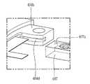
도 10을 참조하면, 제2 바디(302)에서 수용부분(304)의 체결부(304b)는 베이스부(304a)의 양단에서 각각 돌출되도록 복수로 구비되며, 복수의 체결부들의 사이에는 스피커(352a)가 배치된다. 이와 같이, 스피커(352a)가 수용부분(304)의 오목한 영역에 배치됨에 따라 보다 컴팩트한 구성이 가능하게 되다.10, a plurality of
제1 폴더바디(301)에는 디스플레이 모듈(351, 도 9b 참조)을 구성하며, 회로기판(미도시)에 의하여 제어되는 디스플레이(351b)가 장착된다.The
도시에 의하면, 제1 폴더바디(301)의 케이스들(301a, 301b)에는 디스플레이(351b)를 지지하도록 이루어지는 프레임(305)이 장착되며, 체결부(304b)는 상기 프레임(305)에 의하여 고정된다.A
프레임(305)은 지지부(306) 및 돌출부(307)를 포함한다.The
지지부(306)는 디스플레이(351b)를 지지하도록 상기 디스플레이(351b)의 가장자리를 따라 형성된다. 보다 구체적으로, 지지부(306)는 폐루프를 이루며, 디스플레이(351b)의 가장자리를 지지하도록 이루어진다.The
돌출부(307)는 지지부에서 돌출되며, 돌출부(307)에는 제1 폴더바디(301)의 케이스들(301a, 301b)에 스크류에 의하여 결합되도록 관통홀(308)이 형성된다.The protruding
본 도면들을 참조하면, 체결부(304b)는 제1 폴더바디(301)의 케이스들(301a, 301b)에 체결되며, 프레임(305)은 적어도 일부가 체결부(304b)를 덮도록 이루어진다. 예를 들어, 제2 바디(302)의 체결부(304b)는 디스플레이(351b)를 관통하는 방향으로 상기 돌출부(307)에 의하여 덮이도록 이루어진다. 돌출부(307)가 체결부(304b)를 덮기 위하여, 돌출부(307)의 측면에는 수용홈(307a)이 형성되고, 체결부(304b)에는 수용돌기(304d)가 구비된다. 수용홈(307a)에 수용돌기(304d)가 수용되면서, 수용돌기(304d)는 돌출부(307)에 의하여 덮이게 된다.Referring to these figures, the
이런 구조에서는 제2 바디(302)를 리어 케이스(301a)에 배치한 상태에서 프레임을 리어 케이스(301a)에 체결하면, 제2 바디(302)가 고정될 수 있다. 보다 견고한 결합을 위하여 체결부(304b)가 체결홀(304c)을 통하여 리어 케이스(301a)에 스크류 체결된다. 이와 같이, 프레임(305)에 의하여 제2 바디(302)가 고정되므로, 별도의 보강구조가 없는 제2 바디(302)의 외관이 가능하게 된다.In this structure, the
도 12은 제1 폴더바디(401)의 변형예에 대한 분해도이며, 도 13은 도 11의 B 부분에 대한 확대도이다.FIG. 12 is an exploded view of a modified example of the
도시에 의하면, 제2 바디(402)의 체결부(404b)는 프레임(405)의 돌출부(407)의 적어도 일부가 슬라이딩에 의하여 끼워지도록 형성된다. 이를 위하여, 체결부(404b)에는 삽입 가이드(404d)가 형성되며, 돌출부(407)에는 상기 삽입 가이드(404d)에 슬라이딩 방식으로 끼워지는 삽입 날개(407a)가 형성된다.According to the view, the
상기 구조를 통하여, 제2 바디(402)는 프레임(405)에 슬라이딩 방식으로 끼워진 상태에서 제1 폴더바디(401)의 리어 케이스(401a)에 장착될 수 있다.The
이상에서 설명된 이동 단말기는 상기 설명된 실시예들의 구성과 방법이 한정되게 적용될 수 있는 것이 아니라, 상기 실시예들은 다양한 변형이 이루어질 수 있도록 각 실시예들의 전부 또는 일부가 선택적으로 조합되어 구성될 수도 있다.The mobile terminal described above can be applied not only to the configuration and method of the embodiments described above but also to the embodiments described above so that all or some of the embodiments may be selectively combined have.
Claims (20)
Translated fromKorean투광성의 재질로 형성되며, 단말기의 부분적인 외관을 형성하도록 상기 제1 바디에 장착되는 제2 바디를 포함하고,
상기 제2 바디는,
상기 제2 바디의 일면에서 상기 제1 바디와 멀어지는 방향으로 리세스되는 리세스부;
상기 리세스부에 삽입되고, 투광성 재질로 이루어지며, 시각정보를 표시하도록 형성되는 투광성 디스플레이; 및
상기 투광성 디스플레이가 삽입된 리세스부의 빈 공간을 채우도록 상기 리세스부에 충전되며, 투광성 재질로 이루어지는 충전제를 포함하고,
상기 제2 바디는,
상기 제1 바디의 외부에 배치되며, 상기 투광성 디스플레이에 의하여 시각정보가 디스플레이되는 노출부분; 및
상기 노출부분으로부터 연장되어 상기 제1 바디의 내부에 삽입되는 수용부분을 포함하고,
상기 수용부분은,
상기 노출부분의 일단에서 상기 제1 바디를 향하여 연장되며, 상기 리세스부의 개구가 배치되는 베이스부; 및
상기 베이스부의 양단 중 적어도 하나에서 돌출되며, 상기 제1 바디에 체결되도록 이루어지는 체결부를 포함하는 이동 단말기.A first body; And
And a second body formed of a transparent material and mounted on the first body to form a partial appearance of the terminal,
The second body may include:
A recessed portion which is recessed in a direction away from the first body on one side of the second body;
A translucent display inserted in the recess portion and made of a translucent material, the translucent display formed to display time information; And
And a filler made of a translucent material, the filler being filled in the recess portion to fill the void space of the recessed portion into which the translucent display is inserted,
The second body may include:
An exposed portion disposed outside the first body, wherein the exposed portion displays visual information by the translucent display; And
And a receiving portion extending from the exposed portion and being inserted into the first body,
The receiving portion includes:
A base portion extending from the one end of the exposed portion toward the first body and having an opening in the recessed portion; And
And a fastening portion protruded from at least one of both ends of the base portion and fastened to the first body.
상기 충전제는 상기 빈 공간을 채우면서 상기 제2 바디에 상기 투광성 디스플레이를 부착시키도록 형성되는 것을 특징으로 하는 이동 단말기.The method according to claim 1,
Wherein the filler is formed to attach the translucent display to the second body while filling the void space.
상기 충전제는 상기 투과성 디스플레이의 주변에서 빛의 반사를 억제하도록 상기 빈 공간 중 상기 제1 바디의 외부로 노출되는 부분을 채우는 것을 특징으로 하는 이동 단말기.3. The method of claim 2,
Wherein the filler fills a portion of the void space exposed to the outside of the first body so as to suppress reflection of light at the periphery of the transmissive display.
상기 충전제는 액상에서 고상으로 경화되는 광학탄성수지(SVR, Super View Resin)로 이루어지는 것을 특징으로 하는 이동 단말기.The method of claim 3,
Wherein the filler comprises a super-view resin (SVR) cured in a liquid phase to a solid phase.
상기 리세스부에는 상기 제2 바디에 대한 터치 입력을 감지하도록 터치센서가 삽입되는 것을 특징으로 하는 이동 단말기.The method according to claim 1,
Wherein the touch sensor is inserted into the recess portion to sense touch input to the second body.
상기 터치센서는 상기 투광성 디스플레이에 장착되며, 상기 충전제는 상기 터치센서와 상기 리세스부의 내면 사이를 충전하는 것을 특징으로 하는 이동 단말기.6. The method of claim 5,
Wherein the touch sensor is mounted on the transmissive display, and the filler is filled between the touch sensor and the inner surface of the recess portion.
상기 제1 바디에는 터치 스크린이 형성되고, 상기 터치센서는 상기 터치 스크린에 대한 제어 명령을 감지하도록 이루어지는 것을 특징으로 하는 이동 단말기.The method according to claim 6,
Wherein the first body is formed with a touch screen, and the touch sensor senses a control command to the touch screen.
상기 투광성 디스플레이는 상기 터치 스크린에 입력되는 터치 입력에 의하여 제어되는 것을 특징으로 하는 이동 단말기.8. The method of claim 7,
Wherein the light transmissive display is controlled by a touch input input to the touch screen.
상기 투광성 디스플레이에는 상기 투광성 디스플레이를 제어하는 회로기판과 전기적으로 연결되도록 연성회로기판이 결합하며,
상기 연성회로기판은 상기 수용부분에 배치되는 것을 특징으로 하는 이동 단말기.The method according to claim 1,
The flexible printed circuit board is coupled to the light transmissive display so as to be electrically connected to a circuit board for controlling the transmissive display,
And the flexible circuit board is disposed in the receiving portion.
상기 충전제는 상기 연성회로기판을 고정시키도록 상기 수용부분에서 상기 연성회로기판과 상기 리세스부의 사이를 채우는 것을 특징으로 하는 이동 단말기.11. The method of claim 10,
Wherein the filler fills the space between the flexible circuit board and the recessed portion in the receiving portion so as to fix the flexible circuit board.
상기 수용부분이 상기 제1 바디에 삽입되면 상기 수용부분과 노출부분의 경계가 상기 제1 바디의 일면에 걸리도록, 상기 수용부분과 노출부분의 주면은 서로 단지도록 이루어지는 것을 특징으로 하는 이동 단말기.The method according to claim 1,
Wherein the receiving portion and the main surface of the exposed portion are formed so that a boundary between the receiving portion and the exposed portion is caught on one surface of the first body when the receiving portion is inserted into the first body.
상기 충전제는 상기 노출부분으로부터 상기 경계를 지나도록 상기 리세스부에 충전되는 것을 특징으로 하는 이동 단말기.13. The method of claim 12,
Wherein the filler is filled in the recess portion from the exposed portion through the boundary.
상기 제1 바디에는 시각정보를 표시하는 디스플레이와, 상기 디스플레이를 지지하도록 이루어지는 프레임이 장착되고,
상기 체결부는 상기 프레임에 의하여 고정되는 것을 특징으로 하는 이동 단말기.The method according to claim 1,
A display for displaying time information on the first body; a frame for supporting the display;
And the fastening portion is fixed by the frame.
상기 프레임은,
상기 디스플레이를 지지하며, 상기 디스플레이의 가장자리를 따라 형성되는 지지부; 및
상기 지지부에서 돌출되며, 상기 제1 바디에 결합되도록 관통홀을 구비하는 돌출부를 포함하는 이동 단말기.16. The method of claim 15,
The frame includes:
A support for supporting the display, the support being formed along an edge of the display; And
And a protrusion protruding from the support portion and including a through hole to be coupled to the first body.
상기 체결부는 상기 디스플레이를 관통하는 방향으로 상기 돌출부에 의하여 덮이도록 이루어지며,
상기 체결부에는 상기 제1 바디와 결합하도록 체결홀이 형성되는 것을 특징으로 하는 이동 단말기.17. The method of claim 16,
The fastening portion is configured to be covered by the projection in a direction passing through the display,
Wherein the fastening portion is formed with a fastening hole to be engaged with the first body.
상기 체결부에는 상기 돌출부의 적어도 일부가 슬라이딩에 의하여 끼워지도록 삽입 가이드가 형성되는 것을 특징으로 하는 이동 단말기.17. The method of claim 16,
Wherein the fastening portion is formed with an insertion guide so that at least a part of the protruding portion is inserted by sliding.
상기 체결부는 상기 제1 바디의 케이스에 체결되며, 상기 프레임은 적어도 일부가 상기 체결부를 덮도록 이루어지는 것을 특징으로 하는 이동 단말기.16. The method of claim 15,
Wherein the fastening portion is fastened to the case of the first body, and at least a part of the frame covers the fastening portion.
상기 제2 바디는 상기 투광성 디스플레이가 내장되는 단일 케이스를 포함하며, 상기 리세스부는 상기 단일 케이스의 내부공간을 형성하는 것을 특징으로 하는 이동 단말기.The method according to claim 1,
Wherein the second body includes a single case in which the transmissive display is embedded, and the recess portion forms an internal space of the single case.
Priority Applications (4)
| Application Number | Priority Date | Filing Date | Title |
|---|---|---|---|
| KR1020100092677AKR101629264B1 (en) | 2010-09-20 | 2010-09-20 | Mobile terminal |
| US13/208,600US9008731B2 (en) | 2010-09-20 | 2011-08-12 | Mobile terminal |
| EP11006819.4AEP2432195B1 (en) | 2010-09-20 | 2011-08-19 | Mobile terminal |
| CN201110277560.8ACN102413206B (en) | 2010-09-20 | 2011-09-19 | Mobile terminal |
Applications Claiming Priority (1)
| Application Number | Priority Date | Filing Date | Title |
|---|---|---|---|
| KR1020100092677AKR101629264B1 (en) | 2010-09-20 | 2010-09-20 | Mobile terminal |
Publications (2)
| Publication Number | Publication Date |
|---|---|
| KR20120030866A KR20120030866A (en) | 2012-03-29 |
| KR101629264B1true KR101629264B1 (en) | 2016-06-10 |
Family
ID=44581983
Family Applications (1)
| Application Number | Title | Priority Date | Filing Date |
|---|---|---|---|
| KR1020100092677AExpired - Fee RelatedKR101629264B1 (en) | 2010-09-20 | 2010-09-20 | Mobile terminal |
Country Status (4)
| Country | Link |
|---|---|
| US (1) | US9008731B2 (en) |
| EP (1) | EP2432195B1 (en) |
| KR (1) | KR101629264B1 (en) |
| CN (1) | CN102413206B (en) |
Families Citing this family (11)
| Publication number | Priority date | Publication date | Assignee | Title |
|---|---|---|---|---|
| KR101515629B1 (en) | 2012-01-07 | 2015-04-27 | 삼성전자주식회사 | Method and apparatus for providing event of portable device having flexible display unit |
| KR101462540B1 (en)* | 2012-06-14 | 2014-11-18 | 삼성디스플레이 주식회사 | Dual display device and Controlling method of the same |
| KR101801554B1 (en) | 2013-07-11 | 2017-11-27 | 삼성전자주식회사 | User terminal device for displaying contents and methods thereof |
| US9337881B2 (en) | 2013-11-22 | 2016-05-10 | Motorola Solutions, Inc. | Apparatus for providing information on a top section of a portable radio |
| FR3021134B1 (en) | 2014-05-14 | 2023-01-06 | Lg Electronics Inc | MOBILE TERMINAL |
| KR101659028B1 (en)* | 2014-06-17 | 2016-09-23 | 엘지전자 주식회사 | Mobile terminal and method of controlling the same |
| CN105578811B (en)* | 2014-10-17 | 2018-09-04 | 小米科技有限责任公司 | Electronic equipment and electronic equipment application method |
| KR101760012B1 (en) | 2016-01-08 | 2017-07-31 | 엘지전자 주식회사 | Mobile terminal |
| CN205485162U (en)* | 2016-01-13 | 2016-08-17 | 群创光电股份有限公司 | Display device |
| CN109327565A (en)* | 2017-07-31 | 2019-02-12 | 西安中兴新软件有限责任公司 | Shell, mobile terminal and shell assembling device |
| CN111385394B (en)* | 2020-03-04 | 2024-09-24 | 青岛海信移动通信技术有限公司 | Mobile terminal |
Citations (4)
| Publication number | Priority date | Publication date | Assignee | Title |
|---|---|---|---|---|
| US20030125081A1 (en) | 1999-05-10 | 2003-07-03 | Boesen Peter V. | Cellular telephone and personal digital assistant |
| US20040263505A1 (en) | 2003-06-27 | 2004-12-30 | Masaki Tsubokura | Display device |
| US20070181456A1 (en) | 2003-12-26 | 2007-08-09 | Yasuji Kusuda | Electronic device with protection panel, protection panel, and method of fabricating protection panels |
| US20090244853A1 (en) | 2008-03-28 | 2009-10-01 | Kyocera Corporation | Mobile Terminal Device Equipped With Display |
Family Cites Families (7)
| Publication number | Priority date | Publication date | Assignee | Title |
|---|---|---|---|---|
| JP2003229935A (en) | 2002-02-01 | 2003-08-15 | Sony Corp | Portable electronic appliance |
| US7808549B2 (en) | 2003-08-21 | 2010-10-05 | Alps Electric Co., Ltd. | Electronic device |
| KR100689530B1 (en) | 2005-03-16 | 2007-03-02 | 삼성전자주식회사 | Mobile phone with replaceable module |
| JP2007165561A (en)* | 2005-12-13 | 2007-06-28 | Fujitsu Ltd | Mobile terminal device |
| GB0811632D0 (en) | 2008-06-25 | 2008-07-30 | Nokia Corp | A cover |
| US8565829B2 (en) | 2009-03-02 | 2013-10-22 | Lg Electronics Inc. | Mobile terminal with detachably coupled sub-device |
| US8355755B2 (en) | 2009-03-03 | 2013-01-15 | Lg Electronics Inc. | Mobile terminal |
- 2010
- 2010-09-20KRKR1020100092677Apatent/KR101629264B1/ennot_activeExpired - Fee Related
- 2011
- 2011-08-12USUS13/208,600patent/US9008731B2/ennot_activeExpired - Fee Related
- 2011-08-19EPEP11006819.4Apatent/EP2432195B1/ennot_activeNot-in-force
- 2011-09-19CNCN201110277560.8Apatent/CN102413206B/ennot_activeExpired - Fee Related
Patent Citations (4)
| Publication number | Priority date | Publication date | Assignee | Title |
|---|---|---|---|---|
| US20030125081A1 (en) | 1999-05-10 | 2003-07-03 | Boesen Peter V. | Cellular telephone and personal digital assistant |
| US20040263505A1 (en) | 2003-06-27 | 2004-12-30 | Masaki Tsubokura | Display device |
| US20070181456A1 (en) | 2003-12-26 | 2007-08-09 | Yasuji Kusuda | Electronic device with protection panel, protection panel, and method of fabricating protection panels |
| US20090244853A1 (en) | 2008-03-28 | 2009-10-01 | Kyocera Corporation | Mobile Terminal Device Equipped With Display |
Also Published As
| Publication number | Publication date |
|---|---|
| KR20120030866A (en) | 2012-03-29 |
| EP2432195A1 (en) | 2012-03-21 |
| CN102413206A (en) | 2012-04-11 |
| US20120071207A1 (en) | 2012-03-22 |
| CN102413206B (en) | 2014-10-15 |
| US9008731B2 (en) | 2015-04-14 |
| EP2432195B1 (en) | 2018-10-10 |
Similar Documents
| Publication | Publication Date | Title |
|---|---|---|
| KR101629264B1 (en) | Mobile terminal | |
| KR101978956B1 (en) | Mobile terminal | |
| KR101709532B1 (en) | Mobile terminal | |
| KR101398141B1 (en) | Mobile terminal | |
| KR101649627B1 (en) | Mobile terminal | |
| KR101901610B1 (en) | Portable terminal | |
| KR101545586B1 (en) | Mobile terminal | |
| KR101923472B1 (en) | Socket module and terminal having the same | |
| KR101951416B1 (en) | Mobile terminal | |
| KR20150058979A (en) | Mobile terminal | |
| KR101829835B1 (en) | Mobile terminal | |
| KR101602302B1 (en) | Mobile terminal | |
| KR101909605B1 (en) | Mobile terminal | |
| KR20130066918A (en) | Mobile terminal | |
| KR101561906B1 (en) | Mobile terminal | |
| KR20150059470A (en) | Mobile terminal | |
| KR101918987B1 (en) | Mobile terminal | |
| KR20130088982A (en) | Mobile terminal | |
| KR101923437B1 (en) | Mobile Terminal | |
| KR20130091185A (en) | Mobile terminal | |
| KR101952172B1 (en) | Mobile terminal | |
| KR101613954B1 (en) | Mobile terminal | |
| KR101721877B1 (en) | Mobile terminal | |
| KR20150060438A (en) | Mobile terminal | |
| KR101972088B1 (en) | Mobile terminal |
Legal Events
| Date | Code | Title | Description |
|---|---|---|---|
| PA0109 | Patent application | St.27 status event code:A-0-1-A10-A12-nap-PA0109 | |
| PG1501 | Laying open of application | St.27 status event code:A-1-1-Q10-Q12-nap-PG1501 | |
| A201 | Request for examination | ||
| PA0201 | Request for examination | St.27 status event code:A-1-2-D10-D11-exm-PA0201 | |
| PN2301 | Change of applicant | St.27 status event code:A-3-3-R10-R13-asn-PN2301 St.27 status event code:A-3-3-R10-R11-asn-PN2301 | |
| E902 | Notification of reason for refusal | ||
| PE0902 | Notice of grounds for rejection | St.27 status event code:A-1-2-D10-D21-exm-PE0902 | |
| E13-X000 | Pre-grant limitation requested | St.27 status event code:A-2-3-E10-E13-lim-X000 | |
| P11-X000 | Amendment of application requested | St.27 status event code:A-2-2-P10-P11-nap-X000 | |
| P13-X000 | Application amended | St.27 status event code:A-2-2-P10-P13-nap-X000 | |
| E701 | Decision to grant or registration of patent right | ||
| PE0701 | Decision of registration | St.27 status event code:A-1-2-D10-D22-exm-PE0701 | |
| GRNT | Written decision to grant | ||
| PR0701 | Registration of establishment | St.27 status event code:A-2-4-F10-F11-exm-PR0701 | |
| PR1002 | Payment of registration fee | St.27 status event code:A-2-2-U10-U11-oth-PR1002 Fee payment year number:1 | |
| PG1601 | Publication of registration | St.27 status event code:A-4-4-Q10-Q13-nap-PG1601 | |
| PR1001 | Payment of annual fee | St.27 status event code:A-4-4-U10-U11-oth-PR1001 Fee payment year number:4 | |
| PR1001 | Payment of annual fee | St.27 status event code:A-4-4-U10-U11-oth-PR1001 Fee payment year number:5 | |
| PN2301 | Change of applicant | St.27 status event code:A-5-5-R10-R13-asn-PN2301 St.27 status event code:A-5-5-R10-R11-asn-PN2301 | |
| PC1903 | Unpaid annual fee | St.27 status event code:A-4-4-U10-U13-oth-PC1903 Not in force date:20210604 Payment event data comment text:Termination Category : DEFAULT_OF_REGISTRATION_FEE | |
| PC1903 | Unpaid annual fee | St.27 status event code:N-4-6-H10-H13-oth-PC1903 Ip right cessation event data comment text:Termination Category : DEFAULT_OF_REGISTRATION_FEE Not in force date:20210604 |