KR101628723B1 - Method and program for time series image analysis - Google Patents
Method and program for time series image analysisDownload PDFInfo
- Publication number
- KR101628723B1 KR101628723B1KR1020150041305AKR20150041305AKR101628723B1KR 101628723 B1KR101628723 B1KR 101628723B1KR 1020150041305 AKR1020150041305 AKR 1020150041305AKR 20150041305 AKR20150041305 AKR 20150041305AKR 101628723 B1KR101628723 B1KR 101628723B1
- Authority
- KR
- South Korea
- Prior art keywords
- image
- time
- point
- series data
- time series
- Prior art date
- Legal status (The legal status is an assumption and is not a legal conclusion. Google has not performed a legal analysis and makes no representation as to the accuracy of the status listed.)
- Expired - Fee Related
Links
Images


Classifications
- A—HUMAN NECESSITIES
- A61—MEDICAL OR VETERINARY SCIENCE; HYGIENE
- A61B—DIAGNOSIS; SURGERY; IDENTIFICATION
- A61B6/00—Apparatus or devices for radiation diagnosis; Apparatus or devices for radiation diagnosis combined with radiation therapy equipment
- A61B6/52—Devices using data or image processing specially adapted for radiation diagnosis
- A—HUMAN NECESSITIES
- A61—MEDICAL OR VETERINARY SCIENCE; HYGIENE
- A61B—DIAGNOSIS; SURGERY; IDENTIFICATION
- A61B5/00—Measuring for diagnostic purposes; Identification of persons
- A61B5/02—Detecting, measuring or recording for evaluating the cardiovascular system, e.g. pulse, heart rate, blood pressure or blood flow
- A61B5/026—Measuring blood flow
- A61B5/0263—Measuring blood flow using NMR
- A—HUMAN NECESSITIES
- A61—MEDICAL OR VETERINARY SCIENCE; HYGIENE
- A61B—DIAGNOSIS; SURGERY; IDENTIFICATION
- A61B5/00—Measuring for diagnostic purposes; Identification of persons
- A61B5/05—Detecting, measuring or recording for diagnosis by means of electric currents or magnetic fields; Measuring using microwaves or radio waves
- A61B5/055—Detecting, measuring or recording for diagnosis by means of electric currents or magnetic fields; Measuring using microwaves or radio waves involving electronic [EMR] or nuclear [NMR] magnetic resonance, e.g. magnetic resonance imaging
- G—PHYSICS
- G06—COMPUTING OR CALCULATING; COUNTING
- G06T—IMAGE DATA PROCESSING OR GENERATION, IN GENERAL
- G06T7/00—Image analysis
- G—PHYSICS
- G06—COMPUTING OR CALCULATING; COUNTING
- G06T—IMAGE DATA PROCESSING OR GENERATION, IN GENERAL
- G06T2207/00—Indexing scheme for image analysis or image enhancement
- G06T2207/10—Image acquisition modality
- G06T2207/10072—Tomographic images
- G06T2207/10088—Magnetic resonance imaging [MRI]
- G—PHYSICS
- G06—COMPUTING OR CALCULATING; COUNTING
- G06T—IMAGE DATA PROCESSING OR GENERATION, IN GENERAL
- G06T2207/00—Indexing scheme for image analysis or image enhancement
- G06T2207/30—Subject of image; Context of image processing
- G06T2207/30004—Biomedical image processing
- G06T2207/30101—Blood vessel; Artery; Vein; Vascular
- G06T2207/30104—Vascular flow; Blood flow; Perfusion
Landscapes
- Health & Medical Sciences (AREA)
- Life Sciences & Earth Sciences (AREA)
- Engineering & Computer Science (AREA)
- Physics & Mathematics (AREA)
- Medical Informatics (AREA)
- Public Health (AREA)
- Animal Behavior & Ethology (AREA)
- Biophysics (AREA)
- Nuclear Medicine, Radiotherapy & Molecular Imaging (AREA)
- Veterinary Medicine (AREA)
- Pathology (AREA)
- General Health & Medical Sciences (AREA)
- Biomedical Technology (AREA)
- Heart & Thoracic Surgery (AREA)
- Molecular Biology (AREA)
- Surgery (AREA)
- Radiology & Medical Imaging (AREA)
- High Energy & Nuclear Physics (AREA)
- Computer Vision & Pattern Recognition (AREA)
- Optics & Photonics (AREA)
- Hematology (AREA)
- Cardiology (AREA)
- Physiology (AREA)
- General Physics & Mathematics (AREA)
- Theoretical Computer Science (AREA)
- Magnetic Resonance Imaging Apparatus (AREA)
- Apparatus For Radiation Diagnosis (AREA)
Abstract
Translated fromKoreanDescription
Translated fromKorean본 발명은 시계열 영상 분석방법 및 분석프로그램에 관한 것으로, 보다 자세하게는 공간적으로 관찰이 용이한 고해상도 영상과 프레임 수가 많아 시간적 분석이 용이한 저해상도 영상을 함께 사용하여 시계열적 분석을 간편하게 수행하는 방법에 관한 것이다.The present invention relates to a time-series image analysis method and an analysis program, and more particularly, to a method for performing a time-series thermal analysis easily by using a high-resolution image that is easily spatially observed and a low- will be.
체내 이미지를 획득하는 방법으로 컴퓨터단층촬영(Computed Tomography, CT), 엑스선(X-ray) 촬영, 자기공명영상(magnetic resonance imaging; MRI) 등이 존재한다. 컴퓨터단층촬영(Computed Tomography, CT)은 엑스선 촬영 기법으로 얻은 인체의 투영 데이터를 컴퓨터로 재구성하여 단층영상을 만들어 내는 기술이다. 엑스선 촬영장치는 X선을 발생하여 검진자에 투사한 다음에 검진자를 투과한 빛을 센서를 사용하여 영상으로 변환하는 장치이다. 자기공명영상(magnetic resonance imaging; MRI)은 인체를 구성하는 물질의 자기적 성질을 측정하고 재구성하여 영상화하는 촬영방식이다. 즉, MRI는 사람을 강력한 자장 속에 눕힌 후 수소원자핵(hydrogen nucleus=proton)만을 여기(excitation)시키는 고주파(radiofrequency)를 순간적으로 발사하면 잠시 후 여기되었던 수소원자핵이 이완(relaxation)되면서 흡수했던 고주파신호를 다시 방출하는데 이 신호를 컴퓨터가 계산해 영상을 얻는 방식이다.Computed tomography (CT), x-ray imaging, magnetic resonance imaging (MRI), and the like exist as methods for acquiring an internal body image. Computed tomography (CT) is a technique for reconstructing tomographic images of a human body by reconstructing the human projection data obtained by X-ray imaging. An X-ray imaging apparatus generates X-rays and projects the X-rays to a screener, and then converts the light transmitted through the screener to an image using a sensor. Magnetic resonance imaging (MRI) is a method of imaging and reconstructing the magnetic properties of materials constituting the human body. In other words, when MRI is instantaneously fired a radiofrequency that excites a hydrogen nucleus (proton) only after laying a person in a strong magnetic field, the hydrogen nucleus that was excited after a while is relaxed, This is the way the computer calculates this signal to get the image.
다양한 영상촬영기법을 통해 획득된 영상에서 특정한 혈관부분 또는 병소부분의 세밀한 관찰이 어려워서 진단하는데 어려움이 있다. 따라서 다양한 영상촬영기법을 통해 영상 획득 시에 조영제를 주입하여 조영증강 현상을 발생시켜 세밀한 관찰을 수행한다.It is difficult to diagnose a specific part of a blood vessel or a lesion in an image obtained through various image capturing techniques. Therefore, the contrast enhancement phenomenon occurs by injecting the contrast agent during the image acquisition through various image capturing techniques to perform detailed observation.
특정 혈관의 혈액 흐름을 관찰하기 위해서는 혈관조영영상을 통한 시계열적 분석을 수행하여야 한다. 시계열적 분석을 위해서는 특정한 시간간격으로 획득된 혈관조영영상이 필요하다. 촬영된 프레임의 수가 많으면 더 정확한 시계열적 분석을 수행할 수 있다. 반면, 공간적으로 해상도가 높은 혈관조영영상을 이용하여 진단을 하여야 시계열적 데이터를 획득할 영역을 정확히 선택할 수 있다. 공간적으로 선명한 많은 프레임의 혈관조영영상을 획득하려면, 환자의 X선 노출 정도가 커지거나 촬영시간이 매우 오래 걸릴 수 있는 문제가 있다. 또한, 장비의 성능상 제약에 의해 선명한 고해상도의 영상 촬영과 단위시간당 많은 프레임의 영상 촬영은 동시에 수행되지 못하는 문제가 있을 수 있다.In order to observe the blood flow of a specific blood vessel, a time-series analysis using an angiographic image should be performed. An angiographic image acquired at a specific time interval is required for the time-series analysis. If the number of photographed frames is large, a more accurate time-series analysis can be performed. On the other hand, the area to acquire the time-series data can be accurately selected by diagnosing using an angiographic image having high spatial resolution. In order to acquire an angiographic image of a large number of spatially clear frames, there is a problem that the degree of X-ray exposure of the patient becomes large or the photographing time may take a very long time. In addition, there may be a problem that the clear high-resolution image capturing and the image capturing of a large number of frames per unit time can not be performed simultaneously due to the performance limitation of the equipment.
공간적으로 고해상도 영상을 관찰하면서 시간적으로 조밀한 저해상도 영상에서 획득한 시계열데이터를 연동하여 확인할 수 있도록 하여 의료영상의 시계열적 분석을 간편하게 하는 시계열 영상 분석방법 및 분석프로그램을 제공하고자 한다.Time series image analysis method and an analysis program for enabling a time series analysis of a medical image to be easily performed by allowing a time series data obtained from a temporally dense low resolution image to be visually checked while checking a high resolution image spatially.
본 발명의 일실시예에 따른 시계열 영상 분석방법은, 고해상도 영상인 제1영상과 저해상도 영상인 제2영상을 획득하는 단계; 상기 제2영상 내 각 지점에 대한 시계열데이터를 획득하는 단계; 상기 시계열데이터를 획득한 상기 제2영상 내 지점에 대응하는 상기 제1영상 내 각 지점에 상기 시계열데이터를 매칭하는 단계; 및 사용자가 선택한 상기 제1 또는 제2영상의 특정지점에 상응하는 좌표데이터를 수신하여, 상기 특정지점의 시계열데이터를 제공하는 단계;를 포함한다.According to an embodiment of the present invention, there is provided a time-series image analysis method comprising: acquiring a first image as a high-resolution image and a second image as a low-resolution image; Obtaining time series data for each point in the second image; Matching the time series data to each point in the first image corresponding to a point in the second image obtained by the time series data; And receiving coordinate data corresponding to a specific point of the first or second image selected by the user and providing time series data of the specific point.
또한, 상기 영상은, 특정한 영상취득장치에 부합하는 조영제를 주입한 후 영상취득장치를 통해 획득된 혈류영상인 것을 특징으로 할 수 있다.In addition, the image may be a blood flow image acquired through an image acquisition device after injecting a contrast agent that matches a specific image acquisition device.
또한, 상기 시계열데이터는, 상기 제2영상의 특정시간 간격으로 획득된 프레임을 통해 측정된, 상기 각 지점의 시간별 조영제에 의해 증강된 신호의 측정량 데이터인 것을 특징으로 할 수 있다.The time series data may be measured data of a signal enhanced by a time-specific contrast agent measured at a specific time interval of the second image.
또한, 상기 영상은 자기공명영상이며, 상기 제1영상은 자기공명영상 장치를 통해 고해상도로 촬영된 구조적 자기공명영상이고, 상기 제2영상은 시계열적인 복수의 프레임이 획득된 저해상도의 기능적 자기공명영상인 것을 특징으로 할 수 있다.Also, the image is a magnetic resonance image, the first image is a structural MRI image photographed at a high resolution through a MRI apparatus, the second image is a low-resolution functional MRI image .
또한, 상기 제1영상의 획득된 프레임 개수가 상기 제2영상의 획득된 프레임 개수보다 적은 것을 특징으로 할 수 있다.Also, the number of acquired frames of the first image may be smaller than the number of acquired frames of the second image.
또한, 상기 매칭단계는, 특정기준에 따라 상기 제1영상의 프레임과 상기 제2영상의 프레임을 대응시켜 동기화하는 단계;를 포함할 수 있다.The matching step may include synchronizing a frame of the first image and a frame of the second image in correspondence with each other according to a specific criterion.
또한, 상기 획득된 제1 또는 제2영상에서 조영된 영역에서 추출된 DSA영상인 제1추출영상 또는 제2추출영상을 생성하는 단계;를 더 포함할 수 있다.The method may further include generating a first extracted image or a second extracted image that is a DSA image extracted from the obtained first or second image region.
또한, 상기 시계열데이터를 분석하여 상기 각 지점의 상기 조영제 도착시점 또는 최대시점을 표시하는 단계;를 더 포함할 수 있다.The method may further include analyzing the time series data to display the contrast point or the maximum contrast point of each of the points.
또한, 상기 시계열데이터 제공단계는, 상기 사용자로부터 선택된 특정지점에 대한 상기 조영제 도착시점 이후 특정시점의 제1 또는 제2영상을 표시하는 단계;를 포함할 수 있다.The time series data providing step may include displaying the first or second image at a specific time point after the contrast agent arrival point for the specific point selected by the user.
또한, 상기 제1 또는 제2영상을 고정영상 또는 이동영상으로 설정하는 단계; 및 상기 고정영상과 상기 이동영상간의 오차를 최소화하는 이동영상의 위치를 결정하는 단계;를 더 포함할 수 있다.Setting the first or second image as a fixed image or a moving image; And determining a position of a moving image that minimizes an error between the fixed image and the moving image.
또한, 상기 제1 또는 제2영상을 영상처리하여 노이즈를 제거하는 단계;를 더 포함할 수 있다.The method may further include the step of image-processing the first or second image to remove noise.
또한, 상기 시계열데이터 매칭단계는, 상기 제2영상 내 각 픽셀의 시계열데이터를 상기 제2영상 내 픽셀에 대응하는 상기 제1영상 내 복수의 픽셀에 매칭하는 것을 특징으로 할 수 있다.The time series data matching step may include matching time series data of each pixel in the second image with a plurality of pixels in the first image corresponding to pixels in the second image.
또한, 상기 시계열데이터를 분석하여 상기 조영제의 도착시점 또는 최대시점 중 어느 하나의 수치데이터를 획득하고, 상기 수치데이터에 대응하는 소정의 색상으로 각 픽셀이 변환된 컬러맵 영상을 생성하는 단계;를 더 포함할 수 있다.Analyzing the time series data to obtain one of numerical data of an arrival time point or a maximum time point of the contrast agent and generating a color map image in which each pixel is converted into a predetermined color corresponding to the numerical data; .
본 발명의 다른 일실시예에 따른 시계열 영상 분석 프로그램은, 하드웨어와 결합되어 상기 언급된 시계열 영상 분석방법을 실행하며, 매체에 저장된다.
The time series image analysis program according to another embodiment of the present invention executes the above-mentioned time series image analysis method in combination with hardware and is stored in the medium.
상기와 같은 본 발명에 따르면, 아래와 같은 다양한 효과들을 가진다.According to the present invention as described above, the following various effects are obtained.
첫째, 공간적으로 고해상도의 영상(high spatial resolution image)과 시간적으로 조밀한 프레임의 영상(high temporal resolution image)을 동시에 사용함으로써 분석을 위한 정보의 양을 늘릴 수 있다. 즉, 고해상도 영상 촬영을 하여 시간적으로 조밀한 시계열데이터를 얻지 못했던 기존 방식과 달리, 고해상도 영상을 관찰하면서 저해상도 영상 분석을 통해 얻은 시간적으로 조밀한 시계열데이터를 확인할 수 있어 환자 상태에 대한 정확한 분석을 할 수 있는 효과가 있다.First, the amount of information for analysis can be increased by simultaneously using a high spatial resolution image and a high temporal resolution image. In other words, unlike the conventional method, which does not acquire time series dense time series data by taking a high resolution image, it is possible to confirm the time series dense time data obtained from the low resolution image analysis while observing the high resolution image, There is an effect that can be.
둘째, 고해상도 영상을 통해 시계열데이터를 제공받고자 하는 특정지점을 세밀하게 확인하고 정확히 선택할 수 있어, 사용자는 원하는 지점(Region of Interest; ROI)에 대한 적절한 정보를 획득할 수 있다.Second, it is possible to precisely check and select a specific point to receive the time series data through the high-resolution image, so that the user can obtain appropriate information on the desired region of interest (ROI).
셋째, 의료진이 공간적으로 고해상도인 영상과 조밀한 시간 간격의 시계열데이터를 함께 확인하면서 진단을 할 수 있어, 의료진이 진단을 하는데 소요되는 시간을 줄일 수 있다. 즉, 의료진이 간편하게 의료영상의 시계열 분석을 수행할 수 있어 진단 결과가 나오는 시간을 줄일 수 있다.Third, the medical staff can make a diagnosis by checking the time-series data of the spatially high-resolution image and the dense time interval, and the time required for the diagnosis by the medical staff can be reduced. That is, the medical staff can easily perform the time series analysis of the medical image, thereby reducing the time for the diagnosis result.
넷째, 방사선을 이용하는 X선 촬영 또는 CT촬영의 경우, 조밀한 시계열데이터 획득을 위해 방사선을 적게 사용하여 촬영하는 저해상도 영상을 이용하므로, 환자에게 발생할 수 있는 방사선 피해를 줄일 수 있는 효과가 있다.Fourthly, in the case of X-ray or CT using radiography, low-resolution images are obtained by using less radiation to acquire dense time series data, thereby reducing the radiation damage that can be caused to the patient.
다섯째, MRI촬영을 통해 영상을 획득하는 경우, 복수의 프레임을 획득하는데 소요되는 시간을 줄일 수 있는 효과가 있다. 이에 따라 많은 프레임 수의 고해상도 영상을 촬영하기 위해 환자들이 소비하는 시간을 줄일 수 있으며, 병원은 촬영시간을 줄여서 많은 환자의 검사를 진행할 수 있는 효과가 있다.Fifth, when acquiring an image through MRI, there is an effect of reducing the time required to acquire a plurality of frames. Therefore, it is possible to reduce the time consumed by the patients in order to capture a high-resolution image of a large number of frames, and the hospital can reduce the shooting time, and thus it is possible to carry out the examination of many patients.
여섯째, 제1영상 또는 제2영상이 동기화되어서 사용자에 의한 특정 영상의 프레임 변경에 따라 다른 영상도 함께 프레임이 변경될 수 있어, 의료진은 제1영상과 제2영상을 각각 조절하여야 하는 불편함을 해소할 수 있으며, 혈관조영영상을 이용하여 분석 또는 진단을 하는데 소요되는 시간을 줄일 수 있다.Sixth, since the first image or the second image is synchronized, the frame can be changed together with other images according to the frame change of the specific image by the user, so that the medical staff has to adjust the first image and the second image respectively And it is possible to reduce the time required for analysis or diagnosis using an angiographic image.
일곱째, 임상적으로 필요한 조영제의 도착시점, 최대시점을 자동으로 찾아서 의료진에게 제공해주므로, 의료진이 임상적 진단을 간편하게 수행할 수 있는 효과를 제공할 수 있다.Seventh, since the arrival time and maximum time point of the clinically necessary contrast agent are automatically detected and provided to the medical staff, it is possible for the medical staff to perform the clinical diagnosis easily.
여덟째, 제1영상과 제2영상의 위치가 일치되지 않는 경우, 제1영상과 제2영상의 정합을 자동으로 수행하여 제1영상에 시계열데이터를 대응시키는 과정에서 오차가 생기는 것을 방지할 수 있다. 또한, 제1영상과 제2영상을 촬영 시 환자 위치에 차이가 발생해도 자체적으로 보정을 수행할 수 있어, 의료영상 촬영을 간편하게 해주는 효과가 있다.Eighth, when the positions of the first image and the second image are not matched, matching of the first image and the second image is automatically performed to prevent an error in the process of mapping the time-series data to the first image . Further, even if there is a difference in the position of the patient at the time of photographing the first image and the second image, the correction can be carried out by itself, thereby making it easy to take a medical image.
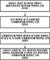
도 1은 본 발명의 일실시예에 따른 시계열 영상 분석방법에 대한 순서도이다.
도 2는 본 발명의 일실시예에 따라 획득된 제1영상의 예시도면이다.
도 3a는 본 발명의 일실시예에 따라 획득된 조영제를 넣기 전의 제2영상의 예시도면이다.
도 3b는 본 발명의 일실시예에 따라 획득된 조영제가 동맥을 통과할 때 제2영상의 예시도면이다.
도 3c는 본 발명의 일실시예에 따라 획득된 조영제가 정맥을 통과 할 때 제2영상의 예시도면이다.
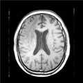
도 4는 본 발명의 일실시예에 따른 MR장비에 의해 획득된 제1영상의 예시도면이다.
도 5는 본 발명의 일실시예에 따른 MR장비에 의해 획득된 제2영상의 예시도면이다.
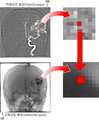
도 6는 본 발명의 일실시예에 따른 제1영상의 각 픽셀에 시계열데이터를 매칭하는 예시도면이다.
도 7는 본 발명의 일실시예에 따른 시계열데이터 그래프의 예시도면이다.
도 8은 본 발명의 일실시예에 따른 DSA영상의 예시도면이다.
도 9은 본 발명의 일실시예에 따라 컬러맵 생성을 위해 각 픽셀에 조영제 최대시점 수치데이터를 획득하는 예시도면이다.
도 10은 본 발명의 일실시예에 따라 각 픽셀에 대한 수치데이터를 대응하는 색상으로 변환하여 컬러맵을 생성하는 예시도면이다.1 is a flowchart illustrating a time-series image analysis method according to an embodiment of the present invention.
2 is an exemplary diagram of a first image acquired in accordance with an embodiment of the present invention.
FIG. 3A is an exemplary view of a second image obtained before incorporating the contrast agent obtained according to an embodiment of the present invention. FIG.
FIG. 3B is an illustration of a second image when the contrast agent acquired in accordance with an embodiment of the present invention passes through an artery. FIG.
3C is an exemplary illustration of a second image when the contrast agent acquired in accordance with one embodiment of the present invention passes through a vein.
4 is an exemplary view of a first image acquired by an MR device according to an embodiment of the present invention.
5 is an exemplary diagram of a second image acquired by an MR device according to an embodiment of the present invention.
6 is an exemplary diagram for matching time series data to each pixel of a first image according to an embodiment of the present invention.
7 is an exemplary diagram of a time series data graph according to an embodiment of the present invention.
8 is an exemplary diagram of a DSA image according to an embodiment of the present invention.
FIG. 9 is an exemplary diagram for obtaining contrast agent maximum point numerical data for each pixel for color map generation in accordance with an embodiment of the present invention.
10 is an exemplary diagram for generating a color map by converting numeric data for each pixel into a corresponding color according to an embodiment of the present invention.
이하, 첨부된 도면을 참조하여 본 발명의 바람직한 실시예를 상세히 설명한다. 본 발명의 이점 및 특징, 그리고 그것들을 달성하는 방법은 첨부되는 도면과 함께 상세하게 후술되어 있는 실시예들을 참조하면 명확해질 것이다. 그러나 본 발명은 이하에서 게시되는 실시예들에 한정되는 것이 아니라 서로 다른 다양한 형태로 구현될 수 있으며, 단지 본 실시예들은 본 발명의 게시가 완전하도록 하고, 본 발명이 속하는 기술분야에서 통상의 지식을 가진 자에게 발명의 범주를 완전하게 알려주기 위해 제공되는 것이며, 본 발명은 청구항의 범주에 의해 정의될 뿐이다. 명세서 전체에 걸쳐 동일 참조 부호는 동일 구성 요소를 지칭한다.Hereinafter, preferred embodiments of the present invention will be described in detail with reference to the accompanying drawings. BRIEF DESCRIPTION OF THE DRAWINGS The advantages and features of the present invention and the manner of achieving them will become apparent with reference to the embodiments described in detail below with reference to the accompanying drawings. The present invention may, however, be embodied in many different forms and should not be construed as limited to the embodiments set forth herein. Rather, these embodiments are provided so that this disclosure will be thorough and complete, and will fully convey the scope of the invention to those skilled in the art. To fully disclose the scope of the invention to those skilled in the art, and the invention is only defined by the scope of the claims. Like reference numerals refer to like elements throughout the specification.
다른 정의가 없다면, 본 명세서에서 사용되는 모든 용어(기술 및 과학적 용어를 포함)는 본 발명이 속하는 기술분야에서 통상의 지식을 가진 자에게 공통적으로 이해될 수 있는 의미로 사용될 수 있을 것이다. 또 일반적으로 사용되는 사전에 정의되어 있는 용어들은 명백하게 특별히 정의되어 있지 않는 한 이상적으로 또는 과도하게 해석되지 않는다.Unless defined otherwise, all terms (including technical and scientific terms) used herein may be used in a sense commonly understood by one of ordinary skill in the art to which this invention belongs. Also, commonly used predefined terms are not ideally or excessively interpreted unless explicitly defined otherwise.
본 명세서에서 사용된 용어는 실시예들을 설명하기 위한 것이며 본 발명을 제한하고자 하는 것은 아니다. 본 명세서에서, 단수형은 문구에서 특별히 언급하지 않는 한 복수형도 포함한다. 명세서에서 사용되는 "포함한다(comprises)" 및/또는 "포함하는(comprising)"은 언급된 구성요소 외에 하나 이상의 다른 구성요소의 존재 또는 추가를 배제하지 않는다.The terminology used herein is for the purpose of illustrating embodiments and is not intended to be limiting of the present invention. In the present specification, the singular form includes plural forms unless otherwise specified in the specification. The terms " comprises "and / or" comprising "used in the specification do not exclude the presence or addition of one or more other elements in addition to the stated element.
본 명세서에서 혈관조영영상은, 혈관조영검사를 수행하는 과정에서 획득되는 영상 또는 화상을 의미한다. 혈관조영검사는 조영제를 주입하여 영상측정장비를 이용한 영상촬영방법을 통해 혈관의 영상을 획득하는 검사의 일종이다. 상기 영상촬영방법은 X선을 이용하는 X-ray 촬영, 컴퓨터 단층촬영(Computed Tomography; CT) 뿐만 아니라 자기공명영상(Magnetic Resonance Imaging; MRI)촬영 등을 포함할 수 있다. 혈관조영영상은 혈관조영 검사를 수행하기 위해 조영제를 주입한 후에 영상측정장비에 의해 획득된 영상뿐만 아니라, 조영제를 주입하기 전에 획득된 영상도 포함한다.In the present specification, an angiographic image means an image or an image obtained in the course of performing an angiographic examination. Angiography is a type of test that acquires images of blood vessels by injecting a contrast agent and using an image capturing method using the image measuring device. The imaging method may include X-ray imaging, computed tomography (CT) as well as Magnetic Resonance Imaging (MRI) imaging. The angiographic images include not only the images obtained by the image measuring device after injecting the contrast agent to perform the angiographic examination but also the images obtained before injecting the contrast agent.
본 명세서에서 컴퓨터는 연산처리를 수행하여 사용자에게 결과를 시각적으로 제시할 수 있는 다양한 장치들이 모두 포함된다. 예를 들어, 컴퓨터는 데스크 탑 PC, 노트북(Note Book) 뿐만 아니라 스마트폰(Smart phone), 태블릿 PC, 셀룰러폰(Cellular phone), 피씨에스폰(PCS phone; Personal Communication Service phone), 동기식/비동기식 IMT-2000(International Mobile Telecommunication-2000)의 이동 단말기, 팜 PC(Palm Personal Computer), 개인용 디지털 보조기(PDA; Personal Digital Assistant) 등도 해당될 수 있다. 또한, 컴퓨터는 혈관조영영상을 획득하거나 관찰하는 의료장비도 해당될 수 있다.In this specification, the computer includes all of various devices capable of performing computational processing to visually present results to a user. For example, the computer may be a smart phone, a tablet PC, a cellular phone, a personal communication service phone (PCS phone), a synchronous / asynchronous A mobile terminal of IMT-2000 (International Mobile Telecommunication-2000), a Palm Personal Computer (PC), a personal digital assistant (PDA), and the like. The computer may also be a medical device that acquires or observes an angiographic image.
도 1은 본 발명의 일실시예에 따른 시계열 영상 분석방법에 대한 순서도이다. 도 2는 본 발명의 일실시예에 따라 획득된 제1영상의 예시도면이다. 도 3은 본 발명의 일실시예에 따라 획득된 제2영상의 예시도면이다. 도 4는 본 발명의 일실시예에 따른 MR장비에 의해 획득된 제1영상의 예시도면이다. 도 5는 본 발명의 일실시예에 따른 MR장비에 의해 획득된 제2영상의 예시도면이다. 도 6는 본 발명의 일실시예에 따른 제1영상의 각 픽셀에 시계열데이터를 매칭하는 예시도면이다. 도 7는 본 발명의 일실시예에 따른 시계열데이터 그래프의 예시도면이다. 도 8은 본 발명의 일실시예에 따른 DSA영상의 예시도면이다. 도 9은 본 발명의 일실시예에 따른 컬러맵 생성을 위해 각 픽셀에 조영제 최대시점 수치데이터를 획득하는 예시도면이다. 도 10은 본 발명의 일실시예에 따라 각 픽셀에 대한 수치데이터를 대응하는 색상으로 변환하여 컬러맵을 생성하는 예시도면이다.1 is a flowchart illustrating a time-series image analysis method according to an embodiment of the present invention. 2 is an exemplary diagram of a first image acquired in accordance with an embodiment of the present invention. 3 is an exemplary diagram of a second image acquired in accordance with an embodiment of the present invention. 4 is an exemplary view of a first image acquired by an MR device according to an embodiment of the present invention. 5 is an exemplary diagram of a second image acquired by an MR device according to an embodiment of the present invention. 6 is an exemplary diagram for matching time series data to each pixel of a first image according to an embodiment of the present invention. 7 is an exemplary diagram of a time series data graph according to an embodiment of the present invention. 8 is an exemplary diagram of a DSA image according to an embodiment of the present invention. FIG. 9 is an exemplary diagram for obtaining contrast medium maximum-point numerical data for each pixel for color map generation according to an embodiment of the present invention. 10 is an exemplary diagram for generating a color map by converting numeric data for each pixel into a corresponding color according to an embodiment of the present invention.
도 1 내지 도 10에는 제1영상의 프레임(100); 제2영상의 프레임(200); 제2영상에서 획득된 시계열데이터(300); 조영제 도착시점 표지(310); 및 DSA영상의 프레임(400)이 도시된다.1 to 10 show a
이하, 도면을 참조하여 본 발명의 실시예들에 따른 시계열 영상 분석방법 및 분석 프로그램에 대해 설명하기로 한다.Hereinafter, a time-series image analysis method and an analysis program according to embodiments of the present invention will be described with reference to the drawings.
도 1은 본 발명의 일실시예에 따른 시계열 영상 분석방법에 대한 순서도이다.1 is a flowchart illustrating a time-series image analysis method according to an embodiment of the present invention.
도 1을 참조하면, 본 발명의 일실시예에 따른 시계열 영상 분석방법은, 고해상도 영상인 제1영상(100)과 저해상도 영상인 제2영상(200)을 획득하는 단계(S100); 상기 제2영상(200) 내 각 지점에 대한 시계열데이터(300)를 획득하는 단계(S200); 상기 시계열데이터(300)를 획득한 상기 제2영상(200) 내 지점에 대응하는 상기 제1영상(100) 내 각 지점에 상기 시계열데이터(300)를 매칭하는 단계(S300); 및 사용자가 선택한 상기 제1 또는 제2영상(200)의 특정지점에 상응하는 좌표데이터를 수신하여, 상기 특정지점의 시계열데이터(300)를 제공하는 단계(S400);를 포함한다. 본 발명의 일 실시예에 따른 시계열 영상 분석방법을 순서대로 설명한다.Referring to FIG. 1, a time-series image analysis method according to an exemplary embodiment of the present invention includes acquiring a
고해상도 영상인 제1영상(100)과 저해상도 영상인 제2영상(200)을 획득한다(S100). 고해상도 영상(제1영상(100))은, 도 2에서와 같이, 많은 픽셀로 구성되어 공간적으로 선명하여 혈관 내 위치를 정확한 파악이 용이한 영상을 의미한다. 저해상도 영상(제2영상(200))은, 도 3에서와 같이, 고해상도 영상에 비해 비교적 해상도가 낮아(즉, 각 프레임당 영상을 구성하는 픽셀의 수가 적어) 선명도가 떨어지는 영상을 의미한다. 컴퓨터는 영상촬영장비에 제1영상(100) 및 제2영상(200) 촬영을 직접 요청하여 획득할 수 있고, 영상촬영장비에 의해 이미 촬영된 제1 및 제2영상(200)을 컴퓨터 내부 또는 외부서버에 저장해두고 분석을 수행할 때 불러올 수 있다.The
제1영상(100)과 제2영상(200)은 특정한 신체부위에 대하여 특정한 시간간격으로 촬영하여 획득된 하나 이상의 프레임으로 구성될 수 있다. 제1영상(100)의 획득된 프레임 개수는 상기 제2영상(200)의 획득된 프레임 개수보다 적을 수 있다. 예를 들어, 시계열데이터(300)를 제공받을 혈관 내 위치 선택을 위해서만 고해상도 영상을 사용하는 경우, 컴퓨터는 프레임 개수가 하나인 고해상도 영상(제1영상(100))을 획득하고 특정한 시간간격으로 복수의 프레임을 포함한 저해상도 영상(제2영상(200))을 획득할 수 있다. 또한, 컴퓨터는 사용자로부터 제1영상(100)과 제2영상(200)의 프레임 개수 비율을 설정받아서, 각각 특정한 시간간격으로 복수의 프레임을 촬영한 제1영상(100)과 제2영상(200)을 획득할 수 있다.The
또한, 컴퓨터는 짧은 시간 간격으로 제2영상(200)의 프레임을 획득하면서 특정한 시점에는 제2영상(200) 대신 제1영상(100)을 획득할 수 있다. 이를 통해, 컴퓨터가 제1영상(100)과 제2영상(200)을 획득하는 시간이 짧아질 수 있다.In addition, the computer may acquire the
고해상도 영상 또는 저해상도 영상과 같은 의료영상은, CT, X-ray, MRI와 같은 의료영상 취득장치에 부합하는 조영제를 주사한 후 의료영상 취득장치를 이용하여 획득된 혈류영상일 수 있다. CT와 X-ray 등 방사선을 사용하는 장치로 촬영하는 경우, 방사선량의 조절을 통해 해상도가 상이한 혈관조영영상(즉, 제1영상(100) 및 제2영상(200))을 획득할 수 있다. 즉, 컴퓨터는 방사선(X선)량을 높이면 고해상도 혈관조영영상(제1영상(100))을 획득할 수 있고, 방사선(X선)량을 낮추면 저해상도 혈관조영영상(제2영상(200))을 획득할 수 있다. 이 때, 고해상도 혈관조영영상을 짧은 시간간격으로 획득하고자 방사선량을 높이면, 환자의 방사선 노출량이 높아져 환자의 정상세포가 손상되는 등의 문제를 야기할 수 있다.A medical image such as a high-resolution image or a low-resolution image may be a blood flow image acquired by using a medical image acquisition device after injecting a contrast agent conforming to a medical image acquisition device such as CT, X-ray, or MRI. When capturing an image using a device using radiation such as CT and X-ray, an angiographic image (i.e., the
MR 장비를 사용하여 조영영상을 촬영하는 경우, 컴퓨터는 T1 강조 영상과 같은 공간적으로 고해상도인 영상(제1영상(100))을 획득할 수 있고, EPI(Echo Planar Image), DCE(Dynamic Contrast Enhanced, 역동적 조영증강) 영상 등과 같은 저해상도이지만 프레임 수가 많은 영상(제2영상(200))을 획득할 수 있다. 또한, MR장비를 이용한 동일한 촬영방식에서도 프레임당 포함되는 픽셀 수의 차이에 의해 고해상도 영상과 저해상도 영상을 획득할 수 있다. MR장비는 방사선을 활용하지 않으므로 고해상도 조영영상 촬영 시 방사선 과다 노출의 문제는 발생하지 않지만, 촬영시간이 과다하게 소요되는 문제가 발생할 수 있다. 즉, MR영상 촬영은 프레임 수와 프레임 내의 픽셀 수에 비례하여서 공간적으로 고해상도이면서 시간적으로도 고해상도인(즉, 시간간격이 조밀한) 영상을 획득하기 위해서는 촬영시간이 매우 오래 걸리게 된다, 따라서, 컴퓨터가 MR장비로 획득한 도 4와 같은 공간적으로 조밀한 고해상도 조영영상과 도 5와 같은 시간적으로 조밀한 저해상도 조영영상을 각각 획득한 후 동기화를 수행함으로써 해결할 수 있다.When imaging a contrast image using an MR device, the computer can acquire a spatially high-resolution image (first image 100) such as a T1-weighted image, and can acquire an echo planar image (EPI), a dynamic contrast enhanced (Dynamic image enhancement) images), but a large number of frames (second image 200) can be acquired. In addition, high resolution images and low resolution images can be obtained by the difference in the number of pixels included per frame even in the same imaging method using the MR apparatus. Since the MR device does not utilize the radiation, there is no problem of overexposure during high-resolution imaging, but it takes much time to shoot. That is, the MR imaging takes a very long time to acquire an image having a high spatial resolution and a high temporal resolution (i.e., a tight time interval) in proportion to the number of frames and the number of pixels in the frame. Therefore, Resolution high-resolution contrast image as shown in FIG. 4 and a low-resolution contrast image as shown in FIG. 5, respectively, and then performing synchronization.
또한, 고해상도 영상 또는 저해상도 영상과 같은 의료영상은, 상이한 방식으로 영상이 촬영되어 해상도 차이가 있는 MR영상일 수 있다. 예를 들어, 뇌의 기능에 대해 촬영하는 MR영상 촬영방식 중 기능적 MR영상(Functional MRI)은 프레임 하나당 촬영시간이 매우 짧아 해상도가 매우 떨어지는 방식이다. 따라서, 기능적 MR영상만으로 뇌와 같은 신체부위의 구조 또는 위치를 정확하게 판별하기 어려움이 있다. 따라서 공간적 식별력이 높은 고해상도의 구조적 MR영상을 획득하여, 복수 프레임의 저해상도 기능적 MR영상과 동기화하여 시계열 분석을 수행할 수 있다.In addition, a medical image such as a high-resolution image or a low-resolution image may be an MR image in which the image is photographed in a different manner and has a resolution difference. For example, Functional MRI (MR imaging), which takes images of brain functions, has a very short resolution time per frame. Therefore, it is difficult to accurately determine the structure or position of a body part such as the brain by functional MR imaging only. Therefore, it is possible to acquire a high-resolution structural MR image having high spatial discrimination power and perform time-series analysis in synchronization with low-resolution functional MR images of a plurality of frames.
컴퓨터는 상기 제2영상(200)의 프레임을 시간순서대로 분석하여 각 지점에 대한 시계열데이터(300)를 획득한다(S200). 상기 시계열데이터(300)는 컴퓨터가 제2영상의 프레임 내 각 지점에 대응하는 픽셀을 분석하여 인식한 색상, 밝기 등의 변화에 대한 수치데이터를 의미한다.The computer analyzes the frames of the
예를 들어, 상기 영상이 조영제를 주사하여 촬영한 혈류영상(즉, 혈관조영영상)인 경우, 시계열데이터는 특정시간 간격으로 획득된 제2영상(200) 프레임을 통해 측정된, 각 지점의 시간별 조영제에 의해 증강된 신호의 측정량 데이터일 수 있다. 혈관조영영상은 각 프레임마다 조영제에 의해 특정 영역이 증강된 2차원 영상을 포함하고 있다. 즉, 조영제를 주사하기 전에는, 도 3a에서와 같이, 조영 증강된 혈관영역이 존재하지 않다가, 동맥으로 조영제가 주사되면, 도 3b에서와 같이, 동맥영역이 밝아졌다가 시간이 흐름에 따라 조영제가 혈류와 함께 정맥쪽으로 이동하면서, 도 3c에서와 같이 정맥영역이 밝아지게 된다. 컴퓨터는 각 프레임 내에서 사용자가 선택한 특정한 지점(즉, 특정한 좌표)에 대응하는 밝기값을 추출한다. 상기 컴퓨터는 상기 추출된 밝기값을 각 프레임이 획득된 시간 순서에 따라 시계열데이터로 생성할 수 있다. 예를 들어, 혈관조영영상의 총 프레임 수가 n개인 경우, 1*N의 행렬을 생성하여 추출한 밝기 값을 순서대로 상기 행렬 내에 입력할 수 있다. 상기 컴퓨터는 상기 행렬 데이터를 바탕으로 그래프를 생성(plot)하는 등의 시계열 분석을 수행할 수 있다.For example, when the image is a blood flow image (i.e., an angiogram image) taken by scanning the contrast agent, the time series data may include time-series data measured through a
컴퓨터는 시계열데이터(300)를 획득한 제2영상(200) 내 지점에 대응하는 제1영상(100) 내 각 지점에 시계열데이터(300)를 매칭한다(S300). 컴퓨터는 시계열데이터(300)를 획득한 제2영상(200) 내 지점과 동일한 혈관 내 위치에 해당하는 제1영상(100)의 지점을 파악하고, 제1영상(100)의 지점에 각 시계열데이터(300)를 매칭한다. 즉, 컴퓨터는 동일시점에 해당하는 제1영상(100)과 제2영상(200)의 공간좌표 간 매칭을 수행한다.The computer matches the
예를 들어, 도 6에 도시된 바와 같이, 컴퓨터는 제2영상(200) 내 각 픽셀의 시계열데이터(300)를 제2영상(200) 내 픽셀에 대응하는 제1영상(100) 내 복수의 픽셀에 매칭할 수 있다. 즉, 컴퓨터는 저해상도인 제2영상(200)의 하나의 픽셀이 포함하는 복수의 제1영상(100)의 픽셀에 상기 제2영상(200) 픽셀에서 획득된 시계열데이터(300)를 매칭할 수 있다. 다만, 제2영상(200)에서 획득된 시계열데이터(300)를 제1영상(100)에 매칭하는 방법은 이에 한정되지 아니하고, 제1영상(100)과 제2영상(200)의 동일 지점에 동일한 시계열데이터(300)가 적용되도록 하는 다양한 방식이 적용될 수 있다.6, the computer may convert the
사용자가 선택한 제1 또는 제2영상(200)의 특정지점에 상응하는 좌표데이터를 수신하여, 상기 특정지점의 시계열데이터(300)를 제공한다(S400). 컴퓨터는 의료진과 같은 사용자로부터 제1 또는 제2영상(200)의 특정지점 좌표데이터를 입력받는다. 예를 들어, 컴퓨터가 마우스와 같은 입력수단을 사용하는 경우, 사용자가 마우스 커서를 특정지점 위에 배치(마우스오버; Mouseover)하면, 컴퓨터는 커서가 위치한 특정지점을 선택한 지점으로 판단하여 특정지점의 좌표를 획득할 수 있다. 또한, 컴퓨터가 터치스크린을 구비한 디바이스인 경우, 컴퓨터는 사용자로부터 화면의 제1 또는 제2영상(200)의 특정지점을 터치하면, 컴퓨터는 터치된 특정지점을 선택지점으로 판단하여 특정지점의 좌표를 획득할 수 있다.And receives the coordinate data corresponding to the specific point of the first or
그 후, 컴퓨터는 선택된 좌표데이터에 대응하는 시계열데이터(300)를 제공한다. 예를 들어, 컴퓨터는 사용자에 의해 선택된 제1 또는 제2영상(200) 내 특정한 픽셀에 대응하는 시계열데이터(300)를 표시할 수 있다. 컴퓨터는 시계열데이터(300)를 표 형태 또는 그래프 형태로 제공할 수 있다. 예를 들어, 도 7에서와 같이, CT 또는 X선 촬영을 하는 경우, 컴퓨터는 제2영상(200)의 각 프레임을 획득한 시간에 대한 X선 흡수율 또는 투과율을 도시하여 시계열데이터(300)를 그래프 형태로 제공할 수 있다.Then, the computer provides
또한, 제1영상(100)과 제2영상(200)의 동일한 지점에 동일한 시계열데이터(300)가 매칭되므로, 컴퓨터는 사용자로부터 제1 또는 제2영상(200) 중 어떠한 영상 내에서 특정지점을 선택받아도 동일한 좌표데이터로 인식되며 동일한 시계열데이터(300)를 제공할 수 있다.Since the same
또한, 컴퓨터는 시계열데이터(300)를 분석하여 상기 각 지점의 조영제 도착시점 또는 최대시점을 인식할 수 있다. 예를 들어, 도 7에서와 같이, 컴퓨터는 특정지점의 시계열데이터(300) 분석을 통해 파악된 조영제가 도착한 시점을 세로선과 같은 특정표지(310)로 그래프상에 표시할 수 있다. 상기 조영제 도착시점 또는 최대시점은, 동맥 또는 정맥의 기형 혈관을 치료하는데 치료 전후의 혈류흐름 비교하는 데 활용될 수 있다. 의료진은 상기 조영제 도착시점 또는 최대시점의 인식을 통해 특정한 병변의 치료가 얼마나 잘 되었는가를 판단할 수 있는 지표로 활용할 수 있다.In addition, the computer may analyze the
또한, 상기 시계열데이터(300) 제공단계(S400)는, 상기 사용자로부터 선택된 특정지점에 대한 상기 조영제 도착시점 이후 특정시점의 제1 또는 제2영상(200)을 표시하는 단계;를 포함할 수 있다. 도 3a 내지 도 3c에 도시된 바와 같이, 동맥으로 조영제를 주입한 후 통과되는 혈관의 위치에 따라 조영증강에 의해 강조되는 부분이 달라지게 된다. 의료진이 혈관 검사 시 혈관의 상태를 시각적으로 더 잘 파악하기 위해서는, 컴퓨터가 사용자로부터 선택된 특정지점을 많은 양의 조영제가 통과하여 선명하게 인식될 수 있는 제1 또는 제2영상(200)의 프레임을 화면에 표시해줄 필요가 있다. 따라서 컴퓨터는 시계열데이터(300)를 바탕으로 선택된 특정지점을 통과하는 조영제 양이 특정기준 이상인 프레임을 추출하여 표시하도록 할 수 있다.The step of providing the
또한, 상기 획득된 제1 또는 제2영상(200)에서 조영된 혈관영역에서 추출된 DSA영상(400)인 제1추출영상 또는 제2추출영상을 생성하는 단계;를 더 포함할 수 있다. 즉, 사용자가 관심을 갖는 영역인 혈관만 세밀하게 관찰할 수 있도록, 컴퓨터는 조영제가 통과함에 따라 강조된 혈관영역만을 추출할 수 있다. 이를 위해 컴퓨터는 조영제가 주입된 후의 영상에서 조영제가 주입되기 전의 영상을 제외하여 임상적 진단을 하는데 불필요한 골격 등을 제외한 혈관영역만 추출한 영상을 생성할 수 있다. 이러한 혈관영역만 추출된 영상을 DSA(Digital Subtraction Angiography)영상이라고 한다. DSA영상(400)을 활용함에 따라, 의료진은 시계열데이터(300)를 확인하고자 하는 지점을 정확하게 선택할 수 있으며, 특정지점의 혈액 흐름(예를 들어, 혈액이 정상상태와 다른 곳으로 흘러나가는지 여부 등)을 정확하게 관찰할 수 있다.The method may further include generating a first extracted image or a second extracted image that is a
또한, 상기 매칭단계(S300)는, 특정기준에 따라 상기 제1영상(100)의 프레임과 상기 제2영상(200)의 프레임을 대응시키는 동기화하는 단계;를 포함할 수 있다. 상기 특정기준은 프레임의 개수가 상이한 제1영상(100)의 프레임과 제2영상(200)의 프레임 간의 매칭 규칙에 해당한다.The matching step S300 may include synchronizing a frame of the
예를 들어, 제1영상(100)의 복수의 프레임을 획득한 시간간격과 제2영상(200)의 복수의 프레임을 획득한 시간간격이 배수관계에 해당하는 경우, 컴퓨터는 제1영상(100)의 각 프레임에 대응되는 제2영상(200)의 프레임을 판단하여, 제1 또는 제2영상(200)의 프레임을 동기화할 수 있다. 또한, 컴퓨터는 제2영상(200)의 각 프레임을 대응시킬 제1영상(100)의 프레임을 설정할 수 있다. 즉, 제2영상(200)의 프레임 수에 비해 제1영상(100)의 프레임 수가 적으므로, 컴퓨터는 제1영상(100)의 각 프레임에 대응시킬 제2영상(200) 범위를 판단하여 대응시킬 수 있다. 일실시예로, 제1영상 내의 연속한 프레임이 제1프레임과 제2프레임인 경우, 컴퓨터는 제1프레임과 제2프레임이 각각 획득되는 시점의 중간시점을 기준시점으로 설정할 수 있다. 그 후, 컴퓨터는 제1프레임과 제2프레임의 획득시점 사이에 촬영된 제2영상 프레임 중에서 기준시점 이전에 획득된 프레임은 제1프레임에 매칭하고, 기준시점 이후에 획득된 프레임은 제2프레임에 매칭할 수 있다. 컴퓨터가 제2영상(200)의 복수의 프레임을 제1영상(100)의 프레임에 매칭하는 특정기준 또는 방식은 이에 한정되지 않고, 특정한 기준시점을 설정하여 프레임을 매칭하는 방식이 아닌 제1영상(100)의 특정 프레임에 대응되는 제2영상(200) 프레임의 개수를 바탕으로 매칭을 수행하는 방식 등의 다양한 방식을 적용할 수 있다.For example, when a time interval between acquiring a plurality of frames of the
이를 통해, 의료진이 제1영상(100) 또는 제2영상(200)의 특정한 프레임을 선택하는 경우, 다른 영상의 적절한 프레임(예를 들어, 제1영상(100)의 특정한 프레임을 선택한 경우, 제1영상(100)의 특정한 프레임이 획득된 시점에 대응되는 제2영상(200)의 프레임)을 함께 제공받을 수 있다. 또한, 사용자가 선택한 특정지점의 최적프레임(예를 들어, 조영제 통과량이 많아 혈관의 관찰이 용이한 프레임)을 자동으로 제공해주는 경우, 의료진은 제1 또는 제2영상(200) 중 어떠한 영상에서 특정지점을 선택하더라도 제1영상(100)과 제2영상(200)의 최적프레임을 함께 제공받을 수 있다. 따라서 의료진은 제1영상(100)과 제2영상(200)을 각각 조절하여야 하는 불편함을 해소할 수 있으며, 혈관조영영상을 이용하여 분석 또는 진단을 하는데 소요되는 시간을 줄일 수 있다.Accordingly, when the medical staff selects a specific frame of the
또한, 상기 제1 또는 제2영상(200)을 고정영상 또는 이동영상으로 설정하는 단계; 및 상기 고정영상과 상기 이동영상간의 오차를 최소화하는 이동영상의 위치를 결정하는 단계;를 더 포함할 수 있다. 뇌혈관 영역은 환자의 움직임이 적어서 촬영한 제1영상(100)과 제2영상(200)의 특정지점의 위치가 동일할 수 있지만, 다양한 원인(예를 들어, 호흡 등)에 의해 움직임이 발생하는 신체부위는 제1영상(100)과 제2영상(200)의 특정지점의 위치가 일치되지 않을 수 있다. 또한, 제1영상(100)과 제2영상(200)이 동시에 획득되지 않아 촬영 위치가 상이하거나 환자가 촬영 중에 움직이는 경우, 제1영상(100)과 제2영상(200) 내 특정지점의 위치가 일치되지 않을 수 있다. 따라서 이러한 경우, 컴퓨터는 제1영상(100)과 제2영상(200)을 정합하는 과정을 수행할 필요가 있다.Setting the first or
따라서 컴퓨터는 제1영상(100) 또는 제2영상(200)을 고정영상 또는 이동영상으로 설정하고, 고정영상과 이동영상이 제대로 정합되었는지 판단(즉, 이동영상의 위치가 적절한지 여부를 판단)하는 다양한 정합도 측정 방식을 통해 이동영상의 위치의 적절성을 판단하여 최적화된 위치로 이동영상을 이동시킬 수 있다. 상기 고정영상은, 영상정합의 기준이 되기 위해 특정한 위치에 고정되는 영상을 의미한다. 상기 이동영상은, 영상정합을 위해 고정영상에 대하여 적합한 위치로 이동하는 영상을 의미한다. 컴퓨터가 고정영상과 이동영상간의 정합도를 파악하는 방법으로는 고정영상 및 이동영상 내 동일 지점의 신호세기 차이의 절대값 또는 제곱값의 합을 통해 오차를 계산 방식, 상관계수, 상호정보량, 정규상호정보량 등의 유사성 척도를 측정하는 방식을 적용할 수 있다. 그 후, 컴퓨터는 계산된 정합도를 바탕으로 이동영상의 위치를 이동시킬 수 있다. 컴퓨터는 정확한 영상정합을 위해 정합도 판단 및 이동영상의 위치 이동을 여러 번 수행할 수 있다. 이를 통해, 제1영상(100)과 제2영상(200)의 정합이 수행되어 제1영상(100)에 시계열데이터(300)를 대응시키는 과정에서 오차가 생기는 것을 방지할 수 있다.Accordingly, the computer sets the
또한, 상기 제1 또는 제2영상(200)을 영상처리하여 노이즈를 제거하는 단계;를 더 포함할 수 있다. 컴퓨터는 제1영상(100) 또는 제2영상(200)에서 조영제 양을 정확히 파악하거나 혈관을 정확하게 관찰하기 위해, 컴퓨터는 제1 또는 제2영상(200)에 포함된 노이즈(Noise)를 제거할 필요가 있다. 컴퓨터는 노이즈 제거 방식으로 공간적 평활화(Spatial Smoothing) 또는 시간적 평활화(Temporal Smoothing)을 수행할 수 있다.The method may further include image processing the first or
공간적 평활화(Spatial Smoothing)는 제1 또는 제2영상(200)의 특정 프레임 내에서 발생한 노이즈 또는 오류를 보정하는 방법을 의미한다. 컴퓨터는 평균 필터(Mean filter), 가우시안 필터(Gaussian filter) 등의 필터를 이용해서 제1 또는 제2영상(200)의 각 프레임을 공간적 평활화(Spatial Smoothing)를 수행할 수 있다. 컴퓨터는 사용자로부터 평활화의 강도를 입력받을 수 있고, 자체 연산을 통해 적절한 평활화 강도를 결정할 수도 있다. 또한, 컴퓨터는 공간적 평활화(Spatial Smoothing) 과정에서 제1영상(100)과 제2영상(200)의 각 픽셀의 수치를 비교하여 적절한 값으로 보정을 수행할 수 있다. 시간적 평활화(Temporal Smoothing)는 제2영상(200)의 분석을 통해 획득된 특정한 픽셀의 시계열데이터(300)에 대한 보정을 의미한다. 컴퓨터는 이동 평균(Moving average)기법을 이용하거나 시계열데이터(300) 중에서 이상점(Outlier)에 해당하는 데이터를 제외하는 방식을 이용하여 시간적 평활화(Temporal Smoothing)를 수행할 수 있다. 이를 통해 비이상적인 데이터(예를 들어, 연속적인 혈액 흐름상에서 비이상적으로 불연속적인 시계열적 데이터 또는 공간상에서 인접영역과 비교하여 비이상적으로 상이한 픽셀)을 보정(노이즈 제거)하여, 추출되는 시계열데이터(300)의 정확도를 높여줄 수 있다.Spatial smoothing refers to a method of correcting noise or errors occurring in a specific frame of the first or
또한, 본 발명의 일실시예는 상기 시계열데이터를 분석하여 상기 조영제의 도착시점 또는 최대시점 중 어느 하나의 수치데이터를 획득하고, 상기 수치데이터에 대응하는 소정의 색상으로 각 픽셀이 변환된 컬러맵 영상을 생성하는 단계;를 더 포함할 수 있다. 먼저, 컴퓨터는 상기 시계열데이터를 분석하여 상기 조영제의 도착시점, 최대시점 등의 수치데이터를 획득할 수 있다. 그 후, 컴퓨터는 상기 수치데이터에 대응하는 소정의 색상으로 각 픽셀이 변환된 컬러맵 영상을 생성할 수 있다. 예를 들어, 도 9에서와 같이, 상기 컴퓨터는 특정한 분석결과에 관한 컬러맵 생성에 필요한 각 픽셀에 대응하는 수치데이터를 추출할 수 있다. 사용자가 조영제의 최대시점에 대한 컬러맵 생성을 원하는 경우, 컴퓨터는 각 픽셀에 대응하는 조영제의 최대시점 수치데이터를 획득할 수 있다. 그 후, 도 10에서와 같이, 컴퓨터는 미리 정해진 색상과 수치의 대응관계에 따라 상기 획득된 수치데이터에 상응하는 색상을 파악하고, 상기 파악된 색상을 각 픽셀에 적용하여 컬러맵을 생성할 수 있다.According to an embodiment of the present invention, the time-series data is analyzed to acquire numerical data of any one of an arrival time point and a maximum time point of the contrast agent, and a color map in which each pixel is converted into a predetermined color corresponding to the numeric data And generating an image based on the image data. First, the computer may analyze the time series data to obtain numerical data such as an arrival time and a maximum time point of the contrast agent. Thereafter, the computer can generate a color map image in which each pixel is converted to a predetermined color corresponding to the numerical data. For example, as shown in FIG. 9, the computer can extract numeric data corresponding to each pixel necessary for generating a color map relating to a specific analysis result. If the user wishes to generate a color map for the maximum point in time of the contrast agent, the computer may obtain maximum point value data of the contrast agent corresponding to each pixel. Then, as shown in FIG. 10, the computer can recognize a color corresponding to the obtained numerical data according to a correspondence relationship between a predetermined color and a numerical value, and apply the recognized color to each pixel to generate a color map have.
이상에서 전술한 본 발명의 일 실시예에 따른 시계열 영상 분석 방법은, 하드웨어인 컴퓨터와 결합되어 실행되기 위해 프로그램(또는 어플리케이션)으로 구현되어 매체에 저장될 수 있다.As described above, the time-series image analysis method according to an embodiment of the present invention can be implemented as a program (or application) to be executed in combination with a hardware computer and stored in a medium.
상기 전술한 프로그램은, 상기 컴퓨터가 프로그램을 읽어 들여 프로그램으로 구현된 상기 방법들을 실행시키기 위하여, 상기 컴퓨터의 프로세서(CPU)가 상기 컴퓨터의 장치 인터페이스를 통해 읽힐 수 있는 C, C++, JAVA, 기계어 등의 컴퓨터 언어로 코드화된 코드(Code)를 포함할 수 있다. 이러한 코드는 상기 방법들을 실행하는 필요한 기능들을 정의한 함수 등과 관련된 기능적인 코드(Functional Code)를 포함할 수 있고, 상기 기능들을 상기 컴퓨터의 프로세서가 소정의 절차대로 실행시키는데 필요한 실행 절차 관련 제어 코드를 포함할 수 있다. 또한, 이러한 코드는 상기 기능들을 상기 컴퓨터의 프로세서가 실행시키는데 필요한 추가 정보나 미디어가 상기 컴퓨터의 내부 또는 외부 메모리의 어느 위치(주소 번지)에서 참조되어야 하는지에 대한 메모리 참조관련 코드를 더 포함할 수 있다. 또한, 상기 컴퓨터의 프로세서가 상기 기능들을 실행시키기 위하여 원격(Remote)에 있는 어떠한 다른 컴퓨터나 서버 등과 통신이 필요한 경우, 코드는 상기 컴퓨터의 통신 모듈을 이용하여 원격에 있는 어떠한 다른 컴퓨터나 서버 등과 어떻게 통신해야 하는지, 통신 시 어떠한 정보나 미디어를 송수신해야 하는지 등에 대한 통신 관련 코드를 더 포함할 수 있다.The above-described program may be stored in a computer-readable medium such as C, C ++, JAVA, machine language, or the like that can be read by the processor (CPU) of the computer through the device interface of the computer, And may include a code encoded in a computer language of the computer. Such code may include a functional code related to a function or the like that defines necessary functions for executing the above methods, and includes a control code related to an execution procedure necessary for the processor of the computer to execute the functions in a predetermined procedure can do. Further, such code may further include memory reference related code as to whether the additional information or media needed to cause the processor of the computer to execute the functions should be referred to at any location (address) of the internal or external memory of the computer have. Also, when the processor of the computer needs to communicate with any other computer or server that is remote to execute the functions, the code may be communicated to any other computer or server remotely using the communication module of the computer A communication-related code for determining whether to communicate, what information or media should be transmitted or received during communication, and the like.
상기 저장되는 매체는, 레지스터, 캐쉬, 메모리 등과 같이 짧은 순간 동안 데이터를 저장하는 매체가 아니라 반영구적으로 데이터를 저장하며, 기기에 의해 판독(reading)이 가능한 매체를 의미한다. 구체적으로는, 상기 저장되는 매체의 예로는 ROM, RAM, CD-ROM, 자기 테이프, 플로피디스크, 광 데이터 저장장치 등이 있지만, 이에 제한되지 않는다. 즉, 상기 프로그램은 상기 컴퓨터가 접속할 수 있는 다양한 서버 상의 다양한 기록매체 또는 사용자의 상기 컴퓨터상의 다양한 기록매체에 저장될 수 있다. 또한, 상기 매체는 네트워크로 연결된 컴퓨터 시스템에 분산되어, 분산방식으로 컴퓨터가 읽을 수 있는 코드가 저장될 수 있다.The medium to be stored is not a medium for storing data for a short time such as a register, a cache, a memory, etc., but means a medium that semi-permanently stores data and is capable of being read by a device. Specifically, examples of the medium to be stored include ROM, RAM, CD-ROM, magnetic tape, floppy disk, optical data storage, and the like, but are not limited thereto. That is, the program may be stored in various recording media on various servers to which the computer can access, or on various recording media on the user's computer. In addition, the medium may be distributed to a network-connected computer system so that computer-readable codes may be stored in a distributed manner.
상기와 같은 본 발명에 따르면, 아래와 같은 다양한 효과들을 가진다.According to the present invention as described above, the following various effects are obtained.
첫째, 공간적으로 고해상도의 영상(high spatial resolution image)과 시간적으로 조밀한 프레임의 영상(high temporal resolution image)을 동시에 사용함으로써 분석을 위한 정보의 양을 늘릴 수 있다. 즉, 고해상도 영상 촬영을 하여 시간적으로 조밀한 시계열데이터를 얻지 못했던 기존 방식과 달리, 고해상도 영상을 관찰하면서 저해상도 영상 분석을 통해 얻은 시간적으로 조밀한 시계열데이터를 확인할 수 있어 환자 상태에 대한 정확한 분석을 할 수 있는 효과가 있다.First, the amount of information for analysis can be increased by simultaneously using a high spatial resolution image and a high temporal resolution image. In other words, unlike the conventional method, which does not acquire time series dense time series data by taking a high resolution image, it is possible to confirm the time series dense time data obtained from the low resolution image analysis while observing the high resolution image, There is an effect that can be.
둘째, 고해상도 영상을 통해 시계열데이터를 제공받고자 하는 특정지점을 세밀하게 확인하고 정확히 선택할 수 있어, 사용자는 원하는 지점(Region of Interest; ROI)에 대한 적절한 정보를 획득할 수 있다.Second, it is possible to precisely check and select a specific point to receive the time series data through the high-resolution image, so that the user can obtain appropriate information on the desired region of interest (ROI).
셋째, 의료진이 공간적으로 고해상도인 영상과 조밀한 시간 간격의 시계열데이터를 함께 확인하면서 진단을 할 수 있어, 의료진이 진단을 하는데 소요되는 시간을 줄일 수 있다. 즉, 의료진이 간편하게 의료영상의 시계열 분석을 수행할 수 있어 진단 결과가 나오는 시간을 줄일 수 있다.Third, the medical staff can make a diagnosis by checking the time-series data of the spatially high-resolution image and the dense time interval, and the time required for the diagnosis by the medical staff can be reduced. That is, the medical staff can easily perform the time series analysis of the medical image, thereby reducing the time for the diagnosis result.
넷째, 방사선을 이용하는 X선 촬영 또는 CT촬영의 경우, 조밀한 시계열데이터 획득을 위해 방사선을 적게 사용하여 촬영하는 저해상도 영상을 이용하므로, 환자에게 발생할 수 있는 방사선 피해를 줄일 수 있는 효과가 있다.Fourthly, in the case of X-ray or CT using radiography, low-resolution images are obtained by using less radiation to acquire dense time series data, thereby reducing the radiation damage that can be caused to the patient.
다섯째, MRI촬영을 통해 영상을 획득하는 경우, 복수의 프레임을 획득하는데 소요되는 시간을 줄일 수 있는 효과가 있다. 이에 따라 많은 프레임 수의 고해상도 영상을 촬영하기 위해 환자들이 소비하는 시간을 줄일 수 있으며, 병원은 촬영시간을 줄여서 많은 환자의 검사를 진행할 수 있는 효과가 있다.Fifth, when acquiring an image through MRI, there is an effect of reducing the time required to acquire a plurality of frames. Therefore, it is possible to reduce the time consumed by the patients in order to capture a high-resolution image of a large number of frames, and the hospital can reduce the shooting time, and thus it is possible to carry out the examination of many patients.
여섯째, 제1영상 또는 제2영상이 동기화되어서 사용자에 의한 특정 영상의 프레임 변경에 따라 다른 영상도 함께 프레임이 변경될 수 있어, 의료진은 제1영상과 제2영상을 각각 조절하여야 하는 불편함을 해소할 수 있으며, 혈관조영영상을 이용하여 분석 또는 진단을 하는데 소요되는 시간을 줄일 수 있다.Sixth, since the first image or the second image is synchronized, the frame can be changed together with other images according to the frame change of the specific image by the user, so that the medical staff has to adjust the first image and the second image respectively And it is possible to reduce the time required for analysis or diagnosis using an angiographic image.
일곱째, 임상적으로 필요한 조영제의 도착시점, 최대시점을 자동으로 찾아서 의료진에게 제공해주므로, 의료진이 임상적 진단을 간편하게 수행할 수 있는 효과를 제공할 수 있다.Seventh, since the arrival time and maximum time point of the clinically necessary contrast agent are automatically detected and provided to the medical staff, it is possible for the medical staff to perform the clinical diagnosis easily.
여덟째, 제1영상과 제2영상의 위치가 일치되지 않는 경우, 제1영상과 제2영상의 정합을 자동으로 수행하여 제1영상에 시계열데이터를 대응시키는 과정에서 오차가 생기는 것을 방지할 수 있다. 또한, 제1영상과 제2영상을 촬영 시 환자 위치에 차이가 발생해도 자체적으로 보정을 수행할 수 있어, 혈관조영영상 촬영을 간편하게 해주는 효과가 있다.Eighth, when the positions of the first image and the second image are not matched, matching of the first image and the second image is automatically performed to prevent an error in the process of mapping the time-series data to the first image . Further, even if there is a difference in the position of the patient when photographing the first image and the second image, the correction can be performed by itself, which makes it easy to take an angiographic image.
이상 첨부된 도면을 참조하여 본 발명의 실시예들을 설명하였지만, 본 발명이 속하는 기술분야에서 통상의 지식을 가진 자는 본 발명이 그 기술적 사상이나 필수적인 특징을 변경하지 않고서 다른 구체적인 형태로 실시될 수 있다는 것을 이해할 수 있을 것이다. 그러므로 이상에서 기술한 실시예들은 모든 면에서 예시적인 것이며 한정적이 아닌 것으로 이해해야만 한다.While the present invention has been described in connection with what is presently considered to be practical exemplary embodiments, it is to be understood that the invention is not limited to the disclosed embodiments, but, on the contrary, You will understand. It is therefore to be understood that the above-described embodiments are illustrative in all aspects and not restrictive.
100 : 제1영상의 프레임200: 제2영상의 프레임
300 : 제2영상에서 획득된 시계열데이터
310 : 조영제 도착시점 표지
400 : DSA영상의 프레임100: frame of the first image 200: frame of the second image
300: time series data obtained from the second image
310: Signs on the arrival of contrast media
400: frame of DSA image
Claims (14)
Translated fromKorean상기 제2영상 내 각 지점에 대한 시계열데이터를 획득하는 단계;
상기 시계열데이터를 획득한 상기 제2영상 내 지점에 대응하는 상기 제1영상 내 각 지점에 상기 시계열데이터를 매칭하는 단계; 및
사용자가 선택한 상기 제1 또는 제2영상의 특정지점에 상응하는 좌표데이터를 수신하여, 상기 특정지점의 시계열데이터를 제공하는 단계;를 포함하는, 시계열 영상 분석방법.
Obtaining a first image as a high-resolution image and a second image as a low-resolution image;
Obtaining time series data for each point in the second image;
Matching the time series data to each point in the first image corresponding to a point in the second image obtained by the time series data; And
And receiving coordinate data corresponding to a specific point of the first or second image selected by the user and providing time series data of the specific point.
상기 영상은,
특정한 영상취득장치에 부합하는 조영제를 주입한 후 상기 영상취득장치를 통해 획득된 혈류영상인 것을 특징으로 하는, 시계열 영상 분석방법.
The method according to claim 1,
Wherein the image includes:
Wherein the blood flow image acquired by the image acquisition device after injecting a contrast agent corresponding to a specific image acquisition device is obtained.
상기 시계열데이터는,
상기 제2영상의 특정시간 간격으로 획득된 프레임을 통해 측정된, 각각의 상기 특정지점의 시간별 조영제에 의해 증강된 신호의 측정량 데이터인 것을 특징으로 하는, 시계열 영상 분석방법.
3. The method of claim 2,
The time-
Wherein the measurement data of the signal enhanced by the time-specific contrast agent of each of the specific points measured through the frame obtained at a specific time interval of the second image.
상기 영상은 자기공명영상이며,
상기 제1영상은 자기공명영상 장치를 통해 고해상도로 촬영된 구조적 자기공명영상이고,
상기 제2영상은 시계열적인 복수의 프레임이 획득된 저해상도의 기능적 자기공명영상인, 시계열 영상 분석방법.
The method according to claim 1,
Wherein the image is a magnetic resonance image,
Wherein the first image is a structural MRI image photographed at a high resolution through a MRI apparatus,
And the second image is a low-resolution functional magnetic resonance image obtained by obtaining a plurality of frames in a time series.
상기 제1영상의 획득된 프레임 개수가 상기 제2영상의 획득된 프레임 개수보다 적은 것을 특징으로 하는, 시계열 영상 분석방법.
5. The method according to any one of claims 1 to 4,
Wherein the number of acquired frames of the first image is less than the number of acquired frames of the second image.
상기 매칭단계는,
특정기준에 따라 상기 제1영상의 프레임과 상기 제2영상의 프레임을 대응시켜 동기화하는 단계;를 포함하는, 시계열 영상 분석방법.
5. The method according to any one of claims 1 to 4,
The matching step comprises:
And synchronizing the frame of the first image and the frame of the second image in correspondence with each other according to a specific criterion.
상기 획득된 제1 또는 제2영상에서 조영된 영역에서 추출된 DSA영상인 제1추출영상 또는 제2추출영상을 생성하는 단계;를 더 포함하는, 시계열 영상 분석방법.
4. The method according to any one of claims 1 to 3,
And generating a first extracted image or a second extracted image that is a DSA image extracted from the obtained first or second image region.
상기 시계열데이터를 분석하여 상기 각 지점의 조영제 도착시점 또는 최대시점을 표시하는 단계;를 더 포함하는, 시계열 영상 분석방법.
4. The method according to any one of claims 1 to 3,
And analyzing the time series data to display a contrast agent arrival point or a maximum point of time at each of the points.
상기 시계열데이터 제공단계는,
상기 사용자로부터 선택된 상기 특정지점에 대한 조영제 도착시점 이후 특정시점의 제1 또는 제2영상을 표시하는 단계;를 포함하는, 시계열 영상 분석방법.
9. The method of claim 8,
The time-series data providing step may include:
And displaying a first or second image at a specific time point after the contrast agent arrival point for the specific point selected by the user.
상기 제1 또는 제2영상을 고정영상 또는 이동영상으로 설정하는 단계; 및
상기 고정영상과 상기 이동영상간의 오차를 최소화하는 상기 이동영상의 위치를 결정하는 단계;를 더 포함하는, 시계열 영상 분석방법.
5. The method according to any one of claims 1 to 4,
Setting the first or second image as a fixed image or a moving image; And
And determining a position of the moving image that minimizes an error between the fixed image and the moving image.
상기 제1 또는 제2영상을 영상처리하여 노이즈를 제거하는 단계;를 더 포함하는, 시계열 영상 분석방법.
5. The method according to any one of claims 1 to 4,
And removing noise by image processing the first or second image.
상기 시계열데이터 매칭단계는,
상기 제2영상 내 각 픽셀의 시계열데이터를 상기 제2영상 내 픽셀에 대응하는 상기 제1영상 내 복수의 픽셀에 매칭하는 것을 특징으로 하는, 시계열 영상 분석방법.
5. The method according to any one of claims 1 to 4,
Wherein the time series data matching step comprises:
Wherein the time series data of each pixel in the second image is matched to a plurality of pixels in the first image corresponding to the pixels in the second image.
상기 시계열데이터를 분석하여 조영제의 도착시점 또는 최대시점 중 어느 하나의 수치데이터를 획득하고, 상기 수치데이터에 대응하는 소정의 색상으로 각 픽셀이 변환된 컬러맵 영상을 생성하는 단계;를 더 포함하는, 시계열 영상 분석방법.
5. The method according to any one of claims 1 to 4,
Analyzing the time series data to obtain numerical data of any one of an arrival time point and a maximum time point of the contrast agent and generating a color map image in which each pixel is converted into a predetermined color corresponding to the numerical data; , Time series image analysis method.
Priority Applications (1)
| Application Number | Priority Date | Filing Date | Title |
|---|---|---|---|
| KR1020150041305AKR101628723B1 (en) | 2015-03-25 | 2015-03-25 | Method and program for time series image analysis |
Applications Claiming Priority (1)
| Application Number | Priority Date | Filing Date | Title |
|---|---|---|---|
| KR1020150041305AKR101628723B1 (en) | 2015-03-25 | 2015-03-25 | Method and program for time series image analysis |
Publications (1)
| Publication Number | Publication Date |
|---|---|
| KR101628723B1true KR101628723B1 (en) | 2016-06-09 |
Family
ID=56139072
Family Applications (1)
| Application Number | Title | Priority Date | Filing Date |
|---|---|---|---|
| KR1020150041305AExpired - Fee RelatedKR101628723B1 (en) | 2015-03-25 | 2015-03-25 | Method and program for time series image analysis |
Country Status (1)
| Country | Link |
|---|---|
| KR (1) | KR101628723B1 (en) |
Cited By (4)
| Publication number | Priority date | Publication date | Assignee | Title |
|---|---|---|---|---|
| CN114202538A (en)* | 2021-12-17 | 2022-03-18 | 深圳市铱硙医疗科技有限公司 | Brain image analysis method and system |
| KR20230168230A (en)* | 2022-06-03 | 2023-12-13 | 전남대학교산학협력단 | Method and apparatus for detecting position of biopsy needle in medical diagnostic image |
| CN119359687A (en)* | 2024-10-28 | 2025-01-24 | 东南大学 | A method for analyzing coronary artery stenosis using DSA based on matching degree measurement |
| WO2025170247A1 (en)* | 2024-02-05 | 2025-08-14 | 재단법인 아산사회복지재단 | Apparatus and method for detecting lymphatic contraction signal in real time |
Citations (4)
| Publication number | Priority date | Publication date | Assignee | Title |
|---|---|---|---|---|
| US6056691A (en)* | 1998-06-24 | 2000-05-02 | Ecton, Inc. | System for collecting ultrasound imaging data at an adjustable collection image frame rate |
| JP2004040422A (en)* | 2002-07-02 | 2004-02-05 | Monolith Co Ltd | Image processing method and apparatus |
| JP2007000205A (en)* | 2005-06-21 | 2007-01-11 | Sanyo Electric Co Ltd | Image processing apparatus, image processing method, and image processing program |
| JP2012217632A (en)* | 2011-04-08 | 2012-11-12 | Hitachi Medical Corp | Image diagnostic apparatus and image processing apparatus |
- 2015
- 2015-03-25KRKR1020150041305Apatent/KR101628723B1/ennot_activeExpired - Fee Related
Patent Citations (4)
| Publication number | Priority date | Publication date | Assignee | Title |
|---|---|---|---|---|
| US6056691A (en)* | 1998-06-24 | 2000-05-02 | Ecton, Inc. | System for collecting ultrasound imaging data at an adjustable collection image frame rate |
| JP2004040422A (en)* | 2002-07-02 | 2004-02-05 | Monolith Co Ltd | Image processing method and apparatus |
| JP2007000205A (en)* | 2005-06-21 | 2007-01-11 | Sanyo Electric Co Ltd | Image processing apparatus, image processing method, and image processing program |
| JP2012217632A (en)* | 2011-04-08 | 2012-11-12 | Hitachi Medical Corp | Image diagnostic apparatus and image processing apparatus |
Cited By (5)
| Publication number | Priority date | Publication date | Assignee | Title |
|---|---|---|---|---|
| CN114202538A (en)* | 2021-12-17 | 2022-03-18 | 深圳市铱硙医疗科技有限公司 | Brain image analysis method and system |
| KR20230168230A (en)* | 2022-06-03 | 2023-12-13 | 전남대학교산학협력단 | Method and apparatus for detecting position of biopsy needle in medical diagnostic image |
| KR102776812B1 (en) | 2022-06-03 | 2025-03-06 | 전남대학교산학협력단 | Method and apparatus for detecting position of biopsy needle in medical diagnostic image |
| WO2025170247A1 (en)* | 2024-02-05 | 2025-08-14 | 재단법인 아산사회복지재단 | Apparatus and method for detecting lymphatic contraction signal in real time |
| CN119359687A (en)* | 2024-10-28 | 2025-01-24 | 东南大学 | A method for analyzing coronary artery stenosis using DSA based on matching degree measurement |
Similar Documents
| Publication | Publication Date | Title |
|---|---|---|
| US10825190B2 (en) | Dynamic image processing apparatus for aligning frame images obtained by photographing dynamic state of chest based on movement of lung-field region | |
| JP6772908B2 (en) | Dynamic analysis system and program | |
| CN104582572B (en) | Image processing apparatus, medical diagnostic imaging apparatus and blood pressure monitor | |
| US11189025B2 (en) | Dynamic image analysis apparatus, dynamic image analysis method, and recording medium | |
| JP5408400B1 (en) | Image generating apparatus and program | |
| US10052032B2 (en) | Stenosis therapy planning | |
| US10614568B2 (en) | Dynamic analysis system | |
| JP7073661B2 (en) | Dynamic analysis device and dynamic analysis system | |
| KR101628723B1 (en) | Method and program for time series image analysis | |
| JP6848393B2 (en) | Dynamic image processing device | |
| JP6812685B2 (en) | Dynamic analyzer | |
| JP6740910B2 (en) | Dynamic image processing system | |
| US20190180440A1 (en) | Dynamic image processing device | |
| US10098605B2 (en) | Synchronous physiological measurements for cardiac acquisitions | |
| JP2018064848A (en) | Dynamics analysis system | |
| JP2021194140A (en) | Image processing device and image processing method | |
| JP6155177B2 (en) | Computer program, apparatus and method for causing image diagnosis support apparatus to execute image processing | |
| JP5051025B2 (en) | Image generating apparatus, program, and image generating method | |
| JP2019054991A (en) | Analysis apparatus and analysis system | |
| JP2019005417A (en) | Dynamic image processing device and dynamic image processing system | |
| JP6790537B2 (en) | Dynamic analyzer | |
| US11049253B2 (en) | Dynamic analysis device and recording medium | |
| JP6888721B2 (en) | Dynamic image processing device, dynamic image processing program and dynamic image processing method | |
| JP5591963B2 (en) | X-ray diagnostic equipment | |
| JP6930638B2 (en) | Dynamic analysis device, dynamic analysis program, dynamic analysis method and control device |
Legal Events
| Date | Code | Title | Description |
|---|---|---|---|
| PA0109 | Patent application | St.27 status event code:A-0-1-A10-A12-nap-PA0109 | |
| PA0201 | Request for examination | St.27 status event code:A-1-2-D10-D11-exm-PA0201 | |
| D13-X000 | Search requested | St.27 status event code:A-1-2-D10-D13-srh-X000 | |
| D14-X000 | Search report completed | St.27 status event code:A-1-2-D10-D14-srh-X000 | |
| E902 | Notification of reason for refusal | ||
| PE0902 | Notice of grounds for rejection | St.27 status event code:A-1-2-D10-D21-exm-PE0902 | |
| P11-X000 | Amendment of application requested | St.27 status event code:A-2-2-P10-P11-nap-X000 | |
| P13-X000 | Application amended | St.27 status event code:A-2-2-P10-P13-nap-X000 | |
| E701 | Decision to grant or registration of patent right | ||
| PE0701 | Decision of registration | St.27 status event code:A-1-2-D10-D22-exm-PE0701 | |
| GRNT | Written decision to grant | ||
| PR0701 | Registration of establishment | St.27 status event code:A-2-4-F10-F11-exm-PR0701 | |
| PR1002 | Payment of registration fee | St.27 status event code:A-2-2-U10-U11-oth-PR1002 Fee payment year number:1 | |
| PG1601 | Publication of registration | St.27 status event code:A-4-4-Q10-Q13-nap-PG1601 | |
| P22-X000 | Classification modified | St.27 status event code:A-4-4-P10-P22-nap-X000 | |
| FPAY | Annual fee payment | Payment date:20190603 Year of fee payment:4 | |
| PR1001 | Payment of annual fee | St.27 status event code:A-4-4-U10-U11-oth-PR1001 Fee payment year number:4 | |
| PR1001 | Payment of annual fee | St.27 status event code:A-4-4-U10-U11-oth-PR1001 Fee payment year number:5 | |
| R17-X000 | Change to representative recorded | St.27 status event code:A-5-5-R10-R17-oth-X000 | |
| R18-X000 | Changes to party contact information recorded | St.27 status event code:A-5-5-R10-R18-oth-X000 | |
| PR1001 | Payment of annual fee | St.27 status event code:A-4-4-U10-U11-oth-PR1001 Fee payment year number:6 | |
| PR1001 | Payment of annual fee | St.27 status event code:A-4-4-U10-U11-oth-PR1001 Fee payment year number:7 | |
| PC1903 | Unpaid annual fee | St.27 status event code:A-4-4-U10-U13-oth-PC1903 Not in force date:20230603 Payment event data comment text:Termination Category : DEFAULT_OF_REGISTRATION_FEE | |
| PC1903 | Unpaid annual fee | St.27 status event code:N-4-6-H10-H13-oth-PC1903 Ip right cessation event data comment text:Termination Category : DEFAULT_OF_REGISTRATION_FEE Not in force date:20230603 |