KR101628503B1 - Driver assistance apparatus and method for operating thereof - Google Patents
Driver assistance apparatus and method for operating thereofDownload PDFInfo
- Publication number
- KR101628503B1 KR101628503B1KR1020140146195AKR20140146195AKR101628503B1KR 101628503 B1KR101628503 B1KR 101628503B1KR 1020140146195 AKR1020140146195 AKR 1020140146195AKR 20140146195 AKR20140146195 AKR 20140146195AKR 101628503 B1KR101628503 B1KR 101628503B1
- Authority
- KR
- South Korea
- Prior art keywords
- vehicle
- pedestrian
- mode
- sensor
- camera
- Prior art date
- Legal status (The legal status is an assumption and is not a legal conclusion. Google has not performed a legal analysis and makes no representation as to the accuracy of the status listed.)
- Active
Links
Images


Classifications
- B—PERFORMING OPERATIONS; TRANSPORTING
- B60—VEHICLES IN GENERAL
- B60W—CONJOINT CONTROL OF VEHICLE SUB-UNITS OF DIFFERENT TYPE OR DIFFERENT FUNCTION; CONTROL SYSTEMS SPECIALLY ADAPTED FOR HYBRID VEHICLES; ROAD VEHICLE DRIVE CONTROL SYSTEMS FOR PURPOSES NOT RELATED TO THE CONTROL OF A PARTICULAR SUB-UNIT
- B60W30/00—Purposes of road vehicle drive control systems not related to the control of a particular sub-unit, e.g. of systems using conjoint control of vehicle sub-units
- B60W30/08—Active safety systems predicting or avoiding probable or impending collision or attempting to minimise its consequences
- B60W30/09—Taking automatic action to avoid collision, e.g. braking and steering
- B—PERFORMING OPERATIONS; TRANSPORTING
- B60—VEHICLES IN GENERAL
- B60W—CONJOINT CONTROL OF VEHICLE SUB-UNITS OF DIFFERENT TYPE OR DIFFERENT FUNCTION; CONTROL SYSTEMS SPECIALLY ADAPTED FOR HYBRID VEHICLES; ROAD VEHICLE DRIVE CONTROL SYSTEMS FOR PURPOSES NOT RELATED TO THE CONTROL OF A PARTICULAR SUB-UNIT
- B60W10/00—Conjoint control of vehicle sub-units of different type or different function
- B60W10/18—Conjoint control of vehicle sub-units of different type or different function including control of braking systems
- B60W10/184—Conjoint control of vehicle sub-units of different type or different function including control of braking systems with wheel brakes
- B—PERFORMING OPERATIONS; TRANSPORTING
- B60—VEHICLES IN GENERAL
- B60R—VEHICLES, VEHICLE FITTINGS, OR VEHICLE PARTS, NOT OTHERWISE PROVIDED FOR
- B60R21/00—Arrangements or fittings on vehicles for protecting or preventing injuries to occupants or pedestrians in case of accidents or other traffic risks
- B60R21/01—Electrical circuits for triggering passive safety arrangements, e.g. airbags, safety belt tighteners, in case of vehicle accidents or impending vehicle accidents
- B60R21/013—Electrical circuits for triggering passive safety arrangements, e.g. airbags, safety belt tighteners, in case of vehicle accidents or impending vehicle accidents including means for detecting collisions, impending collisions or roll-over
- B—PERFORMING OPERATIONS; TRANSPORTING
- B60—VEHICLES IN GENERAL
- B60R—VEHICLES, VEHICLE FITTINGS, OR VEHICLE PARTS, NOT OTHERWISE PROVIDED FOR
- B60R21/00—Arrangements or fittings on vehicles for protecting or preventing injuries to occupants or pedestrians in case of accidents or other traffic risks
- B60R21/34—Protecting non-occupants of a vehicle, e.g. pedestrians
- B—PERFORMING OPERATIONS; TRANSPORTING
- B60—VEHICLES IN GENERAL
- B60W—CONJOINT CONTROL OF VEHICLE SUB-UNITS OF DIFFERENT TYPE OR DIFFERENT FUNCTION; CONTROL SYSTEMS SPECIALLY ADAPTED FOR HYBRID VEHICLES; ROAD VEHICLE DRIVE CONTROL SYSTEMS FOR PURPOSES NOT RELATED TO THE CONTROL OF A PARTICULAR SUB-UNIT
- B60W10/00—Conjoint control of vehicle sub-units of different type or different function
- B60W10/18—Conjoint control of vehicle sub-units of different type or different function including control of braking systems
- B—PERFORMING OPERATIONS; TRANSPORTING
- B60—VEHICLES IN GENERAL
- B60W—CONJOINT CONTROL OF VEHICLE SUB-UNITS OF DIFFERENT TYPE OR DIFFERENT FUNCTION; CONTROL SYSTEMS SPECIALLY ADAPTED FOR HYBRID VEHICLES; ROAD VEHICLE DRIVE CONTROL SYSTEMS FOR PURPOSES NOT RELATED TO THE CONTROL OF A PARTICULAR SUB-UNIT
- B60W10/00—Conjoint control of vehicle sub-units of different type or different function
- B60W10/20—Conjoint control of vehicle sub-units of different type or different function including control of steering systems
- B—PERFORMING OPERATIONS; TRANSPORTING
- B60—VEHICLES IN GENERAL
- B60W—CONJOINT CONTROL OF VEHICLE SUB-UNITS OF DIFFERENT TYPE OR DIFFERENT FUNCTION; CONTROL SYSTEMS SPECIALLY ADAPTED FOR HYBRID VEHICLES; ROAD VEHICLE DRIVE CONTROL SYSTEMS FOR PURPOSES NOT RELATED TO THE CONTROL OF A PARTICULAR SUB-UNIT
- B60W30/00—Purposes of road vehicle drive control systems not related to the control of a particular sub-unit, e.g. of systems using conjoint control of vehicle sub-units
- B60W30/08—Active safety systems predicting or avoiding probable or impending collision or attempting to minimise its consequences
- B60W30/095—Predicting travel path or likelihood of collision
- B60W30/0953—Predicting travel path or likelihood of collision the prediction being responsive to vehicle dynamic parameters
- B—PERFORMING OPERATIONS; TRANSPORTING
- B60—VEHICLES IN GENERAL
- B60W—CONJOINT CONTROL OF VEHICLE SUB-UNITS OF DIFFERENT TYPE OR DIFFERENT FUNCTION; CONTROL SYSTEMS SPECIALLY ADAPTED FOR HYBRID VEHICLES; ROAD VEHICLE DRIVE CONTROL SYSTEMS FOR PURPOSES NOT RELATED TO THE CONTROL OF A PARTICULAR SUB-UNIT
- B60W30/00—Purposes of road vehicle drive control systems not related to the control of a particular sub-unit, e.g. of systems using conjoint control of vehicle sub-units
- B60W30/08—Active safety systems predicting or avoiding probable or impending collision or attempting to minimise its consequences
- B60W30/095—Predicting travel path or likelihood of collision
- B60W30/0956—Predicting travel path or likelihood of collision the prediction being responsive to traffic or environmental parameters
- B—PERFORMING OPERATIONS; TRANSPORTING
- B60—VEHICLES IN GENERAL
- B60W—CONJOINT CONTROL OF VEHICLE SUB-UNITS OF DIFFERENT TYPE OR DIFFERENT FUNCTION; CONTROL SYSTEMS SPECIALLY ADAPTED FOR HYBRID VEHICLES; ROAD VEHICLE DRIVE CONTROL SYSTEMS FOR PURPOSES NOT RELATED TO THE CONTROL OF A PARTICULAR SUB-UNIT
- B60W40/00—Estimation or calculation of non-directly measurable driving parameters for road vehicle drive control systems not related to the control of a particular sub unit, e.g. by using mathematical models
- B60W40/02—Estimation or calculation of non-directly measurable driving parameters for road vehicle drive control systems not related to the control of a particular sub unit, e.g. by using mathematical models related to ambient conditions
- B—PERFORMING OPERATIONS; TRANSPORTING
- B60—VEHICLES IN GENERAL
- B60W—CONJOINT CONTROL OF VEHICLE SUB-UNITS OF DIFFERENT TYPE OR DIFFERENT FUNCTION; CONTROL SYSTEMS SPECIALLY ADAPTED FOR HYBRID VEHICLES; ROAD VEHICLE DRIVE CONTROL SYSTEMS FOR PURPOSES NOT RELATED TO THE CONTROL OF A PARTICULAR SUB-UNIT
- B60W40/00—Estimation or calculation of non-directly measurable driving parameters for road vehicle drive control systems not related to the control of a particular sub unit, e.g. by using mathematical models
- B60W40/10—Estimation or calculation of non-directly measurable driving parameters for road vehicle drive control systems not related to the control of a particular sub unit, e.g. by using mathematical models related to vehicle motion
- B60W40/114—Yaw movement
- G—PHYSICS
- G01—MEASURING; TESTING
- G01S—RADIO DIRECTION-FINDING; RADIO NAVIGATION; DETERMINING DISTANCE OR VELOCITY BY USE OF RADIO WAVES; LOCATING OR PRESENCE-DETECTING BY USE OF THE REFLECTION OR RERADIATION OF RADIO WAVES; ANALOGOUS ARRANGEMENTS USING OTHER WAVES
- G01S13/00—Systems using the reflection or reradiation of radio waves, e.g. radar systems; Analogous systems using reflection or reradiation of waves whose nature or wavelength is irrelevant or unspecified
- G01S13/86—Combinations of radar systems with non-radar systems, e.g. sonar, direction finder
- G01S13/862—Combination of radar systems with sonar systems
- G—PHYSICS
- G01—MEASURING; TESTING
- G01S—RADIO DIRECTION-FINDING; RADIO NAVIGATION; DETERMINING DISTANCE OR VELOCITY BY USE OF RADIO WAVES; LOCATING OR PRESENCE-DETECTING BY USE OF THE REFLECTION OR RERADIATION OF RADIO WAVES; ANALOGOUS ARRANGEMENTS USING OTHER WAVES
- G01S13/00—Systems using the reflection or reradiation of radio waves, e.g. radar systems; Analogous systems using reflection or reradiation of waves whose nature or wavelength is irrelevant or unspecified
- G01S13/86—Combinations of radar systems with non-radar systems, e.g. sonar, direction finder
- G01S13/865—Combination of radar systems with lidar systems
- G—PHYSICS
- G01—MEASURING; TESTING
- G01S—RADIO DIRECTION-FINDING; RADIO NAVIGATION; DETERMINING DISTANCE OR VELOCITY BY USE OF RADIO WAVES; LOCATING OR PRESENCE-DETECTING BY USE OF THE REFLECTION OR RERADIATION OF RADIO WAVES; ANALOGOUS ARRANGEMENTS USING OTHER WAVES
- G01S13/00—Systems using the reflection or reradiation of radio waves, e.g. radar systems; Analogous systems using reflection or reradiation of waves whose nature or wavelength is irrelevant or unspecified
- G01S13/86—Combinations of radar systems with non-radar systems, e.g. sonar, direction finder
- G01S13/867—Combination of radar systems with cameras
- G—PHYSICS
- G01—MEASURING; TESTING
- G01S—RADIO DIRECTION-FINDING; RADIO NAVIGATION; DETERMINING DISTANCE OR VELOCITY BY USE OF RADIO WAVES; LOCATING OR PRESENCE-DETECTING BY USE OF THE REFLECTION OR RERADIATION OF RADIO WAVES; ANALOGOUS ARRANGEMENTS USING OTHER WAVES
- G01S13/00—Systems using the reflection or reradiation of radio waves, e.g. radar systems; Analogous systems using reflection or reradiation of waves whose nature or wavelength is irrelevant or unspecified
- G01S13/88—Radar or analogous systems specially adapted for specific applications
- G01S13/93—Radar or analogous systems specially adapted for specific applications for anti-collision purposes
- G01S13/931—Radar or analogous systems specially adapted for specific applications for anti-collision purposes of land vehicles
- G—PHYSICS
- G01—MEASURING; TESTING
- G01S—RADIO DIRECTION-FINDING; RADIO NAVIGATION; DETERMINING DISTANCE OR VELOCITY BY USE OF RADIO WAVES; LOCATING OR PRESENCE-DETECTING BY USE OF THE REFLECTION OR RERADIATION OF RADIO WAVES; ANALOGOUS ARRANGEMENTS USING OTHER WAVES
- G01S15/00—Systems using the reflection or reradiation of acoustic waves, e.g. sonar systems
- G01S15/86—Combinations of sonar systems with lidar systems; Combinations of sonar systems with systems not using wave reflection
- G—PHYSICS
- G01—MEASURING; TESTING
- G01S—RADIO DIRECTION-FINDING; RADIO NAVIGATION; DETERMINING DISTANCE OR VELOCITY BY USE OF RADIO WAVES; LOCATING OR PRESENCE-DETECTING BY USE OF THE REFLECTION OR RERADIATION OF RADIO WAVES; ANALOGOUS ARRANGEMENTS USING OTHER WAVES
- G01S15/00—Systems using the reflection or reradiation of acoustic waves, e.g. sonar systems
- G01S15/88—Sonar systems specially adapted for specific applications
- G01S15/93—Sonar systems specially adapted for specific applications for anti-collision purposes
- G01S15/931—Sonar systems specially adapted for specific applications for anti-collision purposes of land vehicles
- G—PHYSICS
- G01—MEASURING; TESTING
- G01S—RADIO DIRECTION-FINDING; RADIO NAVIGATION; DETERMINING DISTANCE OR VELOCITY BY USE OF RADIO WAVES; LOCATING OR PRESENCE-DETECTING BY USE OF THE REFLECTION OR RERADIATION OF RADIO WAVES; ANALOGOUS ARRANGEMENTS USING OTHER WAVES
- G01S17/00—Systems using the reflection or reradiation of electromagnetic waves other than radio waves, e.g. lidar systems
- G01S17/86—Combinations of lidar systems with systems other than lidar, radar or sonar, e.g. with direction finders
- G—PHYSICS
- G01—MEASURING; TESTING
- G01S—RADIO DIRECTION-FINDING; RADIO NAVIGATION; DETERMINING DISTANCE OR VELOCITY BY USE OF RADIO WAVES; LOCATING OR PRESENCE-DETECTING BY USE OF THE REFLECTION OR RERADIATION OF RADIO WAVES; ANALOGOUS ARRANGEMENTS USING OTHER WAVES
- G01S17/00—Systems using the reflection or reradiation of electromagnetic waves other than radio waves, e.g. lidar systems
- G01S17/88—Lidar systems specially adapted for specific applications
- G01S17/93—Lidar systems specially adapted for specific applications for anti-collision purposes
- G01S17/931—Lidar systems specially adapted for specific applications for anti-collision purposes of land vehicles
- G—PHYSICS
- G08—SIGNALLING
- G08G—TRAFFIC CONTROL SYSTEMS
- G08G1/00—Traffic control systems for road vehicles
- G08G1/16—Anti-collision systems
- G08G1/166—Anti-collision systems for active traffic, e.g. moving vehicles, pedestrians, bikes
- B—PERFORMING OPERATIONS; TRANSPORTING
- B60—VEHICLES IN GENERAL
- B60W—CONJOINT CONTROL OF VEHICLE SUB-UNITS OF DIFFERENT TYPE OR DIFFERENT FUNCTION; CONTROL SYSTEMS SPECIALLY ADAPTED FOR HYBRID VEHICLES; ROAD VEHICLE DRIVE CONTROL SYSTEMS FOR PURPOSES NOT RELATED TO THE CONTROL OF A PARTICULAR SUB-UNIT
- B60W50/00—Details of control systems for road vehicle drive control not related to the control of a particular sub-unit, e.g. process diagnostic or vehicle driver interfaces
- B60W2050/0062—Adapting control system settings
- B60W2050/0075—Automatic parameter input, automatic initialising or calibrating means
- B60W2050/0095—Automatic control mode change
- B—PERFORMING OPERATIONS; TRANSPORTING
- B60—VEHICLES IN GENERAL
- B60W—CONJOINT CONTROL OF VEHICLE SUB-UNITS OF DIFFERENT TYPE OR DIFFERENT FUNCTION; CONTROL SYSTEMS SPECIALLY ADAPTED FOR HYBRID VEHICLES; ROAD VEHICLE DRIVE CONTROL SYSTEMS FOR PURPOSES NOT RELATED TO THE CONTROL OF A PARTICULAR SUB-UNIT
- B60W2420/00—Indexing codes relating to the type of sensors based on the principle of their operation
- B60W2420/40—Photo, light or radio wave sensitive means, e.g. infrared sensors
- B60W2420/403—Image sensing, e.g. optical camera
- B—PERFORMING OPERATIONS; TRANSPORTING
- B60—VEHICLES IN GENERAL
- B60W—CONJOINT CONTROL OF VEHICLE SUB-UNITS OF DIFFERENT TYPE OR DIFFERENT FUNCTION; CONTROL SYSTEMS SPECIALLY ADAPTED FOR HYBRID VEHICLES; ROAD VEHICLE DRIVE CONTROL SYSTEMS FOR PURPOSES NOT RELATED TO THE CONTROL OF A PARTICULAR SUB-UNIT
- B60W2420/00—Indexing codes relating to the type of sensors based on the principle of their operation
- B60W2420/40—Photo, light or radio wave sensitive means, e.g. infrared sensors
- B60W2420/408—Radar; Laser, e.g. lidar
- B—PERFORMING OPERATIONS; TRANSPORTING
- B60—VEHICLES IN GENERAL
- B60W—CONJOINT CONTROL OF VEHICLE SUB-UNITS OF DIFFERENT TYPE OR DIFFERENT FUNCTION; CONTROL SYSTEMS SPECIALLY ADAPTED FOR HYBRID VEHICLES; ROAD VEHICLE DRIVE CONTROL SYSTEMS FOR PURPOSES NOT RELATED TO THE CONTROL OF A PARTICULAR SUB-UNIT
- B60W2420/00—Indexing codes relating to the type of sensors based on the principle of their operation
- B60W2420/54—Audio sensitive means, e.g. ultrasound
- B—PERFORMING OPERATIONS; TRANSPORTING
- B60—VEHICLES IN GENERAL
- B60W—CONJOINT CONTROL OF VEHICLE SUB-UNITS OF DIFFERENT TYPE OR DIFFERENT FUNCTION; CONTROL SYSTEMS SPECIALLY ADAPTED FOR HYBRID VEHICLES; ROAD VEHICLE DRIVE CONTROL SYSTEMS FOR PURPOSES NOT RELATED TO THE CONTROL OF A PARTICULAR SUB-UNIT
- B60W2520/00—Input parameters relating to overall vehicle dynamics
- B60W2520/10—Longitudinal speed
- B—PERFORMING OPERATIONS; TRANSPORTING
- B60—VEHICLES IN GENERAL
- B60W—CONJOINT CONTROL OF VEHICLE SUB-UNITS OF DIFFERENT TYPE OR DIFFERENT FUNCTION; CONTROL SYSTEMS SPECIALLY ADAPTED FOR HYBRID VEHICLES; ROAD VEHICLE DRIVE CONTROL SYSTEMS FOR PURPOSES NOT RELATED TO THE CONTROL OF A PARTICULAR SUB-UNIT
- B60W2520/00—Input parameters relating to overall vehicle dynamics
- B60W2520/14—Yaw
- B—PERFORMING OPERATIONS; TRANSPORTING
- B60—VEHICLES IN GENERAL
- B60W—CONJOINT CONTROL OF VEHICLE SUB-UNITS OF DIFFERENT TYPE OR DIFFERENT FUNCTION; CONTROL SYSTEMS SPECIALLY ADAPTED FOR HYBRID VEHICLES; ROAD VEHICLE DRIVE CONTROL SYSTEMS FOR PURPOSES NOT RELATED TO THE CONTROL OF A PARTICULAR SUB-UNIT
- B60W2540/00—Input parameters relating to occupants
- B60W2540/18—Steering angle
- B—PERFORMING OPERATIONS; TRANSPORTING
- B60—VEHICLES IN GENERAL
- B60W—CONJOINT CONTROL OF VEHICLE SUB-UNITS OF DIFFERENT TYPE OR DIFFERENT FUNCTION; CONTROL SYSTEMS SPECIALLY ADAPTED FOR HYBRID VEHICLES; ROAD VEHICLE DRIVE CONTROL SYSTEMS FOR PURPOSES NOT RELATED TO THE CONTROL OF A PARTICULAR SUB-UNIT
- B60W2540/00—Input parameters relating to occupants
- B60W2540/215—Selection or confirmation of options
- B—PERFORMING OPERATIONS; TRANSPORTING
- B60—VEHICLES IN GENERAL
- B60W—CONJOINT CONTROL OF VEHICLE SUB-UNITS OF DIFFERENT TYPE OR DIFFERENT FUNCTION; CONTROL SYSTEMS SPECIALLY ADAPTED FOR HYBRID VEHICLES; ROAD VEHICLE DRIVE CONTROL SYSTEMS FOR PURPOSES NOT RELATED TO THE CONTROL OF A PARTICULAR SUB-UNIT
- B60W2554/00—Input parameters relating to objects
- B—PERFORMING OPERATIONS; TRANSPORTING
- B60—VEHICLES IN GENERAL
- B60W—CONJOINT CONTROL OF VEHICLE SUB-UNITS OF DIFFERENT TYPE OR DIFFERENT FUNCTION; CONTROL SYSTEMS SPECIALLY ADAPTED FOR HYBRID VEHICLES; ROAD VEHICLE DRIVE CONTROL SYSTEMS FOR PURPOSES NOT RELATED TO THE CONTROL OF A PARTICULAR SUB-UNIT
- B60W2710/00—Output or target parameters relating to a particular sub-units
- B60W2710/18—Braking system
- B—PERFORMING OPERATIONS; TRANSPORTING
- B60—VEHICLES IN GENERAL
- B60W—CONJOINT CONTROL OF VEHICLE SUB-UNITS OF DIFFERENT TYPE OR DIFFERENT FUNCTION; CONTROL SYSTEMS SPECIALLY ADAPTED FOR HYBRID VEHICLES; ROAD VEHICLE DRIVE CONTROL SYSTEMS FOR PURPOSES NOT RELATED TO THE CONTROL OF A PARTICULAR SUB-UNIT
- B60W2710/00—Output or target parameters relating to a particular sub-units
- B60W2710/20—Steering systems
- G—PHYSICS
- G01—MEASURING; TESTING
- G01S—RADIO DIRECTION-FINDING; RADIO NAVIGATION; DETERMINING DISTANCE OR VELOCITY BY USE OF RADIO WAVES; LOCATING OR PRESENCE-DETECTING BY USE OF THE REFLECTION OR RERADIATION OF RADIO WAVES; ANALOGOUS ARRANGEMENTS USING OTHER WAVES
- G01S13/00—Systems using the reflection or reradiation of radio waves, e.g. radar systems; Analogous systems using reflection or reradiation of waves whose nature or wavelength is irrelevant or unspecified
- G01S13/86—Combinations of radar systems with non-radar systems, e.g. sonar, direction finder
- G—PHYSICS
- G01—MEASURING; TESTING
- G01S—RADIO DIRECTION-FINDING; RADIO NAVIGATION; DETERMINING DISTANCE OR VELOCITY BY USE OF RADIO WAVES; LOCATING OR PRESENCE-DETECTING BY USE OF THE REFLECTION OR RERADIATION OF RADIO WAVES; ANALOGOUS ARRANGEMENTS USING OTHER WAVES
- G01S13/00—Systems using the reflection or reradiation of radio waves, e.g. radar systems; Analogous systems using reflection or reradiation of waves whose nature or wavelength is irrelevant or unspecified
- G01S13/88—Radar or analogous systems specially adapted for specific applications
- G01S13/93—Radar or analogous systems specially adapted for specific applications for anti-collision purposes
- G01S13/931—Radar or analogous systems specially adapted for specific applications for anti-collision purposes of land vehicles
- G01S2013/9318—Controlling the steering
- G—PHYSICS
- G01—MEASURING; TESTING
- G01S—RADIO DIRECTION-FINDING; RADIO NAVIGATION; DETERMINING DISTANCE OR VELOCITY BY USE OF RADIO WAVES; LOCATING OR PRESENCE-DETECTING BY USE OF THE REFLECTION OR RERADIATION OF RADIO WAVES; ANALOGOUS ARRANGEMENTS USING OTHER WAVES
- G01S13/00—Systems using the reflection or reradiation of radio waves, e.g. radar systems; Analogous systems using reflection or reradiation of waves whose nature or wavelength is irrelevant or unspecified
- G01S13/88—Radar or analogous systems specially adapted for specific applications
- G01S13/93—Radar or analogous systems specially adapted for specific applications for anti-collision purposes
- G01S13/931—Radar or analogous systems specially adapted for specific applications for anti-collision purposes of land vehicles
- G01S2013/93185—Controlling the brakes
- G—PHYSICS
- G01—MEASURING; TESTING
- G01S—RADIO DIRECTION-FINDING; RADIO NAVIGATION; DETERMINING DISTANCE OR VELOCITY BY USE OF RADIO WAVES; LOCATING OR PRESENCE-DETECTING BY USE OF THE REFLECTION OR RERADIATION OF RADIO WAVES; ANALOGOUS ARRANGEMENTS USING OTHER WAVES
- G01S13/00—Systems using the reflection or reradiation of radio waves, e.g. radar systems; Analogous systems using reflection or reradiation of waves whose nature or wavelength is irrelevant or unspecified
- G01S13/88—Radar or analogous systems specially adapted for specific applications
- G01S13/93—Radar or analogous systems specially adapted for specific applications for anti-collision purposes
- G01S13/931—Radar or analogous systems specially adapted for specific applications for anti-collision purposes of land vehicles
- G01S2013/932—Radar or analogous systems specially adapted for specific applications for anti-collision purposes of land vehicles using own vehicle data, e.g. ground speed, steering wheel direction
- G—PHYSICS
- G01—MEASURING; TESTING
- G01S—RADIO DIRECTION-FINDING; RADIO NAVIGATION; DETERMINING DISTANCE OR VELOCITY BY USE OF RADIO WAVES; LOCATING OR PRESENCE-DETECTING BY USE OF THE REFLECTION OR RERADIATION OF RADIO WAVES; ANALOGOUS ARRANGEMENTS USING OTHER WAVES
- G01S13/00—Systems using the reflection or reradiation of radio waves, e.g. radar systems; Analogous systems using reflection or reradiation of waves whose nature or wavelength is irrelevant or unspecified
- G01S13/88—Radar or analogous systems specially adapted for specific applications
- G01S13/93—Radar or analogous systems specially adapted for specific applications for anti-collision purposes
- G01S13/931—Radar or analogous systems specially adapted for specific applications for anti-collision purposes of land vehicles
- G01S2013/9323—Alternative operation using light waves
- G—PHYSICS
- G01—MEASURING; TESTING
- G01S—RADIO DIRECTION-FINDING; RADIO NAVIGATION; DETERMINING DISTANCE OR VELOCITY BY USE OF RADIO WAVES; LOCATING OR PRESENCE-DETECTING BY USE OF THE REFLECTION OR RERADIATION OF RADIO WAVES; ANALOGOUS ARRANGEMENTS USING OTHER WAVES
- G01S13/00—Systems using the reflection or reradiation of radio waves, e.g. radar systems; Analogous systems using reflection or reradiation of waves whose nature or wavelength is irrelevant or unspecified
- G01S13/88—Radar or analogous systems specially adapted for specific applications
- G01S13/93—Radar or analogous systems specially adapted for specific applications for anti-collision purposes
- G01S13/931—Radar or analogous systems specially adapted for specific applications for anti-collision purposes of land vehicles
- G01S2013/9324—Alternative operation using ultrasonic waves
- G—PHYSICS
- G01—MEASURING; TESTING
- G01S—RADIO DIRECTION-FINDING; RADIO NAVIGATION; DETERMINING DISTANCE OR VELOCITY BY USE OF RADIO WAVES; LOCATING OR PRESENCE-DETECTING BY USE OF THE REFLECTION OR RERADIATION OF RADIO WAVES; ANALOGOUS ARRANGEMENTS USING OTHER WAVES
- G01S13/00—Systems using the reflection or reradiation of radio waves, e.g. radar systems; Analogous systems using reflection or reradiation of waves whose nature or wavelength is irrelevant or unspecified
- G01S13/88—Radar or analogous systems specially adapted for specific applications
- G01S13/93—Radar or analogous systems specially adapted for specific applications for anti-collision purposes
- G01S13/931—Radar or analogous systems specially adapted for specific applications for anti-collision purposes of land vehicles
- G01S2013/9327—Sensor installation details
- G01S2013/93271—Sensor installation details in the front of the vehicles
- G—PHYSICS
- G01—MEASURING; TESTING
- G01S—RADIO DIRECTION-FINDING; RADIO NAVIGATION; DETERMINING DISTANCE OR VELOCITY BY USE OF RADIO WAVES; LOCATING OR PRESENCE-DETECTING BY USE OF THE REFLECTION OR RERADIATION OF RADIO WAVES; ANALOGOUS ARRANGEMENTS USING OTHER WAVES
- G01S15/00—Systems using the reflection or reradiation of acoustic waves, e.g. sonar systems
- G01S15/88—Sonar systems specially adapted for specific applications
- G01S15/93—Sonar systems specially adapted for specific applications for anti-collision purposes
- G01S15/931—Sonar systems specially adapted for specific applications for anti-collision purposes of land vehicles
- G01S2015/937—Sonar systems specially adapted for specific applications for anti-collision purposes of land vehicles sensor installation details
- G01S2015/938—Sonar systems specially adapted for specific applications for anti-collision purposes of land vehicles sensor installation details in the bumper area
Landscapes
- Engineering & Computer Science (AREA)
- Radar, Positioning & Navigation (AREA)
- Remote Sensing (AREA)
- Physics & Mathematics (AREA)
- General Physics & Mathematics (AREA)
- Mechanical Engineering (AREA)
- Computer Networks & Wireless Communication (AREA)
- Transportation (AREA)
- Automation & Control Theory (AREA)
- Electromagnetism (AREA)
- Combustion & Propulsion (AREA)
- Chemical & Material Sciences (AREA)
- Mathematical Physics (AREA)
- Acoustics & Sound (AREA)
- Traffic Control Systems (AREA)
- Control Of Driving Devices And Active Controlling Of Vehicle (AREA)
Abstract
Translated fromKoreanDescription
Translated fromKorean본 발명은 저속구간에서 센서 퓨전을 통해 차량 주변의 근접거리 장애물과의 접촉사고 및 보행자와의 충돌을 회피할 수 있도록 차량의 조향 및/또는 제동을 제어하는 운전자 보조장치 및 그 작동 방법에 관한 것이다.The present invention relates to a driver assistance device and an operation method thereof for controlling steering and / or braking of a vehicle so as to avoid a contact accident with a proximity distance obstacle around a vehicle and a collision with a pedestrian through a sensor fusion in a low speed section .
일반적으로, 첨단운전자보조시스템(Advanced Driver Assistance System, ADAS)은 운전자가 좀 더 편리하고 안전하게 운전할 수 있도록 주행 정보나 위험 경보를 주거나 적극적인 개입을 통해 안전사고를 방지할 수 있도록 하는 시스템이다.In general, the Advanced Driver Assistance System (ADAS) is a system that provides driving information, danger warning, or active intervention to prevent accidents so that the driver can operate more conveniently and safely.
이러한 첨단운전자보조시스템은 카메라, 레이더(radar), 라이더(LiDAR) 중 하나 이상의 센서를 이용하여 차량 주변 환경 및 장애물을 인식하고 그에 따른 운전 보조를 실시한다.These advanced driver assistance systems use at least one of a camera, a radar, and a rider (LiDAR) to recognize the surroundings and obstacles of the vehicle and provide driving assistance accordingly.
이러한 첨단운전자보조시스템에는 AEB(Autonomous Emergency Braking), SCC(Smart Cruse Control), LDWS(Lane Departure Warning System) 등이 있다. 특히, AEB 시스템은 주행 중 전방에 있는 차량 또는 보행자를 인식하여 충돌 이전에 자동으로 제동하여 충돌을 회피할 수 있게 하거나 또는 충돌 시 속도를 줄여 충돌 피해를 경감시키는 역할을 한다.These advanced driver assistance systems include Autonomous Emergency Braking (AEB), Smart Cruse Control (SCC), and Lane Departure Warning System (LDWS). In particular, the AEB system recognizes a vehicle or a pedestrian in front of the vehicle and automatically brakes the vehicle before the collision to avoid the collision or reduces the collision speed to reduce the collision damage.
그러나, 종래의 운전자보조시스템은 10km/h 미만 저속에서 작동하지 않으며, 근거리 영역에서 FOV(Field of View)의 한계 및 레이더 반사 특성으로 인해 전방 측부 근접거리 장애물을 인지하지 못한다. 따라서, 종래에는 나선형 주차장 진출입로, 협로, 골목길 등에서의 접촉사고 및 인구밀집구간에서 보행자와의 추돌사고가 빈번하게 발생한다.However, conventional driver assistance systems do not operate at less than 10 km / h and do not recognize front side proximity obstacles due to the limit of field of view (FOV) and radar reflection characteristics in the near field. Therefore, in the past, frequent entry into and exit from a spiral parking lot, frequent collision in a narrow street, an alleyway, and a collision with a pedestrian in a population crowded section frequently occur.
또한, 종래기술은 주차장과 같이 저조도 지역에서 카메라 인식률이 저하되어 카메라를 통한 장애물 인지가 어렵다.Also, in the prior art, it is difficult to recognize an obstacle through a camera because the camera recognition rate is lowered in a low-illuminance area such as a parking lot.
또한, 종래기술은 횡방향 장애물을 회피할 수 없으며 차량 진행방향의 차량 폭 이내/이외로 보행자 위치를 구분할 수 없어 충돌 가능여부를 판단할 수 없다.In addition, the conventional technique can not avoid lateral obstacles and can not distinguish pedestrian positions other than / within vehicle width in the vehicle traveling direction, and thus it is impossible to determine whether or not the collision is possible.
본 발명은 상기한 종래기술의 문제점을 해결하기 위하여 안출된 것으로 저속구간에서 카메라, 레이더, 초음파 센서 퓨전을 통해 종횡방향으로 제어하여 근접거리 장애물과의 접촉사고를 예방할 수 있는 운전자 보조장치 및 그의 작동 방법을 제공하고자 한다.SUMMARY OF THE INVENTION The present invention has been made in order to solve the above problems of the prior art, and it is an object of the present invention to provide a driver assistance device capable of preventing contact with an obstacle in close proximity by controlling the vehicle in longitudinal and transverse directions through a camera, a radar and an ultrasonic sensor fusion in a low- Method.
또한, 본 발명은 인구과밀(밀집) 지역에서 카메라, 레이더, 초음파 센서 퓨전을 통해 보행자 위치를 측정하여 보행자 충돌 가능성에 따라 차량의 조향 및 제동을 제어하는 운전자 보조장치 및 그의 작동 방법을 제공하고자 한다.In addition, the present invention provides a driver assistance device for controlling the steering and braking of a vehicle according to the possibility of a pedestrian collision by measuring the position of a pedestrian through a camera, a radar, and an ultrasonic sensor fusion in a population overcrowded area, and an operation method thereof .
상기한 과제들을 해결하기 위하여, 본 발명의 일 실시예에 따른 운전자 보조장치의 작동 방법은 차량의 주행 환경을 인식하는 단계와, 상기 주행 환경에 따라 주행모드를 결정하는 단계와, 상기 주행모드에 따라 하나 이상의 센서를 조합하여 주행가능여부를 확인하는 단계와, 상기 주행가능여부에 따라 조향 및 제동을 제어하는 단계를 포함하는 것을 특징으로 한다.According to an aspect of the present invention, there is provided a method of operating a driver assistance device including recognizing a driving environment of a vehicle, determining a driving mode according to the driving environment, Determining whether or not the vehicle is capable of traveling by combining at least one sensor, and controlling the steering and braking according to whether or not the vehicle is capable of traveling.
또한, 상기 주행모드 결정 단계는, 차량 속도, 보행자 밀집도, 주변환경정보를 고려하여 접촉사고 방지모드 또는 보행자 보호모드로 결정하는 것을 특징으로 한다.Also, the driving mode determination step may be determined as a contact accident prevention mode or a pedestrian protection mode in consideration of the vehicle speed, the pedestrian density, and the surrounding environment information.
또한, 상기 주행가능여부 확인단계는, 차량정보에 근거하여 자차 주행경로를 추정하는 단계와, 상기 자차와 근접거리 장애물 간의 거리를 측정하는 단계와, 상기 자차 주행경로 및 거리에 근거하여 상기 자차 주행경로 상에서 상기 자차와 장애물의 충돌 가능여부를 확인하는 단계를 포함하는 것을 특징으로 한다.The step of determining whether or not the vehicle is possible to run includes the steps of estimating a vehicle traveling route based on the vehicle information, measuring a distance between the vehicle and the proximity obstacle, And checking whether the vehicle can collide with the obstacle on the route.
또한, 상기 자차 주행경로 추정 단계는, 차량 센서를 통해 획득한 조향각 및 요레이트를 이용하여 자차의 주행경로를 추정하는 것을 특징으로 한다.The self-traveling route estimating step estimates the traveling route of the self-vehicle using the steering angle and the yaw rate acquired through the vehicle sensor.
또한, 상기 거리 측정 단계는, 카메라 및 초음파 센서를 이용하여 상기 자차와 근접거리 장애물 간의 거리를 측정하는 것을 특징으로 한다.The distance measuring step measures the distance between the vehicle and the proximity obstacle using a camera and an ultrasonic sensor.
또한, 상기 주행가능여부 확인단계는, 차량 진행경로 상 보행자의 위치를 측정하는 단계와, 상기 보행자와 자차의 충돌 가능 여부를 확인하는 단계를 포함하는 것을 특징으로 한다.The step of confirming whether or not the vehicle is able to travel includes the steps of measuring the position of a pedestrian on the vehicle progress path and checking whether the pedestrian and the vehicle can collide with each other.
또한, 상기 보행자 위치 측정 단계는, 초음파 센서 및 카메라를 통해 보행자 위치를 측정하는 것을 특징으로 한다.The pedestrian position measuring step may measure the position of the pedestrian through the ultrasonic sensor and the camera.
한편, 본 발명의 일 실시예에 따른 운전자 보조장치는 차량 주변영상, 차량과 장애물 간의 거리, 차량 상태정보를 센싱하는 서로 다른 둘 이상의 센서들로 구성되는 센서모듈과, 상기 차량의 조향을 제어하는 조향제어장치와, 상기 차량의 제동을 제어하는 제동제어장치와, 상기 센서모듈을 통해 측정한 측정데이터에 근거하여 주행모드를 결정하고 그 결정한 주행모드에 따라 상기 센서들의 조합으로 주행 가능 여부를 확인하여 그 확인결과에 따라 상기 차량의 조향 및 제동을 제어하는 제어부를 포함하는 것을 특징으로 한다.Meanwhile, the driver assistance device according to an embodiment of the present invention includes a sensor module including two or more different sensors for sensing a vehicle periphery image, a distance between a vehicle and an obstacle, and vehicle state information, A braking control device for controlling the braking of the vehicle; a determination unit that determines a running mode based on the measurement data measured through the sensor module and determines whether or not the vehicle can be run in accordance with the determined running mode; And controlling the steering and braking of the vehicle according to the confirmation result.
또한, 상기 센서모듈은, 카메라, 레이더, 초음파 센서, 차량 센서를 포함하는 것을 특징으로 한다.The sensor module may include a camera, a radar, an ultrasonic sensor, and a vehicle sensor.
또한, 상기 제어부는, 상기 카메라, 상기 레이더, 상기 차량 센서를 통해 보행자 밀집도, 주변환경정보, 차량속도를 고려하여 접촉사고 방지모드 또는 보행자 보호모드로 주행모드를 결정하는 것을 특징으로 한다.In addition, the control unit may determine a driving mode in a contact accident prevention mode or a pedestrian protection mode in consideration of the pedestrian density, the surrounding environment information, and the vehicle speed through the camera, the radar, and the vehicle sensor.
또한, 상기 제어부는, 상기 주행모드가 접촉사고 방지모드인 경우, 상기 차량센서를 통해 획득한 차량정보에 근거하여 자차 주행경로를 추정하는 것을 특징으로 한다.The control unit estimates a self-drive travel route based on the vehicle information obtained through the vehicle sensor when the travel mode is the contact accident prevention mode.
또한, 상기 제어부는, 상기 카메라 및 상기 초음파 센서를 통해 자차와 근접거리 장애물 간의 거리를 측정하여 상기 자차 주행경로 상에서 상기 자차와 장애물의 충돌 가능여부를 확인하는 것을 특징으로 한다.Also, the controller may measure the distance between the vehicle and the near-distance obstacle through the camera and the ultrasonic sensor to check whether the vehicle can collide with the obstacle on the vehicle traveling route.
또한, 상기 제어부는, 상기 주행모드가 보행자 보호모드인 경우, 상기 카메라 및 상기 초음파 센서를 통해 차량 진행경로 상 보행자의 위치를 측정하고 상기 보행자와 자차의 충돌 가능 여부를 확인하는 것을 특징으로 한다.The control unit may measure the position of the pedestrian on the vehicle progress path through the camera and the ultrasonic sensor and confirm whether or not the pedestrian and the vehicle can collide with each other when the driving mode is the pedestrian protection mode.
또한, 본 발명의 일 실시예에 따른 운전자 보조장치는 상기 주행모드를 결정하기 위한 버튼을 더 포함하는 것을 특징으로 한다.Further, the driver assistance device according to an embodiment of the present invention may further include a button for determining the driving mode.
본 발명은 나선형 주차장 진출입로, 협로, 골목길 등과 같은 저속구간에서 센서들의 조합(융합)을 통해 차량의 조향 및 제동을 제어하여 근접거리 장애물과의 접촉사고로 인한 사회적 비용을 감소시킬 수 있다.The present invention can control the steering and braking of the vehicle through the combination of sensors in a low speed section such as a narrow road, an alley road, and the like, thereby reducing the social cost due to a contact accident with the proximity obstacle.
또한, 본 발명은 차량에 기 장착된 센서들의 조합으로 인구밀집 지역에서 주행 경로(진행방향) 상에 보행자 충돌 가능성이 있는지를 판단하여 차량의 조향 및 제동을 제어하므로 보행자 추돌사고를 방지할 수 있다.In addition, the present invention can prevent a pedestrian collision accident by controlling the steering and braking of the vehicle by determining whether there is a possibility of a pedestrian collision on a traveling route (traveling direction) in a densely populated area with a combination of sensors installed in the vehicle .
또한, 본 발명은 기존 일반도로 및 고속 구간(영역) 위주의 충돌회피에서 전 주행영역으로 확대시킬 수 있다.In addition, the present invention can be extended to the full running area in the avoidance of collision mainly in the existing general road and high speed section (area).
도 1은 본 발명의 일 실시예에 따른 운전자 보조장치의 구성을 도시한 블록도.
도 2는 본 발명의 일 실시예에 따른 운전자 보조장치의 작동방법을 도시한 흐름도.
도 3a 및 도 3b는 본 발명과 관련된 상황별 센서 검지 영역을 도식화한 도면.
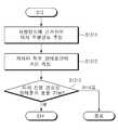
도 4는 본 발명의 일 실시예에 따른 주행모드에 따른 주행 가능 여부 확인 과정을 도시한 흐름도.
도 5는 본 발명의 다른 실시예에 따른 주행모드에 따른 주행 가능 여부 확인 과정을 도시한 흐름도.1 is a block diagram showing a configuration of a driver assistance device according to an embodiment of the present invention;
2 is a flowchart illustrating an operation method of a driver assistance device according to an embodiment of the present invention.
FIGS. 3A and 3B are schematic diagrams of a sensor-by-context detection area according to the present invention; FIG.
FIG. 4 is a flowchart illustrating a process for confirming whether or not a vehicle can travel according to a travel mode according to an exemplary embodiment of the present invention. FIG.
FIG. 5 is a flowchart illustrating a travel-availability check process according to a travel mode according to another embodiment of the present invention; FIG.
이하, 첨부한 도면들을 참조하여 본 발명의 실시예들을 상세하게 설명한다.Hereinafter, embodiments of the present invention will be described in detail with reference to the accompanying drawings.
본 명세서에서 어떤 부분이 어떤 구성요소를 "포함"한다고 할 때, 이는 특별히 반대되는 기재가 없는 한 다른 구성요소를 제외하는 것이 아니라 다른 구성요소를 더 포함할 수 있는 것을 의미한다.Whenever a component is referred to as "comprising ", it is to be understood that the component may include other components as well, without departing from the scope of the present invention.
또한, 명세서에 기재된 "…부", "…기", "모듈" 등의 용어는 적어도 하나의 기능이나 동작을 처리하는 단위를 의미하며, 이는 하드웨어나 소프트웨어 또는 하드웨어 및 소프트웨어의 결합으로 구현될 수 있다. 또한, "일", "하나" 및 "그" 등의 관사는 본 발명을 기술하는 문맥에 있어서 본 명세서에 달리 지시되거나 문맥에 의해 분명하게 반박되지 않는 한, 단수 및 복수 모두를 포함하는 의미로 사용될 수 있다.
Also, the terms " part, ""module," and " module ", etc. in the specification mean a unit for processing at least one function or operation and may be implemented by hardware or software or a combination of hardware and software have. It is also to be understood that the articles "a", "an", "an" and "the" Can be used.
도 1은 본 발명의 일 실시예에 따른 운전자 보조장치의 구성을 도시한 블록도이다.1 is a block diagram illustrating the configuration of a driver assistance device according to an embodiment of the present invention.
도 1을 참조하면, 본 발명에 따른 운전자 보조장치는 센서모듈(10), 조향제어장치(20), 제동제어장치(30), 메모리(40), 제어부(50)를 포함한다.Referring to FIG. 1, a driver assistance device according to the present invention includes a
센서모듈(10)은 차량 내 장착된 서로 다른 둘 이상의 센서들로 구성된다. 이러한 센서모듈(10)은 카메라(11), 레이더(radar)(12), 초음파 센서(13), 차량 센서(14)를 포함한다. 센서모듈(10)은 상기한 센서들 외 라이더(LiDAR)와 같은 센서를 더 포함할 수도 있다.The
카메라(11)는 차량의 전방, 후방, 측방 중 어느 하나의 위치에 설치되어 차량의 주변영상을 촬영한다. 이러한 카메라(11)는 전방향카메라, CCD(charge-coupled device) 카메라, CMOS(complementary metal-oxide semiconductor) 카메라로 구현될 수 있다.The
카메라(11)는 이미지 센서를 통해 획득한 영상에 대해 노이즈(noise) 제거, 컬러재현, 화질 및 채도 조절, 파일 압축 등의 이미지 처리를 수행하는 이미지 처리기를 포함할 수 있다.The
레이더(12)는 차량과 전방 객체(예: 차량, 보행자 등) 간의 거리를 측정한다.The
초음파 센서(13)는 차량과 근접한 거리에 위치하는 객체와의 거리를 측정한다.The ultrasonic sensor 13 measures the distance to an object located at a distance close to the vehicle.
차량 센서(13)는 차량 내에 장착된 센서로, 조향각 센서, 요레이트 센서, 차속 센서 등을 포함한다. 차량 센서(13)는 차량 내 장착된 센서를 통해 차량정보를 감지한다.The vehicle sensor 13 is a sensor mounted in the vehicle, and includes a steering angle sensor, a yaw rate sensor, a vehicle speed sensor, and the like. The vehicle sensor 13 senses the vehicle information through a sensor mounted in the vehicle.
조향제어장치(20)는 조향각을 조절하여 차륜을 조향한다.The
제동제어장치(30)는 제동토크를 조절하여 차륜의 제동력을 제어한다.The braking control device (30) controls the braking force of the wheel by adjusting the braking torque.
메모리(40)는 제어부(50)의 동작을 위한 프로그램을 저장할 수 있으며 센서모듈(10)을 통해 측정한 데이터를 임시 저장할 수 있다. 또한, 메모리(40)는 운전자 보조 기능 작동을 위한 프로그램 및 차량의 폭과 같은 제반 정보가 저장된다.The
제어부(50)는 센서모듈(10)의 카메라(11) 및 레이더(12), 차량 센서(14)을 통해 측정한 측정데이터에 근거하여 주행모드를 결정한다. 다시 말해서, 제어부(50)는 차량 속도, 보행자 밀집도(보행자 수/거리), 주변환경정보(외벽, 가드레일, 차량 등) 및 차량속도를 고려하여 주행모드를 결정한다. 여기서, 주행모드는 접촉사고 방지모드 및 보행자 보호모드로 구분된다.The
본 실시예에서는 센서들에 의해 측정된 데이터에 근거하여 주행모드를 결정하는 것을 설명하고 있으나, 이에 한정되지 않고 별도로 구비된 버튼을 조작하여 주행모드를 입력하도록 구현할 수도 있다. 예컨대, 운전자 보조장치는 접촉사고 방지모드 버튼 및 보행자 보호모드 버튼을 구비할 수 있다. 이와 같이, 운전이 능숙하거나 미숙한 운전자가 버튼 조작을 통해 주행모드를 선택할 수 있도록 하므로, 접촉사고 방지모드 또는 보행자 보호모드로 빈번하게 작동하는 것을 방지하면 동시에 센서 신뢰도를 향상시킬 수 있다.In the present embodiment, the traveling mode is determined based on the data measured by the sensors. However, the present invention is not limited to this, and the traveling mode may be input by operating the separately provided button. For example, the driver assistance device may include a contact accident prevention mode button and a pedestrian protection mode button. In this way, a driver who is skilled or unskilled can select the driving mode through the button operation, so that it is possible to prevent the frequent operation in the contact accident prevention mode or the pedestrian protection mode, and at the same time, the sensor reliability can be improved.
제어부(50)는 주행모드가 결정되면 결정한 주행모드에 따라 센서모듈(10)의 센서들을 조합하여 주행 가능 여부를 확인한다. 제어부(50)는 카메라(11), 레이더(12) 및 초음파 센서(13)를 통해 진행방향으로 주행 가능여부를 결정한다.When the driving mode is determined, the
제어부(50)는 주행모드가 접촉사고 방지모드이면 차량 센서(14)를 통해 획득한 차량 정보(상태정보)에 근거하여 차량의 주행경로를 추정(예측)한다. 여기서, 차량 정보는 조향각 및 요레이트(yaw rate)를 포함한다. 그리고, 제어부(50)는 카메라(11), 레이더(12) 및 초음파 센서(13)를 통해 차량과 전방 좌우 장애물(객체) 간의 거리를 측정하여 차량이 통과할 수 있는지 여부를 확인한다.The
한편, 제어부(50)는 주행모드가 보행자 보호모드이면 카메라(11) 및 초음파 센서(13)로 획득한 정보에 근거하여 차량 진행경로 상에 있는 보행자의 위치를 측정하고 차량과 보행자 간의 충돌 가능성이 있는지를 확인한다.On the other hand, when the driving mode is the pedestrian protection mode, the
제어부(50)는 주행 가능 여부에 따라 조향 및 제동 중 하나 이상을 제어할 수 있는 운전자 보조 정보(조향각 및 제동토크 등)를 생성하여 조향제어장치(20) 및 제동제어장치(30)로 전송한다. 조향제어장치(20) 및 제동제어장치(30)는 운전자 보조 정보에 따라 차량의 조향 및 제동을 제어한다. 즉, 제어부(50)는 근접거리 장애물 및 보행자와의 충돌을 회피하여 주행하도록 제어한다.The
도 2는 본 발명의 일 실시예에 따른 운전자 보조장치의 작동방법을 도시한 흐름도이고, 도 3a 및 도 3b는 본 발명과 관련된 상황별 센서 검지 영역을 도식화한 도면이다.FIG. 2 is a flowchart illustrating an operation method of the driver assistance device according to an exemplary embodiment of the present invention, and FIGS. 3A and 3B are diagrams illustrating a sensor detection area according to the present invention.
제어부(50)는 센서모듈(10)을 통해 차량의 주행환경을 인식한다(S11). 제어부(50)는 차량 센서(14)를 통해 차량 속도를 확인하고, 카메라(11) 및 레이더(12)를 통해 보행자 밀집도 및 주변환경(외벽, 가드레일, 차량 등)을 인식한다.The
제어부(50)는 차량 센서(14)를 통해 측정한 차량 속도가 기준 속도(예: 30km/h)이하로 일정 시간(예: 1분) 동안 주행을 하면 저속구간 진입으로 인식한다. 저속구간은 주차장 진출입로, 협로, 골목길 등과 같은 접촉사고 가능성이 높은 지역을 말한다. 그리고, 제어부(50)는 차량 주행 경로 상에 횡단보도 및 시장, 인도/차도 공용도로 등과 같이 보행자가 밀집된 구간이 있는지를 확인한다.The
제어부(50)는 인식한 주행 환경에 따라 주행모드를 결정한다(S12). 제어부(50)는 저속구간으로 진입 중이면 주행모드를 접촉사고 방지모드로 결정한다. 한편, 제어부(50)는 저속구간에서 인구 과밀 지역으로 진행 중이면 보행자 보호 모드로 결정한다.The
제어부(50)는 차량 속도, 보행자 밀집도, 주변환경정보를 고려하여 접촉사고 방지모드 또는 보행자 보호모드로 결정한다.The
제어부(50)는 결정된 주행모드에 따라 센서모듈(10) 내 하나 이상의 센서들을 조합하여 주행 가능 여부를 확인한다(S13). 제어부(50)는 주행모드가 접촉사고 방지모드이면 카메라(11), 레이더(12), 초음파 센서(13)를 통해 차량과 전방 장애물 간의 거리를 측정하고, 차량 센서(14)를 통해 조향각 및 요레이트와 같은 차량정보를 측정한다.The
한편, 제어부(50)는 주행모드가 보행자 보호모드이면 카메라(11) 및 초음파 센서(13)를 이용해 주행경로 상 근접거리에 있는 보행자 위치를 확인하고 그 보행자와의 충돌 가능성을 판단한다.On the other hand, if the driving mode is the pedestrian protection mode, the
제어부(50)는 주행가능여부에 따라 차량의 조향 및 제동을 제어한다(S14). 제어부(50)는 조향제어장치(20) 및 제동제어장치(30)를 제어하여 차량의 조향 및/또는 제동을 제어하여 회피 주행을 할 수 있도록 한다.The
예를 들어, 도 3a에 도시된 바와 같이 나선형 주차장 진출입로 또는 협로 주행 시 제어부(50)는 카메라(11) 및 초음파 센서(13)를 통해 근접거리 전방 좌우 장애물을 초음파 센서(13)를 통해 검지(센싱)한다. 이와 같이, 본 발명은 초음파 센서(13)를 통해 근접거리 장애물을 감지하고 그에 따라 좌우 조향 및 제동을 제어하므로 해당 장애물과의 충돌을 회피할 수 있게 한다.For example, as shown in FIG. 3A, when the vehicle enters or exits the spiral parking lot, the
또한, 도 3b에 도시된 바와 같이, 차량의 전방에 보행자들이 밀집되어 있는 경우 제어부(50)는 카메라(11) 및 초음파 센서(13)를 이용하여 차량 진행경로 상 근접하게 있는 보행자를 감지하고, 그 감지한 보행자와 충돌 가능성이 있는지를 확인한다. 그리고, 제어부(50)는 감지한 보행자와의 충돌 가능성이 있으면 좌우 조향 및 제동을 제어하여 충돌을 회피하게 한다.3B, when the pedestrians are densely packed in front of the vehicle, the
도 4는 본 발명의 일 실시예에 따른 주행모드에 따른 주행 가능 여부 확인 과정을 도시한 흐름도이다.FIG. 4 is a flowchart illustrating a process of confirming whether or not a vehicle can travel in accordance with a travel mode according to an embodiment of the present invention.
제어부(50)는 차량정보에 근거하여 자차 주행경로를 추정한다(S1311). 제어부(50)는 차량 센서(14)를 통해 획득한 차량의 조향각 및 요레이트를 이용하여 자차의 주행경로를 추정한다.The
제어부(50)는 자차와 전방 좌우 장애물 간의 거리를 측정한다(S1312). 이때, 제어부(50)는 초음파 센서(13)를 추가로 구동시켜 자차로부터 근접한 거리에 위치하는 전방 좌우 장애물과의 거리를 측정한다.The
제어부(50)는 자차 주행경로 및 장애물과의 거리를 기반으로 주행경로 상에서 장애물과의 충돌 가능성이 있는지를 확인한다(S1313). 예를 들어, 주행 도로의 좌측 및 우측에 각각 차량이 위치하는 경우, 제어부(50)는 두 차량과의 충돌 가능성이 있는지를 확인한다. 그리고, 제어부(50)는 그 확인결과 충돌 가능성이 있으면 운전자 보조 정보를 생성하여 조향제어장치(20) 및 제동제어장치(30)를 제어한다. 따라서, 자차는 조향 및 제동 제어를 통해 진행방향으로 근접하게 좌측 및 우측에 각각 위치한 차량과 충돌하지 않고 통과할 수 있다.The
도 5는 본 발명의 다른 실시예에 따른 주행모드에 따른 주행 가능 여부 확인 과정을 도시한 흐름도이다.FIG. 5 is a flowchart illustrating a process for confirming whether or not a vehicle can travel in accordance with a travel mode according to another embodiment of the present invention.
제어부(50)는 차량 진행경로 상에 존재하는 보행자의 위치를 측정한다(S1321).The
제어부(50)는 자차가 보행자와 충돌할 가능성이 있는지를 확인한다(S1322). 이때, 제어부(50)는 카메라(11) 및 초음파 센서(13)를 이용해 차량 진행경로 상 근접한 거리에 위치한 보행자 위치를 측정한다. 그리고, 제어부(50)는 자차와 해당 보행자의 충돌 가능성이 있는지를 확인한다.The
이상에서 설명된 실시예들은 본 발명의 구성요소들과 특징들이 소정 형태로 결합된 것들이다. 각 구성요소 또는 특징은 별도의 명시적 언급이 없는 한 선택적인 것으로 고려되어야 한다. 각 구성요소 또는 특징은 다른 구성요소나 특징과 결합되지 않은 형태로 실시될 수 있다. 또한, 일부 구성요소들 및/또는 특징들을 결합하여 본 발명의 실시예를 구성하는 것도 가능하다. 본 발명의 실시예들에서 설명되는 동작들의 순서는 변경될 수 있다. 어느 실시예의 일부 구성이나 특징은 다른 실시예에 포함될 수 있고, 또는 다른 실시예의 대응하는 구성 또는 특징과 교체될 수 있다. 특허청구범위에서 명시적인 인용 관계가 있지 않은 청구항들을 결합하여 실시예를 구성하거나 출원 후의 보정에 의해 새로운 청구항으로 포함시킬 수 있음은 자명하다.The embodiments described above are those in which the elements and features of the present invention are combined in a predetermined form. Each component or feature shall be considered optional unless otherwise expressly stated. Each component or feature may be implemented in a form that is not combined with other components or features. It is also possible to construct embodiments of the present invention by combining some of the elements and / or features. The order of the operations described in the embodiments of the present invention may be changed. Some configurations or features of certain embodiments may be included in other embodiments, or may be replaced with corresponding configurations or features of other embodiments. It is clear that the claims that are not expressly cited in the claims may be combined to form an embodiment or be included in a new claim by an amendment after the application.
본 발명에 따른 실시예는 다양한 수단, 예를 들어, 하드웨어, 펌웨어(firmware), 소프트웨어 또는 그것들의 결합 등에 의해 구현될 수 있다. 하드웨어에 의한 구현의 경우, 본 발명의 일 실시예는 하나 또는 그 이상의 ASICs(application specific integrated circuits), DSPs(digital signal processors), DSPDs(digital signal processing devices), PLDs(programmable logic devices), FPGAs(field programmable gate arrays), 프로세서, 콘트롤러, 마이크로 콘트롤러, 마이크로 프로세서 등에 의해 구현될 수 있다.Embodiments in accordance with the present invention may be implemented by various means, for example, hardware, firmware, software, or a combination thereof. In the case of hardware implementation, an embodiment of the present invention may include one or more application specific integrated circuits (ASICs), digital signal processors (DSPs), digital signal processing devices (DSPDs), programmable logic devices (PLDs) field programmable gate arrays, processors, controllers, microcontrollers, microprocessors, and the like.
펌웨어나 소프트웨어에 의한 구현의 경우, 본 발명의 일 실시예는 이상에서 설명된 기능 또는 동작들을 수행하는 모듈, 절차, 함수 등의 형태로 구현될 수 있다. 소프트웨어 코드는 메모리 유닛에 저장되어 프로세서에 의해 구동될 수 있다. 메모리 유닛은 프로세서 내부 또는 외부에 위치하여, 이미 공지된 다양한 수단에 의해 프로세서와 데이터를 주고 받을 수 있다.In the case of an implementation by firmware or software, an embodiment of the present invention may be implemented in the form of a module, a procedure, a function, or the like which performs the functions or operations described above. The software code can be stored in a memory unit and driven by the processor. The memory unit is located inside or outside the processor, and can exchange data with the processor by various known means.
본 발명은 본 발명의 특징을 벗어나지 않는 범위에서 다른 특정한 형태로 구체화될 수 있음은 당업자에게 자명하다. 따라서, 상술한 상세한 설명은 모든 면에서 제한적으로 해석되어서는 아니되고 예시적인 것으로 고려되어야 한다. 본 발명의 범위는 첨부된 청구항의 합리적 해석에 의해 결정되어야 하고, 본 발명의 등가적 범위 내에서의 모든 변경은 본 발명의 범위에 포함된다.It will be apparent to those skilled in the art that the present invention may be embodied in other specific forms without departing from the spirit of the invention. Accordingly, the foregoing detailed description is to be considered in all respects illustrative and not restrictive. The scope of the present invention should be determined by rational interpretation of the appended claims, and all changes within the scope of equivalents of the present invention are included in the scope of the present invention.
10: 센서모듈
11: 카메라
12: 레이더
13: 초음파 센서
14: 차량 센서
20: 조향제어장치
30: 제동제어장치
40: 메모리
50: 제어부10: Sensor module
11: Camera
12: Radar
13: Ultrasonic sensor
14: Vehicle sensor
20: Steering control device
30: Braking control device
40: Memory
50:
Claims (14)
Translated fromKorean상기 주행 환경에 따라 주행모드를 결정하는 단계와,
상기 주행모드에 따라 둘 이상의 센서를 조합하여 주행가능여부를 확인하는 단계와,
상기 주행가능여부에 따라 조향 및 제동을 제어하는 단계를 포함하며,
상기 주행 환경 인식 단계는, 차량속도에 근거하여 차량이 기준 속도 이하의 저속구간에 진입했는지를 인식하는 것을 특징으로 하는 운전자 보조장치의 작동 방법.Recognizing a driving environment of the vehicle,
Determining a driving mode according to the driving environment;
Checking whether or not the vehicle can be traveled by combining two or more sensors according to the travel mode,
And controlling steering and braking according to whether or not the vehicle is capable of traveling,
Wherein the driving environment recognition step recognizes whether the vehicle has entered a low speed section below the reference speed based on the vehicle speed.
상기 주행모드 결정 단계는,
차량 속도, 보행자 밀집도, 주변환경정보를 고려하여 접촉사고 방지모드 또는 보행자 보호모드로 결정하는 것을 특징으로 하는 운전자 보조장치의 작동 방법.The method according to claim 1,
The driving mode determination step may include:
A pedestrian protection mode, and a pedestrian protection mode in consideration of vehicle speed, pedestrian density, and surrounding environment information.
상기 주행가능여부 확인단계는,
차량정보에 근거하여 자차 주행경로를 추정하는 단계와,
상기 자차와 근접거리 장애물 간의 거리를 측정하는 단계와,
상기 자차 주행경로 및 거리에 근거하여 상기 자차 주행경로 상에서 상기 자차와 장애물의 충돌 가능여부를 확인하는 단계를 포함하는 것을 특징으로 하는 운전자 보조장치의 작동 방법.The method according to claim 1,
The step of confirming whether or not the vehicle can travel,
Estimating a self-drive travel route based on the vehicle information,
Measuring a distance between the vehicle and the proximity obstacle;
And checking whether a collision between the vehicle and the obstacle is possible on the vehicle traveling route based on the vehicle traveling route and the distance.
상기 자차 주행경로 추정 단계는,
차량 센서를 통해 획득한 조향각 및 요레이트를 이용하여 자차의 주행경로를 추정하는 것을 특징으로 하는 운전자 보조장치의 작동 방법.The method of claim 3,
Wherein the self-traveling path estimating step comprises:
And estimating a driving route of the vehicle using the steering angle and the yaw rate acquired through the vehicle sensor.
상기 거리 측정 단계는,
카메라 및 초음파 센서를 이용하여 상기 자차와 근접거리 장애물 간의 거리를 측정하는 것을 특징으로 하는 운전자 보조장치의 작동 방법.The method of claim 3,
The distance measuring step may include:
Wherein the distance between the vehicle and the proximity obstacle is measured using a camera and an ultrasonic sensor.
상기 주행가능여부 확인단계는,
차량 진행경로 상 보행자의 위치를 측정하는 단계와,
상기 보행자와 자차의 충돌 가능 여부를 확인하는 단계를 포함하는 것을 특징으로 하는 운전자 보조장치의 작동 방법.The method according to claim 1,
The step of confirming whether or not the vehicle can travel,
Measuring a position of a pedestrian on a vehicle traveling path,
And checking whether the pedestrian and the vehicle can collide with each other.
상기 보행자 위치 측정 단계는,
초음파 센서 및 카메라를 통해 보행자 위치를 측정하는 것을 특징으로 하는 운전자 보조장치의 작동 방법.The method according to claim 6,
The pedestrian position measuring step may include:
Wherein the position of the pedestrian is measured through an ultrasonic sensor and a camera.
상기 차량의 조향을 제어하는 조향제어장치와,
상기 차량의 제동을 제어하는 제동제어장치와,
상기 센서모듈을 통해 측정한 측정데이터에 근거하여 주행모드를 결정하고 그 결정한 주행모드에 따라 상기 센서들의 조합으로 주행 가능 여부를 확인하여 그 확인결과에 따라 상기 차량의 조향 및 제동을 제어하는 제어부를 포함하며,
상기 제어부는 차량속도에 근거하여 차량이 기준 속도 이하의 저속구간에 진입했는지를 인식하는 것을 특징으로 하는 운전자 보조장치.A sensor module including two or more different sensors for sensing a vehicle periphery image, a distance between a vehicle and an obstacle, and vehicle state information,
A steering control device for controlling steering of the vehicle;
A braking control device for controlling the braking of the vehicle;
Determining a driving mode based on measurement data measured through the sensor module, checking whether the vehicle can be traveled in combination with the sensors according to the determined traveling mode, and controlling the steering and braking of the vehicle according to the determined result ≪ / RTI &
Wherein the control unit recognizes whether the vehicle has entered a low speed section lower than the reference speed based on the vehicle speed.
상기 센서모듈은,
카메라, 레이더, 초음파 센서, 차량 센서를 포함하는 것을 특징으로 하는 운전자 보조장치.9. The method of claim 8,
The sensor module includes:
A camera, a radar, an ultrasonic sensor, and a vehicle sensor.
상기 제어부는,
상기 카메라, 상기 레이더, 상기 차량 센서를 통해 보행자 밀집도, 주변환경정보, 차량속도를 고려하여 접촉사고 방지모드 또는 보행자 보호모드로 주행모드를 결정하는 것을 특징으로 하는 운전자 보조장치.10. The method of claim 9,
Wherein,
Wherein the driving mode is determined in a contact accident prevention mode or a pedestrian protection mode in consideration of pedestrian density, surrounding environment information, and vehicle speed through the camera, the radar, and the vehicle sensor.
상기 제어부는,
상기 주행모드가 접촉사고 방지모드인 경우, 상기 차량센서를 통해 획득한 차량정보에 근거하여 자차 주행경로를 추정하는 것을 특징으로 하는 운전자 보조장치.11. The method of claim 10,
Wherein,
And estimates a self-running travel route based on the vehicle information obtained through the vehicle sensor when the traveling mode is the contact-accident preventing mode.
상기 제어부는,
상기 카메라 및 상기 초음파 센서를 통해 자차와 근접거리 장애물 간의 거리를 측정하여 상기 자차 주행경로 상에서 상기 자차와 장애물의 충돌 가능여부를 확인하는 것을 특징으로 하는 운전자 보조장치.12. The method of claim 11,
Wherein,
Wherein the distance between the vehicle and the proximity obstacle is measured through the camera and the ultrasonic sensor to confirm whether or not the vehicle can collide with the obstacle on the vehicle traveling route.
상기 제어부는,
상기 주행모드가 보행자 보호모드인 경우, 상기 카메라 및 상기 초음파 센서를 통해 차량 진행경로 상 보행자의 위치를 측정하고 상기 보행자와 자차의 충돌 가능 여부를 확인하는 것을 특징으로 하는 운전자 보조장치.11. The method of claim 10,
Wherein,
Wherein when the driving mode is the pedestrian protection mode, the position of the pedestrian on the vehicle progress path is measured through the camera and the ultrasonic sensor, and whether the pedestrian and the vehicle can collide with each other is confirmed.
상기 주행모드를 결정하기 위한 버튼을 더 포함하는 것을 특징으로 하는 운전자 보조장치.9. The method of claim 8,
Further comprising a button for determining the driving mode.
Priority Applications (3)
| Application Number | Priority Date | Filing Date | Title |
|---|---|---|---|
| KR1020140146195AKR101628503B1 (en) | 2014-10-27 | 2014-10-27 | Driver assistance apparatus and method for operating thereof |
| US14/716,474US9731717B2 (en) | 2014-10-27 | 2015-05-19 | Driver assistance apparatus and method for operating the same |
| US15/391,355US10407060B2 (en) | 2014-10-27 | 2016-12-27 | Driver assistance apparatus and method for operating the same |
Applications Claiming Priority (1)
| Application Number | Priority Date | Filing Date | Title |
|---|---|---|---|
| KR1020140146195AKR101628503B1 (en) | 2014-10-27 | 2014-10-27 | Driver assistance apparatus and method for operating thereof |
Publications (2)
| Publication Number | Publication Date |
|---|---|
| KR20160049291A KR20160049291A (en) | 2016-05-09 |
| KR101628503B1true KR101628503B1 (en) | 2016-06-08 |
Family
ID=55791354
Family Applications (1)
| Application Number | Title | Priority Date | Filing Date |
|---|---|---|---|
| KR1020140146195AActiveKR101628503B1 (en) | 2014-10-27 | 2014-10-27 | Driver assistance apparatus and method for operating thereof |
Country Status (2)
| Country | Link |
|---|---|
| US (2) | US9731717B2 (en) |
| KR (1) | KR101628503B1 (en) |
Cited By (3)
| Publication number | Priority date | Publication date | Assignee | Title |
|---|---|---|---|---|
| US10668924B2 (en) | 2016-11-29 | 2020-06-02 | Samsung Electronics Co., Ltd. | Method and apparatus to control velocity of vehicle |
| KR20210069111A (en)* | 2018-09-28 | 2021-06-10 | 바이두닷컴 타임즈 테크놀로지(베이징) 컴퍼니 리미티드 | A pedestrian interaction system for low speed scenes for autonomous vehicles |
| US12072432B2 (en) | 2019-06-21 | 2024-08-27 | Huawei Technologies Co., Ltd. | Sensor control method and apparatus, and sensor |
Families Citing this family (62)
| Publication number | Priority date | Publication date | Assignee | Title |
|---|---|---|---|---|
| JP6174516B2 (en)* | 2014-04-24 | 2017-08-02 | 本田技研工業株式会社 | Collision avoidance support device, collision avoidance support method, and program |
| KR101628503B1 (en)* | 2014-10-27 | 2016-06-08 | 현대자동차주식회사 | Driver assistance apparatus and method for operating thereof |
| US10167015B2 (en)* | 2015-05-11 | 2019-01-01 | GM Global Technology Operations LLC | System for retrofitting vehicle automation |
| JP6384446B2 (en)* | 2015-10-14 | 2018-09-05 | 株式会社デンソー | Vehicle control apparatus and vehicle control method |
| US10606257B2 (en) | 2015-11-10 | 2020-03-31 | Hyundai Motor Company | Automatic parking system and automatic parking method |
| KR101892026B1 (en)* | 2015-11-10 | 2018-08-27 | 현대자동차주식회사 | Remote control car parking method and apparatus |
| US10919574B2 (en) | 2015-11-10 | 2021-02-16 | Hyundai Motor Company | Automatic parking system and automatic parking method |
| US10906530B2 (en) | 2015-11-10 | 2021-02-02 | Hyundai Motor Company | Automatic parking system and automatic parking method |
| JP6344402B2 (en)* | 2016-01-20 | 2018-06-20 | トヨタ自動車株式会社 | Vehicle driving support device |
| US9796390B2 (en)* | 2016-02-29 | 2017-10-24 | Faraday&Future Inc. | Vehicle sensing grid having dynamic sensing cell size |
| KR102513745B1 (en)* | 2016-04-15 | 2023-03-24 | 주식회사 에이치엘클레무브 | Driving assistance device |
| US10574305B2 (en)* | 2016-05-11 | 2020-02-25 | Magna Electronics Inc. | Vehicle secured communication system |
| CN106184202B (en)* | 2016-07-26 | 2019-05-14 | 浙江吉利控股集团有限公司 | A kind of control method of the automatic emergency steering system for vehicle |
| DE102016009760A1 (en)* | 2016-08-11 | 2018-02-15 | Trw Automotive Gmbh | Control system and control method for guiding a motor vehicle along a path |
| US11305766B2 (en)* | 2016-09-26 | 2022-04-19 | Iprd Group, Llc | Combining driver alertness with advanced driver assistance systems (ADAS) |
| JP6656129B2 (en)* | 2016-09-28 | 2020-03-04 | 日立オートモティブシステムズ株式会社 | Image processing device, imaging device |
| KR101844515B1 (en) | 2016-10-26 | 2018-05-14 | 삼성전자주식회사 | Portable medical apparatus, and method for controlling portable medical apparatus |
| CN106553647B (en)* | 2016-12-05 | 2020-02-18 | 上海振华重工(集团)股份有限公司 | Auxiliary driving system and method for flat car |
| US11733699B2 (en)* | 2017-06-16 | 2023-08-22 | FLIR Belgium BVBA | Ultrasonic perimeter ranging sensor systems and methods |
| JP2019051830A (en)* | 2017-09-15 | 2019-04-04 | ダイハツ工業株式会社 | Vehicle control device |
| CN109552308B (en)* | 2017-09-27 | 2022-03-11 | 奥迪股份公司 | Driving assistance apparatus and method for vehicle |
| KR102334158B1 (en)* | 2017-10-30 | 2021-12-02 | 현대모비스 주식회사 | Autonomous emergency braking apparatus and control method thereof |
| CN109747643B (en)* | 2017-11-07 | 2022-08-12 | 宇通客车股份有限公司 | Information fusion method of intelligent vehicle sensing system |
| KR102428660B1 (en)* | 2017-11-08 | 2022-08-03 | 현대자동차주식회사 | Vehicle and control method for the same |
| KR102397099B1 (en)* | 2017-11-15 | 2022-05-12 | 주식회사 만도 | Apparatus and method for controlling steering |
| CN108072875A (en)* | 2017-11-23 | 2018-05-25 | 李党 | Vehicle collision avoidance system |
| CN108189839A (en)* | 2017-12-15 | 2018-06-22 | 浙江海洋大学 | Continue rainfall road conditions auxiliary crane device and its application method |
| CN108407784B (en)* | 2018-01-23 | 2021-12-07 | 内蒙古青杉汽车有限公司 | Anti-collision control method and device based on fuzzy control theory |
| EP3575171B8 (en) | 2018-05-28 | 2025-02-19 | Qualcomm Auto Ltd. | Vehicle collision avoidance method and system |
| DE102018208831A1 (en)* | 2018-06-05 | 2019-12-05 | Robert Bosch Gmbh | Detection of an impact event |
| CN110654378B (en)* | 2018-06-29 | 2021-11-12 | 比亚迪股份有限公司 | Vehicle control method, device and system and vehicle |
| KR102589934B1 (en)* | 2018-09-13 | 2023-10-17 | 현대모비스 주식회사 | Apparatus and method for adjusting a warning condition |
| KR102570056B1 (en)* | 2018-12-17 | 2023-08-23 | 현대자동차주식회사 | Vehicle and control method of the same |
| CN110614995B (en)* | 2018-12-29 | 2021-01-22 | 长城汽车股份有限公司 | Lane selection method and system during automatic driving of vehicle and vehicle |
| DE102019218504A1 (en)* | 2019-01-30 | 2020-07-30 | Mando Corporation | DRIVER ASSISTANCE SYSTEM AND TAX METHOD THEREFOR |
| KR102695891B1 (en)* | 2019-02-01 | 2024-08-16 | 주식회사 에이치엘클레무브 | driver assistance apparatus |
| CN110077372A (en)* | 2019-04-29 | 2019-08-02 | 北京海纳川汽车部件股份有限公司 | The brake control method and vehicle of vehicle |
| KR102734270B1 (en)* | 2019-06-04 | 2024-11-26 | 주식회사 에이치엘클레무브 | Apparatus and method for driver assistance |
| CN112130551A (en)* | 2019-06-25 | 2020-12-25 | 北京百度网讯科技有限公司 | Travel path and speed decision planning method and device for unmanned vehicle |
| CN110161510B (en)* | 2019-06-27 | 2021-12-10 | 北京智行者科技有限公司 | Obstacle positioning method and device based on ultrasonic radar |
| CN110316185A (en)* | 2019-07-01 | 2019-10-11 | 百度在线网络技术(北京)有限公司 | Control method, device, equipment and the readable storage medium storing program for executing of car speed |
| KR102713947B1 (en)* | 2019-08-08 | 2024-10-04 | 엘지전자 주식회사 | Apparatus and method for controlling vehicle |
| CN110488319B (en)* | 2019-08-22 | 2023-04-07 | 重庆长安汽车股份有限公司 | Ultrasonic wave and camera fusion-based collision distance calculation method and system |
| KR20210026248A (en)* | 2019-08-29 | 2021-03-10 | 현대자동차주식회사 | Apparatus for notifying accident of a vehicle, system having the same and method thereof |
| CN110588645B (en)* | 2019-09-02 | 2020-12-29 | 武汉格罗夫氢能汽车有限公司 | Automatic emergency lane changing method and control system for avoiding collision of hydrogen energy automobile |
| CN110884487A (en)* | 2019-12-16 | 2020-03-17 | 清友(苏州)汽车技术有限公司 | Artificial intelligence device for vehicle to identify obstacle |
| KR20210130302A (en)* | 2020-04-21 | 2021-11-01 | 주식회사 만도모빌리티솔루션즈 | Driver assistance system and the conrol method of the same |
| CN111497835B (en)* | 2020-04-24 | 2022-03-08 | 北京智行者科技有限公司 | Vehicle parallel driving and automatic anti-collision system |
| CN111506084B (en)* | 2020-05-19 | 2021-09-28 | 安徽江淮汽车集团股份有限公司 | Obstacle avoidance method, apparatus, device and storage medium for unmanned vehicle |
| CN111746533A (en)* | 2020-06-30 | 2020-10-09 | 三一专用汽车有限责任公司 | Vehicle and vehicle control method |
| JP7564706B2 (en)* | 2020-12-24 | 2024-10-09 | 株式会社Subaru | Vehicle control device |
| CN112687173B (en)* | 2020-12-25 | 2022-06-21 | 安徽机电职业技术学院 | Automobile collision demonstration platform based on active and passive safety collaborative optimization |
| CN112622893A (en)* | 2020-12-25 | 2021-04-09 | 北京理工大学前沿技术研究院 | Multi-sensor fusion target vehicle automatic driving obstacle avoidance method and system |
| CN112622936B (en)* | 2020-12-30 | 2022-04-08 | 名商科技有限公司 | Intelligent steering method for electric automobile |
| CN112389455B (en)* | 2021-01-20 | 2021-04-06 | 国汽智控(北京)科技有限公司 | Method and system for protecting safe operation of automatic driving vehicle |
| JP7296553B2 (en)* | 2021-03-24 | 2023-06-23 | パナソニックIpマネジメント株式会社 | Object detection device |
| CN113238236A (en)* | 2021-04-07 | 2021-08-10 | 石爪兽(徐州)软件科技有限公司 | Method and device for monitoring, displaying and alarming reversing radar for electric vehicle |
| CN113335312B (en)* | 2021-08-06 | 2021-10-19 | 新石器慧通(北京)科技有限公司 | Obstacle-detouring driving method and device, electronic equipment and medium |
| KR20230073804A (en)* | 2021-11-19 | 2023-05-26 | 현대엠시스템즈 주식회사 | Apparatus for controlling driving of unmanned forklift using stereo camera and ultrasonic sensor and method thereof |
| KR20240114971A (en)* | 2023-01-18 | 2024-07-25 | 현대자동차주식회사 | Vehicle and method for controlling thereof |
| CN116853236B (en)* | 2023-07-12 | 2025-07-01 | 东风汽车集团股份有限公司 | A large vehicle right turn blind spot recognition active avoidance control method and system |
| CN119239601B (en)* | 2024-10-23 | 2025-07-15 | 重庆赛力斯凤凰智创科技有限公司 | Vehicle turning control method and intelligent driving controller |
Citations (1)
| Publication number | Priority date | Publication date | Assignee | Title |
|---|---|---|---|---|
| JP2008062666A (en)* | 2006-09-04 | 2008-03-21 | Toyota Motor Corp | Vehicle alarm device |
Family Cites Families (73)
| Publication number | Priority date | Publication date | Assignee | Title |
|---|---|---|---|---|
| DE4407757A1 (en)* | 1993-03-08 | 1994-09-15 | Mazda Motor | Device for detecting obstacles for a vehicle |
| JP3319229B2 (en)* | 1995-07-03 | 2002-08-26 | トヨタ自動車株式会社 | Vehicle travel control device |
| JPH09106500A (en) | 1995-10-12 | 1997-04-22 | Fuji Heavy Ind Ltd | Driving supporting device for vehicle |
| JP3245363B2 (en)* | 1996-08-29 | 2002-01-15 | 富士重工業株式会社 | Vehicle collision prevention device |
| KR200171898Y1 (en) | 1996-12-31 | 2000-04-01 | 정몽규 | Irradiation quantity control device of head light for a car |
| JP3827804B2 (en) | 1997-04-09 | 2006-09-27 | 富士重工業株式会社 | Vehicle driving support device |
| JP3917241B2 (en) | 1997-06-25 | 2007-05-23 | 富士重工業株式会社 | Vehicle driving support device |
| DE19741631B4 (en)* | 1997-09-20 | 2013-08-14 | Volkswagen Ag | Method and device for avoiding and / or minimizing conflict situations in road traffic |
| US6642839B1 (en)* | 2000-02-16 | 2003-11-04 | Altra Technologies Incorporated | System and method of providing scalable sensor systems based on stand alone sensor modules |
| DE10036276A1 (en)* | 2000-07-26 | 2002-02-07 | Daimler Chrysler Ag | Automatic braking and steering system for a vehicle |
| JP3838005B2 (en)* | 2000-08-18 | 2006-10-25 | 日産自動車株式会社 | Vehicle collision prevention device |
| DE10118903A1 (en)* | 2001-04-18 | 2002-11-14 | Bosch Gmbh Robert | Multi-purpose driver assistance system for a motor vehicle |
| JP4509429B2 (en)* | 2001-06-25 | 2010-07-21 | 株式会社ホンダエレシス | Obstacle recognition method and recognition processing apparatus using a stereo camera |
| DE50206672D1 (en)* | 2001-07-11 | 2006-06-08 | Bosch Gmbh Robert | METHOD AND DEVICE FOR TRIGGERING AND PERFORMING A DELAY OF A VEHICLE |
| JP3642308B2 (en)* | 2001-10-04 | 2005-04-27 | 日産自動車株式会社 | Brake control device for vehicle |
| US6498972B1 (en)* | 2002-02-13 | 2002-12-24 | Ford Global Technologies, Inc. | Method for operating a pre-crash sensing system in a vehicle having a countermeasure system |
| US6950014B2 (en)* | 2002-02-13 | 2005-09-27 | Ford Global Technologies Llc | Method for operating a pre-crash sensing system in a vehicle having external airbags |
| US6771208B2 (en)* | 2002-04-24 | 2004-08-03 | Medius, Inc. | Multi-sensor system |
| JP3938013B2 (en) | 2002-11-12 | 2007-06-27 | 日産自動車株式会社 | Vehicle notification device |
| US7027920B2 (en)* | 2003-07-18 | 2006-04-11 | Visteon Global Technologies, Inc. | Low-speed collision avoidance system |
| JP4647201B2 (en)* | 2003-12-05 | 2011-03-09 | 富士重工業株式会社 | Vehicle travel control device |
| DE102004054720A1 (en)* | 2004-11-12 | 2006-05-18 | Daimlerchrysler Ag | Method for operating a vehicle with a collision avoidance system and apparatus for carrying out such a method |
| WO2006063827A1 (en)* | 2004-12-15 | 2006-06-22 | Magna Donnelly Electronics Naas Limited | An accessory module system for a vehicle window |
| DE102005003274A1 (en)* | 2005-01-25 | 2006-07-27 | Robert Bosch Gmbh | Collision occurrence preventing or reducing method for use in vehicle, involves identifying obstacle using field sensor, determining data of obstacle, and determining vehicle deceleration based on the data of obstacle and data of vehicle |
| DE102005009146A1 (en)* | 2005-03-01 | 2006-09-21 | Robert Bosch Gmbh | Driver assistance system with several assistance functions |
| JP2005247307A (en) | 2005-04-06 | 2005-09-15 | Equos Research Co Ltd | Vehicle safe driving support device |
| FR2887669A3 (en)* | 2005-06-27 | 2006-12-29 | Renault Sas | METHOD AND IMPROVED SHOCK PREDICTION SYSTEM BETWEEN A VEHICLE AND A PIETON |
| EP1944187B1 (en)* | 2005-08-04 | 2013-11-13 | Volvo Car Corporation | Automatic collision management system |
| JP2007062604A (en)* | 2005-08-31 | 2007-03-15 | Toyota Motor Corp | Automatic braking system for vehicles |
| US7375620B2 (en)* | 2005-12-08 | 2008-05-20 | Gm Global Technology Operations, Inc. | Speed-sensitive rear obstacle detection and avoidance system |
| KR20070060539A (en) | 2005-12-08 | 2007-06-13 | 기아자동차주식회사 | Front blind guard of car |
| JP5130638B2 (en)* | 2006-03-22 | 2013-01-30 | 日産自動車株式会社 | Avoidance operation calculation device, avoidance control device, vehicle including each device, avoidance operation calculation method, and avoidance control method |
| DE102006033145A1 (en)* | 2006-07-18 | 2008-01-24 | Robert Bosch Gmbh | Method and device for avoiding and / or reducing the consequences of collisions |
| US20080059069A1 (en)* | 2006-08-30 | 2008-03-06 | Trutna William R | System and method for detecting an object in the path of a vehicle |
| US20080065328A1 (en)* | 2006-09-08 | 2008-03-13 | Andreas Eidehall | Method and system for collision avoidance |
| EP2122599B1 (en)* | 2007-01-25 | 2019-11-13 | Magna Electronics Inc. | Radar sensing system for vehicle |
| JP2008242544A (en)* | 2007-03-26 | 2008-10-09 | Hitachi Ltd | Collision avoidance apparatus and method |
| US7831391B2 (en)* | 2007-06-12 | 2010-11-09 | Palo Alto Research Center Incorporated | Using segmented cones for fast, conservative assessment of collision risk |
| JP2009096273A (en)* | 2007-10-16 | 2009-05-07 | Hitachi Ltd | Collision avoidance control device |
| DE102008003205A1 (en)* | 2008-01-04 | 2009-07-09 | Wabco Gmbh | Device, method and computer program for collision avoidance or for reducing the collision severity as a result of a collision for vehicles, in particular commercial vehicles |
| JP5345350B2 (en)* | 2008-07-30 | 2013-11-20 | 富士重工業株式会社 | Vehicle driving support device |
| JP5210233B2 (en)* | 2009-04-14 | 2013-06-12 | 日立オートモティブシステムズ株式会社 | Vehicle external recognition device and vehicle system using the same |
| DE102010002105A1 (en)* | 2010-02-18 | 2011-08-18 | Robert Bosch GmbH, 70469 | Method for assisting a driver of a vehicle in a driving maneuver |
| DE102010029465A1 (en)* | 2010-05-28 | 2011-12-01 | Continental Teves Ag & Co. Ohg | Motor car communication module, has vehicle-to-vehicle/vehicle-to-infrastructure communication components for vehicle safety communications comprising wireless communication based on integration of data packets |
| KR20120036440A (en) | 2010-10-08 | 2012-04-18 | 주식회사 만도 | Apparatus for preventing collision of a car |
| US8527172B2 (en)* | 2010-10-20 | 2013-09-03 | GM Global Technology Operations LLC | Vehicle collision avoidance and warning system |
| DE102010061829A1 (en) | 2010-11-24 | 2012-05-24 | Continental Teves Ag & Co. Ohg | Method and distance control device for avoiding collisions of a motor vehicle in a driving situation with a small side clearance |
| JP5189157B2 (en)* | 2010-11-30 | 2013-04-24 | 株式会社豊田中央研究所 | Moving object target state determination device and program |
| DE102010053350A1 (en)* | 2010-12-03 | 2012-06-06 | Daimler Ag | Vehicle driving method involves performing automatic operation in braking and/or steering functions of vehicle and/or controlling and triggering occupant protection unit, in response to amount of collision probability of warning to driver |
| KR20120072131A (en)* | 2010-12-23 | 2012-07-03 | 한국전자통신연구원 | Context-aware method using data fusion of image sensor and range sensor, and apparatus thereof |
| JP5206804B2 (en)* | 2011-01-21 | 2013-06-12 | 株式会社デンソー | In-vehicle system |
| JP5656732B2 (en)* | 2011-05-02 | 2015-01-21 | 株式会社デンソー | Collision probability computation device and collision probability computation program |
| EP2728563A4 (en)* | 2011-06-13 | 2015-03-04 | Toyota Motor Co Ltd | DRIVER ASSISTING DEVICE AND DRIVER ASSISTING METHOD |
| KR20120140545A (en)* | 2011-06-21 | 2012-12-31 | 현대자동차주식회사 | A system for protecting a walker of vehicle |
| US9511751B2 (en)* | 2011-07-22 | 2016-12-06 | GM Global Technology Operations LLC | Object identification and active safety control for vehicles |
| EP2750118B1 (en)* | 2011-08-26 | 2020-01-01 | Toyota Jidosha Kabushiki Kaisha | Driving support apparatus and driving support method |
| WO2013046300A1 (en)* | 2011-09-26 | 2013-04-04 | トヨタ自動車株式会社 | Vehicle driving assistance system |
| JP2013093013A (en)* | 2011-10-06 | 2013-05-16 | Ricoh Co Ltd | Image processing device and vehicle |
| FR2987018B1 (en)* | 2012-02-16 | 2014-03-28 | Peugeot Citroen Automobiles Sa | AUTOMATIC BRAKE METHOD FOR MOTOR VEHICLE. |
| EP2679450B1 (en)* | 2012-06-27 | 2016-07-20 | Volvo Car Corporation | System for protection of a vulnerable road user and method for operating the system |
| DE102013103626A1 (en)* | 2012-12-20 | 2014-06-26 | Continental Teves Ag & Co. Ohg | Method for automatically braking and steering vehicle, involves detecting surrounding of vehicle environment by system, and determining order of automatic steering or braking operations based on relative speed of collision object |
| US9569968B2 (en)* | 2012-12-20 | 2017-02-14 | Continental Teves Ag & Co. Ohg | Method and device for the automated braking and steering of a vehicle |
| JP6022983B2 (en)* | 2013-03-29 | 2016-11-09 | 株式会社日本自動車部品総合研究所 | Driving assistance device |
| JP5729416B2 (en)* | 2013-04-26 | 2015-06-03 | 株式会社デンソー | Collision determination device and collision mitigation device |
| CN105247591B (en)* | 2013-05-21 | 2017-11-07 | 奥托立夫开发公司 | Collision mitigation system with adjustable trigger width |
| JP5939357B2 (en)* | 2013-05-31 | 2016-06-22 | トヨタ自動車株式会社 | Moving track prediction apparatus and moving track prediction method |
| KR101417659B1 (en) | 2013-07-11 | 2014-07-09 | 현대자동차주식회사 | Apparatus for detecting narrow road on the front of vehicle and method thereof |
| JP5642253B1 (en)* | 2013-11-08 | 2014-12-17 | 三菱電機株式会社 | Vehicle energy management system |
| JP6325806B2 (en)* | 2013-12-06 | 2018-05-16 | 日立オートモティブシステムズ株式会社 | Vehicle position estimation system |
| DE102014201382A1 (en)* | 2014-01-27 | 2015-07-30 | Robert Bosch Gmbh | Method for operating a driver assistance system and driver assistance system |
| JP6413754B2 (en)* | 2014-03-10 | 2018-10-31 | 株式会社デンソー | Imaging device and in-vehicle device provided with imaging device |
| JP6174516B2 (en)* | 2014-04-24 | 2017-08-02 | 本田技研工業株式会社 | Collision avoidance support device, collision avoidance support method, and program |
| KR101628503B1 (en)* | 2014-10-27 | 2016-06-08 | 현대자동차주식회사 | Driver assistance apparatus and method for operating thereof |
- 2014
- 2014-10-27KRKR1020140146195Apatent/KR101628503B1/enactiveActive
- 2015
- 2015-05-19USUS14/716,474patent/US9731717B2/enactiveActive
- 2016
- 2016-12-27USUS15/391,355patent/US10407060B2/enactiveActive
Patent Citations (1)
| Publication number | Priority date | Publication date | Assignee | Title |
|---|---|---|---|---|
| JP2008062666A (en)* | 2006-09-04 | 2008-03-21 | Toyota Motor Corp | Vehicle alarm device |
Cited By (5)
| Publication number | Priority date | Publication date | Assignee | Title |
|---|---|---|---|---|
| US10668924B2 (en) | 2016-11-29 | 2020-06-02 | Samsung Electronics Co., Ltd. | Method and apparatus to control velocity of vehicle |
| KR20210069111A (en)* | 2018-09-28 | 2021-06-10 | 바이두닷컴 타임즈 테크놀로지(베이징) 컴퍼니 리미티드 | A pedestrian interaction system for low speed scenes for autonomous vehicles |
| US11117597B2 (en) | 2018-09-28 | 2021-09-14 | Baidu Usa Llc | Pedestrian interaction system for low speed scenes for autonomous vehicles |
| KR102354615B1 (en)* | 2018-09-28 | 2022-01-24 | 바이두닷컴 타임즈 테크놀로지(베이징) 컴퍼니 리미티드 | A pedestrian interaction system for low speed scenes for autonomous vehicles |
| US12072432B2 (en) | 2019-06-21 | 2024-08-27 | Huawei Technologies Co., Ltd. | Sensor control method and apparatus, and sensor |
Also Published As
| Publication number | Publication date |
|---|---|
| US9731717B2 (en) | 2017-08-15 |
| US10407060B2 (en) | 2019-09-10 |
| US20160114798A1 (en) | 2016-04-28 |
| KR20160049291A (en) | 2016-05-09 |
| US20170106859A1 (en) | 2017-04-20 |
Similar Documents
| Publication | Publication Date | Title |
|---|---|---|
| KR101628503B1 (en) | Driver assistance apparatus and method for operating thereof | |
| US11676400B2 (en) | Vehicular control system | |
| CN105280022B (en) | Lane Keeping Suppression System and Method | |
| CN104554259B (en) | Active automatic driving auxiliary system and method | |
| JP4886510B2 (en) | Method and apparatus for determining vehicle position and / or intended position relative to opposite lanes of a multi-lane roadway during a parking process | |
| CN106043297B (en) | Collision avoidance based on front wheel off tracking during reverse operation | |
| US8380426B2 (en) | System and method for evaluation of an automotive vehicle forward collision threat | |
| US10906559B1 (en) | Apparatus for assisting driving of a vehicle and method thereof | |
| CN104176116B (en) | Vehicle security apparatus and method | |
| CN107226088B (en) | Controller, driving control method and program | |
| EP3273423B1 (en) | Device and method for a vehicle for recognizing a pedestrian | |
| JP5449574B2 (en) | Driver support method for detecting side objects | |
| US9592827B2 (en) | Collision mitigation apparatus and collision mitigation program | |
| US9569970B2 (en) | Back-sideways alarming system for vehicle and alarming control method thereof | |
| KR20190026114A (en) | Method and apparatus of controlling vehicle | |
| US10930153B2 (en) | Vehicle external notification device | |
| KR101875922B1 (en) | Apparatus for controlling autonomous emergency braking system and method thereof | |
| CN112193246A (en) | Vehicle and method for performing inter-vehicle distance control | |
| KR102591992B1 (en) | Vehicle and method for controlling thereof | |
| KR20170040604A (en) | Apparatus and method for collision avoiding using navigation information | |
| CN210284196U (en) | Truck turns to detection device | |
| KR20220058894A (en) | A method of operating a turning assist system, a turning assist system, and a vehicle equipped with the turning assist system | |
| KR102572707B1 (en) | Vehicle control apparatus and vehicle control method |
Legal Events
| Date | Code | Title | Description |
|---|---|---|---|
| A201 | Request for examination | ||
| PA0109 | Patent application | Patent event code:PA01091R01D Comment text:Patent Application Patent event date:20141027 | |
| PA0201 | Request for examination | ||
| E902 | Notification of reason for refusal | ||
| PE0902 | Notice of grounds for rejection | Comment text:Notification of reason for refusal Patent event date:20150610 Patent event code:PE09021S01D | |
| E90F | Notification of reason for final refusal | ||
| PE0902 | Notice of grounds for rejection | Comment text:Final Notice of Reason for Refusal Patent event date:20151130 Patent event code:PE09021S02D | |
| E701 | Decision to grant or registration of patent right | ||
| PE0701 | Decision of registration | Patent event code:PE07011S01D Comment text:Decision to Grant Registration Patent event date:20160428 | |
| PG1501 | Laying open of application | ||
| GRNT | Written decision to grant | ||
| PR0701 | Registration of establishment | Comment text:Registration of Establishment Patent event date:20160601 Patent event code:PR07011E01D | |
| PR1002 | Payment of registration fee | Payment date:20160601 End annual number:3 Start annual number:1 | |
| PG1601 | Publication of registration | ||
| FPAY | Annual fee payment | Payment date:20190528 Year of fee payment:4 | |
| PR1001 | Payment of annual fee | Payment date:20190528 Start annual number:4 End annual number:4 | |
| PR1001 | Payment of annual fee | Payment date:20200528 Start annual number:5 End annual number:5 | |
| PR1001 | Payment of annual fee | Payment date:20230525 Start annual number:8 End annual number:8 | |
| PR1001 | Payment of annual fee | Payment date:20240527 Start annual number:9 End annual number:9 | |
| PR1001 | Payment of annual fee | Payment date:20250526 Start annual number:10 End annual number:10 |