KR101624705B1 - Method acquire geographic information system data through a three-dimensional precision measurements of underground pipeline inside the ground - Google Patents
Method acquire geographic information system data through a three-dimensional precision measurements of underground pipeline inside the groundDownload PDFInfo
- Publication number
- KR101624705B1 KR101624705B1KR1020150055810AKR20150055810AKR101624705B1KR 101624705 B1KR101624705 B1KR 101624705B1KR 1020150055810 AKR1020150055810 AKR 1020150055810AKR 20150055810 AKR20150055810 AKR 20150055810AKR 101624705 B1KR101624705 B1KR 101624705B1
- Authority
- KR
- South Korea
- Prior art keywords
- ground
- underground
- data
- dimensional
- underground pipe
- Prior art date
- Legal status (The legal status is an assumption and is not a legal conclusion. Google has not performed a legal analysis and makes no representation as to the accuracy of the status listed.)
- Active
Links
- 238000000034methodMethods0.000titleclaimsabstractdescription41
- 238000005259measurementMethods0.000titleclaimsabstractdescription28
- 238000006243chemical reactionMethods0.000claimsabstractdescription4
- 230000001131transforming effectEffects0.000claimsabstractdescription4
- XLYOFNOQVPJJNP-UHFFFAOYSA-NwaterSubstancesOXLYOFNOQVPJJNP-UHFFFAOYSA-N0.000abstractdescription5
- 239000008235industrial waterSubstances0.000abstract1
- 238000010586diagramMethods0.000description6
- 239000003550markerSubstances0.000description6
- 230000004907fluxEffects0.000description5
- 238000004891communicationMethods0.000description4
- 238000001514detection methodMethods0.000description4
- 238000000691measurement methodMethods0.000description4
- 230000006378damageEffects0.000description3
- 230000005674electromagnetic inductionEffects0.000description3
- 230000008439repair processEffects0.000description3
- 238000007796conventional methodMethods0.000description2
- 238000012937correctionMethods0.000description2
- 230000005611electricityEffects0.000description2
- 238000009434installationMethods0.000description2
- 239000000463materialSubstances0.000description2
- 230000000644propagated effectEffects0.000description2
- 239000000523sampleSubstances0.000description2
- 230000002238attenuated effectEffects0.000description1
- 239000010953base metalSubstances0.000description1
- 230000008901benefitEffects0.000description1
- 238000009933burialMethods0.000description1
- 239000004020conductorSubstances0.000description1
- 238000010276constructionMethods0.000description1
- 238000007405data analysisMethods0.000description1
- 238000011157data evaluationMethods0.000description1
- 230000003247decreasing effectEffects0.000description1
- 238000005516engineering processMethods0.000description1
- 230000006698inductionEffects0.000description1
- 230000001939inductive effectEffects0.000description1
- 230000005389magnetismEffects0.000description1
- 239000002184metalSubstances0.000description1
- 230000008569processEffects0.000description1
- 238000012545processingMethods0.000description1
- 239000010865sewageSubstances0.000description1
- 230000035939shockEffects0.000description1
- 239000007787solidSubstances0.000description1
- 238000012546transferMethods0.000description1
Images


Classifications
- G—PHYSICS
- G01—MEASURING; TESTING
- G01C—MEASURING DISTANCES, LEVELS OR BEARINGS; SURVEYING; NAVIGATION; GYROSCOPIC INSTRUMENTS; PHOTOGRAMMETRY OR VIDEOGRAMMETRY
- G01C7/00—Tracing profiles
- G—PHYSICS
- G01—MEASURING; TESTING
- G01B—MEASURING LENGTH, THICKNESS OR SIMILAR LINEAR DIMENSIONS; MEASURING ANGLES; MEASURING AREAS; MEASURING IRREGULARITIES OF SURFACES OR CONTOURS
- G01B11/00—Measuring arrangements characterised by the use of optical techniques
- G01B11/24—Measuring arrangements characterised by the use of optical techniques for measuring contours or curvatures
- G—PHYSICS
- G01—MEASURING; TESTING
- G01C—MEASURING DISTANCES, LEVELS OR BEARINGS; SURVEYING; NAVIGATION; GYROSCOPIC INSTRUMENTS; PHOTOGRAMMETRY OR VIDEOGRAMMETRY
- G01C15/00—Surveying instruments or accessories not provided for in groups G01C1/00 - G01C13/00
- G01C15/002—Active optical surveying means
- G—PHYSICS
- G01—MEASURING; TESTING
- G01C—MEASURING DISTANCES, LEVELS OR BEARINGS; SURVEYING; NAVIGATION; GYROSCOPIC INSTRUMENTS; PHOTOGRAMMETRY OR VIDEOGRAMMETRY
- G01C15/00—Surveying instruments or accessories not provided for in groups G01C1/00 - G01C13/00
- G01C15/02—Means for marking measuring points
- G—PHYSICS
- G01—MEASURING; TESTING
- G01S—RADIO DIRECTION-FINDING; RADIO NAVIGATION; DETERMINING DISTANCE OR VELOCITY BY USE OF RADIO WAVES; LOCATING OR PRESENCE-DETECTING BY USE OF THE REFLECTION OR RERADIATION OF RADIO WAVES; ANALOGOUS ARRANGEMENTS USING OTHER WAVES
- G01S13/00—Systems using the reflection or reradiation of radio waves, e.g. radar systems; Analogous systems using reflection or reradiation of waves whose nature or wavelength is irrelevant or unspecified
- G01S13/88—Radar or analogous systems specially adapted for specific applications
- G01S13/89—Radar or analogous systems specially adapted for specific applications for mapping or imaging
- G—PHYSICS
- G01—MEASURING; TESTING
- G01V—GEOPHYSICS; GRAVITATIONAL MEASUREMENTS; DETECTING MASSES OR OBJECTS; TAGS
- G01V8/00—Prospecting or detecting by optical means
- G01V8/10—Detecting, e.g. by using light barriers
Landscapes
- Engineering & Computer Science (AREA)
- Physics & Mathematics (AREA)
- Remote Sensing (AREA)
- General Physics & Mathematics (AREA)
- Radar, Positioning & Navigation (AREA)
- Multimedia (AREA)
- Life Sciences & Earth Sciences (AREA)
- General Life Sciences & Earth Sciences (AREA)
- Geophysics (AREA)
- Electromagnetism (AREA)
- Computer Networks & Wireless Communication (AREA)
- Length Measuring Devices By Optical Means (AREA)
Abstract
Translated fromKoreanDescription
Translated fromKorean본 발명은 지중관로 내부와 지상의 3차원 정밀 측량을 통한 지리정보시스템 데이터 취득방법에 관한 것으로, 더욱 상세하게는 상수관, 하수관, 농업용수관, 공업용수관 등의 지중관로 내부와 지상을 기준점 타깃과 3D 레이저 스캐너를 이용한 3차원 정밀 측량을 통해 지중관로 정보에 대한 3차원 형상 정보를 취득하여 지중관로의 신속한 형상 복원 및 지중관로 정보에 대한 오차 발생을 소거할 수 있도록 하기 위한 지중관로 내부와 지상의 3차원 정밀 측량을 통한 지리정보시스템 데이터 취득방법에 관한 것이다.The present invention relates to a method of acquiring geographic information system data through three-dimensional precise measurement of the inside and the underground pipeline, and more particularly, In order to obtain the 3D shape information of the underground channel information by 3D precision measurement using 3D laser scanner and to eliminate the error of the underground channel information and the rapid shape restoration of the underground channel, And a method for acquiring geographic information system data through three-dimensional precision measurement.
일반적으로 지중에 매설된 관로의 상태를 탐사 및 측정하는 다양한 시스템 및 방법이 개발되어 특허 공개되어 있다.In general, various systems and methods for exploring and measuring the condition of pipelines buried in the ground have been developed and patented.
상기한 일 실시예로, 국내 등록특허공보 제10-1041780호에 배경기술로 기재된 바와 같이, 도시화가 급속하게 진행되면서 전기, 통신, 상하수도 등의 기반시설 확충을 위하여, 상하수도관, 도시가스 공급관, 유류 이송관, 전기 및 통신선로 등의 설치가 급증하고 있는 추세에 있다. 이러한 설비들은 미관이나 설비보호로 인해 대부분 지중(지하)에 매설되고 있다.As described in the background of the Korean Patent Registration No. 10-1041780, in order to expand the infrastructure such as electricity, communication, and water supply and sewage, urban water supply and drainage pipes, city gas supply pipes, There is a tendency that installation of oil transfer pipe, electricity, and communication line is increasing rapidly. These facilities are mostly buried underground due to aesthetics and facility protection.
그런데, 이러한 지하 시설물의 위치나 깊이에 대한 정보가 축적되지 않아 시각적으로 그 위치나 상태 파악 및 유지관리가 어렵다. 또한, 새로운 지하매설물을 설치하거나 구조물을 시공할 때 기존 지하시설물의 위치를 정확히 파악하기 위하여 시간 및 비용이 증가하고, 또한 공사 중에 기존 지하매설물을 파괴하거나 이로 인해 작업자의 안전에도 위험요소가 된다. 즉, 사회기반시설이 밀집된 지역에는 수많은 배관이 매설되어 있기 때문에 배관의 매설 위치 및 상태 등을 파악하지 못하면 사고가 발생할 수 있다. 이를 대비하여 도로 등에 통신 케이블 라인이나 가스 공급관이 지나고 있는 안내판이 표시되어 있으나, 그 위치 및 깊이에 대한 정확한 정보는 기존에 존재하는 설계도 등에 의존할 수밖에 없다는 문제점이 있다.However, since information about the location and depth of such underground facilities is not accumulated, it is difficult to visually grasp the position and status thereof and maintain it. Also, when installing a new underground buried object or constructing a structure, it takes time and expense to accurately grasp the location of the existing underground facility, and it is also a risk factor for the safety of the worker due to destruction of existing underground objects during construction. In other words, if there is a lot of pipelines buried in a densely populated area, failure to understand the location and condition of pipelines can lead to accidents. In order to cope with this, a guide plate through which a communication cable line or a gas supply pipe passes is displayed on the road, but there is a problem that accurate information on the position and depth depends on existing existing designs.
종래에는 지면 위에서 지하의 매설물을 측정하기 위해 지반으로 전자파, 초음파 또는 초고주파 등을 전파시킨 후 매질 및 매설물을 통해 전파되어온 파장 변화를 측정하는 방법들이 사용되었다. 또 다른 방법으로는, 지하매설물의 상층부에 자기코일을 설치하여, 지상의 측정기가 자기를 유도하여 설치된 자기코일에서 발생되는 전류의 자기장을 파악하는 방법이 제시되고 있다.Conventionally, to measure underground burials on the ground, electromagnetic waves, ultrasonic waves or microwaves are propagated to the ground, and then the wavelengths of the waves propagated through the medium and the buried objects are measured. As another method, there is proposed a method in which a magnetic coil is installed in an upper part of a subterranean buried object, and a magnetic field of a current generated in a magnetic coil installed by inducing magnetism is measured by a ground measuring instrument.
그러나 종래의 기술에 따른 전자유도법은, 직접 방식 및 간접 방식으로 구분되는데, 간접 방식의 전자유도법은 매설물이 복잡한 경우, 송신기로부터 발신된 교류자장이 탐사하고자 하는 관 이외에도 영향을 주는 전류를 유도하기 때문에 위치 측정의 정확도가 낮다는 문제점 있다. 또한, 직접 방식의 전자유도법은 한쪽 단자를 지하 매설물과 직각방향으로 약 5~7m 지점의 땅에 접지시키는 방법으로서, 정확도는 높으나 작업 조건이 까다롭다는 문제점이 있다.However, the electromagnetic induction method according to the prior art is divided into a direct method and an indirect method. The indirect electromagnetic induction method induces a current that affects not only the tube to be searched by the AC magnetic field emitted from the transmitter, There is a problem that the accuracy of the position measurement is low. In addition, the direct induction method is a method of grounding one terminal to a ground of about 5 to 7 m in a direction perpendicular to the underground, and has a problem that the accuracy is high but working conditions are difficult.
또한, 종래의 기술에 따른 전자유도법은 기본적으로 전도체만을 측정할 수 있기 때문에 비금속관로 탐사를 위해서는 특수한 센서장치가 필요하다는 문제점이 있다.In addition, since the conventional electromagnetic induction method can basically measure conductors only, there is a problem that a special sensor device is required for the nonmetallic pipeline.
또한, 종래의 기술에 따른 지중레이더 조사법의 경우, 지하 매질이 레이더에서의 전파 경로인 공기보다 물리적으로 불균질하기 때문에 반사체의 형태와 위치가 매우 복잡할 뿐만 아니라 지하에서 반사되어 온 신호들이 많은 잡음을 포함하고 있고, 전자파가 통과하게 되는 표토층의 전기전도도가 비교적 높기 때문에 이러한 표토층에서 전자파의 감쇠가 자주 일어나며, 이에 따라 지표 아래 깊이까지의 탐사가 불가능하며, 대략 30m 정도가 한계 깊이라고 알려져 있다.In addition, in the case of the underground radar irradiation method according to the conventional technique, since the underground medium is physically more inhomogeneous than air, which is a propagation path in the radar, the form and position of the reflector are very complicated, And because of the relatively high electrical conductivity of the topsoil through which the electromagnetic waves pass, electromagnetic waves are often attenuated in these topsoil layers, making it impossible to probe down to the depths below the surface.
또한, 종래의 기술에 따른 음파 조사법에 사용되는 음파식 관로 측정기는 수도관 전용의 탐사기로서, 금속, 비금속의 재질에 관계없이 진동기를 연결시켜 음파를 관내에 삽입시키면 위치를 측정할 수 있지만, 깊이 측정은 불가능하다는 문제점이 있다.In addition, the sonic wave duct measuring instrument used in the sound wave irradiation method according to the related art is a probe for exclusive use in a water pipe. Although the position can be measured by inserting a sound wave into the tube by connecting the vibrator regardless of the material of metal or base metal, There is a problem that it is impossible.
이외에 종래의 기술들의 공통적인 문제점들로는 매설 깊이에 따라 정확도가 감소하며, 지면 조건, 관 재질에 따라 측정하기가 불가능한 지역이 있고, 일반적으로 탐사장비가 고가라는 문제점이 있다.In addition, common problems of the conventional techniques are that the accuracy is decreased according to the buried depth, there are areas where it is impossible to measure according to the ground condition and the pipe material, and there is a problem that the exploration equipment is expensive in general.
따라서, 상기와 같은 종래기술의 문제점을 해결하기 위해 지중관로를 직접 주행하면서 지중관로의 2차원 좌표 데이터를 경제적으로 정확하게 획득할 수 있는 지중관로 위치정보 획득 장치가 공개되어 있다.Therefore, in order to solve the problems of the related art as described above, there is disclosed an apparatus for acquiring an underground channel position information which can economically accurately acquire two-dimensional coordinate data of an underground channel while directly driving the underground channel.
일 예로서, 국내 등록특허공보 제10-1041780호에는 지중관로를 직접 주행하면서 지중관로의 2차원 좌표 데이터를 경제적으로 정확하게 획득할 수 있고, 2차원 좌표데이터와 기측량 자료에 따라 지중관로의 위치를 3차원으로 디스플레이 시킬 수 있는 지중관로 위치정보 획득 장치가 제공된다. 지중관로 위치정보 획득 장치는, 수평 방향으로 매설된 지중관로의 위치정보를 획득하는 장치에 있어서, 지중관로의 적어도 일측 벽면에 접촉하여 진행하고, 지중관로를 따라 주행하면서 주행거리에 대응하여 지중관로의 길이방향 거리를 측정하는 거리 측정부; 지중관로를 따라 주행하면서 지중관로의 2차원 기울기를 측정하는 센서 모듈; 본체 하부에 배치되어 지중관로를 따라 주행하는 주행부; 주행부가 지중관로를 따라 주행할 수 있도록 구동하는 구동부; 및 측정된 지중관로의 거리 및 2차원 기울기에 따른 2차원 좌표 데이터를 일정 주행길이별로 저장하고, 구동부의 구동을 제어하는 제어 모듈을 포함하며, 거리 측정부는 바퀴의 회전에 대응하여 지중관로의 거리를 측정하도록 특정 원둘레를 갖는 거리측정 바퀴인 것을 특징으로 하는 지중관로 위치정보 획득 장치가 공개되어 있다.As an example, Korean Patent Publication No. 10-1041780 discloses a method for economically and accurately obtaining two-dimensional coordinate data of an underground channel while traveling through an underground channel, and is capable of obtaining the position of the underground channel in accordance with the two- An apparatus for acquiring an underground channel position information capable of three-dimensionally displaying the three-dimensional channel information. An apparatus for acquiring position information of an underground pipe embedded in a horizontal direction, comprising: at least one wall surface of an underground pipe running in contact with the underground pipe; A distance measuring unit for measuring a distance in the longitudinal direction; A sensor module for measuring a two-dimensional gradient of an underground channel while traveling along an underground channel; A running portion disposed at a lower portion of the main body and running along the underground pipeline; A driving unit for driving the traveling part to travel along an underground channel; And a control module that stores the two-dimensional coordinate data according to the distance and the two-dimensional gradient of the measured underground pipe by a predetermined running length and controls the driving of the driving unit. The distance measuring unit measures the distance The distance measurement wheel having a specific circumference to measure the distance to the ground.
또한, 국내 등록특허공보 제10-0947659호에는 지하매설물 탐지기 및 이를 이용한 지하매설물 탐지방법에 관한 것으로, ⅰ) 지하매설물에 부착된 자기마커의 유형 및 상기 자기마커로부터 발생하는 자기장의 세기를 검출하기 위한 검출센서와 자기마커 사이의 거리에 따른 자속밀도의 기준값을 선정하여 마스터 프로세서에 저장하는 단계와, ⅱ) 상기 검출센서를 이용하여 탐사지역으로부터 발생하는 자속밀도의 실측값을 측정 및 저장하는 단계와, ⅲ) 상기 기준값 및 상기 실측값의 차가 상기 마스터 프로세서에 미리 입력된 제1오차값 이내인지 판단하는 단계 및 ⅳ) 상기 기준값 및 상기 실측값의 차가 상기 제1오차값 이내이면 탐사지역에 연자성체와는 구별되는 자기마커가 존재하는 것으로 판단하는 단계를 포함하는 구성을 마련한다. 또한, 상기 단계 ⅳ) 후에 ⅴ) 보정된 거리에 따른 자속밀도의 기준값을 계산하는 단계와, ⅵ) 상기 자기마커가 존재하는 것으로 판단되는 자속밀도의 상기 실측값과 보정된 거리에 따른 자속밀도 기준값의 차가 제2오차값 이내인지 판단하는 단계 및 ⅶ) 상기 단계 ⅵ)에서 상기 실측값과 상기 기준값의 차가 제2오차값 이내라고 판단되면 상기 기준값의 z값을 상기 자기마커가 존재하는 심도로 결정하는 단계를 포함하는 지하매설물 탐지기 및 이를 이용한 지하매설물 탐지방법이 공개되어 있다.In addition, Korean Patent Registration No. 10-0947659 discloses a method of detecting an underground buried object and a method of detecting an underground buried object using the same, the method comprising the steps of: i) detecting a type of a magnetic marker attached to an underground object and a strength of a magnetic field generated from the magnetic marker; Selecting a magnetic flux density reference value according to a distance between a detection sensor and a magnetic marker for storing the measured value of the magnetic flux density generated from the detection area using the detection sensor and storing the reference value in the master processor; And iii) determining whether a difference between the reference value and the actual value is within a first error value previously input to the master processor, and iv) determining whether the difference between the reference value and the actual value is within the first error value. And determining that a magnetic marker distinct from the magnetic body is present. Calculating a reference value of the magnetic flux density according to the corrected distance; iv) calculating a magnetic flux density reference value according to the measured value of the magnetic flux density determined to exist the magnetic marker and the corrected distance, Determining whether a difference between the measured value and the reference value is within a second error value, and determining z the value of the reference value as a depth at which the magnetic marker exists And a method for detecting the underground buried object using the same.
또한, 국내 등록특허공보 제10-1011386호에는 (a) 지하에 매설된 일정 구간의 관로를 조사하기 위하여 맨홀과 맨홀 사이 관로의 제원에 관한 정보를 제어장치로부터 자주차로 입력한 다음에 관로로 자주차를 투입하는 단계; (b) 상기 자주차의 제어모듈은 입력된 관로 정보에 따라 관로를 탐사하면서 CCTV카메라모듈로 관로 내면의 전방 및 측면 영상을 촬영한 후에 영상데이터로 변환하여 저장모듈에 저장함과 동시에 영상데이터 전송모듈로부터 통신케이블을 통해 제어장치의 영상데이터 수신모듈로 전송하는 단계; (c) 상기 제어장치의 컨트롤모듈은 영상데이터 수신모듈에서 수신된 영상데이터로부터 영상데이터 보정모듈에서 관로의 단위 측면의 영상을 취득한 후에 취득된 영상을 일정 단위로 절단하고, 절단된 영상의 왜곡을 보정하며, 보정된 영상을 평면도면화로 접합하도록 하는 단계; (d) 상기 컨트롤모듈은 평면도면화된 영상을 영상데이터 분석모듈에서 관로의 평면도면화를 표시하고, 손상 상황 및 치수를 표시하며, 손상 위치를 확대하여 표시하고, 손상 부위의 개수를 정량적으로 분석하도록 하는 단계; (e) 상기 컨트롤모듈은 정량적으로 분석된 평면도면화된 영상으로부터 영상데이터 평가모듈이 전체 길이 및 관로 상태를 기준범위 내에서 정성적으로 분석하여 데이터 시트에 표시하도록 하는 단계; (f) 상기 컨트롤모듈은 탐색된 관로 정보를 NGIS모듈의 지리정보와 일치시켜 지중관로정보관망도를 구축한 후에 DB모듈에 저장하는 단계;를 포함하여 이루어진 관로 평면도면화 CCTV영상 검사 분석방법이 공개되어 있다.In addition, in Korean Patent Registration No. 10-1011386, (a) information on the specifications of a channel between a manhole and a manhole is frequently input from a control device to a pipe of a certain section embedded in the underground, Injecting a car; (b) The control module of the autonomous vehicle photographs the front and side images of the inner surface of the pipe with the CCTV camera module while scanning the pipeline according to the inputted pipeline information, converts the image into image data and stores the image data in the storage module, To a video data receiving module of the control device through a communication cable; (c) The control module of the control device obtains the image of the unit side of the channel from the image data correction module from the image data received from the image data reception module, cuts the acquired image into a predetermined unit, Correcting the corrected image and connecting the corrected image to the flat surface; (d) The control module displays the planarized image in the image data analysis module, displays the planar surface of the pipeline, displays the damage status and dimensions, enlarges and displays the damage position, and quantitatively analyzes the number of damaged parts ; (e) the control module, from a quantitatively analyzed planarized image, comprises an image data evaluation module for qualitatively analyzing the entire length and channel condition within a reference range and displaying the data on the data sheet; (f) The control module constructs an underground pipeline information pipe network in accordance with the geographical information of the NGIS module, and then stores the pipeline information in the DB module. have.
그러나 상기한 종래기술들은 지중관로의 곡률 및 곡관, 내경, 위치 및 파손상태를 측정 오차로 인하여 정확하게 파악할 수 없었고, 그로 인하여 관로에 포설되는 목적물의 포설조건을 검토할 수 있는 지리정보시스템(GIS, Geographic Information System)의 데이터로 활용할 수 없었으므로 지중관로의 파손이 발생하였을 때 신속하게 손상부위를 수리하여 지중관로의 형상을 복원할 수 없다는 문제점이 있었다.However, the above-mentioned prior arts can not accurately grasp the curvature, the bore, the inner diameter, the position, and the breakage state of the underground channel due to the measurement error. Therefore, the geographical information system (GIS, Geographic Information System) data, it is impossible to repair the damaged part quickly and recover the shape of the underground pipe when the underground pipe breakage occurs.
본 발명은 상기와 같은 종래의 문제점을 해소하기 위해 창안된 것으로, 지중관로 내부와 지상을 기준점 타깃과 3D 레이저 스캐너를 이용한 3차원 정밀 측량을 통해 데이터 연결시 지중관로 정보에 대한 오차 발생을 소거하여 지중관로의 파손이 발생하였을 때 신속하게 손상부위를 수리하여 형상을 복원할 수 있도록 하는 지중관로 내부와 지상의 3차원 정밀 측량을 통한 지리정보시스템 데이터 취득방법을 제공하는데 그 목적이 있다.DISCLOSURE OF THE INVENTION The present invention was conceived to overcome the above-mentioned problems of the prior art, and it is an object of the present invention to provide a three-dimensional precision measurement using a 3D laser scanner and a reference point target on the ground, The present invention aims to provide a method for acquiring geographic information system data by means of three-dimensional precision measurement in the ground channel and on the ground, which can repair a damaged area quickly and recover a shape when an underground channel breakage occurs.
본 발명의 다른 목적은 탐지하지 못하던 지중관로의 탐지를 가능하게 하는 지중관로 내부와 지상의 3차원 정밀 측량을 통한 지리정보시스템 데이터 취득방법을 제공함에 있다.Another object of the present invention is to provide a method of acquiring geographic information system data through three-dimensional precise surveying in the ground and in the ground which enables undetectable detection of an underground channel.
본 발명의 또 다른 목적은 종래에 구축된 지리정보시스템(GIS, Geographic Information System)의 위치 오차 보정을 가능하게 하고, BIM(Building Information Modeling)에 접목하여 보다 효율적으로 활용할 수 있도록 하는 지중관로 내부와 지상의 3차원 정밀 측량을 통한 지리정보시스템 데이터 취득방법을 제공함에 있다.It is still another object of the present invention to provide a geomorphological information system capable of correcting a position error of a conventional geographic information system (GIS) and incorporating it into building information modeling (BIM) And to provide a method for acquiring geographic information system data through three-dimensional precision measurement of the ground.
상기와 같은 과제를 해결하기 위한 본 발명에 따른 지중관로 내부와 지상의 3차원 정밀 측량을 통한 지리정보시스템 데이터 취득방법은, 기존에 매설된 지중관로를 측정하기 위한 현장 현황을 파악하기 위해 현장 작업구간을 사전에 답사하는 단계; 상기 현장 작업구간에 지중관로 내부와 지상을 측정하기 위한 기준점을 선정하는 단계; 상기 지중관로 내부와 지상을 측정하기 위한 기준점을 측량하는 단계; 상기 기준점에 타깃을 설치하는 단계; 상기 지중관로 내부와 지상을 3D 레이저 스캔하는 단계; 상기 3D 레이저 스캔하여 3차원 포인트 클라우드(point cloud) 데이터를 취득하는 단계; 상기 3차원 포인트 클라우드로 데이터를 입력하는 단계; 상기 입력된 3차원 포인트 클라우드 데이터 정합 및 좌표계로 변환하는 단계; 및 상기 3차원 포인트 클라우드 데이터 정합과 좌표계 변환의 오차 체크 및 피팅 데이터(fitting data)를 작성하는 단계; 를 포함한다.In order to solve the above problems, a method for acquiring geographic information system data through three-dimensional precise surveying of the inside of the underground channel and the ground according to the present invention, Exploring the section in advance; Selecting a reference point for measuring the inside and the ground of the underground pipe in the field work section; Measuring a reference point for measuring the inside and the ground of the underground pipe; Installing a target at the reference point; Scanning the inside of the underground pipe and the ground with a 3D laser scan; Acquiring three-dimensional point cloud data by the 3D laser scanning; Inputting data into the three-dimensional point cloud; Transforming the input three-dimensional point cloud data into a matching and coordinate system; And generating an error check and fitting data of the three-dimensional point cloud data matching and the coordinate system conversion; .
상기 기준점은 지상과 지중관로 내부에 최소 각각 3점 이상 설치하는 것을 특징으로 한다.The reference point is provided at least three points in each of the ground and the underground pipe.
상기 지중관로 내부와 지상을 3D 레이저 스캔하는 단계에서, 1회 스캔범위는 각 단계별로 10% 이상의 중복 데이터를 획득하는 것을 특징으로 한다.In the 3D laser scanning of the inside of the underground pipe and the ground, the one scan range is characterized by obtaining over 10% redundant data for each step.
상기 지중관로 내부와 지상을 3D 레이저 스캔하는 단계에서, 지상의 3D 레이저 스캔을 완료한 후, 지중관로 내부를 3D 레이저 스캔하기 전에, 지상에 설치된 타깃 2개와 지중관로가 시작되는 입구에 타깃 2개를 설치하고, 상기 지상의 타깃과 지중관로 내부의 타깃이 서로 보이게 설치한 후 지상과 지중관로가 시작되는 입구를 연결하는 3D 레이저 스캔을 실시하는 것을 특징으로 한다.In the 3D laser scanning of the inside of the underground pipe and the ground, before the 3D laser scan of the inside of the underground pipe after completing the 3D laser scan of the ground, two targets on the ground and two targets on the entrance where the underground channel starts And a 3D laser scan is performed to connect the target on the ground and the target inside the underground pipe to each other and to connect the ground and the entrance where the underground channel starts.
상기 지중관로 내부의 타깃 위치에 3D 레이저 스캔 순서에 따라 숫자판으로 표시하는 것을 특징으로 한다.And the target position inside the underground pipe is displayed in the form of a number plate according to the 3D laser scanning order.
본 발명에 따른 지중관로 내부와 지상의 3차원 정밀 측량을 통한 지리정보시스템 데이터 취득방법에 의하면, 지중관로 내부와 지상을 기준점에 설치된 타깃과 3D 레이저 스캐너를 이용한 3차원 정밀 측량을 통해 지중관로 정보에 대한 3차원 형상 정보를 취득하여 데이터 연결시 지중관로 정보에 대한 오차 발생을 소거하여 지중관로의 파손이 발생하였을 때 신속하게 손상부위를 수리하여 형상을 복원하도록 하는 현저한 효과가 있다.According to the method for acquiring the geographic information system data through the three-dimensional precision measurement of the inside of the underground channel and the ground according to the present invention, it is possible to obtain the data of the underground channel information through the 3D precision measurement using the target and 3D laser scanner installed in the underground channel, Dimensional shape information of the underground pipe is acquired and erroneous errors of the underground pipe information are removed at the time of data connection, so that when the underground pipe breakage occurs, the damaged part is quickly repaired and the shape is restored.
또한, 본 발명은 기존의 기술로 탐지하지 못한 지중관로의 탐지를 가능하게 하고, 종래에 구축된 지리정보시스템(GIS, Geographic Information System)의 위치 오차 보정을 가능하게 하며, BIM(Building Information Modeling)에 접목하여 보다 효율적으로 활용할 수 있도록 하는 유용한 효과가 있다.In addition, the present invention makes it possible to detect undetected underground channels with the existing technology, to enable correction of the position error of a conventional geographic information system (GIS), to provide a BIM (Building Information Modeling) So that it can be more efficiently utilized.
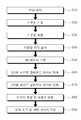
도 1은 본 발명에 따른 지중관로 내부와 지상의 3차원 정밀 측량을 통한 지리정보시스템 데이터 취득방법의 흐름을 나타낸 블록도,
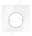
도 2는 본 발명의 일 실시예에 따른 지중관로에 타깃의 설치상태를 나타낸 도면,
도 3은 본 발명의 일 실시예에 따른 3D 레이저 스캔 측정방법을 설명하기 위한 개략도,
도 4는 본 발명에 따른 3D 레이저 스캐너로 기준점을 이용한 스캔 상태를 나타낸 도면,
도 5는 본 발명의 일 실시예에 따른 오차 체크 및 피팅 데이터 작성 완료된 3D 도면.BRIEF DESCRIPTION OF THE DRAWINGS FIG. 1 is a block diagram showing a flow of a method for acquiring a geographic information system data through a three-dimensional precision measurement of the inside of the underground channel and the ground according to the present invention;
FIG. 2 is a view illustrating an installation state of a target on an underground channel according to an embodiment of the present invention; FIG.
FIG. 3 is a schematic view for explaining a 3D laser scanning measurement method according to an embodiment of the present invention,
4 is a view illustrating a scan state using a reference point in a 3D laser scanner according to the present invention,
FIG. 5 is a 3D diagram showing an error check and fitting data creation according to an embodiment of the present invention; FIG.
이하, 본 발명에 따른 지중관로 내부와 지상의 3차원 정밀 측량을 통한 지리정보시스템 데이터 취득방법에 대한 바람직한 실시예를 첨부 도면을 참조하여 상세하게 설명한다.DETAILED DESCRIPTION OF THE PREFERRED EMBODIMENTS Hereinafter, preferred embodiments of a method for acquiring geographic information system data through three-dimensional precise surveying in the ground channel and the ground according to the present invention will be described in detail with reference to the accompanying drawings.
본 발명의 실시예는 여러 가지 형태로 변형될 수 있으며, 본 발명의 범위가The embodiments of the present invention may be modified in various forms,
아래에서 상세하게 설명하는 실시예로 한정되는 것으로 해석되어서는 아니 된다.It should not be construed as being limited to the embodiments described in detail below.
또한, 도면에서의 요소의 형상 등은 보다 명확한 설명을 강조하기 위해서 과장되어 표현될 수 있고, 각 도면에서 동일한 부재는 동일한 참조부호로 도시한 경우가 있으며, 본 발명의 요지를 불필요하게 흐릴 수 있다고 판단되는 공지 기능 및 구성에 대한 상세한 기술은 생략한다.In addition, the shapes and the like of the elements in the drawings may be exaggerated in order to emphasize a clearer explanation, and the same members in the drawings may be denoted by the same reference numerals, and the gist of the present invention may be unnecessarily blurred Detailed descriptions of known functions and configurations to be determined are omitted.
도 1은 본 발명에 따른 지중관로 내부와 지상의 3차원 정밀 측량을 통한 지리정보시스템 데이터 취득방법의 흐름을 나타낸 블록도이고, 도 2는 본 발명의 일 실시예에 따른 지중관로에 타깃의 설치상태를 나타낸 도면이며, 도 3은 본 발명의 일 실시예에 따른 3D 레이저 스캔 측정방법을 설명하기 위한 개략도이고, 도 4는 본 발명에 따른 3D 레이저 스캐너로 기준점을 이용한 스캔 상태를 나타낸 도면이며, 도 5는 본 발명의 일 실시예에 따른 오차 체크 및 피팅 데이터 작성 완료된 3D 도면이다.FIG. 1 is a block diagram showing a flow of a method for acquiring geographic information system data through three-dimensional precise measurement of the inside of the underground channel and the ground according to the present invention. FIG. 2 is a block diagram FIG. 3 is a schematic view for explaining a 3D laser scan measurement method according to an embodiment of the present invention, FIG. 4 is a view illustrating a scan state using a reference point with a 3D laser scanner according to the present invention, FIG. 5 is a 3D diagram showing an error check and fitting data creation according to an embodiment of the present invention. FIG.
본 발명에 따른 지중관로 내부와 지상의 3차원 정밀 측량을 통한 지리정보시스템 데이터 취득방법은, 도 1 내지 도 5에 도시된 것과 같이, 기존에 매설된 지중관로(10)를 측정하기 위한 현장 현황을 파악하기 위해 현장 작업구간을 사전에 답사하게 된다(S10). 이는 교통량이나 측정구간의 상황에 따라 안전 작업을 위한 기준점 측량 위치와 충격 및 간섭에 대한 안전한 타깃(target) 위치를 선정하고, 3D 레이저 스캔 위치 및 3D 레이저 스캔 기준 타깃의 위치를 결정하기 위함이다.As shown in FIGS. 1 to 5, the method for acquiring geographic information system data through three-dimensional precision measurement of the inside of the underground channel and the ground according to the present invention includes: (S10). In this case, the user is allowed to check the field work zone in advance. This is to select the reference point measurement position for safe operation and the safe target position for the shock and interference according to the traffic volume or the measurement section, and to determine the position of the 3D laser scan position and the target of the 3D laser scan reference.
이후, 상기 현장 작업구간에 지중관로(10) 내부와 지상(20)을 측정하기 위한 기준점을 선정하게 된다(S20). 이는 지중관로(10) 내부와 지상(20)에 최소 각각 3점 이상의 기준점을 설치하고, 지중관로 내부와 지상의 범위내에서 기준점에 대한 삼각망(trigonometric network, 三角網) 구성 및 상기 지중관로(10) 내부와 지상(20)의 기준점에 타깃(30)을 설치하기 위한 것이다. Then, a reference point for measuring the inside of the
상기 지중관로(10) 내부와 지상(20)을 측정하기 위한 기준점을 선정한 후, 상기 지중관로 내부와 지상을 측정하기 위한 기준점을 측량하게 된다(S30). 상기 기준점 측량은 도시는 하지 않았지만, 레이저 정밀측정기와 토탈스테이션, 위성항법장치(GPS, Global Positioning System)를 이용하여 평면(X,Y)을 관측하고, 디지털 레벨로 직접수준(Z)을 관측하여 3D 레이저 스캔 위치와 중요 대상을 측정하여 기존에 매설된 지중관로(10) 내부와 지상(20)에 대한 측량 준비를 하기 위한 것이다. 이때, 3D 레이져 스캔 측량의 기준점 측량은 전방교회법과 후방교회법 모두 사용할 수 있으며, 지중관로(10) 내부는 특성상 전방교회법은 측량한 점의 오차를 확인할 수 없는 기존의 트래버스 측량방법과 다른 점이 없으므로 후방교회법을 이용하는 것이 바람직하다.After a reference point for measuring the inside of the
상기와 같이 지중관로(10) 내부와 지상(20)을 측정하기 위한 기준점을 측량한 후, 상기 기준점에 타깃(target)(30)을 설치하게 된다(S40). 이때, 상기 타깃(30)은 도면에 스피어 볼(sphere ball) 형태(도 2 참조)로 도시되어 있으나, 시트 프리즘(sheet prism), 숫자판 등 다양한 형태로 구성될 수 있음은 물론이다. 이는 지중관로(10) 내부와 지상(20)에 대해 최소 각각 3점 이상의 기준점에 타깃(30)을 설치함으로써 후술하는 지중관로(10) 내부와 지상(20)을 3D 레이저 스캔할 때 무수한 포인트 클라우드(point cloud)로 이루어진 3차원 데이터의 정합을 위한 좌표계의 기준이 된다.After the reference point for measuring the inside of the
상기 기준점에 타깃(30)을 설치한 후, 상기 지중관로(10) 내부와 지상(20)을 각각 3D 레이저 스캔하게 된다(S50). 이때, 상기 지중관로(10) 내부와 지상(20)의 3D 레이저 스캔 순서는 바뀌어도 무방하다.After the
본 발명의 일 실시예에서는 관경 1,200㎜의 지중관로(10)를 기준으로 할 때 우선 지상(20)의 3D 레이저 스캔 측정방법에 대하여 설명한다.In an embodiment of the present invention, a 3D laser scanning measurement method of the
지리정보시스템(GIS, Geographic Information System)으로 구축된 지중관로 관망도(도시생략)에 따라 측정할 지중관로(10) 구간의 지상(20) 전체를 스캔하게 된다. 도 2 및 도 3에 도시된 바와 같이, 기준점 A-B-C 지점이 1회 스캔범위일 때 A와 C의 지점에 타깃(30)을 각각 2개씩 설치하고, B의 지점에 3D 레이저 스캐너(40)를 위치시킨 다음 스캔을 실시한다, 이때, 3D 레이저 스캐너(40)의 1회 스캔범위에 따라 스캔노이즈가 발생하므로 측정 정확도의 오차 발생을 방지하기 위해 3D 레이저 스캐너(40)의 1회 스캔범위를 약 30m 내로 하는 것이 바람직하다.The
상기와 같이 1회 스캔범위의 스캔이 완료되면, A지점의 타깃(30)을 A-B-C-D-E 지점 중, E지점으로 이동시키고 B지점에 위치한 3D 레이저 스캐너(40)를 D지점으로 자리를 이동하여 스캔을 실시한다. 이때, 측정할 지중관로(10) 구간의 지상(20) 전체에 걸쳐서 중심이 되는 각 기준점의 좌표를 소정의 정확도가 보장되도록 결정하기 위해 C지점의 타깃(30)을 움직이면 안된다. 이와 같은 방법으로 3D 레이저 스캐너의 이동을 반복하면서 측정할 지중관로(10) 구간의 지상(20)에 대해 3D 레이저 스캔을 완료한다. 이때, 3D 레이저 스캐너(40)는 스캔할 때 타깃(30)을 기준점으로 하여 360°각도로 회전을 하면서 기준점을 중심으로 10% 이상 중복 스캔하게 된다.When the scan of the one-time scan range is completed, the
상기와 같은 방법으로 지상의 3D 레이저 스캔을 완료한 후, 지중관로(10) 내부를 3D 레이저 스캔하기 전에, 지상(20)과 지중관로(10)를 연결하는 데이터 처리 작업을 할 수 있도록 지상(20)에 설치된 타깃(30) 2개와 지중관로(10)가 시작되는 입구에 타깃(30) 2개를 설치하고, 지상(20)의 타깃과 지중관로(10) 내부의 타깃(30)이 서로 보이게 설치한 후 지상(20)과 지중관로(10)가 시작되는 입구를 연결하는 3D 레이저 스캔을 실시한다.After the 3D laser scanning of the ground is completed in the same manner as described above, before the inside of the
상기와 같이 지상(20)과 지중관로(10)가 시작되는 입구를 연결하는 3D 레이저 스캔이 완료되면, 지상(20)에 있던 타깃(30)을 지중관로(10) 내부로 이동시켜 지중관로(10) 내부면에 설치한 후 지중관로(10)에 대해 3D 레이저 스캔을 실시한다. 이때, 지중관로(10)가 시작되는 입구에 설치한 타깃(30)을 움직이면 안된다.When the 3D laser scanning that connects the
지중관로(10) 3D 레이저 스캔도 지상(20) 3D 레이저 스캔과 동일한 방법으로, A-B-C 지점이 1회 스캔범위일 때 A와 C의 지점에 타깃(30)을 각각 2개씩 설치하고, B의 지점에 3D 레이저 스캐너(40)를 위치시킨 다음 스캔을 실시한다, 이때, 3D 레이저 스캔의 1회 스캔범위는 지상(20)에 비해 지중관로(10) 내부는 어둡고 빛이 없기 때문에 지상(20)의 경우보다 짧게 약 20m 내로 하는 것이 바람직하다. 또한 지중관로(10)의 특성상 타깃(30)의 자리를 이동하게 되면 기준점을 구분하기 어렵기 때문에 숫자판으로 기준점 위치에 몇 번째 스캔 작업을 실시하는지 표시해주는 것이 바람직하다. 이는 스캔 구간을 합치는 데이터 처리 작업을 할 때 용이하게 작업을 할 수 있도록 하기 위함이다.(20) In the same manner as the 3D laser scanning, two
그리고, 상기 1회 스캔범위는 지중관로(10)의 관경 크기 및 스캔 구간에 따라 변경될 수 있다.The one scan range may be changed according to the diameter of the
상기와 같이 1회 스캔범위의 스캔이 완료되면, A지점의 타깃(30)을 A-B-C-D-E 지점 중, E지점으로 이동시키고 B지점에 위치한 3D 레이저 스캐너(40)를 D지점으로 자리를 이동하여 스캔을 실시한다. 이때, 측정할 지중관로(10) 구간의 전체에 걸쳐서 중심이 되는 각 기준점의 좌표를 소정의 정확도가 보장되도록 결정하기 위해 C지점의 타깃(30)을 움직이면 안된다. 이와 같은 방법으로 3D 레이저 스캐너(40)의 이동을 반복하면서 측정할 지중관로(10)에 대해 3D 레이저 스캔을 완료한다. 이때, 3D 레이저 스캐너(40)는 스캔할 때 타깃(30)을 기준점으로 하여 360°각도로 회전을 하면서 기준점을 중심으로 10% 이상 중복 스캔하게 된다.When the scan of the one-time scan range is completed, the
상기한 3D 레이저 스캔 측정방법은, 레이저를 이용한 데이터 측정방법의 하나로, 레이져 빔을 최대 1초당 100만점 이상의 속도로 방출하여 되돌아오는 빔의 왕복시간 또는 위상차를 계산하여 X,Y,Z의 3차원 좌표성분을 1점(1 Point) 개념이 아닌 무수한 포인트 클라우드(point cloud)로 데이터를 저장하여 조사하는 측량방식이며, 이러한 무수한 데이터를 취득하여 면 데이터로 만들 수 있는 장점이 있다. 또한 대상체에 직접 측량하여 무수한 형상과 형상(또는 축)을 이용한 입체 측량이 가능할 뿐만 아니라 기준점 및 무수한 포인트 클라우드(point cloud)를 이용하여 측량 오차를 소거할 수 있으며, 무수한 형상과 형상(또는 축)을 이용한 입체 형상을 확인하는 과정에서 점과 입체면의 상태를 확인할 수 있으므로 변형된 지중관로(10)의 오차 제거가 가능하다.The 3D laser scan measurement method is a method of measuring data using a laser. The laser beam is emitted at a speed of at least one million points per second at maximum, and the reciprocating time or phase difference of the returning beam is calculated. This is a surveying method in which coordinate data is stored by counting a number of point clouds instead of a point (1 point) concept, and it is advantageous that such a large number of data can be acquired and converted into plane data. In addition, it is possible to perform direct measurement on a target object and to perform a three-dimensional measurement using a number of shapes and shapes (or axes), as well as erase a measurement error using a reference point and a myriad point cloud, The state of the point and the solid surface can be confirmed in the process of confirming the three-dimensional shape by using the deformed
또한 도 4에 도시된 바와 같이, 3D 레이저 스캐너(40)로 기준점이 보이는 위치에 최소 3점 이상의 기준점(타깃)을 이용하여 스캔함으로써, 기존의 기계설치 측량에 의해 측량한 점의 오차를 확인할 수 없는 트래버스(travers) 측량에 의한 지중관로의 측정 오차 제거가 가능하고, 기준점 상태도 직접 파악이 가능하여 더욱 정밀한 입체 측량을 할 수 있게 된다.Also, as shown in FIG. 4, by using a reference point (target) of at least three points at the position where the reference point is visible to the
상기와 같이 3D 레이저 스캔하게 되면서 측정할 전체 구간에 대하여 3차원 포인트 클라우드 데이터를 취득하게 된다(S60). 이때, 포인트 밀도 10m : 1㎝×1㎝의 면 데이터를 취득하게 되며, 측정한 데이터는 각 포인트의 좌표, 인텐시티(intensity) 및 RGB 값 등이 있다. 또한 다른 데이터 포맷으로 변환(DXF, DGN, XYZ, NEZ, TXT, PTX, ASCII 등)이 가능하고, 측정한 데이터를 후처리하여 3차원으로 설계된 모델 값과 비교하여 측정대상을 검사하거나 역설계(Revers Engineering)를 할 수 있는 자료를 제공할 수 있다.3D laser scanning is performed as described above, and three-dimensional point cloud data is acquired for the whole section to be measured (S60). At this time, surface data of a point density of 10 m: 1 cm x 1 cm is acquired. The measured data includes the coordinates, intensity, and RGB values of each point. It can also convert to other data format (DXF, DGN, XYZ, NEZ, TXT, PTX, ASCII etc.) Revers Engineering can be provided.
상기와 같이 3차원 포인트 클라우드 데이터를 취득한 후 3차원 포인트 클라우드 데이터를 입력하게 된다(S70). 이때, 포인트 수에 관계없이 무한데이터가 입력된다.After acquiring the three-dimensional point cloud data as described above, the three-dimensional point cloud data is input (S70). At this time, infinite data is input irrespective of the number of points.
다음으로, 상기 입력된 3차원 포인트 클라우드 데이터를 정합하고 좌표계로 변환하게 된다(S80). 이는 3차원 포인트 클라우드 데이터 정합과 수치지도이용을 위한 국가좌표계 변환에 의해 지상과 지중관로의 3차원 좌표 위치 데이터를 얻을 수 있다.Next, the input 3D point cloud data is matched and converted into a coordinate system (S80). It can obtain 3-D coordinate position data of ground and underground pipeline by transforming the national coordinate system for 3D point cloud data matching and numerical map utilization.
상기와 같이 3차원 포인트 클라우드 데이터를 정합하고 좌표계로 변환한 후, 상기 3차원 포인트 클라우드 데이터 정합과 좌표계 변환의 오차를 체크하고 피팅 데이터(fitting data)를 작성하게 된다(S90). 이는 기준점의 오차를 조정하여 정확한 측량 성과를 취득할 수 있도록 하여 지중관로(10)의 정확한 정보를 제공할 수 있도록 하고, 피팅 데이터는 3D 모델링 된 데이터를 표준형식의 파일로 데이터 베이스에 저장하는데 제공되고, 3D 출력이 가능한 STL 파일로 변환하여 지리정보시스템(GIS, Geographic Information System)과 일치시켜 지중관로 관망도를 구축하는데 활용할 수 있도록 하기 위함이다.The three-dimensional point cloud data is matched and transformed into the coordinate system as described above, and the error of the three-dimensional point cloud data matching and the coordinate system conversion is checked and fitting data is created (S90). This makes it possible to provide accurate information of the
따라서, 본 발명은 지중관로(10) 내부와 지상(20)을 기준점에 설치된 타깃(30)과 3D 레이저 스캐너(40)를 이용한 3차원 정밀 측량을 통해 오차 발생을 소거하여 지중관로(10)의 곡률 및 곡관, 내경, 위치 및 파손상태를 정확하게 파악할 수 있고, 그로 인하여 관로에 포설되는 목적물의 포설조건을 검토할 수 있는 지리정보시스템의 데이터로 활용할 수 있으므로 지중관로(10)의 파손이 발생하였을 때 신속하게 손상부위를 수리하여 지중관로(10)의 형상을 복원할 수 있는 이점이 있다.Therefore, the present invention can eliminate the occurrence of errors by performing three-dimensional precision measurement inside the
또한, 3D 레이저 스캐너(40)로 지중관로(10) 표면의 재질감까지 스캔하였기 때문에 정확한 3차원 모델링 작성이 가능하여 지중관로(10)의 탐지하지 못한 관로의 탐지를 가능하게 하고, 지중관로(10)를 보수할 때 도면이 없더라도 신속하게 도면을 복원하여 지중관로(10)를 보수할 수 있을 뿐만 아니라 지중관로(10) 정보에 대한 오차 발생을 소거하여 종래에 구축된 지리정보시스템의 위치 오차 보정을 가능하게 하며, BIM(Building Information Modeling)에 접목하여 보다 효율적으로 활용할 수 있도록 하는 이점이 있다.Since the
이상과 같이 본 발명의 바람직한 실시예에 대해 첨부된 도면을 참조로 하여 설명하였으나, 본 발명은 상술한 특정의 실시예에 의해 한정되는 것이 아니며, 본 발명이 속하는 기술분야에서 통상의 지식을 가진 자에 의해 본 발명의 기술적 사상과 이하에서 기재되는 특허청구범위의 균등범위 내에서 다양한 형태의 수정 및 변형이 가능함은 물론이다.While the present invention has been particularly shown and described with reference to exemplary embodiments thereof, it is clearly understood that the same is by way of illustration and example only and is not to be construed as limited to the particular details of the embodiments set forth herein. It will be understood by those skilled in the art that various changes in form and details may be made therein without departing from the spirit and scope of the present invention as defined by the appended claims.
10 : 지중관로 20 : 지상
30 : 타깃 40 : 3D 레이저 스캐너10: Underground pipeline 20: Ground
30: Target 40: 3D laser scanner
Claims (5)
Translated fromKorean상기 현장 작업구간에 지중관로 내부와 지상을 측정하기 위한 기준점을 선정하는 단계(S20);
상기 지중관로 내부와 지상을 측정하기 위한 기준점을 측량하는 단계(S30);
상기 기준점에 타깃을 설치하는 단계(S40);
상기 지중관로 내부와 지상을 3D 레이저 스캔하는 단계(S50);
상기 3D 레이저 스캔하여 3차원 포인트 클라우드(point cloud) 데이터를 취득하는 단계(S60);
상기 3차원 포인트 클라우드로 데이터를 입력하는 단계(S70);
상기 입력된 3차원 포인트 클라우드 데이터 정합 및 좌표계로 변환하는 단계(S80); 및
상기 3차원 포인트 클라우드 데이터 정합과 좌표계 변환의 오차 체크 및 피팅 데이터(fitting data)를 작성하는 단계(S90);
를 포함하는 지중관로 내부와 지상의 3차원 정밀 측량을 통한 지리정보시스템 데이터 취득방법.(S10) of exploring a field work zone in advance to grasp the current state of the field for measuring an existing underground channel;
(S20) of selecting a reference point for measuring the inside and the ground of the underground pipe in the field work section;
Measuring a reference point for measuring the inside and the ground of the underground pipe (S30);
Installing a target at the reference point (S40);
(S50) a 3D laser scan of the inside of the underground pipe and the ground;
Acquiring three-dimensional point cloud data by the 3D laser scanning (S60);
Inputting data into the 3D point cloud (S70);
Transforming the input three-dimensional point cloud data into a coordinate and a coordinate system (S80); And
A step (S90) of checking the error of the three-dimensional point cloud data matching and the coordinate system conversion and fitting data;
A method for acquiring geographic information system data through three-dimensional precision measurement inside and on the ground including an underground channel.
상기 기준점은 지상과 지중관로 내부에 최소 각각 3점 이상 설치하는 것을 특징으로 하는 지중관로 내부와 지상의 3차원 정밀 측량을 통한 지리정보시스템 데이터 취득방법.The method according to claim 1,
Wherein the reference point is installed at least three points in the ground and at least three in the underground pipe, respectively.
상기 지중관로 내부와 지상을 3D 레이저 스캔하는 단계(S50)에서, 1회 스캔범위는 각 단계별로 10% 이상의 중복 데이터를 획득하는 것을 특징으로 하는 지중관로 내부와 지상의 3차원 정밀 측량을 통한 지리정보시스템 데이터 취득방법.The method according to claim 1,
Wherein the step of scanning the inside of the underground pipe with the 3D laser scanning of the ground (S50) acquires at least 10% redundant data for each step in one scan range. Information system data acquisition method.
상기 지중관로 내부와 지상을 3D 레이저 스캔하는 단계(S50)에서, 지상의 3D 레이저 스캔을 완료한 후, 지중관로 내부를 3D 레이저 스캔하기 전에, 지상에 설치된 타깃 2개와 지중관로가 시작되는 입구에 타깃 2개를 설치하고, 상기 지상의 타깃과 지중관로 내부의 타깃이 서로 보이게 설치한 후 지상과 지중관로가 시작되는 입구를 연결하는 3D 레이저 스캔을 실시하는 것을 특징으로 하는 지중관로 내부와 지상의 3차원 정밀 측량을 통한 지리정보시스템 데이터 취득방법.The method according to claim 1,
In the 3D laser scanning of the inside of the underground pipe and the ground (S50), before the 3D laser scan of the inside of the underground pipe after completing the 3D laser scan of the ground, two targets installed on the ground and an entrance where the underground pipe starts And a target is placed in the ground and the target in the underground pipe is installed so as to be visible to each other. Then, a 3D laser scan is performed to connect the ground and the entrance where the underground channel starts. A method of acquiring geographic information system data through three - dimensional precision surveying.
상기 지중관로 내부의 타깃 위치에 3D 레이저 스캔 순서에 따라 숫자판으로 표시하는 것을 특징으로 하는 지중관로 내부와 지상의 3차원 정밀 측량을 통한 지리정보시스템 데이터 취득방법.5. The method of claim 4,
And displaying the target position inside the underground pipe in the form of a number plate according to a 3D laser scanning order.
Priority Applications (1)
| Application Number | Priority Date | Filing Date | Title |
|---|---|---|---|
| KR1020150055810AKR101624705B1 (en) | 2015-04-21 | 2015-04-21 | Method acquire geographic information system data through a three-dimensional precision measurements of underground pipeline inside the ground |
Applications Claiming Priority (1)
| Application Number | Priority Date | Filing Date | Title |
|---|---|---|---|
| KR1020150055810AKR101624705B1 (en) | 2015-04-21 | 2015-04-21 | Method acquire geographic information system data through a three-dimensional precision measurements of underground pipeline inside the ground |
Publications (1)
| Publication Number | Publication Date |
|---|---|
| KR101624705B1true KR101624705B1 (en) | 2016-05-26 |
Family
ID=56104882
Family Applications (1)
| Application Number | Title | Priority Date | Filing Date |
|---|---|---|---|
| KR1020150055810AActiveKR101624705B1 (en) | 2015-04-21 | 2015-04-21 | Method acquire geographic information system data through a three-dimensional precision measurements of underground pipeline inside the ground |
Country Status (1)
| Country | Link |
|---|---|
| KR (1) | KR101624705B1 (en) |
Cited By (12)
| Publication number | Priority date | Publication date | Assignee | Title |
|---|---|---|---|---|
| CN106595525A (en)* | 2016-12-26 | 2017-04-26 | 中国矿业大学(北京) | Three-dimensional-point-cloud-data-based prevention method of coal mine roof disaster |
| KR101863188B1 (en)* | 2017-10-26 | 2018-06-01 | (주)아세아항측 | Method for construction of cultural heritage 3D models |
| KR20200087330A (en)* | 2018-12-28 | 2020-07-21 | 네이버시스템(주) | State information analysis and modelling method of sewerage pipe |
| KR102178908B1 (en)* | 2019-12-26 | 2020-11-13 | 주식회사 지오비전 | Analytical system for finding pipelines from gpr 3d-data |
| KR102205080B1 (en)* | 2019-12-30 | 2021-01-20 | (주)코아텍 | Method for process of gpr data |
| KR102210344B1 (en)* | 2020-07-09 | 2021-02-01 | 주식회사 우리아이씨티 | Method for producing digital topography using 3D precision scanner-based field survey and complementary survey |
| CN114332005A (en)* | 2021-12-27 | 2022-04-12 | 重庆市工程管理有限公司 | Large-pipe-diameter rainwater and sewage pipe network damage detection method based on BIM point cloud technology |
| CN115423970A (en)* | 2022-08-17 | 2022-12-02 | 武汉中仪物联技术股份有限公司 | Pipeline scanning method and device, electronic equipment and storage medium |
| WO2022252390A1 (en)* | 2021-06-01 | 2022-12-08 | 新石器慧通(北京)科技有限公司 | Error compensation method and apparatus, computer device, and storage medium |
| CN115615324A (en)* | 2022-10-20 | 2023-01-17 | 中国电建集团西北勘测设计研究院有限公司 | A three-dimensional laser scanning detection method for drainage pipes |
| CN117540511A (en)* | 2023-10-12 | 2024-02-09 | 中交建筑集团有限公司 | A pipeline management and control method and system based on BIM modeling |
| CN119378173A (en)* | 2024-12-25 | 2025-01-28 | 浙江莱普顿管道科技有限公司 | A water pipe intelligent processing method and system based on BIM |
Citations (2)
| Publication number | Priority date | Publication date | Assignee | Title |
|---|---|---|---|---|
| KR100974881B1 (en) | 2009-12-10 | 2010-08-11 | (주)다인디지컬처 | Method for rubbing copy with the three-dimension scanning |
| KR101379400B1 (en) | 2012-12-03 | 2014-03-28 | 연세대학교 산학협력단 | Production method of completed building drawing using 3d laser scanner |
- 2015
- 2015-04-21KRKR1020150055810Apatent/KR101624705B1/enactiveActive
Patent Citations (2)
| Publication number | Priority date | Publication date | Assignee | Title |
|---|---|---|---|---|
| KR100974881B1 (en) | 2009-12-10 | 2010-08-11 | (주)다인디지컬처 | Method for rubbing copy with the three-dimension scanning |
| KR101379400B1 (en) | 2012-12-03 | 2014-03-28 | 연세대학교 산학협력단 | Production method of completed building drawing using 3d laser scanner |
Cited By (13)
| Publication number | Priority date | Publication date | Assignee | Title |
|---|---|---|---|---|
| CN106595525A (en)* | 2016-12-26 | 2017-04-26 | 中国矿业大学(北京) | Three-dimensional-point-cloud-data-based prevention method of coal mine roof disaster |
| KR101863188B1 (en)* | 2017-10-26 | 2018-06-01 | (주)아세아항측 | Method for construction of cultural heritage 3D models |
| KR20200087330A (en)* | 2018-12-28 | 2020-07-21 | 네이버시스템(주) | State information analysis and modelling method of sewerage pipe |
| KR102170235B1 (en) | 2018-12-28 | 2020-10-26 | 네이버시스템(주) | State information analysis and modelling method of sewerage pipe |
| KR102178908B1 (en)* | 2019-12-26 | 2020-11-13 | 주식회사 지오비전 | Analytical system for finding pipelines from gpr 3d-data |
| KR102205080B1 (en)* | 2019-12-30 | 2021-01-20 | (주)코아텍 | Method for process of gpr data |
| KR102210344B1 (en)* | 2020-07-09 | 2021-02-01 | 주식회사 우리아이씨티 | Method for producing digital topography using 3D precision scanner-based field survey and complementary survey |
| WO2022252390A1 (en)* | 2021-06-01 | 2022-12-08 | 新石器慧通(北京)科技有限公司 | Error compensation method and apparatus, computer device, and storage medium |
| CN114332005A (en)* | 2021-12-27 | 2022-04-12 | 重庆市工程管理有限公司 | Large-pipe-diameter rainwater and sewage pipe network damage detection method based on BIM point cloud technology |
| CN115423970A (en)* | 2022-08-17 | 2022-12-02 | 武汉中仪物联技术股份有限公司 | Pipeline scanning method and device, electronic equipment and storage medium |
| CN115615324A (en)* | 2022-10-20 | 2023-01-17 | 中国电建集团西北勘测设计研究院有限公司 | A three-dimensional laser scanning detection method for drainage pipes |
| CN117540511A (en)* | 2023-10-12 | 2024-02-09 | 中交建筑集团有限公司 | A pipeline management and control method and system based on BIM modeling |
| CN119378173A (en)* | 2024-12-25 | 2025-01-28 | 浙江莱普顿管道科技有限公司 | A water pipe intelligent processing method and system based on BIM |
Similar Documents
| Publication | Publication Date | Title |
|---|---|---|
| KR101624705B1 (en) | Method acquire geographic information system data through a three-dimensional precision measurements of underground pipeline inside the ground | |
| Wang et al. | Applications of terrestrial laser scanning for tunnels: a review | |
| Costello et al. | Underground asset location and condition assessment technologies | |
| KR101179001B1 (en) | System for measuring position and management of buried structures | |
| KR101944823B1 (en) | Underground Facilities Detection System Using Augmented Reality and Virtual Reality | |
| KR101306882B1 (en) | Information Acquisition Method And Device For Underground Utilities | |
| EP3510424B1 (en) | Pipeline mapping system | |
| KR102478341B1 (en) | Underground burial management system that can build a three-dimensional underground space map | |
| KR101918486B1 (en) | underground utilities information acquisition apparatus based on big-data for exploring a composite pipe using resistivity, and the method thereof | |
| CN106546877A (en) | A kind of Method of Cable Trouble Point accurate positioning method based on curve matching | |
| KR101173161B1 (en) | Exploration measurement system of underground conduit line | |
| CN115291200B (en) | Digital display-based buried pipeline positioning method | |
| JP2022553750A (en) | Method for detecting infrastructure elements of an underground network and its mobile detector | |
| KR102207792B1 (en) | Apparatus for modeling 3d of underground structure and method thereof | |
| JP6478578B2 (en) | Exploration equipment | |
| KR102095799B1 (en) | Apparatus for mapping buried object and ground cavity through electromagneticwave analysis | |
| CN103697844A (en) | Oil and gas pipeline center line coordinate correcting method based on internal inspection | |
| KR101388131B1 (en) | Detecting system for underground pipes using electric field | |
| Gabryś et al. | GPR surveying method as a tool for geodetic verification of GESUT database of utilities in the light of BSI PAS128 | |
| JP2008076907A (en) | A method for obtaining a three-dimensional profile of a pipeline, a method for specifying a buried position of a pipeline, and a method for specifying a defect position of a pipeline | |
| CN103765246A (en) | Apparatus and method for non-invasive real-time subsoil inspection | |
| KR101943426B1 (en) | Method, apparatus, computer program and computer readable recording medium for generating a drawing of an inner wall condition of a conduit, method, apparatus, computer program and computer readable recording medium for inspecting an inner wall condition of a conduit | |
| CN117805229A (en) | Long-distance pipeline magnetic leakage inner detection corrosion defect point excavation positioning method based on double-side projection correction method | |
| KR101209285B1 (en) | Surveying data control system for the surface of the earth checking datumpoint and benchmark | |
| KR101173166B1 (en) | Exploration measurement measure of underground conduit line |
Legal Events
| Date | Code | Title | Description |
|---|---|---|---|
| PA0109 | Patent application | Patent event code:PA01091R01D Comment text:Patent Application Patent event date:20150421 | |
| PA0201 | Request for examination | ||
| E701 | Decision to grant or registration of patent right | ||
| PE0701 | Decision of registration | Patent event code:PE07011S01D Comment text:Decision to Grant Registration Patent event date:20160513 | |
| GRNT | Written decision to grant | ||
| PR0701 | Registration of establishment | Comment text:Registration of Establishment Patent event date:20160520 Patent event code:PR07011E01D | |
| PR1002 | Payment of registration fee | Payment date:20160520 End annual number:3 Start annual number:1 | |
| PG1601 | Publication of registration | ||
| PR1001 | Payment of annual fee | Payment date:20200506 Start annual number:5 End annual number:5 | |
| PR1001 | Payment of annual fee | Payment date:20210429 Start annual number:6 End annual number:6 | |
| PR1001 | Payment of annual fee | Payment date:20230427 Start annual number:8 End annual number:8 | |
| PR1001 | Payment of annual fee | Payment date:20240430 Start annual number:9 End annual number:9 | |
| PR1001 | Payment of annual fee | Payment date:20250430 Start annual number:10 End annual number:10 |