KR101622772B1 - Self-assembly drawer - Google Patents
Self-assembly drawerDownload PDFInfo
- Publication number
- KR101622772B1 KR101622772B1KR1020150157875AKR20150157875AKR101622772B1KR 101622772 B1KR101622772 B1KR 101622772B1KR 1020150157875 AKR1020150157875 AKR 1020150157875AKR 20150157875 AKR20150157875 AKR 20150157875AKR 101622772 B1KR101622772 B1KR 101622772B1
- Authority
- KR
- South Korea
- Prior art keywords
- protrusion
- present
- depression
- width
- cover panel
- Prior art date
- Legal status (The legal status is an assumption and is not a legal conclusion. Google has not performed a legal analysis and makes no representation as to the accuracy of the status listed.)
- Expired - Fee Related
Links
Images


Classifications
- A—HUMAN NECESSITIES
- A47—FURNITURE; DOMESTIC ARTICLES OR APPLIANCES; COFFEE MILLS; SPICE MILLS; SUCTION CLEANERS IN GENERAL
- A47B—TABLES; DESKS; OFFICE FURNITURE; CABINETS; DRAWERS; GENERAL DETAILS OF FURNITURE
- A47B47/00—Cabinets, racks or shelf units, characterised by features related to dismountability or building-up from elements
- A47B47/0075—Flat or flat-like panels connected without frames
- A—HUMAN NECESSITIES
- A47—FURNITURE; DOMESTIC ARTICLES OR APPLIANCES; COFFEE MILLS; SPICE MILLS; SUCTION CLEANERS IN GENERAL
- A47B—TABLES; DESKS; OFFICE FURNITURE; CABINETS; DRAWERS; GENERAL DETAILS OF FURNITURE
- A47B47/00—Cabinets, racks or shelf units, characterised by features related to dismountability or building-up from elements
- A47B47/0025—Horizontal connecting members adapted to receive and retain the edges of several panel elements
- A—HUMAN NECESSITIES
- A47—FURNITURE; DOMESTIC ARTICLES OR APPLIANCES; COFFEE MILLS; SPICE MILLS; SUCTION CLEANERS IN GENERAL
- A47B—TABLES; DESKS; OFFICE FURNITURE; CABINETS; DRAWERS; GENERAL DETAILS OF FURNITURE
- A47B2230/00—Furniture jointing; Furniture with such jointing
- A47B2230/0074—Mortise and tenon joints or the like including some general male and female connections
Landscapes
- Details Of Rigid Or Semi-Rigid Containers (AREA)
Abstract
Translated fromKoreanDescription
Translated fromKorean본 발명은 수납함에 관한 것으로, 보다 상세하게는 바닥부, 후면부, 측면부, 상면부 및 전면부를 사용자가 임의대로 조합하여 원하는 형태로 조립할 수 있으므로 공간 활용성이 향상되고 다양한 용도로 활용될 수 있는 조립식 수납함에 관한 것이다.
BACKGROUND OF THE INVENTION 1. Field of the Invention The present invention relates to a storage box, and more particularly, to a storage box, which can be assembled in a desired shape by arbitrarily combining a bottom portion, a rear portion, a side portion, The present invention relates to a storage box.
일반적으로 수납함은 각종 소도구나 의류 등 가정에서 자주 사용하는 다양한 물품을 간편하게 보관하기 위한 것으로서, 사용자는 수납함에 물품을 보관하여 집안을 깔끔하게 정리정돈할 수 있다.Generally, the storage box is for easily storing a variety of items frequently used at home, such as various props and clothes, and the user can store the items in a storage box and arrange the house neatly.
통상적으로 이러한 목재나 철재 또는 플라스틱으로 이루어지고, 고정된 케이스의 내부에 다수의 수납공간이 상하방향 또는 좌우방향으로 적층되어 분할된 구조를 가지게 된다.Typically, such a structure is made of wood, steel or plastic, and has a structure in which a plurality of storage spaces are stacked in a vertical direction or in a left-right direction and divided into a fixed case.
그러나 종래 수납함은 무겁고 그 형상 변경이 불가능하여 사용자가 새로운 용도로 수납함을 활용하고자 하는 경우 또는 이사를 하여서 설치 공간이 바뀌는 등의 경우, 고가의 수납함을 돈을 들여 폐기하고 새로운 수납함을 구매하여야 하는 문제점이 있다.However, conventionally, when the storage box is heavy and its shape can not be changed, when the user intends to utilize the storage box for a new purpose or when the installation space is changed by moving, the expensive storage box must be discarded and the new storage box must be purchased .
또한, 종래 수납함은 이동 시 또는 구입 시, 사용자의 승용차를 이용해 옮기기에는 차지하는 부피가 커서 사용자들이 많은 운반비나 물류비를 지불하고 있는 실정이다.In addition, the conventional storage box has a large volume to be moved by using a passenger car at the time of moving or at the time of purchase, so that users pay a lot of transportation costs and logistics costs.
나아가, 이러한 문제점을 해결하고자 조립식 수납함이 일부 개발되고 있으나, 대부분은 전문 지식이 있는 사람이 특수한 형태의 공구를 이용하여 조립하거나 해체하여야 수납함이 조립되므로 일반인 혹은 가정 주부들이 수납함을 해체하거나 재조립하는 것은 거의 불가능하다는 문제점이 있다.In addition, some prefabricated storage boxes have been developed to solve these problems, but most of them are assembled or disassembled by a special type of tool, so that ordinary people or housewives can disassemble or reassemble the storage box There is a problem that it is almost impossible.
상기의 배경기술로서 설명된 사항들은 본 발명의 배경에 대한 이해 증진을 위한 것일 뿐, 이 기술분야에서 통상의 지식을 가진자에게 이미 알려진 종래기술에 해당함을 인정하는 것으로 받아들여져서는 안 될 것이다.
It should be understood that the foregoing description of the background art is merely for the purpose of promoting an understanding of the background of the present invention and is not to be construed as an admission that the prior art is known to those skilled in the art.
본 발명은 전술한 종래기술의 문제점을 해결하기 위해 안출된 것으로서, 사용자가 원하는 형태로 조립할 수 있으므로 공간 활용성이 극대화되고 운반 시 부피를 최소화할 수 있는 조립식 수납함을 제공하는데 그 목적이 있다.SUMMARY OF THE INVENTION It is an object of the present invention to provide a prefabricated cabinet that can maximize space utilization and minimize volume during transportation because the user can assemble the package in a desired form.
또한, 본 발명은 별도의 조립 공구 없이 각 부품을 조립하여 수납함을 만들 수 있으므로 원하는 장소에서 누구든지 쉽게 해체 또는 재조립 작업을 할 수 있는 조립식 수납함을 제공하는데 또 다른 목적이 있다.It is another object of the present invention to provide an assembly-type storage box which can easily disassemble or reassemble anyone in a desired place because each component can be assembled and assembled without a separate assembly tool.
본 발명이 이루고자 하는 기술적 과제들은 이상에서 언급한 기술적 과제들로 제한되지 않으며, 언급되지 않은 또 다른 기술적 과제들은 본 발명의 기재로부터 당해 분야에서 통상의 지식을 가진 자에게 명확하게 이해될 수 있을 것이다.
The technical objects to be achieved by the present invention are not limited to the above-mentioned technical problems, and other technical subjects which are not mentioned can be clearly understood by those skilled in the art from the description of the present invention .
상기와 같은 목적을 달성하기 위한 본 발명의 구성은, 모서리와 중앙부를 따라 '┌┐' 형상의 돌출부와 '└┘' 형상의 함몰부가 교대로 형성되며, 상기 돌출부와 함몰부의 일측에는 각각 돌출삽입부와 함몰삽입부가 천공되는 바닥부; 상기 바닥부의 후면 모서리에 형성된 함몰부의 상면과 돌출부의 하면에 각각 삽입가능하도록 다수의 서로 이격된 제1후면융기부와 제2후면융기부가 형성되고, 상기 제1후면융기부와 제2후면융기부의 끝단에는 각각 함몰삽입부와 돌출삽입부에 삽입되는 제1후면돌기와 제2후면돌기가 돌출되는 후면부; 상기 바닥부의 측면 모서리 또는 중앙부에 형성된 함몰부의 상면과 돌출부의 하면에 각각 삽입가능하도록 다수의 서로 이격된 제1측면융기부와 제2측면융기부가 형성되고, 상기 제1측면융기부와 제2측면융기부의 끝단에는 각각 함몰삽입부와 돌출삽입부에 삽입되는 제1측면돌기와 제2측면돌기가 돌출되는 측면부; 모서리와 중앙부를 따라 상기 제2후면돌기 및 제2측면돌기가 삽입될 수 있도록 다수의 삽입홀이 천공되는 상면부; 및 상기 바닥부의 전면과 힌지핀 및 힌지홀더를 매개로 회동 가능하도록 연결되는 전면부; 를 포함하는 것을 특징으로 한다.According to an aspect of the present invention, there is provided a semiconductor device comprising: a semiconductor substrate having a plurality of protrusions and a plurality of depressions formed along corners and a central portion, A bottom portion in which the portion and the recessed insertion portion are perforated; A plurality of first rear ridges and second rear ridges spaced apart from each other so as to be respectively insertable into the upper surface of the depression formed at the rear edge of the bottom portion and the lower surface of the protruding portion are formed and the first rear ridge portion and the second rear ridge portion A rear portion protruding from the rear end of the first rear protrusion and the second rear protrusion inserted into the recess insertion portion and the protrusion insertion portion, respectively; A plurality of first side surface raised portions and a second side surface raised portions are formed so as to be respectively insertable into the upper surface of the depressed portion formed at the side edge or the central portion of the bottom portion and the lower surface of the projecting portion, And a side surface protruding from the tip of the ridge portion, the first side surface protrusion and the second side surface protrusion being inserted into the depression insertion portion and the protrusion insertion portion, respectively; An upper surface portion in which a plurality of insertion holes are perforated so that the second rear protrusions and the second side surface protrusions can be inserted along corners and a central portion; And a front part rotatably connected to a front surface of the bottom part via a hinge pin and a hinge holder; And a control unit.
또한, 본 발명의 실시예에 따른 조립식 수납함에서 상기 바닥부에 형성된 돌출부의 높이와 함몰부의 깊이는 동일하게 형성되며, 돌출부의 마주보는 양 측면과 함몰부의 마주보는 양 측면은 미리 정해진 각도로 경사면이 각각 형성되는 것이 바람직하다.The height of the protrusion formed on the bottom portion and the depth of the depression are formed to be equal to each other in the assembled type storage box according to the embodiment of the present invention. The opposite side surfaces of the protrusion and the opposite side surfaces of the depression portion are inclined at predetermined angles Respectively.
아울러, 본 발명의 실시예에 따른 조립식 수납함에서 상기 바닥부의 하면에는 정육각형 형태로 돌출된 다수의 바닥리브가 형성되는 것이 바람직하다.In addition, in the assembled type storage box according to the embodiment of the present invention, a plurality of bottom ribs protruding in the form of a regular hexagon may be formed on the bottom surface of the bottom portion.
또한, 본 발명의 일실시예에 따른 조립식 수납함에서 상기 후면부에 형성된 제1후면돌기와 제2후면돌기는 후크 형태로 이루어져 각각 함몰삽입부와 돌출삽입부에 삽입과 동시에 걸려서 후면부의 유격을 제한하는 것이 바람직하고, 상기 후면부에 형성된 제1후면융기부의 폭은 함몰부의 폭과 동일하고, 제2후면융기부의 폭은 돌출부의 폭과 동일한 것이 바람직하다.The first and second rear projections and the second rear protrusions formed on the rear portion of the assembled receptacle according to an embodiment of the present invention are hooked to be engaged with the recessed insertion portion and the protrusion insertion portion at the same time to limit the clearance of the rear portion Preferably, the width of the first rear elevated portion formed on the rear portion is equal to the width of the depressed portion, and the width of the second rear elevated portion is equal to the width of the protruded portion.
또한, 본 발명의 실시예에 따른 조립식 수납함에서 상기 측면부에 형성된 제1측면돌기와 제2측면돌기는 후크 형태로 이루어져 각각 함몰삽입부와 돌출삽입부에 삽입과 동시에 걸려서 측면부의 유격을 제한하는 것이 바람직하고, 상기 측면부에 형성된 제1측면융기부의 폭은 함몰부의 폭과 동일하고, 제2측면융기부의 폭은 돌출부의 폭과 동일한 것이 바람직하다.The first side surface protrusion and the second side surface protrusion formed on the side portion of the assembled type storage box according to an embodiment of the present invention are formed in a hook shape and are preferably engaged with the depression insertion portion and the protrusion insertion portion at the same time to limit the clearance of the side portion The width of the first side raised portion formed on the side portion is equal to the width of the depressed portion, and the width of the second side raised portion is equal to the width of the protruded portion.
한편, 본 발명의 실시예에 따른 조립식 수납함에서 상기 측면부의 일측면에는 상하방향으로 길게 슬라이더가 돌출 형성되고, 상기 후면부에는 슬라이더가 활주할 수 있도록 활주홈이 상하방향으로 길게 형성되어 측면부와 후면부가 상호 연결되는 것이 바람직하다.In the assembled type storage box according to an embodiment of the present invention, a slider is protruded in a vertical direction on one side surface of the side portion, and a slide groove is formed to be long in the vertical direction so that the slider can slide on the rear portion, It is preferable that they are interconnected.
또한, 본 발명의 실시예에 따른 조립식 수납함에서 상기 상면부의 하면에는 정육각형 형태로 돌출된 다수의 상면리브가 형성되는 것이 바람직하며, 상기 힌지핀은, 상기 전면부의 일측에 형성된 다각형 통부에 삽입될 수 있도록 다각형 단면을 가지는 제1삽입핀; 및 상기 힌지홀더에 회전 가능하도록 삽입되는 원통형의 제2삽입핀; 을 포함하는 것이 좋다.It is preferable that a plurality of upper surface ribs protruding in the shape of a regular hexagon are formed on the lower surface of the upper surface portion of the assembled type storage box according to the embodiment of the present invention. The hinge pin may be inserted into the polygonal tube portion formed on one side of the front surface portion. A first insert pin having a polygonal cross section; And a cylindrical second insertion pin rotatably inserted into the hinge holder; .
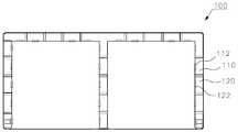
나아가, 본 발명의 실시예에 따른 조립식 수납함은, 상면 또는 하면 중 하나의 면은 막혀있고, 다른 하나의 면은 상기 전면부의 상단 또는 하단이 삽입될 수 있도록 개방되어 있으며, 일측에 핸들이 삽입될 수 있도록 핸들삽입구가 형성된 제1커버패널; 을 더 포함하는 것이 바람직하다.Further, in the assembled type storage box according to the embodiment of the present invention, one surface of the upper surface or the lower surface is clogged, and the other surface is opened to allow the upper or lower end of the front surface portion to be inserted, A first cover panel having a handle insertion hole formed therein so as to allow the first cover panel; .
또한, 본 발명의 실시예에 따른 조립식 수납함은, 상면 또는 하면 중 하나의 면은 막혀있고, 다른 하나의 면은 상기 전면부의 상단 또는 하단이 삽입될 수 있도록 개방되어 있는 제2커버패널; 을 더 포함하는 것이 바람직하다.A second type of cover panel according to an embodiment of the present invention includes a second cover panel in which one surface of the upper surface or the lower surface is clogged and the other surface is opened to allow the upper or lower end of the front surface portion to be inserted; .
또한, 본 발명의 실시예에 따른 조립식 수납함은, 상기 전면부의 상단 또는 하단이 삽입될 수 있도록 상면과 하면 모두 개방되어 있으며, 일측에 핸들이 삽입될 수 있도록 핸들삽입구가 형성된 제3커버패널; 을 더 포함하는 것이 바람직하다.In addition, the assembly type storage box according to an embodiment of the present invention includes: a third cover panel having an upper surface and a lower surface so that an upper end or a lower end of the front part can be inserted, and a handle insertion port for inserting a handle into one side; .
아울러, 본 발명의 실시예에 따른 조립식 수납함은, 상기 바닥부의 하면 모퉁이에 형성된 다수의 제1관부; 및 상기 제1관부에 삽입될 수 있도록 한 쌍의 제1플러그가 돌출된 제1발; 을 더 포함하는 것이 바람직하다.In addition, the prefabricated storage box according to an embodiment of the present invention includes: a plurality of first tube portions formed on a bottom corner of the bottom portion; And a pair of first plugs protruding from the first tube so as to be inserted into the first tube portion; .
또한, 본 발명의 실시예에 따른 조립식 수납함은, 상기 바닥부의 하면 중앙부에 형성된 다수의 제2관부; 및 상기 제2관부에 삽입될 수 있도록 4개의 제2플러그가 돌출된 제2발; 을 더 포함하는 것이 바람직하다.
In addition, the assembled type storage box according to the embodiment of the present invention includes: a plurality of second tube portions formed at the center of the bottom of the bottom portion; And a second foot having four second plugs protruded to be inserted into the second tube portion; .
상기와 같은 구성을 가지는 본 발명은, 사용자가 원하는 형태로 수납함을 조립할 수 있으므로 원하는 공간에 맞추어 새로운 제품을 구입하지 않고도 공간을 최대한 활용할 수 있다는 장점이 있다.The present invention having the above-described configuration has an advantage that the user can assemble the storage box in a desired form, thereby making full use of the space without purchasing a new product in accordance with a desired space.
또한, 본 발명은 일반인 혹은 가정 주부들도 특수한 조립 공구 없이 수납함을 분해 또는 재조립할 수 있으며, 작은 힘을 들이고도 견고한 수납함을 조립할 수 있는 효과가 있다.In addition, the present invention can also disassemble or reassemble the storage box without special assembling tools, and it is possible to assemble a rigid storage box with a small force.
아울러, 본 발명은 분해 또는 재조립이 용이하므로 이사를 하거나 구입 시 차지하는 부피가 작아 사용자의 차량을 이용하여 쉽게 운반할 수 있으므로 물류비나 운반비를 절감하는 효과가 있다.In addition, since the present invention is easy to disassemble or reassemble, it can be easily transported using a user's vehicle because it is small in size when moving or purchasing it, so that the logistics cost and transportation cost can be reduced.
나아가, 본 발명은 수납함 내부의 공간 역시 자유롭게 변형 가능하므로 사용자가 각종 소도구나 의류 등 수납하고자 하는 물품을 제한 없이 수납함 내부에 수용할 수 있다는 장점이 있다.
Further, since the space inside the storage box can be freely deformed, the user can accommodate various articles such as various props and clothing, etc. without limitation in the storage box.
도 1a는 본 발명의 일실시예에 따른 조립식 수납함을 아래에서 바라본 모습을 도시한 사시도.
도 1b는 본 발명의 일실시예에 따른 조립식 수납함을 뒤에서 바라본 모습을 도시한 사시도.
도 2a는 본 발명의 일실시예에 따른 바닥부를 위에서 바라본 모습을 도시한 사시도.
도 2b는 본 발명의 일실시예에 따른 바닥부를 아래에서 바라본 모습을 도시한 사시도.
도 2c는 본 발명의 일실시예에 따른 바닥부의 평면도.
도 3은 본 발명의 일실시예에 따른 후면부의 모습을 도시한 사시도.
도 4a는 본 발명의 일실시예에 따른 측면부를 위에서 바라본 모습을 도시한 사시도.
도 4b는 본 발명의 일실시예에 따른 측면부를 아래에서 바라본 모습을 도시한 사시도.
도 5a는 본 발명의 일실시예에 따른 상면부를 위에서 바라본 모습을 도시한 사시도.
도 5b는 본 발명의 일실시예에 따른 상면부를 아래에서 바라본 모습을 도시한 사시도.
도 6은 본 발명의 일실시예에 따른 전면부의 모습을 도시한 사시도.
도 7은 본 발명의 일실시예에 따른 힌지핀의 모습을 도시한 사시도.
도 8은 본 발명의 일실시예에 따른 힌지홀더의 모습을 도시한 사시도.
도 9는 본 발명의 일실시예에 따른 핸들의 모습을 도시한 사시도.
도 10a는 본 발명의 일실시예에 따른 제1커버패널을 위에서 바라본 모습을 도시한 사시도.
도 10b는 본 발명의 일실시예에 따른 제1커버패널을 아래에서 바라본 모습을 도시한 사시도.
도 10c는 본 발명의 일실시예에 따른 제1커버패널의 저면도.
도 11a는 본 발명의 일실시예에 따른 제2커버패널을 위에서 바라본 모습을 도시한 사시도.
도 11b는 본 발명의 일실시예에 따른 제2커버패널을 아래에서 바라본 모습을 도시한 사시도.
도 12a는 본 발명의 일실시예에 따른 제3커버패널을 위에서 바라본 모습을 도시한 사시도.
도 12b는 본 발명의 일실시예에 따른 제3커버패널을 아래에서 바라본 모습을 도시한 사시도.
도 13은 본 발명의 일실시예에 따른 제1발의 모습을 도시한 사시도.
도 14는 본 발명의 일실시예에 따른 제2발의 모습을 도시한 사시도.BRIEF DESCRIPTION OF THE DRAWINGS FIG. 1A is a perspective view of a prefabricated storage box according to an embodiment of the present invention, as viewed from below; FIG.
FIG. 1B is a perspective view showing a rear view of a prefabricated storage box according to an embodiment of the present invention. FIG.
FIG. 2A is a perspective view showing a bottom portion according to an embodiment of the present invention viewed from above. FIG.
FIG. 2B is a perspective view illustrating a bottom of the bottom according to an embodiment of the present invention. FIG.
2c is a plan view of a bottom according to an embodiment of the present invention;
3 is a perspective view illustrating a rear portion according to an embodiment of the present invention.
FIG. 4A is a perspective view illustrating a side portion according to an embodiment of the present invention viewed from above. FIG.
FIG. 4B is a perspective view showing a side portion according to an embodiment of the present invention as viewed from below. FIG.
FIG. 5A is a perspective view illustrating a top view of a top view according to an embodiment of the present invention. FIG.
FIG. 5B is a perspective view showing a top portion according to an embodiment of the present invention as viewed from below. FIG.
6 is a perspective view illustrating a front portion according to an embodiment of the present invention.
FIG. 7 is a perspective view illustrating a hinge pin according to an embodiment of the present invention; FIG.
FIG. 8 is a perspective view illustrating a hinge holder according to an embodiment of the present invention. FIG.
9 is a perspective view illustrating a handle according to an embodiment of the present invention.
10A is a perspective view of a first cover panel according to an embodiment of the present invention viewed from above.
FIG. 10B is a perspective view showing a first cover panel according to an embodiment of the present invention as viewed from below. FIG.
FIG. 10C is a bottom view of the first cover panel according to an embodiment of the present invention; FIG.
11A is a perspective view illustrating a second cover panel according to an embodiment of the present invention viewed from above.
FIG. 11B is a perspective view showing a second cover panel viewed from below according to an embodiment of the present invention; FIG.
12A is a perspective view of a third cover panel according to an embodiment of the present invention viewed from above.
FIG. 12B is a perspective view showing a third cover panel according to an embodiment of the present invention as viewed from below. FIG.
13 is a perspective view showing a first foot according to an embodiment of the present invention;
14 is a perspective view showing a state of a second foot according to an embodiment of the present invention;
이하, 첨부된 도면에 의거하여 본 발명에 대하여 본 발명이 속하는 기술 분야에서 통상의 지식을 가진 자가 용이하게 실시할 수 있도록 상세히 설명한다. 그러나 본 발명은 여러 가지 상이한 형태로 구현될 수 있으며 여기에서 설명하는 실시예에 한정되지 않는다.Hereinafter, embodiments of the present invention will be described in detail with reference to the accompanying drawings in order that the present invention can be easily carried out by those skilled in the art. The present invention may, however, be embodied in many different forms and should not be construed as limited to the embodiments set forth herein.
본 발명을 명확하게 설명하기 위해서 설명과 관계없는 부분은 생략하였으며, 명세서 전체를 통하여 동일 또는 유사한 구성요소에 대해서는 동일한 참조 부호를 붙이도록 한다.In order to clearly illustrate the present invention, parts not related to the description are omitted, and the same or similar components are denoted by the same reference numerals throughout the specification.
또한, 본 명세서 및 특허청구범위에 사용된 용어나 단어는 통상적이거나 사전적인 의미로 한정하여 해석되어서는 안되며, 발명자는 그 자신의 발명을 가장 최선의 방법으로 설명하기 위해 용어의 개념을 적절하게 정의할 수 있다는 원칙에 입각하여 본 발명의 기술적 사상에 부합하는 의미와 개념으로 해석되어야만 한다.
In addition, terms and words used in the present specification and claims should not be construed to be limited to ordinary or dictionary meanings, and the inventor should properly define the concept of the term to describe its invention in the best way. It should be construed as meaning and concept consistent with the technical idea of the present invention.
도 1a는 본 발명의 일실시예에 따른 조립식 수납함을 아래에서 바라본 모습을 도시한 사시도이고, 도 1b는 본 발명의 일실시예에 따른 조립식 수납함을 뒤에서 바라본 모습을 도시한 사시도이다.FIG. 1A is a perspective view showing a state of the assembled type storage box according to an embodiment of the present invention, and FIG. 1B is a perspective view showing a rear view of the assembled type storage box according to an embodiment of the present invention.
도시된 바와 같이, 본 발명의 일실시예에 따른 조립식 수납함은 바닥부(100), 후면부(200), 측면부(300), 상면부(400) 및 전면부(500) 등이 상호 조합되어 전체적으로 육면체의 형태로 조립된다.As shown in the drawing, the assembled type storage box according to an embodiment of the present invention includes a
도시된 실시예에서 본 발명에 따른 조립식 수납함은 2단으로 조립되어 있으나, 사용자는 필요에 따라 다른 단수로 수납합을 조립하거나 다른 형태로 조합할 수도 있다.In the illustrated embodiment, the assembled receptacle according to the present invention is assembled in two stages, but the user can assemble the receptacle in another single receptacle as needed or combine them into another form.
이때, 각 부품은 폴리프로필렌(polypropylene)으로 만들어질 수 있으나, 이에 한정되는 것은 아니고 철재, 목재 또는 플라스틱재 등 다양한 재료로 만들어질 수 있다.At this time, each component may be made of polypropylene, but not limited thereto, and may be made of various materials such as iron, wood, or plastic.
도 2a는 본 발명의 일실시예에 따른 바닥부를 위에서 바라본 모습을 도시한 사시도이고, 도 2b는 본 발명의 일실시예에 따른 바닥부를 아래에서 바라본 모습을 도시한 사시도이며, 도 2c는 본 발명의 일실시예에 따른 바닥부의 평면도이다.FIG. 2B is a perspective view illustrating a bottom of the bottom according to an embodiment of the present invention, FIG. 2C is a perspective view of the bottom part according to an embodiment of the present invention. FIG. 2A is a perspective view showing a bottom part according to an embodiment of the present invention, FIG. 5 is a plan view of a bottom according to one embodiment of FIG.
본 발명에 따른 바닥부(100)는, 모서리(전면부를 제외한 3방향의 모서리)와 중앙부를 따라 '┌┐' 형상의 돌출부(110)와 '└┘' 형상의 함몰부(120)가 교대로 형성되며, 상기 돌출부(110)와 함몰부(120)의 일측에는 각각 돌출삽입부(112)와 함몰삽입부(122)가 천공된다.The
상기 바닥부(100)는 수납함 내부에 수납되는 물품을 지지하는 역할을 하고, 수납함의 바닥 또는 다단으로 조립된 수납함의 중간 선반으로써 기능을 하며, 후술되는 후면부(200), 측면부(300) 및 전면부(500)가 조립될 수 있도록 공간을 제공한다.The
이때, 상기 바닥부(100)에 형성된 돌출부(110)의 높이(상하방향 길이)와 함몰부(120)의 깊이(상하방향 길이)는 동일하게 형성되고, 돌출부(110)의 마주보는 양 측면과 함몰부(120)의 마주보는 양 측면은 각각 미리 정해진 각도로 경사면(110a, 120a)이 형성되어 사다리꼴이 되는 것이 바람직하다.At this time, the height (vertical length) of the
이와 같이, 상기 돌출부(110)의 높이와 함몰부(120)를 깊이를 동일하게 형성함으로써, 바닥부(100)의 상면 또는 하면에서 삽입되는 후면부(200) 및 측면부(300)와의 호환성을 향상시킬 수 있으며, 돌출부(110)와 함몰부(120)가 사다리꼴로 형성되도록 함으로써, 후면부(200) 및 측면부(300)와의 맞물림을 강화하여 결속력을 향상시킬 수 있다.The height of the
한편, 상기 바닥부(100)의 하면에는 정육각형 형태로 돌출된 다수의 바닥리브(102)가 형성되는 것이 바람직한데, 상기 바닥리브(102)는 바닥부가 수납 물품을 지지할 때 바닥부의 강성을 보완하는 역할을 한다.It is preferable that a plurality of
도 3은 본 발명의 일실시예에 따른 후면부의 모습을 도시한 사시도이다.3 is a perspective view illustrating a rear portion according to an embodiment of the present invention.
도 1a 및 1b에 도시된 바와 같이, 본 발명에 따른 후면부(200)는 바닥부(100)의 후면 모서리 상면 또는 하면에서 바닥부와 수직하여 조립되고, 수납함의 후면을 폐쇄하는 역할을 한다.1A and 1B, the
상기 후면부(200)에는, 바닥부(100)의 후면 모서리에 형성된 함몰부(120)의 상면에서 삽입되는 다수의 제1후면융기부(210)와 바닥부(100)가 중간 선반으로써 기능 할 때 돌출부(110)의 하면에서 삽입되는 다수의 제2후면융기부(220)가 서로 이격되어 형성된다.When the first
상기 제1후면융기부(210)와 제2후면융기부(220)는 돌출부(110) 및 함몰부(120)의 형상과 유사하게 사다리꼴로 형성되는 것이 바람직하며, 제1후면융기부(210)의 폭은 함몰부(120)의 폭과 동일하고 제2후면융기부(220)의 폭은 돌출부(110)의 폭과 동일한 것이 바람직하다.The first
도시된 바와 같이, 상기 제1후면융기부(210)의 끝단에는 함몰삽입부(122)에 삽입되는 제1후면돌기(212)가 형성되고, 제2후면융기부(220)의 끝단에는 돌출삽입부(112)에 삽입되는 제2후면돌기(222)가 돌출된다.As shown in the figure, a first
상기 제1후면돌기(212)와 제2후면돌기(222)는 삼각형의 후크 형태(갈고리 형태)로 이루어지고, 각각 바닥부(100)의 함몰삽입부(122)와 돌출삽입부(112)에 삽입과 동시에 걸려서 후면부의 상하 유격을 제한한다.The first
즉, 사용자가 상기 후면부(200)를 바닥부(100)의 후면 모서리에 대고 누르면 제1후면융기부(210)가 함몰부(120)에 삽입되면서 제1후면돌기(212)는 함몰삽입부(122)에 삽입되어 후면부가 고정된다.That is, when the user pushes the
도 4a는 본 발명의 일실시예에 따른 측면부를 위에서 바라본 모습을 도시한 사시도이고, 도 4b는 본 발명의 일실시예에 따른 측면부를 아래에서 바라본 모습을 도시한 사시도이다.FIG. 4A is a perspective view illustrating a side portion according to an exemplary embodiment of the present invention, and FIG. 4B is a perspective view illustrating a side portion according to an exemplary embodiment of the present invention.
도 1a 및 1b에 도시된 바와 같이, 본 발명에 따른 측면부(300)는 바닥부(100)의 좌우 모서리 또는 중앙부의 상면 또는 하면에서 바닥부와 수직하여 조립되고, 수납함의 좌우 측면을 폐쇄하거나 수납함의 중간 공간을 분할하는 역할을 한다.As shown in FIGS. 1A and 1B, the
상기 측면부(300)는, 바닥부(100)의 측면 모서리 또는 중앙부에 형성된 함몰부(120)의 상면에서 삽입되는 다수의 제1측면융기부(310)와 바닥부(100)가 중간 선반으로써 기능 할 때 돌출부(110)의 하면에서 삽입되는 다수의 제2측면융기부(320)가 서로 이격되어 형성된다.The
상기 제1측면융기부(310)와 제2측면융기부(320)는 돌출부(110) 및 함몰부(120)의 형상과 유사하게 사다리꼴로 형성되는 것이 바람직하며, 제1측면융기부(310)의 폭은 함몰부(120)의 폭과 동일하고 제2측면융기부(320)의 폭은 돌출부(110)의 폭과 동일한 것이 바람직하다.The first
도시된 바와 같이, 상기 제1측면융기부(310)의 끝단에는 함몰삽입부(122)에 삽입되는 제1측면돌기(312)가 형성되고, 제2측면융기부(320)의 끝단에는 돌출삽입부(112)에 삽입되는 제2측면돌기(322)가 돌출된다.As shown in the figure, a first
상기 제1측면돌기(312)와 제2측면돌기(322)는 삼각형의 후크 형태로 이루어지고, 각각 바닥부(100)의 함몰삽입부(122)와 돌출삽입부(112)에 삽입과 동시에 걸려서 측면부의 상하 유격을 제한한다.The first
즉, 상기 측면부(300)는 전술한 후면부(200)와 거의 유사한 형태로 형성되고, 조립식 수납함에서 하는 역할 역시 거의 유사하며, 조립되는 위치나 크기 등에서 약간의 차이가 있을 뿐이다.That is, the
한편, 상기 측면부(300)의 일측면(도 4a에서 우측면에 도시)에는 상하방향으로 길게 슬라이더(330)가 돌출 형성되는 것이 바람직하다. 상기 슬라이더(330)는 후면부(200)의 좌우 양측과 중앙 부분에 상하방향으로 길게 형성된 활주홈(230)에 수용되어 활주 가능하다.On the other hand, a
상기 측면부의 슬라이더(330)와 후면부의 활주홈(230)은 측면부(300)와 후면부(200)가 상호 견고하게 연결되도록 하는 역할을 하고, 사용자는 바닥부(100)와 후면부(200)가 결합된 상태에서 측면부의 슬라이더(330)를 후면부의 활주홈(230)에 대고 위에서 아래로 눌러서 측면부(300)를 결합시킨다.The
도 5a는 본 발명의 일실시예에 따른 상면부를 위에서 바라본 모습을 도시한 사시도이고, 도 5b는 본 발명의 일실시예에 따른 상면부를 아래에서 바라본 모습을 도시한 사시도이다.FIG. 5A is a perspective view illustrating a top view of a top portion according to an exemplary embodiment of the present invention, and FIG. 5B is a perspective view illustrating a top view of the top portion according to an exemplary embodiment of the present invention.
도 1a 및 1b에 도시된 바와 같이, 본 발명에 따른 상면부(400)는 후면부(200)와 측면부(300)의 위에서 후면부 및 측면부와 수직(바닥부(100)와는 평행)하여 조립되고, 수납합의 상면을 폐쇄하는 역할을 한다.1A and 1B, the
상기 상면부(400)의 후면 모서리에는 제2후면돌기(222)가 삽입될 수 있도록 다수의 삽입홀(410)이 천공되고, 상면부(400)의 좌우 양측 모서리와 중앙부에는 제2측면돌기(322)가 삽입될 수 있도록 다수의 삽입홀(410)이 천공된다.A plurality of
이때, 상기 상면부(400)의 하면에는 정육각형 형태로 돌출된 다수의 상면리브(402)가 형성되는 것이 바람직한데, 상기 상면리브(402)는 수납함의 상부의 강성을 보완하는 역할을 한다.At this time, it is preferable that a plurality of
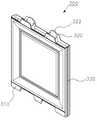
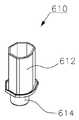
도 6은 본 발명의 일실시예에 따른 전면부의 모습을 도시한 사시도이고, 도 7은 본 발명의 일실시예에 따른 힌지핀의 모습을 도시한 사시도이며, 도 8은 본 발명의 일실시예에 따른 힌지홀더의 모습을 도시한 사시도이다.FIG. 6 is a perspective view illustrating a front portion according to an embodiment of the present invention, FIG. 7 is a perspective view illustrating a hinge pin according to an exemplary embodiment of the present invention, FIG. 8 is a cross- Fig. 3 is a perspective view showing a hinge holder according to a first embodiment of the present invention.
도 1a 및 1b에 도시된 바와 같이, 본 발명에 따른 전면부(500)는 수납함의 전면에서 바닥부(100)와 수직하여 배치되고, 사용자가 수납함을 개방 또는 폐쇄하고자 할 때 문의 역할을 한다.As shown in FIGS. 1A and 1B, the
상기 전면부(500)는 힌지핀(610)과 힌지홀더(600)를 매개로 바닥부(100)의 전면과 회동 가능하도록 연결되는데, 이는 힌지핀(610)이 힌지홀더(600)에 회전 가능하도록 연결되기 때문이다.The
구체적으로 도 6에 도시된 바와 같이, 상기 전면부(500)의 일측(도시된 실시예에서 좌측)에는 다각형의 단면을 가지며 상하방향으로 길게 형성된 다각형 통부(510)가 형성되고, 도 7에 도시된 것처럼 힌지핀(610)의 일측에 형성된 제1삽입핀(612)은 이러한 다각형 통부(510)에 삽입되어 고정된다.6, a
상기 힌지핀(610)의 타측에는 힌지홀더(600)에 형성된 중공(602)에 회전 가능하도록 삽입되는 원통형의 제2삽입핀(614)이 형성되고, 상기 힌지핀(610)이 힌지홀더(600) 상에서 회전함에 따라 전면부(500)는 회전된다.A
한편, 도 8에 도시된 바와 같이, 상기 힌지홀더(600)의 일측에는 삼각형의 후크형태(갈고리 형태)로 걸림부(604)가 형성되고, 이러한 걸림부(604)는 도 2b에 도시된 바닥부(100)의 전면에 형성된 바닥걸림홀(130) 또는 도 5b에 도시된 상면부(400)의 전면에 형성된 상면걸림홀(420)에 삽입된다.8, a latching
상기 바닥걸림홀(130) 또는 상면걸림홀(420)에 삽입된 걸림부(604)는 삽입과 동시에 걸림홀의 내부 공간에서 펼쳐서 걸리게 되고, 이에 따라 힌지홀더(600)는 바닥부(100)의 전면 또는 상면부(400)의 전면에 고정된다.The latching
이러한 상태에서 사용자는 전면부(500)와 힌지핀(610)이 결합된 조립물을 힌지홀더(600)에 삽입하여 조립을 마무리 짓고, 이에 따라 전면부는 수납함의 전면에 회동 가능하도록 조립된다.In this state, the user inserts the assembly with the
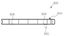
도 9는 본 발명의 일실시예에 따른 핸들의 모습을 도시한 사시도이고, 도 10a는 본 발명의 일실시예에 따른 제1커버패널을 위에서 바라본 모습을 도시한 사시도이며, 도 10b는 본 발명의 일실시예에 따른 제1커버패널을 아래에서 바라본 모습을 도시한 사시도이고, 도 10c는 본 발명의 일실시예에 따른 제1커버패널의 저면도이다.FIG. 9 is a perspective view illustrating a handle according to an embodiment of the present invention. FIG. 10A is a perspective view illustrating a first cover panel viewed from above, according to an embodiment of the present invention. FIG. 10C is a bottom view of a first cover panel according to an embodiment of the present invention. FIG. 10C is a bottom view of a first cover panel according to an embodiment of the present invention.
본 발명에 따른 조립식 수납함은, 상면 또는 하면 중 하나의 면은 막혀있고, 다른 하나의 면은 상기 전면부(500)의 상단 또는 하단이 삽입될 수 있도록 개방되어 있으며, 일측에 핸들(700)이 삽입될 수 있도록 핸들삽입구가 형성된 제1커버패널(800)을 더 포함하는 것이 바람직하다.In the assembled type storage box according to the present invention, one surface of the upper surface or the lower surface is closed, and the other surface is opened to allow the upper or lower end of the
상기 제1커버패널(800)은 전면부(500)의 상단 또는 하단에 삽입되어 전면부의 상단 또는 하단을 마감하는 역할을 함과 동시에 핸들(700)이 삽입될 수 있는 공간을 제공하는 역할을 한다.The
도 9 및 10b에 도시된 바와 같이, 상기 제1커버패널(800)의 일측면(전면)에는 원통 형상의 제1핸들삽입구(802)와 사각형의 제1핸들삽입홀(804)이 형성되고, 상기 핸들(700)에는 제1핸들삽입구(802)가 삽입될 수 있도록 제1결합부(710)가 형성되며 제1핸들삽입홀(804)에 삽입될 수 있도록 제2결합부(720)가 형성된다.9 and 10B, a cylindrical first
도 10a에 도시된 바와 같이, 상기 제1커버패널(800)의 타측면(후면)에는 십(十)자 형태의 제1핸들고리(806)가 형성되는데, 이러한 제1핸들고리(806)는 도 2b에 도시된 바닥부(100)의 전면에 형성된 바닥고리홀(132) 또는 도 5b에 도시된 상면부(400)의 전면에 형성된 상면고리홀(422)에 삽입되어 전면부가 뜻하지 않게 개방되는 것을 방지하는 역할을 한다.10A, a
한편, 도 6에 도시된 바와 같이, 상기 전면부(500)의 상단과 하단에는 다수의 커버홀(520)이 천공되고, 도 10c에 도시된 바와 같이, 상기 제1커버패널(800)의 내부에는 다수의 제1커버돌기(808)가 돌출된다.6, a plurality of cover holes 520 are formed in the upper and lower ends of the
사용자가 전면부(500)의 상단 또는 하단에서 제1커버패널(800)을 삽입하면 다수의 제1커버돌기(808)는 커버홀(520)로 삽입되고, 이에 따라 전면부(500)와 제1커버패널(800)은 견고하게 결합된다.When the user inserts the
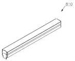
도 11a는 본 발명의 일실시예에 따른 제2커버패널을 위에서 바라본 모습을 도시한 사시도이고, 도 11b는 본 발명의 일실시예에 따른 제2커버패널을 아래에서 바라본 모습을 도시한 사시도이다.FIG. 11A is a perspective view illustrating a second cover panel according to an exemplary embodiment of the present invention, and FIG. 11B is a perspective view illustrating a second cover panel according to an exemplary embodiment of the present invention .
도 11a 및 11b에 도시된 바와 같이, 제2커버패널(810)은 상면 또는 하면 중 하나의 면이 막혀있고, 다른 하나의 면은 상기 전면부(500)의 상단 또는 하단이 삽입될 수 있도록 개방되어 있다.11A and 11B, the
상기 제2커버패널(810)은 전체적으로 제1커버패널(800)과 거의 유사한 형태를 취하나, 제1커버패널(800)과 달리 제1핸들삽입구(802)와 제1핸들고리(806)가 형성되지 않는다는 점에서 차이가 있다.The
즉, 상기 제2커버패널(810)은 전면부(500)의 상단 또는 하단에 삽입되어 전면부의 상단 또는 하단을 마감하는 역할을 할 뿐, 핸들(700)이 삽입될 수 있는 공간을 제공하는 역할은 하지 않는다.That is, the
도시되어 있지는 않지만, 상기 제2커버패널(810)의 내부에도 제1커버돌기(808)와 유사하게 다수의 커버돌기가 돌출되어 전면부(500)의 상단과 하단에 천공된 다수의 커버홀(520)에 삽입되며, 이에 따라 제2커버패널(810)과 전면부(500)는 결합된다.Although not shown, a plurality of cover projections protrude into the
도 1a에서 상기 제2커버패널(810)은 수납함의 상단과 하단에 각각 배치되어 있으나, 사용자는 이러한 제2커버패널을 제1커버패널로 대체하여 수납함의 상단과 하단에 핸들을 결합할 수도 있다는 것을 통상의 기술자는 이해할 수 있을 것이다.In FIG. 1A, the
도 12a는 본 발명의 일실시예에 따른 제3커버패널을 위에서 바라본 모습을 도시한 사시도이고, 도 12b는 본 발명의 일실시예에 따른 제3커버패널을 아래에서 바라본 모습을 도시한 사시도이다.12A is a perspective view illustrating a third cover panel according to an exemplary embodiment of the present invention, and FIG. 12B is a perspective view illustrating a third cover panel according to an exemplary embodiment of the present invention as viewed from below .
도 12a 및 12b에 도시된 바와 같이, 제3커버패널(820)은 전면부(500)의 상단 또는 하단이 삽입될 수 있도록 상면과 하면 모두 개방되어 있으며, 일측에 핸들(700)이 삽입될 수 있도록 핸들삽입구가 형성된다.12A and 12B, the
상기 제3커버패널(820)은 수납함의 하측에 배치된 전면부(500)와 그 상측에 배치된 전면부(500)의 사이에서 전면부의 사이를 서로 연결하는 역할을 함과 동시에 핸들(700)이 삽입될 수 있는 공간을 제공하는 역할을 한다.The
상기 제1커버패널(800)과 마찬가지로 제3커버패널(820)의 일측면(전면)에는 제3핸들삽입구(822)와 제3핸들삽입홀(824)이 형성되어 핸들(700)이 결합될 수 있도록 하고, 제3커버패널(820)의 타측면(후면)에는 십(十)자 형태의 제3핸들고리(826)가 형성되어 도 2b에 도시된 바닥부(100)의 전면에 형성된 바닥고리홀(132) 또는 도 5b에 도시된 상면부(400)의 전면에 형성된 상면고리홀(422)에 삽입된다.A third
또한, 상기 제3커버패널(820)의 내부에도 역시 전면부(500)의 상단과 하단에 형성된 다수의 커버홀(520)에 삽입될 수 있도록 다수의 제3커버돌기(828)가 돌출되며, 이에 따라 전면부(500)와 제3커버패널(820)은 견고하게 결합된다.A plurality of
도 1a에서 상기 제3커버패널(820)은 수납합의 상단과 하단 사이 즉, 중앙에 배치되어 전면부(500) 사이를 연결하고 있으며, 제3커버패널(820)에 결합된 핸들(700)을 이용해 사용자는 수납함을 개방할 수 있다.In FIG. 1A, the
도 13은 본 발명의 일실시예에 따른 제1발의 모습을 도시한 사시도이고, 도 14는 본 발명의 일실시예에 따른 제2발의 모습을 도시한 사시도이다.FIG. 13 is a perspective view illustrating a first foot according to an embodiment of the present invention, and FIG. 14 is a perspective view illustrating a second foot according to an embodiment of the present invention.
도 2b에 도시된 바와 같이, 상기 바닥부(100)의 하면 모퉁이에는 타원형 실린더 형상으로 다수의 제1관부(140)가 형성되는데, 사용자는 이러한 제1관부(140)에 제1발(900)을 삽입하여 수납함을 지지할 수 있다.2B, a plurality of
도 13에 도시된 바와 같이, 상기 제1발(900)은 제1관부(140)에 삽입될 수 있도록 한 쌍의 타원형 제1플러그(902)가 돌출되고, 전체적으로 육면체 형상이되 옆면이 사다리꼴의 형태로 형성된다.13, the
도 1a에 도시된 바와 같이, 사용자는 완성된 수납함 혹은 조립하기 전의 바닥부(100)에 다수의 제1발(900)을 결합하여 바닥부의 높이를 지상 면보다 높일 수 있다.As shown in FIG. 1A, a user can combine a plurality of
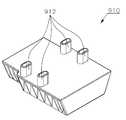
한편, 도 2b에 도시된 바와 같이, 상기 바닥부(100)의 하면 중앙부 전방과 후방에는 각각 다수의 제2관부(142)가 형성되며, 사용자는 제2관부(142)에 제2발(910)을 삽입하여 수납함을 더욱 견고하게 지지할 수 있다.2B, a plurality of
도 14에 도시된 바와 같이, 상기 제2발(910)은 제1발(900)과 전체적으로 유사하게 형성되나, 제2관부(142)에 삽입될 수 있도록 4개의 제2플러그(912)가 돌출되어 있으며, 바닥부(100)의 전방 또는 후방에 삽입될 수 있다.14, the
도 1a에서는 상기 제2발(910)이 바닥부(100)의 하면 중앙부 전방에만 결합되어 있으나, 사용자는 수납함의 용도 등을 고려하여 바닥부의 하면 중앙부 후방에도 역시 제2발을 결합할 수 있다.In FIG. 1A, the
전술한 것과 같이, 사용자는 바닥부(100)와 수직하여 후면부(200), 측면부(300) 및 전면부(500) 등을 조립한 후 상면부(400)를 조립하여 수납함을 완성하거나, 후면부, 측면부 및 전면부가 조립한 후 다시 바닥부(100)를 적층하여 다단으로 수납함을 완성하는 등 다양한 외형으로 본 발명에 따른 조립식 수납함을 완성할 수 있다.The user can assemble the
또한, 사용자는 바닥부(100)의 중앙부에 결합되는 측면부(300)를 삭제하거나 조립하여 수납함의 내부 공간 역시 자유롭게 구성할 수 있으며, 핸들(700) 역시 수납합의 상단 또는 중앙 등 원하는 위치에 배치할 수 있다.In addition, the user can freely configure the inner space of the storage box by deleting or assembling the
나아가, 사용자는 본 발명에 따른 조립식 수납함의 전면부(500)를 제거하여 문이 없는 형태로 활용할 수도 있으며, 상면부(400)를 제거하여 뚜껑이 없는 형태로 활용할 수도 있다.Further, the user may remove the
이와 같이, 본 발명에 따른 조립식 수납함은 사용자가 원하는 형태로 조립할 수 있으므로 공간 활용성이 극대화되고, 운반 시 부피를 최소화할 수 있으며, 별도의 조립 공구 없이 누구든지 원하는 장소에서 쉽게 해체 또는 재조립할 수 있는 효과가 있다.
As described above, since the assembled type storage box according to the present invention can be assembled in a form desired by the user, space utilization can be maximized, volume can be minimized during transportation, and anyone can easily disassemble or reassemble at a desired place without a separate assembling tool There is an effect.
이상에서 설명한 본 발명은 전술한 실시예 및 첨부된 도면에 의해 한정되는 것이 아니고, 본 발명의 기술적 사상을 벗어나지 않는 범위 내에서 여러 가지 치환, 변형 및 변경이 가능하다는 것이 본 발명이 속하는 기술분야에서 통상의 지식을 가진 자에게 있어 명백할 것이다.
It will be apparent to those skilled in the art that various modifications and variations can be made in the present invention without departing from the spirit or scope of the invention. Will be apparent to those of ordinary skill in the art.
100 : 바닥부102 : 바닥리브
110 : 돌출부110a : 돌출부의 경사면
112 : 돌출삽입부120 : 함몰부
120a : 함몰부의 경사면122 : 함몰삽입부
130 : 바닥걸림홀132 : 바닥고리홀
140 : 제1관부142 : 제2관부
200 : 후면부210 : 제1후면융기부
212 : 제1후면돌기220 : 제2후면융기부
222 : 제2후면돌기230 : 활주홈
300 : 측면부310 : 제1측면융기부
312 : 제1측면돌기320 : 제2측면융기부
322 : 제2측면돌기330 : 슬라이더
400 : 상면부402 : 상면리브
410 : 삽입홀420 : 상면걸림홀
422 : 상면고리홀500 : 전면부
510 : 다각형 통부520 : 커버홀
600 : 힌지홀더602 : 힌지홀더의 중공
604 : 걸림부610 : 힌지핀
612 : 제1삽입핀614 : 제2삽입핀
700 : 핸들710 : 제1결합부
720 : 제2결합부800 : 제1커버패널
802 : 제1핸들삽입구804 : 제1핸들삽입홀
806 : 제1핸들고리808 : 제1커버돌기
810 : 제2커버패널820 : 제3커버패널
822 : 제3핸들삽입구824 : 제3핸들삽입홀
826 : 제3핸들고리828 : 제3커버돌기
900 : 제1발902 : 제1플러그
910 : 제2발912 : 제2플러그100: bottom part 102: bottom rib
110: protruding portion 110a: inclined surface of the protruding portion
112: protrusion insertion portion 120: depression portion
120a: inclined surface of depression portion 122: depression insertion portion
130: bottom hole 132: bottom hole
140: first tube portion 142: second tube portion
200: rear portion 210: first rear ridge
212: first rear projection 220: second rear projection
222: second rear projection 230: slide groove
300: side portion 310: first side ridge
312: first side projections 320: second side ridges
322: second side projection 330: slider
400: upper surface portion 402: upper surface rib
410: insertion hole 420: upper surface locking hole
422: upper surface ring hole 500: front surface portion
510: polygonal barrel 520: cover hole
600: Hinge holder 602: Hollow holder hollow
604: Retaining part 610: Hinge pin
612: first insertion pin 614: second insertion pin
700: handle 710: first engaging portion
720: second coupling part 800: first cover panel
802: first handle insertion hole 804: first handle insertion hole
806: first handle ring 808: first cover projection
810: second cover panel 820: third cover panel
822: third handle insertion hole 824: third handle insertion hole
826: third handle ring 828: third cover projection
900: first leg 902: first plug
910: second foot 912: second plug
Claims (15)
Translated fromKorean상기 바닥부의 후면 모서리에 형성된 함몰부의 상면과 돌출부의 하면에 각각 삽입가능하도록 다수의 서로 이격된 제1후면융기부와 제2후면융기부가 형성되고, 상기 제1후면융기부와 제2후면융기부의 끝단에는 각각 함몰삽입부와 돌출삽입부에 삽입되는 제1후면돌기와 제2후면돌기가 돌출되는 후면부;
상기 바닥부의 측면 모서리 또는 중앙부에 형성된 함몰부의 상면과 돌출부의 하면에 각각 삽입가능하도록 다수의 서로 이격된 제1측면융기부와 제2측면융기부가 형성되고, 상기 제1측면융기부와 제2측면융기부의 끝단에는 각각 함몰삽입부와 돌출삽입부에 삽입되는 제1측면돌기와 제2측면돌기가 돌출되는 측면부;
모서리와 중앙부를 따라 상기 제2후면돌기 및 제2측면돌기가 삽입될 수 있도록 다수의 삽입홀이 천공되는 상면부; 및
상기 바닥부의 전면과 힌지핀 및 힌지홀더를 매개로 회동 가능하도록 연결되는 전면부; 를 포함하는 것을 특징으로 하는 조립식 수납함.
Shaped protrusions and '└┘' recesses are alternately formed along corners and a center portion, and a protrusion and a depression are formed at one side of the depression and the depression, respectively;
A plurality of first rear ridges and second rear ridges spaced apart from each other so as to be respectively insertable into the upper surface of the depression formed at the rear edge of the bottom portion and the lower surface of the protruding portion are formed and the first rear ridge portion and the second rear ridge portion A rear portion protruding from the rear end of the first rear protrusion and the second rear protrusion inserted into the recess insertion portion and the protrusion insertion portion, respectively;
A plurality of first side surface raised portions and a second side surface raised portions are formed so as to be respectively insertable into the upper surface of the depressed portion formed at the side edge or the central portion of the bottom portion and the lower surface of the projecting portion, And a side surface protruding from the tip of the ridge portion, the first side surface protrusion and the second side surface protrusion being inserted into the depression insertion portion and the protrusion insertion portion, respectively;
An upper surface portion in which a plurality of insertion holes are perforated so that the second rear protrusions and the second side surface protrusions can be inserted along corners and a central portion; And
A front portion rotatably connected to a front surface of the bottom portion via a hinge pin and a hinge holder; Wherein the first and second housings are formed of a resin.
상기 바닥부에 형성된 돌출부의 높이와 함몰부의 깊이는 동일하게 형성되며, 돌출부의 마주보는 양 측면과 함몰부의 마주보는 양 측면은 미리 정해진 각도로 경사면이 각각 형성되는 것을 특징으로 하는 조립식 수납함.
The method according to claim 1,
Wherein the height of the protrusion formed on the bottom portion is the same as the depth of the depressed portion, and both opposite side surfaces of the protrusion and the opposite side surfaces of the depression portion are formed with inclined surfaces at predetermined angles, respectively.
상기 바닥부의 하면에는 정육각형 형태로 돌출된 다수의 바닥리브가 형성되는 것을 특징으로 하는 조립식 수납함.
The method according to claim 1,
And a plurality of bottom ribs protruding in the form of a regular hexagon are formed on the bottom surface of the bottom portion.
상기 후면부에 형성된 제1후면돌기와 제2후면돌기는 후크 형태로 이루어져 각각 함몰삽입부와 돌출삽입부에 삽입과 동시에 걸려서 후면부의 유격을 제한하는 것을 특징으로 하는 조립식 수납함.
The method according to claim 1,
Wherein the first rear protrusion and the second rear protrusion formed on the rear portion are hook-shaped, and are engaged with the recessed insertion portion and the protrusion insertion portion at the same time, thereby limiting the clearance of the rear portion.
상기 후면부에 형성된 제1후면융기부의 폭은 함몰부의 폭과 동일하고, 제2후면융기부의 폭은 돌출부의 폭과 동일한 것을 특징으로 하는 조립식 수납함.
The method according to claim 1,
Wherein a width of the first rear ridge portion formed on the rear portion is equal to a width of the depressed portion and a width of the second rear ridge portion is equal to a width of the protrusion portion.
상기 측면부에 형성된 제1측면돌기와 제2측면돌기는 후크 형태로 이루어져 각각 함몰삽입부와 돌출삽입부에 삽입과 동시에 걸려서 측면부의 유격을 제한하는 것을 특징으로 하는 조립식 수납함.
The method according to claim 1,
Wherein the first side surface protrusions and the second side surface protrusions formed on the side surface portions are hook-shaped, and are engaged with the depression insertion portion and the protrusion insertion portion at the same time, thereby limiting the clearance of the side surface portion.
상기 측면부에 형성된 제1측면융기부의 폭은 함몰부의 폭과 동일하고, 제2측면융기부의 폭은 돌출부의 폭과 동일한 것을 특징으로 하는 조립식 수납함.
The method according to claim 1,
Wherein a width of the first side raised portion formed on the side portion is equal to a width of the depressed portion, and a width of the second side raised portion is equal to a width of the protruded portion.
상기 측면부의 일측면에는 상하방향으로 길게 슬라이더가 돌출 형성되고, 상기 후면부에는 슬라이더가 활주할 수 있도록 활주홈이 상하방향으로 길게 형성되어 측면부와 후면부가 상호 연결되는 것을 특징으로 하는 조립식 수납함.
The method according to claim 1,
A slider protruding in a vertical direction is formed on one side surface of the side portion, and a slide groove is formed to be long in a vertical direction so that the slider can be slid on the rear portion, so that the side portion and the rear portion are mutually connected.
상기 상면부의 하면에는 정육각형 형태로 돌출된 다수의 상면리브가 형성되는 것을 특징으로 하는 조립식 수납함.
The method according to claim 1,
And a plurality of upper surface ribs protruding in the form of a regular hexagon are formed on the lower surface of the upper surface portion.
상기 전면부의 일측에 형성된 다각형 통부에 삽입될 수 있도록 다각형 단면을 가지는 제1삽입핀; 및
상기 힌지홀더에 회전 가능하도록 삽입되는 원통형의 제2삽입핀; 을 포함하는 것을 특징으로 하는 조립식 수납함.
The hinge pin according to claim 1,
A first insert pin having a polygonal cross-section so as to be inserted into a polygonal barrel formed on one side of the front portion; And
A cylindrical second insertion pin rotatably inserted into the hinge holder; Wherein the first and second housings are formed of a metal.
상면 또는 하면 중 하나의 면은 막혀있고, 다른 하나의 면은 상기 전면부의 상단 또는 하단이 삽입될 수 있도록 개방되어 있으며, 일측에 핸들이 삽입될 수 있도록 핸들삽입구가 형성된 제1커버패널; 을 더 포함하는 것을 특징으로 하는 조립식 수납함.
The method according to claim 1,
A first cover panel having a top surface or a bottom surface clogged and the other surface open to allow the top or bottom of the front surface to be inserted and having a handle insertion port for insertion of the handle into one side; Further comprising a plurality of openings formed in the housing.
상면 또는 하면 중 하나의 면은 막혀있고, 다른 하나의 면은 상기 전면부의 상단 또는 하단이 삽입될 수 있도록 개방되어 있는 제2커버패널; 을 더 포함하는 것을 특징으로 하는 조립식 수납함.
The method according to claim 1,
A second cover panel having one surface of the upper surface or the lower surface blocked and the other surface opened to allow insertion of the upper or lower end of the front surface portion; Further comprising a plurality of openings formed in the housing.
상기 전면부의 상단 또는 하단이 삽입될 수 있도록 상면과 하면 모두 개방되어 있으며, 일측에 핸들이 삽입될 수 있도록 핸들삽입구가 형성된 제3커버패널; 을 더 포함하는 것을 특징으로 하는 조립식 수납함.
The method according to claim 1,
A third cover panel having both a top surface and a bottom surface so that an upper end or a lower end of the front portion can be inserted and having a handle inserting hole into which a handle can be inserted; Further comprising a plurality of openings formed in the housing.
상기 바닥부의 하면 모퉁이에 형성된 다수의 제1관부; 및
상기 제1관부에 삽입될 수 있도록 한 쌍의 제1플러그가 돌출된 제1발; 을 더 포함하는 것을 특징으로 하는 조립식 수납함.
The method according to claim 1,
A plurality of first tube portions formed on a bottom corner of the bottom portion; And
A first foot having a pair of first plugs protruded to be inserted into the first tube portion; Further comprising a plurality of openings formed in the housing.
상기 바닥부의 하면 중앙부에 형성된 다수의 제2관부; 및
상기 제2관부에 삽입될 수 있도록 4개의 제2플러그가 돌출된 제2발; 을 더 포함하는 것을 특징으로 하는 조립식 수납함.The method according to claim 1,
A plurality of second tube portions formed at the center of the bottom surface of the bottom portion; And
A second foot having four second plugs protruded to be inserted into the second tube portion; Further comprising a plurality of openings formed in the housing.
Priority Applications (1)
| Application Number | Priority Date | Filing Date | Title |
|---|---|---|---|
| KR1020150157875AKR101622772B1 (en) | 2015-11-11 | 2015-11-11 | Self-assembly drawer |
Applications Claiming Priority (1)
| Application Number | Priority Date | Filing Date | Title |
|---|---|---|---|
| KR1020150157875AKR101622772B1 (en) | 2015-11-11 | 2015-11-11 | Self-assembly drawer |
Publications (1)
| Publication Number | Publication Date |
|---|---|
| KR101622772B1true KR101622772B1 (en) | 2016-05-20 |
Family
ID=56103932
Family Applications (1)
| Application Number | Title | Priority Date | Filing Date |
|---|---|---|---|
| KR1020150157875AExpired - Fee RelatedKR101622772B1 (en) | 2015-11-11 | 2015-11-11 | Self-assembly drawer |
Country Status (1)
| Country | Link |
|---|---|
| KR (1) | KR101622772B1 (en) |
Cited By (2)
| Publication number | Priority date | Publication date | Assignee | Title |
|---|---|---|---|---|
| KR101958592B1 (en)* | 2018-03-21 | 2019-07-04 | 정소진 | Fabricable furniture |
| KR200492227Y1 (en) | 2019-08-27 | 2020-09-01 | 주식회사 한화고분자 | Self-Assembly Cabinets |
Citations (2)
| Publication number | Priority date | Publication date | Assignee | Title |
|---|---|---|---|---|
| JP3192100U (en) | 2012-09-20 | 2014-07-31 | ▲呉▼峰 | Storage such as plastic lockers that can be quickly disassembled and assembled |
| JP3199898U (en) | 2015-07-03 | 2015-09-17 | 株式会社伸和 | Assembly shelf |
- 2015
- 2015-11-11KRKR1020150157875Apatent/KR101622772B1/ennot_activeExpired - Fee Related
Patent Citations (2)
| Publication number | Priority date | Publication date | Assignee | Title |
|---|---|---|---|---|
| JP3192100U (en) | 2012-09-20 | 2014-07-31 | ▲呉▼峰 | Storage such as plastic lockers that can be quickly disassembled and assembled |
| JP3199898U (en) | 2015-07-03 | 2015-09-17 | 株式会社伸和 | Assembly shelf |
Cited By (2)
| Publication number | Priority date | Publication date | Assignee | Title |
|---|---|---|---|---|
| KR101958592B1 (en)* | 2018-03-21 | 2019-07-04 | 정소진 | Fabricable furniture |
| KR200492227Y1 (en) | 2019-08-27 | 2020-09-01 | 주식회사 한화고분자 | Self-Assembly Cabinets |
Similar Documents
| Publication | Publication Date | Title |
|---|---|---|
| US20200039056A1 (en) | Inserts for an Assortment Box | |
| US20100006467A1 (en) | Storage container | |
| US9398806B2 (en) | Snap together safety storage cabinet | |
| JP2020045172A (en) | Box, combination structure of stacked boxes, and method of mechanically gripping stacked boxes | |
| KR101622772B1 (en) | Self-assembly drawer | |
| KR101325664B1 (en) | Side open type container | |
| KR101963744B1 (en) | Multi-purpose storage box | |
| US20130068762A1 (en) | Assembled Box | |
| KR200415144Y1 (en) | Slim box | |
| KR100823656B1 (en) | Multi-stage stackable storage box | |
| CN101304924B (en) | Portable Stackable Plastic Multi-Purpose Container | |
| KR200481094Y1 (en) | Drawer having multiple directions | |
| JP5909072B2 (en) | Tray and its storage shelf | |
| KR101196092B1 (en) | Folding storage box | |
| KR200334987Y1 (en) | A drawer type custody box | |
| KR200344002Y1 (en) | Multi-purpose box | |
| JP6308973B2 (en) | Storage | |
| KR20090082055A (en) | Multi-purpose prefabricated storage box | |
| TWM565681U (en) | Logistics box | |
| KR101648679B1 (en) | A containment tray | |
| KR101859816B1 (en) | BOX for a drawer | |
| JP3161928U (en) | Storage case | |
| CN204987639U (en) | But refrigeration utensil and box of pulling out that has oscillating wall spare | |
| JPH07148040A (en) | Built-up type drawing box | |
| KR200443105Y1 (en) | Pallet |
Legal Events
| Date | Code | Title | Description |
|---|---|---|---|
| PA0109 | Patent application | St.27 status event code:A-0-1-A10-A12-nap-PA0109 | |
| PA0201 | Request for examination | St.27 status event code:A-1-2-D10-D11-exm-PA0201 | |
| PA0302 | Request for accelerated examination | St.27 status event code:A-1-2-D10-D17-exm-PA0302 St.27 status event code:A-1-2-D10-D16-exm-PA0302 | |
| P11-X000 | Amendment of application requested | St.27 status event code:A-2-2-P10-P11-nap-X000 | |
| P13-X000 | Application amended | St.27 status event code:A-2-2-P10-P13-nap-X000 | |
| D13-X000 | Search requested | St.27 status event code:A-1-2-D10-D13-srh-X000 | |
| D14-X000 | Search report completed | St.27 status event code:A-1-2-D10-D14-srh-X000 | |
| E701 | Decision to grant or registration of patent right | ||
| PE0701 | Decision of registration | St.27 status event code:A-1-2-D10-D22-exm-PE0701 | |
| GRNT | Written decision to grant | ||
| PR0701 | Registration of establishment | St.27 status event code:A-2-4-F10-F11-exm-PR0701 | |
| PR1002 | Payment of registration fee | St.27 status event code:A-2-2-U10-U11-oth-PR1002 Fee payment year number:1 | |
| PG1601 | Publication of registration | St.27 status event code:A-4-4-Q10-Q13-nap-PG1601 | |
| PJ0204 | Invalidation trial for patent | St.27 status event code:A-5-5-V10-V11-apl-PJ0204 | |
| J301 | Trial decision | Free format text:TRIAL NUMBER: 2016100002082; TRIAL DECISION FOR INVALIDATION REQUESTED 20160715 Effective date:20170829 | |
| PJ1301 | Trial decision | St.27 status event code:A-5-5-V10-V15-crt-PJ1301 Decision date:20170829 Appeal event data comment text:Appeal Kind Category : Invalidation, Appeal Ground Text : 1622772 Appeal request date:20160715 Appellate body name:Patent Examination Board Decision authority category:Office appeal board Decision identifier:2016100002082 | |
| PJ2001 | Appeal | St.27 status event code:A-5-5-V10-V12-crt-PJ2001 | |
| P22-X000 | Classification modified | St.27 status event code:A-4-4-P10-P22-nap-X000 | |
| J302 | Written judgement (patent court) | Free format text:TRIAL NUMBER: 2017200007487; JUDGMENT (PATENT COURT) FOR INVALIDATION REQUESTED 20171030 Effective date:20180907 | |
| PJ1302 | Judgment (patent court) | St.27 status event code:A-5-5-V10-V15-crt-PJ1302 Decision date:20180907 Decision identifier:2017200007487 Decision authority category:National patent court Appeal event data comment text:Appeal Kind Category : Invalidation, Appeal Ground Text : 20162082 (1622772) Appeal request date:20171030 Appellate body name:Patent Court | |
| PR1001 | Payment of annual fee | St.27 status event code:A-4-4-U10-U11-oth-PR1001 Fee payment year number:4 | |
| PR1001 | Payment of annual fee | St.27 status event code:A-4-4-U10-U11-oth-PR1001 Fee payment year number:5 | |
| S17-X000 | Non-exclusive voluntary license recorded | St.27 status event code:A-4-4-S10-S17-lic-X000 | |
| PC1903 | Unpaid annual fee | St.27 status event code:A-4-4-U10-U13-oth-PC1903 Not in force date:20210514 Payment event data comment text:Termination Category : DEFAULT_OF_REGISTRATION_FEE | |
| PC1903 | Unpaid annual fee | St.27 status event code:N-4-6-H10-H13-oth-PC1903 Ip right cessation event data comment text:Termination Category : DEFAULT_OF_REGISTRATION_FEE Not in force date:20210514 |