KR101622603B1 - Portable terminal - Google Patents
Portable terminalDownload PDFInfo
- Publication number
- KR101622603B1 KR101622603B1KR1020090034365AKR20090034365AKR101622603B1KR 101622603 B1KR101622603 B1KR 101622603B1KR 1020090034365 AKR1020090034365 AKR 1020090034365AKR 20090034365 AKR20090034365 AKR 20090034365AKR 101622603 B1KR101622603 B1KR 101622603B1
- Authority
- KR
- South Korea
- Prior art keywords
- conductor
- portable terminal
- metal dome
- dome
- contact surface
- Prior art date
- Legal status (The legal status is an assumption and is not a legal conclusion. Google has not performed a legal analysis and makes no representation as to the accuracy of the status listed.)
- Expired - Fee Related
Links
Images


Classifications
- H—ELECTRICITY
- H01—ELECTRIC ELEMENTS
- H01H—ELECTRIC SWITCHES; RELAYS; SELECTORS; EMERGENCY PROTECTIVE DEVICES
- H01H13/00—Switches having rectilinearly-movable operating part or parts adapted for pushing or pulling in one direction only, e.g. push-button switch
- H01H13/02—Details
- H01H13/26—Snap-action arrangements depending upon deformation of elastic members
- H01H13/48—Snap-action arrangements depending upon deformation of elastic members using buckling of disc springs
- H—ELECTRICITY
- H01—ELECTRIC ELEMENTS
- H01H—ELECTRIC SWITCHES; RELAYS; SELECTORS; EMERGENCY PROTECTIVE DEVICES
- H01H13/00—Switches having rectilinearly-movable operating part or parts adapted for pushing or pulling in one direction only, e.g. push-button switch
- H01H13/70—Switches having rectilinearly-movable operating part or parts adapted for pushing or pulling in one direction only, e.g. push-button switch having a plurality of operating members associated with different sets of contacts, e.g. keyboard
- H01H13/702—Switches having rectilinearly-movable operating part or parts adapted for pushing or pulling in one direction only, e.g. push-button switch having a plurality of operating members associated with different sets of contacts, e.g. keyboard with contacts carried by or formed from layers in a multilayer structure, e.g. membrane switches
- H—ELECTRICITY
- H04—ELECTRIC COMMUNICATION TECHNIQUE
- H04M—TELEPHONIC COMMUNICATION
- H04M1/00—Substation equipment, e.g. for use by subscribers
- H04M1/02—Constructional features of telephone sets
- H04M1/23—Construction or mounting of dials or of equivalent devices; Means for facilitating the use thereof
Landscapes
- Engineering & Computer Science (AREA)
- Signal Processing (AREA)
- Telephone Set Structure (AREA)
- Push-Button Switches (AREA)
Abstract
Translated fromKoreanDescription
Translated fromKorean본 발명은 향상된 클릭감을 갖는 돔 스위치가 적용된 휴대 단말기에 관한 것이다.The present invention relates to a mobile terminal to which a dome switch having an improved click feeling is applied.
휴대 단말기는 휴대가 가능하면서 음성 및 영상 통화 기능, 정보를 입·출력하는 기능 및 데이터를 저장할 수 있는 기능 등을 하나 이상 갖춘 휴대용 기기이다.A portable terminal is a portable device that is portable and has one or more functions such as voice and video call function, information input / output function, and data storing function.
그리고 휴대 단말기는 기능이 다양화됨에 따라 예를 들어 사진이나 동영상의 촬영, 음악이나 동영상 파일의 재생, 게임, 방송의 수신 등의 복잡한 기능들을 갖추고 있으며, 종합적인 멀티미디어 기기(Multimedia player) 형태로 구현되고 있다.As the functions of the portable terminal are diversified, for example, the portable terminal has complicated functions such as photographing and photographing of a moving picture, reproduction of music or video file, reception of a game and broadcasting, and is implemented as a multimedia device .
이러한 멀티 미디어 기기에는 복잡한 기능을 구현하기 위해 하드웨어 또는 소프트웨어의 면에서 새로운 다양한 시도들이 적용되고 있다. 일 예로 사용자가 쉽고 편리하게 기능을 검색하거나 선택하기 위한 유저 인터페이스(User Interface) 환경이 제공되고 있다.In order to implement complex functions in multimedia devices, various new attempts have been made in terms of hardware or software. For example, a user interface environment is provided for a user to easily and conveniently search for or select a function.
휴대 단말기는 사용자의 조작에 의해 정보를 입력하는 입력 장치들을 가지 며, 이들 입력 장치들은 사용자의 푸시 또는 터치 조작에 의해 명령 또는 정보를 입력받을 수 있는 돔 스위치 또는 터치 패드로 구현되거나, 키를 회전시키는 휠 또는 조그 방식이나 조이스틱과 같이 조작하는 방식 등으로 구현된다.The portable terminal has input devices for inputting information by a user's operation, and these input devices may be embodied as a dome switch or a touch pad capable of receiving commands or information by a push or touch operation of a user, Or a jog system or a joystick system.
이와 같은 다양한 방식들 중 돔 스위치는 단순하고 신뢰성 있는 구조를 가지고, 사용자가 클릭감을 느낄 수 있는 장점을 가지기 때문에 휴대 단말기에 가장 일반적으로 적용되고 있고 있다.Of these various methods, the dome switch has a simple and reliable structure and is most commonly applied to a mobile terminal because it has the advantage that the user can feel the click feeling.
본 발명은 메탈돔의 변형시 메탈돔의 스트로크를 증가시켜 클릭감을 향상시킬 수 있는 돔 스위치의 구조를 제공하기 위한 것이다.The present invention provides a structure of a dome switch capable of increasing a stroke of a metal dome and improving a click feeling when the metal dome is deformed.
상기한 과제를 실현하기 위한 본 발명은 기판의 일면에 형성되며, 접촉면을 구비하는 제1도전체와; 상기 제1도전체의 외곽에 형성되며, 지지면을 구비하는 제2도전체; 및 상기 지지면에 의해 지지되며, 키의 누름 동작에 의해 변형되어 상기 접촉면에 접촉되는 메탈 돔을 포함하고, 상기 접촉면은 상기 메탈 돔의 변형 스트로크를 증가시키도록 상기 지지면보다 낮은 위치에 형성되는 것을 특징으로 하는 휴대 단말기를 개시한다.According to an aspect of the present invention, there is provided a semiconductor device comprising: a first conductor formed on one surface of a substrate and having a contact surface; A second conductor formed on an outer periphery of the first conductor and having a support surface; And a metal dome supported by the support surface and deformed by a pressing operation of the key to contact the contact surface, wherein the contact surface is formed at a lower position than the support surface to increase the deformation stroke of the metal dome And a portable terminal.
본 발명의 일 예로서, 상기 제1도전체는 상기 기판의 주면보다 낮은 위치에 형성될 수 있으며, 이러한 구조의 일 예로서 제1도전체가 기판에 형성된 리세스부에 위치하는 구조를 들 수 있다.As an example of the present invention, the first conductor may be formed at a position lower than the main surface of the substrate, and a structure in which the first conductor is located in a recess portion formed in the substrate is an example of such a structure .
본 발명의 일 예로서, 상기 제1도전체의 접촉면과 제2도전체의 지지면은 상기 기판의 주면보다 높은 위치에 형성될 수 있으며, 이러한 구조로서 제2도전체가 제1도전체보다 두꺼운 두께를 갖거나 제2도전체의 지지점 높이를 증가시키는 지지부재가 적용된 구조를 들 수 있다.In one embodiment of the present invention, the contact surface of the first conductor and the support surface of the second conductor may be formed at a position higher than the main surface of the substrate. In this structure, the second conductor may be thicker than the first conductor Or a supporting member for increasing the height of the supporting point of the second conductor is applied.
상기와 같은 구조의 본 발명은 제1도전체의 접촉면을 제2도전체의 지지면보 다 낮은 위치에 형성시켜 메탈 돔의 변형시 스트로크를 증가시킴으로써, 클릭감이 향상된 돔 스위치를 제공하는 이점이 있다.The present invention having such a structure is advantageous in providing a dome switch having an improved click feeling by forming a contact surface of the first conductor at a position lower than the supporting surface of the second conductor to increase the stroke at the time of deformation of the metal dome .
또한, 본 발명은 간단한 구조를 통해 메탈 돔의 스트로크가 증가된 구조를 구현한다.Further, the present invention realizes a structure in which the stroke of the metal dome is increased through a simple structure.
이하, 본 발명에 관련된 휴대 단말기에 대하여 도면을 참조하여 보다 상세하게 설명한다.Hereinafter, a portable terminal according to the present invention will be described in detail with reference to the drawings.
도 1은 본 발명에 관련된 휴대 단말기(100)의 일 예를 전면에서 바라본 사시도이다.1 is a perspective view of an example of a
본 발명의 휴대 단말기는 제1바디(110)와, 제1바디(110)에 적어도 일 방향을 따라 슬라이딩 가능하게 구성된 제2바디(120)를 포함한다. 본 실시예에서는 슬라이드 타입의 휴대 단말기를 예시하고 있으나, 본 발명은 이에 한정되지 않고 바 타입, 폴더 타입, 스위블 타입, 스윙 타입 등 다양한 형태의 휴대 단말기에 적용 가능하다.The portable terminal of the present invention includes a
제1바디(110)가 제2바디(120)와 중첩되게 배치된 상태를 닫힌 상태(closed configuration)라 칭할 수 있으며, 본 도면에 도시된 바와 같이 제1바디(110)가 제2바디(120)의 적어도 일 부분을 노출한 상태를 열린 상태(open configuration)라 칭할 수 있다.The
휴대 단말기는 닫힌 상태에서 주로 대기 모드로 작동하지만 사용자의 조작에 의해 대기 모드가 해제되기도 한다. 그리고, 휴대 단말기(100)는 열린 상태에서 주 로 통화 모드 등으로 작동하지만 사용자의 조작 또는 소정 시간의 경과에 의해 대기 모드로 전환되기도 한다.The mobile terminal operates mainly in the standby mode in the closed state, but the standby mode is also released by the user's operation. In addition, the
제1바디(110)의 외관을 이루는 케이스(케이싱, 하우징, 커버 등)는 프론트 케이스(111)와 리어 케이스(112)에 의해 형성된다. 프론트 케이스(110)와 리어 케이스(120)에 의해 형성된 공간에는 각종 전자부품들이 내장된다.The casing (housing, housing, cover, etc.) constituting the outer appearance of the
프론트 케이스(111)와 리어 케이스(112) 사이에는 적어도 하나의 중간 케이스들이 추가로 배치될 수도 있다.At least one intermediate case may be additionally disposed between the
케이스들은 합성수지를 사출하여 형성되거나 금속 재질, 예를 들어 스테인레스 스틸(STS) 또는 티타늄(Ti) 등과 같은 금속 재질을 갖도록 형성될 수도 있다.The cases may be formed by injection molding a synthetic resin, or may be formed to have a metal material such as stainless steel (STS) or titanium (Ti) or the like.
제1바디(110), 구체적으로 프론트 케이스(111)에는 디스플레이부(113), 제1음향출력부(114), 제1영상입력부(115) 또는 제1조작부(116)가 배치될 수 있다.The
디스플레이부(113)는 정보를 시각적으로 표현하는 LCD(liquid crystal display) 모듈, OLED(Organic Light Emitting Diodes) 모듈 등을 포함하고, 디스플레이부(113)는 터치 스크린을 더 포함하여 사용자의 터치에 의한 정보의 입력 또한 가능하게 할 수도 있다.The
제1음향출력부(114)는 리시버(Receiver) 또는 스피커(speaker)의 형태로 구현될 수 있으며, 제1영상입력부(115)는 사용자 등에 대한 이미지 또는 동영상을 촬영하기 위한 카메라 모듈과 같은 형태로 구현될 수 있다.The first
제1조작부(116)는 본 발명의 일예에 관련된 휴대 단말기의 동작을 제어하기 위한 명령을 입력 받는다.The
제1바디(110)와 마찬가지로, 프론트 케이스(121)와 리어 케이스(122)가 제2 바디(120)의 케이스를 형성할 수 있다. 제2바디(120), 구체적으로 프론트 케이스(121)의 전면(front face)에는 제2조작부(123)가 배치될 수 있다.The
프론트 케이스(121) 또는 리어 케이스(122) 중 적어도 하나에는 제3조작부(124), 음향 입력부(125), 인터페이스(126)가 배치될 수 있다.At least one of the
제1 내지 제3조작부(116,123,124)는 조작부(manipulating portion)라 통칭될 수 있으며, 사용자가 촉각적인 느낌을 가면서 조작하게 되는 방식(tactile manner)이라면 어떤 방식이든 채용될 수 있다.The first to third operating
예를 들어, 조작부는 사용자의 푸시 또는 터치 조작에 의해 명령 또는 정보를 입력받을 수 있는 돔 스위치 또는 터치 스크린, 터치 패드로 구현되거나, 키를 회전시키는 휠 또는 조그 방식이나 조이스틱과 같이 조작하는 방식 등으로도 구현될 수 있다.For example, the operation unit may be implemented by a dome switch or a touch screen, a touch pad, or a wheel, a jog type, a joystick, or the like, As shown in FIG.
기능적인 면에서, 제1조작부(116)는 시작, 종료, 스크롤 등과 같은 명령을 입력하기 위한 것이고, 제2조작부(123)는 숫자 또는 문자, 심볼(symbol) 등을 입력하기 위한 것이다. 또한, 제3조작부(124)는 제1영상입력부(15)의 활성화 등과 같은 특수한 기능을 수행하는 핫 키(hot-key)로서 작동할 수 있다.In terms of functions, the
음향입력부(125)는 사용자의 음성, 기타 소리 등을 입력 받기 위해, 예를 들어 마이크로폰(Microphone)과 같은 형태로 구현될 수 있다.The
인터페이스(126)는 본 발명과 관련된 휴대 단말기가 외부 기기와 데이터 교환 등을 할 수 있게 하는 통로가 된다. 예를 들어, 상기 인터페이스(126)는 유선 또는 무선으로, 이어폰과 연결하기 위한 접속단자, 근거리 통신을 위한 포트{예를 들어 적외선 포트(IrDA port), 블루투스 포트(Bluetooth port), 무선 랜 포트(wireless Lan port)등}, 또는 상기 휴대 단말기에 전원을 공급하기 위한 전원공급 단자들 중 적어도 하나일 수 있다.The
인터페이스(126)는 SIM(subscriber identification module) 또는 UIM(user identity module), 정보 저장을 위한 메모리 카드 등의 외장형 카드를 수용하는 카드 소켓일 수도 있다.The
리어 케이스(122) 측에는 상기 휴대 단말기에 전원을 공급하기 위한 전원공급부(127)가 장착된다. 전원공급부(127)는, 예를 들어 충전 가능한 배터리로서 충전 등을 위하여 착탈 가능하게 결합될 수 있다.A
도 2는 도 1의 휴대 단말기의 후면 사시도이다.2 is a rear perspective view of the portable terminal of FIG.
도 2를 참조하면, 제2바디(120)의 리어 케이스(122)의 후면에는 제2영상입력부(128)가 추가로 장착될 수 있다. 상기 제2영상입력부(128)는 제1영상입력부(15, 도 1 참조)와 실질적으로 반대되는 촬영 방향을 가지며, 제1영상입력부(115)와 서로 다른 화소를 가지는 카메라일 수 있다.Referring to FIG. 2, a second image input unit 128 may be additionally mounted on the rear surface of the
예를 들어, 제1영상입력부(115)는 화상 통화 등의 경우에 사용자의 얼굴을 촬영하여 상대방에 전송함에 무리가 없도록 저화소를 가지며, 제2영상입력부(128)는 일반적인 피사체를 촬영하고 바로 전송하지는 않는 경우가 많기에 고화소를 가지는 것이 바람직하다.For example, the first
제2영상입력부(128)에 인접하게는 플래쉬(129)와 거울부(130)가 추가로 배치 된다. 플래쉬(129)는 제2영상입력부(128)로 피사체를 촬영하는 경우에 상기 피사체를 향해 빛을 비추게 된다. 거울부(130)는 사용자가 제2영상입력부(128)를 이용하여 자신을 촬영(셀프 촬영)하고자 하는 경우에, 사용자 자신의 얼굴 등을 비춰볼 수 있게 한다.A flash 129 and a mirror 130 are further disposed adjacent to the second image input unit 128. The flash 129 illuminates the subject when the subject is photographed by the second image input unit 128. The mirror unit 130 allows the user to illuminate the user's own face or the like when the user intends to take a picture of himself / herself (self-photographing) using the second image input unit 128.
리어 케이스(122)에는 제2음향출력부(131)가 추가로 배치될 수도 있다.And the second sound output unit 131 may be further disposed in the
제2음향출력부(131)는 제1음향출력부(114, 도 1 참조)와 함께 스테레오 기능을 구현할 수 있으며, 스피커폰 모드로 통화를 위하여 사용될 수도 있다.The second sound output unit 131 may implement a stereo function together with the first sound output unit 114 (see FIG. 1), and may be used for talking in a speakerphone mode.
또한, 리어 케이스(122)의 일 측에는 통화 등을 위한 안테나 외에 방송신호 수신용 안테나(132)가 배치될 수 있다. 안테나(132)는 제2바디(120)에서 인출 가능하게 설치될 수 있다.Further, on one side of the
제1바디(110)의 리어 케이스(112) 측에는 제1바디(110)와 제2바디(120)를 슬라이딩 가능하게 결합하는 슬라이드 모듈(133)의 일 부분이 배치된다.A part of the slide module 133 which slidably couples the
슬라이드 모듈(133)의 다른 부분은 제2바디(120)의 프론트 케이스(121) 측에 배치되어, 본 도면에서와 같이 외부로 드러나지 않는 형태일 수 있다.The other part of the slide module 133 may be disposed on the
이상에서는 제2영상입력부(128) 등이 제2바디(120)에 배치되는 것으로 설명하였으나, 반드시 그에 제한되는 것은 아니다. 예를 들어, 제2영상입력부(128) 등과 같이 리어 케이스(122)에 배치되는 것으로 설명한 구성들(128 내지 132) 중 적어도 하나 이상이 제1바디(110), 주로는 리어 케이스(112)에 장착되는 것도 가능하다. 그러한 경우라면, 닫힌 상태에서 리어 케이스(112)에 배치되는 구성(들)이 제2바디(120)에 의해 보호되는 이점이 있다. 나아가, 제2영상입력부(128)가 별도로 구 비되지 않더라도, 제1영상입력부(115)가 회전 가능하게 형성되어 제2영상입력부(128)의 촬영 방향까지 촬영이 가능하도록 구성될 수도 있다.In the above description, the second image input unit 128 and the like are disposed in the
도 3은 본 발명의 일실시예와 관련된 휴대 단말기의 분해 사시도이고, 도 4는 도 3의 Ⅳ-Ⅳ 라인을 따르는 휴대 단말기의 단면도이다.FIG. 3 is an exploded perspective view of a portable terminal according to an embodiment of the present invention, and FIG. 4 is a sectional view of the portable terminal according to line IV-IV of FIG.
본 발명과 관련하여 제2조작부(123)는 누름 조작 가능한 복수의 키버튼(123a)들로서 구현된다. 본 실시예는 별개로 형성된 키버튼(123a)들이 제2바디(120)에 장착되는 것을 예시하고 있으나, 제2조작부(123)는 키버튼(123a)들이 일체로 형성되는 '키패드'의 형태로도 구현 가능하다.The
프론트 케이스(121)와 리어 케이스(122)의 사이에는 휴대 단말기의 동작을 위한 전자 부품들이 실장된 인쇄회로기판(136)이 장착된다. 본 실시예에서는 인쇄회로기판(136)으로서 리지드 기판(rigid PCB)을 예시하고 있으나, 연성회로기판(FPCB)이 사용되는 것도 가능하다.Between the
인쇄회로기판(136)에는 키버튼(123a)의 누름 동작에 따라 신호를 발생시키기 위한 돔 스위치(140)들이 장착된다. 키버튼(123a)의 배면에는 돔 스위치(140)들을 푸시하기 위한 푸시돌기(123b)들이 형성된다. 키버튼(123a)의 누름 동작시 푸시돌기(123b)들이 돔 스위치(140)들을 가압하게 되며, 돔 스위치(140)가 일정량 이상 변형(즉, 누름 동작)됨에 따라 입력 신호가 발생하게 된다.The printed
인쇄회로기판(136)의 돔 스위치(140)들 사이에는 키버튼(150)들을 조명하기 위한 조명 유닛(138)이 장착된다. 조명 유닛(138)은 키버튼(150)에 표시된 숫자, 문자, 기호 등을 조명하기 위한 것이다. 조명 유닛(138)은 전력의 손실을 줄이고 제조 단가를 줄일 수 있도록 발광 다이오드(LED)가 사용될 수 있다.Between the dome switches 140 of the printed
돔 스위치(140)의 메탈 돔(143, 도 7 참조)은 일정 면적을 갖는 접착 테입에 의해 인쇄회로기판(136)에 부착될 수 있으며, 접착 테입에는 조명 유닛(138)에서 나온 빛을 안내하는 도광 필름이 구비될 수 있다.The
도 5a 및 5b는 일반적인 형태의 돔 스위치의 구조 및 작동 상태를 나타내는 단면도들이다. 그리고, 도 6은 메탈 돔의 변형에 따라 메탈 돔에 작용하는 힘의 크기를 나타낸 그래프이다.5A and 5B are cross-sectional views showing the structure and operating state of a dome switch in a general form. 6 is a graph showing the magnitude of the force acting on the metal dome according to the deformation of the metal dome.
도 5a 및 5b를 참조하면, 돔 스위치(10)는 기판(11) 상에 패턴화된 제1 및 제2도전체(12,13)와, 누름 동작에 의해 제1 및 제2도전체(12,13)를 전기적으로 연결하는 메탈 돔(14)을 포함한다.5A and 5B, the
제1도전체(12)는 메탈 돔(14)의 중앙 부위에 대응되는 위치에 형성된다. 그리고, 제2도전체(13)는 제1도전체(12)의 둘레에 감싸는 링 또는 밴드 형태로 형성되며, 메탈 돔(14)는 제2도전체(13)에 의해 지지된다.The
도 5a의 상태에서 메탈 돔(14)이 가압되면 메탈 돔(14)이 변형되게 되며, 도 5b와 같이 메탈 돔(14)의 중앙 부위가 이동하여 제1도전체(12)에 접촉되게 된다. 이에 따라, 제1도전체(12)와 제2도전체(13)는 서로 전기적으로 연결되게 되며, 이에 따라 입력 신호가 발생하게 된다. 이하에서는. 메탈 돔(14)의 중앙 부위가 이동하는 거리를 스트로크(stroke)라 지칭하기로 한다.When the
도 6에 도시된 그래프의 가로축은 스트로크를 나타내며, 세로축은 메탈돔(14)에 작용하는 힘의 크기를 나타낸다.The horizontal axis of the graph shown in FIG. 6 represents the stroke, and the vertical axis represents the magnitude of the force acting on the
도 6의 그래프의 도시와 같이 메탈돔에 작용하는 힘의 크기는 스트로크에 실비례하게 증가하다가 특정 지점에서 감소하게 된다. 이러한 지점에서의 힘의 크기를 CP(Compress Peak) 값이라 하며, 이 지점에서 메탈 돔(14)의 가장자리에 좌굴 현상(buckling)이 발생하게 된다.As shown in the graph of FIG. 6, the magnitude of the force acting on the metal dome increases substantially in proportion to the stroke, but decreases at a certain point. The magnitude of the force at such a point is referred to as a CP (Compressed Peak) value, and buckling occurs at the edge of the
좌굴 현상에 의해 메탈 돔(14)에 작용하는 힘이 감소하다 특정 지점에서 다시 증가하게 된다. 이러한 현상은 메탈 돔(14)의 중앙 부위가 제1도전체(12)에 접촉함에 따라 발생하게 되는데, 이러한 지점에서의 힘의 크기를 CL(Compress Low) 값이라 지칭하기로 한다.The force acting on the
이와 같이, 메탈 돔(14)에 작용되는 힘의 크기는 금속돔(12)의 변형량에 따라 변화하게 되며, 이는 사용자에게 클릭감의 형태로 전달된다. 이와 같은 클릭감을 수치적으로 나타내기 위한 개념으로서, '클릭율(Click ratio)'의 개념이 도입될 수 있다. 여기서 '클릭율(Click ratio)'은 다음과 같은 수식으로 표현될 수 있다.As such, the magnitude of the force acting on the

일반적으로, 이러한 클릭율(Click ratio)이 클수록 클릭감이 향상되는 것으로 알려져 있다. 도 6의 그래프에 나타난 제1곡선(Ⅰ)과 제2곡선(Ⅱ)을 비교하면, 제2곡선은 제1곡선(Ⅰ)의 CL 값(CL1)보다 낮은 CL 값(CL2)을 갖는 것을 알 수 있다. 아울러, 제2곡선(Ⅱ)은 제1곡선(Ⅰ)의 스트로크 값(S1)에 비해 큰 스트로크 값(S2)을 갖는다.Generally, it is known that the larger the click ratio, the better the click feeling. Comparing the first curve I and the second curve II shown in the graph of FIG. 6, it can be seen that the second curve has a CL value CL2 lower than the CL value CL1 of the first curve I . The second curve II has a larger stroke value S2 than the stroke value S1 of the first curve I.
즉, 제2곡선(Ⅱ)은 제1곡선(Ⅰ)에 비해 CP 값과 CL 값의 차(즉, CP-CL)이 크 므로 제2곡선(Ⅱ)의 경우가 제1곡선(Ⅰ)의 경우에 비해 큰 클릭율을 가짐을 알 수 있다. 이로부터 메탈 돔(14)의 스트로크 값을 증가시킴에 따라 클릭율이 증가함을 알 수 있다.That is, since the difference between the CP value and the CL value (i.e., CP-CL) is larger in the second curve II than in the first curve I, the case of the second curve II is larger than that of the first curve I It can be seen that it has a larger click rate compared to the case of FIG. From this, it can be seen that the click rate is increased as the stroke value of the
본 발명은 메탈 돔(14)의 스트로크 값을 증가시켜 클릭율을 증가시킬 수 있는 돔 스위치의 구조를 제공한다.The present invention provides a structure of a dome switch capable of increasing the stroke value of the
도 7은 본 발명의 제1실시예와 관련된 돔 스위치의 단면도들이다.7 is a cross-sectional view of a dome switch according to the first embodiment of the present invention.
도 7을 참조하면, 돔 스위치(140)는 인쇄회로기판(136)의 일면에 형성되는 제1도전체(141)와, 제1도전체(141)의 외곽에 형성되는 제2도전체(142)와, 키(123a)의 누름 동작에 의해 변형되는 메탈 돔(143)을 포함한다.7, the
제1도전체(141)는 메탈 돔(143)의 변형시 메탈 돔(143)과 접촉되기 위한 접촉면을 구비하며, 제2도전체(142)는 제2도전체(142)를 지지하기 위한 지지면을 구비한다.The
메탈 돔(143)은 그 가장자리가 제2도전체(142)의 지지면에 지지되며, 변형시 그 중앙 부위가 이동하여 제1도전체(141)의 접촉면에 접촉된다.The edge of the
본 발명은 메탈 돔(143)의 변형시 그 스트로크를 증가시킬 수 있도록 제1도전체(141)의 접촉면이 제2도전체(142)의 지지면보다 낮은 위치에 형성되는 구조를 개시한다.The present invention discloses a structure in which the contact surface of the
본 실시예에서는 이와 같은 구조를 구현하기 위하여 제1도전체(141)를 인쇄회로기판(136)의 주면(136a, Principal surface) 또는 상면(Upprer surface)보다 낮은 위치에 형성시켰다.In this embodiment, the
이러한 구조의 일 예로서, 인쇄회로기판(136)에 일정 깊이(d)만큼 리세스된 리세스부(144)가 형성된 구조를 들 수 있다. 제1도전체(141)는 리세스부(144) 상에 형성되며, 제2도전체(142)는 리세스부(144)의 외부에 형성된다.As an example of such a structure, there is a structure in which a recess 144 recessed by a predetermined depth d is formed on the printed
제1도전체(141)와 제2도전체(142)는 접촉면과 지지면이 어떠한 높이차를 갖도록 형성시킬 것인가에 따라 다양한 두께를 가질 수 있다.The
본 실시예에 따르면, 제1도전체(141)와 제2도전체(142)는 서로 동일한 두께를 가질 수 있다. 이러한 경우 돔 스위치(140)의 제조 공정은 리세스부(144)를 형성시키는 공정을 제외하고 기존의 돔 스위치의 제조공정과 동일하게 이루어지므로, 제조 과정을 크게 변화시키지 않고 본 발명과 관련된 돔 스위치의 구조(140)를 구현할 수 있다.According to this embodiment, the
도 8은 본 실시예와 관련된 돔 스위치의 메탈 돔의 변형에 따라 메탈 돔에 작용하는 힘을 측정한 그래프이다.8 is a graph showing a force acting on the metal dome according to the deformation of the metal dome of the dome switch according to the present embodiment.
도 8의 제3곡선(Ⅲ)은 제1도전체(141)의 접촉면과 제2도전체(142)의 지지면이 동일한 높이를 갖는 경우를 나타내며, 제4곡선(Ⅳ)은 인쇄회로기판(136)에 리세스부(144)를 형성시켜 제1도전체(141)의 접촉면을 제2도전체(142)의 지지면보다 낮은 위치에 형성시킨 경우를 나타낸다. 제3곡선(Ⅲ)과 제4곡선(Ⅳ)의 측정값들을 다음의 표에 나타내었다.8 shows a case where the contact surface of the
이상의 결과값을 참조하면, 접촉면과 지지면이 0.002mm의 높이차를 갖도록 함으로써 클릭율이 46.1%에서 63.3%로 18% 만큼 증가함을 알 수 있다. 이에 따라, 메탈 돔(143)의 스트로크를 소량 증가시킴에 의해서 클릭율을 대폭 증가시킬 수 있음을 알 수 있다.Referring to the above results, it can be seen that the click rate is increased by 18% from 46.1% to 63.3% by making the height difference between the contact surface and the support surface 0.002 mm. Thus, it can be seen that the click rate can be greatly increased by increasing the stroke of the
도 9는 본 발명의 제2실시예와 관련된 돔 스위치의 단면도이다.9 is a sectional view of a dome switch according to a second embodiment of the present invention.
본 실시예에 따른 돔 스위치(240) 또한 제1도전체(241), 제2도전체(242), 및 메탈 돔(243)을 포함하며, 제1도전체(241)의 접촉면은 제2도전체(242)의 지지면보다 낮은 위치에 형성된다. 도 9에서 앞선 실시예와 동일한 구성에 대해서는 유사한 도면 부호를 부여하였다.The
본 실시예는 앞선 실시예와 달리 제1도전체(241)의 접촉면과 제2도전체(242)의 지지면이 인쇄회로기판(236)의 주면(236a)보다 높은 위치에 형성되는 것을 예시하고 있다.The present embodiment illustrates that the contact surface of the
제1 및 제2도전체(241,242)는 인쇄회로기판(236)의 주면(236a) 상에 배치된다. 즉, 제1 및 제2도전체(241,242)는 인쇄회로기판(236)의 동일 평면 상에 배치되며, 제2도전체(242)는 제1도전체(241)의 두께(t1)보다 두꺼운 두께(t2)를 갖는다.The first and
이에 따라, 제1도전체(241)의 접촉면이 제2도전체(242)의 지지면보다 낮은 위치에 형성되는 구조가 구현될 수 있다. 본 실시예에 의하면, 기판에 리세스부를 형성시키는 공정을 수행하지 않고 메탈 돔(243)의 스크로크가 증가된 구조를 형성하는 것이 가능하다.Accordingly, a structure in which the contact surface of the
도 10 및 도 11은 본 발명의 제3 및 제실시예와 관련된 돔 스위치의 단면도들이다. 도 10 및 도 11 또한 앞선 실시예와 동일한 구성에 대해서는 유사한 도면 부호를 부여하였다.Figs. 10 and 11 are cross-sectional views of a dome switch according to a third and an embodiment of the present invention. Fig. 10 and 11, the same reference numerals are assigned to the same components as those of the previous embodiment.
본 실시예들에 의한 돔 스위치들(340,440) 또한 제1도전체(341,441)의 접촉면과 제2도전체(342,442)의 지지면이 인쇄회로기판(236)의 주면(336a,436a)보다 높은 위치에 형성되는 구조를 갖는다.The contact surfaces of the
본 실시예들에 의한 돔 스위치들(340,440)은 제2도전체(342,442)의 지지점의 높이를 증가시키기 위한 지지부재(350,450)을 추가적으로 구비한다.The dome switches 340 and 440 according to these embodiments additionally include
도 10을 참조하면, 지지부재(350)는 일정 두께를 갖는 링 형태 또는 도넛 형태로 형성될 수 있다. 지지부재(350)는 제2도전체(342)의 상면과 메탈 돔(343)의 지지점 사이에 배치될 수 있으며, 제2도전체(342)와 메탈 돔(343)을 전기적으로 연결할 수 있도록 도전성 재질로 형성될 수 있다.Referring to FIG. 10, the
본 실시예들은 제1도전체(341,441)와 제2도전체(342,442)가 동일한 두께를 갖는 것을 예시하고 있으나, 이들이 서로 다른 두께를 갖는 것도 가능하다.Although the embodiments illustrate that the
도 11을 참조하면, 지지부재(450)는 제2도전체(442)와 인쇄회로기판(436)의 사이에 배치될 수 있다. 본 실시예에 적용되는 지지부재(450)는 도전성 재질과 비도전성 재질 중 어느 것으로 형성되어도 무방하다.Referring to FIG. 11, a
본 실시예는 지지부재(450)가 인쇄회로기판(436)과 별도로 형성된 것을 예시하고 있으나, 지지부재(450)는 인쇄회로기판(435)과 일체로 형성되는 것도 가능하다. 이러한 경우, 지지부재(450)는 인쇄회로기판의 재료를 이루는 절연성 재질로 서 형성 가능하다.Although the supporting
도 12는 본 발명의 제5실시예와 관련된 돔 스위치의 단면도이다. 도 12에서 도 앞선 실시예와 마찬가지로 앞선 실시예와 동일한 구성에 대해서는 유사한 도면 부호를 부여하였다.12 is a sectional view of a dome switch according to a fifth embodiment of the present invention. In Fig. 12, the same reference numerals are assigned to the same components as those in the previous embodiment, as in the previous embodiment.
본 실시예와 관련된 돔 스위치(550)는 메탈 돔(543)의 스트로크를 보다 증가시키기 위하여, 인쇄회로기판(536)에 리세스부(544)를 형성시킴과 아울러 리세스부(544)의 외곽에 지지부재(550)을 배치시켰다. 이는 제4실시예에 의한 돔 스위치(440)에 있어서, 지지부재(450)의 내측 영역에 일정 깊이의 리세스부(544)를 추가적으로 형성시킨 구조이다.The
이와 같은 구조에 따르면, 리세스부(544)의 깊이(d)만큼 제1도전체(541)의 높이는 감소하게 되며, 지지부재(550)의 두께(t)만큼 제2도전체(542)의 높이가 증가하게 되므로, 제1도전체(541)의 접촉면과 제2도전체(542)의 지지면의 높이차를 그만큼 더 증가시킬 수 있다.The height of the
이러한 구조는 인쇄회로기판(536)의 하면으로부터 메탈 돔(543) 상부의 높이를 크게 증가시키지 않고도 메탈돔(543)의 스트로크를 최대한 증가시킬 수 있는 이점을 갖는다.This structure has the advantage that the stroke of the
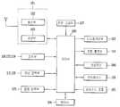
도 13은 본 발명에 관련된 휴대 단말기의 블록 구성도(block diagram)이다.13 is a block diagram of a portable terminal according to the present invention.
도 13을 참조하면, 본 발명의 일 실시예에 따른 휴대 단말기는 무선통신 모듈(181), 조작부(116,123,124), 영상 입력부(115,128), 음향입력부(125), 디스플레이부(113), 음향 출력부(114,131), 센싱유닛(186), 인터페이스(126), 방송 수신 모듈(185), 메모리(184), 전원공급부(127), 제어부(180)을 포함하여 이루어진다.13, a portable terminal according to an exemplary embodiment of the present invention includes a
제어부(180)는 통상적으로 휴대 단말기의 전반적인 동작을 제어한다. 예를 들어 음성 통화, 데이터 통신, 화상 통화 등을 위한 관련된 제어 및 처리를 수행한다.The
무선 통신 모듈(181)은 안테나를 통하여 이동통신 기지국과 무선 신호를 송/수신한다. 예를 들어 제어부(190)의 제어 하에 음성 데이터, 문자 데이터, 영상 데이터 및 제어 데이터의 송수신을 담당하며 이를 위해 송신할 신호를 변조하여 송신하는 송신부(182)와, 수신되는 신호를 복조하는 수신부(183)을 포함한다.The
조작부(116,123,124)는 도 1에 도시된 바와 같이 구성되어 사용자가 단말기의 동작 제어를 위하여 입력하는 키 입력 데이터를 제어부(180)에 제공한다. 조작부(116,123,124)는 돔 스위치(dome switch), 터치 패드(정압/정전), 조그 휠, 조그 스위치 등으로 구성된다.The
영상입력부(115,128)는 화상 통화모드 또는 촬영 모드에서 이미지 센서에 의해 얻어지는 정지영상 또는 동영상 등의 화상 프레임을 처리한다. 그리고, 처리된 화상 프레임은 디스플레이부(113)에 표시 가능한 영상 데이터로 변환되어 디스플레이부(113)로 출력된다.The
영상입력부(115,128)에서 처리된 화상 프레임은 제어부(180)의 제어에 의해 메모리(184)에 저장되거나 무선 통신 모듈(181)를 통하여 외부로 전송된다.The image frames processed by the
음향입력부(125)는 통화모드 또는 녹음모드, 음성인식 모드 등에서 마이크로폰(Microphone)에 의해 외부의 음향 신호를 입력받아 전기적인 음성 데이터로 처리한다. 그리고, 처리된 음성 데이터는 통화 모드인 경우 무선 통신 모듈(181)를 통하여 이동통신 기지국으로 송신 가능한 형태로 변환되어 무선 통신 모듈로 출력된 다. 녹음 모드인 경우 처리된 음성 데이터는 메모리(184)에 저장되도록 출력된다.The
음향입력부(125)는 외부의 음향 신호를 입력받는 과정에서 발생되는 잡음(noise)를 제거하기 위한 다양한 잡음 제거 알고리즘이 구현될 수 있다.The
디스플레이부(113)는 휴대 단말기에서 처리되는 정보를 표시 출력한다. 예를 들어 휴대 단말기가 통화 모드인 경우 제어부(180)의 제어에 의해 통화와 관련된 UI(User Interface) 또는 GUI(Graphic User Interface)를 표시 출력한다. 그리고 휴대 단말기가 화상 통화 모드 또는 촬영 모드인 경우 제어부(180)의 제어에 의해 촬영된 영상 또는 UI,GUI를 표시 출력한다. 디스플레이부(113)는 터치 스크린을 포함하여 구성되는 경우, 출력 장치 이외에 입력 장치로 사용된다.The
음향 출력부(114,131)는 호신호 수신, 통화모드 또는 녹음 모드, 음성인식 모드, 방송수신 모드 등에서 제어부(180)의 제어에 의해 무선 통신 모듈(181)로부터 수신된 음향 데이터 또는 메모리(184)에 저장된 음향 데이터를 변환하여 외부로 출력한다.The
또한, 음향 출력부(114,131)는 휴대 단말기에서 수행되는 기능(예를 들어, 호신호 수신음, 메시지 수신음 등)과 관련된 음향 신호를 출력한다. 이러한 음향 출력부(114,131)는 스피커(speaker), 리시버(Receiver), 버저(Buzzer) 등으로 포함한다.In addition, the
센싱 유닛(186)은 휴대 단말기의 개폐 상태, 휴대 단말기의 위치, 사용자 접촉 유무 등과 같이 휴대 단말기의 현 상태를 감지하여 휴대 단말기의 동작을 제어하기 위한 센싱 신호를 발생시킨다. 예를 들어 휴대 단말기가 슬라이드 폰 형태인 경우 슬라이드 폰의 개폐 여부를 센싱하여 제어부(180)로 센싱 결과를 출력하여 단말기의 동작이 제어되도록 한다. 또한 전원 공급부(127)의 전원 공급 여부, 인터 페이스(126)의 외부 기기 결합 여부 등과 관련된 센싱 기능을 담당한다.The
인터페이스(126)는 휴대 단말기 이외 유/무선 헤드셋, 외부 충전기, 유/무선 데이터 포트, 카드 소켓(예를 들어, 메모리 카드(Memory card), SIM/UIM card) 등을 휴대 단말기에 연결되는 모든 외부기기와의 인터페이스 역할을 한다. 이와 같은 인터페이스(126)는 외부 기기로부터 데이터를 전송받거나 전원을 공급받아 휴대 단말기 내부의 각 구성 요소에 전달하거나 휴대 단말기 내부의 데이터가 외부 기기로 전송되도록 한다.The
메모리(184)는 제어부(180)의 처리 및 제어를 위한 프로그램이 저장될 수도 있고, 입/출력되는 데이터들(예를 들어, 폰북, 메시지, 정지영상, 동영상 등)의 임시 저장을 위한 기능을 수행할 수도 있다.The
또한, 메모리(184)에는 본 발명과 관련된 휴대 단말기의 동작을 제어하는 프로그램이 저장된다A program for controlling the operation of the portable terminal related to the present invention is stored in the
이러한 메모리(184)는 일반적으로 알려진 하드 디스크, 카드 타입의 메모리(예를 들어 SD 또는 XD 메모리 등), 플래시 메모리, 램, 롬 등의 개념을 포함한다.
방송 수신 모듈(185)은 위성 또는 지상파 등을 통하여 전송된 방송 신호를 수신하여 음향 출력부(114,131), 디스플레이부(113)에 출력 가능한 방송 데이터 형태로 변환하여 제어부(180)에 출력한다. 또한 방송 수신 모듈(185)은 방송과 관련된 부가 데이터(예를 들면, EPG(Electric Program Guide), 채널 리스트 등)를 수신 한다. 방송 수신 모듈(185)에서 변환된 방송 데이터 및 부가 데이터는 메모리(184)에 저장될 수도 있다.The
전원 공급부(127)는 제어부(180)의 제어에 의해 외부의 전원, 내부의 전원을 인가받아 각 구성요소들의 동작에 필요한 전원을 공급한다.The
상기와 같은 휴대 단말기는 위에서 설명된 실시예들의 구성과 방법에 한정되는 것이 아니라, 상기 실시예들은 다양한 변형이 이루어질 수 있도록 각 실시예들의 전부 또는 일부가 선택적으로 조합되어 구성될 수도 있다.The above-described portable terminal is not limited to the configuration and method of the embodiments described above, but all or some of the embodiments may be selectively combined so that various modifications may be made to the embodiments.
도 1은 본 발명의 일 실시예에 관련된 휴대 단말기의 전면 사시도.1 is a front perspective view of a mobile terminal according to an embodiment of the present invention;
도 2는 본 발명의 일 실시예에 관련된 휴대 단말기의 후면 사시도.2 is a rear perspective view of a portable terminal according to an embodiment of the present invention;
도 3은 본 발명의 일실시예와 관련된 휴대 단말기의 분해 사시도.3 is an exploded perspective view of a portable terminal according to an embodiment of the present invention;
도 4는 도 3의 Ⅳ-Ⅳ 라인을 따르는 휴대 단말기의 단면도.4 is a cross-sectional view of the portable terminal according to line IV-IV in FIG. 3;
도 5a 및 5b는 일반적인 형태의 돔 스위치의 구조 및 작동 상태를 나타내는 단면도들.5A and 5B are cross-sectional views showing the structure and operating state of a dome switch in general form.
도 6은 메탈 돔의 변형에 따라 메탈 돔에 작용하는 힘의 크기를 나타낸 그래프.6 is a graph showing the magnitude of the force acting on the metal dome in accordance with the deformation of the metal dome.
도 7은 본 발명의 제1실시예와 관련된 돔 스위치의 단면도들.7 is a cross-sectional view of a dome switch in accordance with a first embodiment of the present invention.
도 8은 본 발명의 제1실시예와 관련된 돔 스위치의 메탈 돔의 변형에 따라 메탈 돔에 작용하는 힘을 측정한 그래프.8 is a graph showing a force acting on a metal dome according to a modification of the metal dome of the dome switch according to the first embodiment of the present invention.
도 9 내지 도 12는 본 발명의 제2 내지 제5실시예와 관련된 돔 스위치들의 단면도들.9 to 12 are cross-sectional views of dome switches according to second to fifth embodiments of the present invention.
도 13은 본 발명의 일 실시예에 관련된 휴대 단말기의 블록 구성도.FIG. 13 is a block diagram of a portable terminal according to an embodiment of the present invention; FIG.
Claims (10)
Translated fromKoreanPriority Applications (4)
| Application Number | Priority Date | Filing Date | Title |
|---|---|---|---|
| KR1020090034365AKR101622603B1 (en) | 2009-04-20 | 2009-04-20 | Portable terminal |
| EP10000800.2AEP2244274B1 (en) | 2009-04-20 | 2010-01-27 | Portable terminal |
| US12/696,998US8269124B2 (en) | 2009-04-20 | 2010-01-29 | Dome switch structure for a portable terminal |
| CN2010101674747ACN101866766B (en) | 2009-04-20 | 2010-04-19 | Portable terminal |
Applications Claiming Priority (1)
| Application Number | Priority Date | Filing Date | Title |
|---|---|---|---|
| KR1020090034365AKR101622603B1 (en) | 2009-04-20 | 2009-04-20 | Portable terminal |
Publications (2)
| Publication Number | Publication Date |
|---|---|
| KR20100115663A KR20100115663A (en) | 2010-10-28 |
| KR101622603B1true KR101622603B1 (en) | 2016-05-20 |
Family
ID=43134495
Family Applications (1)
| Application Number | Title | Priority Date | Filing Date |
|---|---|---|---|
| KR1020090034365AExpired - Fee RelatedKR101622603B1 (en) | 2009-04-20 | 2009-04-20 | Portable terminal |
Country Status (1)
| Country | Link |
|---|---|
| KR (1) | KR101622603B1 (en) |
Citations (1)
| Publication number | Priority date | Publication date | Assignee | Title |
|---|---|---|---|---|
| JP2003338231A (en)* | 2002-03-13 | 2003-11-28 | Matsushita Electric Ind Co Ltd | Push-on switch |
- 2009
- 2009-04-20KRKR1020090034365Apatent/KR101622603B1/ennot_activeExpired - Fee Related
Patent Citations (1)
| Publication number | Priority date | Publication date | Assignee | Title |
|---|---|---|---|---|
| JP2003338231A (en)* | 2002-03-13 | 2003-11-28 | Matsushita Electric Ind Co Ltd | Push-on switch |
Also Published As
| Publication number | Publication date |
|---|---|
| KR20100115663A (en) | 2010-10-28 |
Similar Documents
| Publication | Publication Date | Title |
|---|---|---|
| EP2244274B1 (en) | Portable terminal | |
| US8260382B2 (en) | Portable sliding wireless communication terminal | |
| KR101437991B1 (en) | Mobile terminal | |
| KR20100018389A (en) | Slide module and portable terminal having the same | |
| KR20110131750A (en) | Mobile terminal | |
| US10804047B2 (en) | Mobile terminal | |
| KR101688941B1 (en) | Manufacturing method of portable terminal | |
| KR101404743B1 (en) | Portable terminal having antenna module and antenna setting method therefor | |
| KR101561900B1 (en) | Portable terminal | |
| KR101622603B1 (en) | Portable terminal | |
| KR101545571B1 (en) | Mobile terminal | |
| KR101553951B1 (en) | Portable terminal | |
| KR20090076110A (en) | Handheld terminal | |
| KR101474440B1 (en) | Mobile terminal | |
| KR101427274B1 (en) | Mobile terminal | |
| KR101604801B1 (en) | Portable terminal | |
| KR101442543B1 (en) | Portable terminal | |
| KR101474449B1 (en) | Portable terminal | |
| KR101463816B1 (en) | Battery pack and portable terminal having the same | |
| KR101427261B1 (en) | Portable terminal | |
| KR101570378B1 (en) | Mobile terminal | |
| KR101513618B1 (en) | Portable terminal | |
| KR101474455B1 (en) | Mobile terminal | |
| KR101504213B1 (en) | Switch assembley and portable terminal having the same | |
| KR101466026B1 (en) | Portable terminal |
Legal Events
| Date | Code | Title | Description |
|---|---|---|---|
| PA0109 | Patent application | St.27 status event code:A-0-1-A10-A12-nap-PA0109 | |
| R18-X000 | Changes to party contact information recorded | St.27 status event code:A-3-3-R10-R18-oth-X000 | |
| R18-X000 | Changes to party contact information recorded | St.27 status event code:A-3-3-R10-R18-oth-X000 | |
| PG1501 | Laying open of application | St.27 status event code:A-1-1-Q10-Q12-nap-PG1501 | |
| A201 | Request for examination | ||
| E13-X000 | Pre-grant limitation requested | St.27 status event code:A-2-3-E10-E13-lim-X000 | |
| P11-X000 | Amendment of application requested | St.27 status event code:A-2-2-P10-P11-nap-X000 | |
| P13-X000 | Application amended | St.27 status event code:A-2-2-P10-P13-nap-X000 | |
| PA0201 | Request for examination | St.27 status event code:A-1-2-D10-D11-exm-PA0201 | |
| D13-X000 | Search requested | St.27 status event code:A-1-2-D10-D13-srh-X000 | |
| PN2301 | Change of applicant | St.27 status event code:A-3-3-R10-R13-asn-PN2301 St.27 status event code:A-3-3-R10-R11-asn-PN2301 | |
| D14-X000 | Search report completed | St.27 status event code:A-1-2-D10-D14-srh-X000 | |
| E902 | Notification of reason for refusal | ||
| PE0902 | Notice of grounds for rejection | St.27 status event code:A-1-2-D10-D21-exm-PE0902 | |
| E13-X000 | Pre-grant limitation requested | St.27 status event code:A-2-3-E10-E13-lim-X000 | |
| P11-X000 | Amendment of application requested | St.27 status event code:A-2-2-P10-P11-nap-X000 | |
| P13-X000 | Application amended | St.27 status event code:A-2-2-P10-P13-nap-X000 | |
| E701 | Decision to grant or registration of patent right | ||
| PE0701 | Decision of registration | St.27 status event code:A-1-2-D10-D22-exm-PE0701 | |
| PR0701 | Registration of establishment | St.27 status event code:A-2-4-F10-F11-exm-PR0701 | |
| PR1002 | Payment of registration fee | St.27 status event code:A-2-2-U10-U11-oth-PR1002 Fee payment year number:1 | |
| PG1601 | Publication of registration | St.27 status event code:A-4-4-Q10-Q13-nap-PG1601 | |
| P22-X000 | Classification modified | St.27 status event code:A-4-4-P10-P22-nap-X000 | |
| LAPS | Lapse due to unpaid annual fee | ||
| PC1903 | Unpaid annual fee | St.27 status event code:A-4-4-U10-U13-oth-PC1903 Not in force date:20190514 Payment event data comment text:Termination Category : DEFAULT_OF_REGISTRATION_FEE | |
| PC1903 | Unpaid annual fee | St.27 status event code:N-4-6-H10-H13-oth-PC1903 Ip right cessation event data comment text:Termination Category : DEFAULT_OF_REGISTRATION_FEE Not in force date:20190514 | |
| PN2301 | Change of applicant | St.27 status event code:A-5-5-R10-R13-asn-PN2301 St.27 status event code:A-5-5-R10-R11-asn-PN2301 |