KR101620609B1 - Apparatus to count the coin - Google Patents
Apparatus to count the coinDownload PDFInfo
- Publication number
- KR101620609B1 KR101620609B1KR1020140095856AKR20140095856AKR101620609B1KR 101620609 B1KR101620609 B1KR 101620609B1KR 1020140095856 AKR1020140095856 AKR 1020140095856AKR 20140095856 AKR20140095856 AKR 20140095856AKR 101620609 B1KR101620609 B1KR 101620609B1
- Authority
- KR
- South Korea
- Prior art keywords
- coin
- light
- unit
- passage
- detecting
- Prior art date
- Legal status (The legal status is an assumption and is not a legal conclusion. Google has not performed a legal analysis and makes no representation as to the accuracy of the status listed.)
- Active
Links
Images


Classifications
- G—PHYSICS
- G07—CHECKING-DEVICES
- G07D—HANDLING OF COINS OR VALUABLE PAPERS, e.g. TESTING, SORTING BY DENOMINATIONS, COUNTING, DISPENSING, CHANGING OR DEPOSITING
- G07D9/00—Counting coins; Handling of coins not provided for in the other groups of this subclass
- G—PHYSICS
- G07—CHECKING-DEVICES
- G07D—HANDLING OF COINS OR VALUABLE PAPERS, e.g. TESTING, SORTING BY DENOMINATIONS, COUNTING, DISPENSING, CHANGING OR DEPOSITING
- G07D1/00—Coin dispensers
- G—PHYSICS
- G07—CHECKING-DEVICES
- G07D—HANDLING OF COINS OR VALUABLE PAPERS, e.g. TESTING, SORTING BY DENOMINATIONS, COUNTING, DISPENSING, CHANGING OR DEPOSITING
- G07D3/00—Sorting a mixed bulk of coins into denominations
- G07D3/16—Sorting a mixed bulk of coins into denominations in combination with coin-counting
- G—PHYSICS
- G07—CHECKING-DEVICES
- G07D—HANDLING OF COINS OR VALUABLE PAPERS, e.g. TESTING, SORTING BY DENOMINATIONS, COUNTING, DISPENSING, CHANGING OR DEPOSITING
- G07D5/00—Testing specially adapted to determine the identity or genuineness of coins, e.g. for segregating coins which are unacceptable or alien to a currency
- G07D5/02—Testing the dimensions, e.g. thickness, diameter; Testing the deformation
- G—PHYSICS
- G07—CHECKING-DEVICES
- G07D—HANDLING OF COINS OR VALUABLE PAPERS, e.g. TESTING, SORTING BY DENOMINATIONS, COUNTING, DISPENSING, CHANGING OR DEPOSITING
- G07D9/00—Counting coins; Handling of coins not provided for in the other groups of this subclass
- G07D9/008—Feeding coins from bulk
- G—PHYSICS
- G07—CHECKING-DEVICES
- G07D—HANDLING OF COINS OR VALUABLE PAPERS, e.g. TESTING, SORTING BY DENOMINATIONS, COUNTING, DISPENSING, CHANGING OR DEPOSITING
- G07D9/00—Counting coins; Handling of coins not provided for in the other groups of this subclass
- G07D9/04—Hand- or motor-driven devices for counting coins
Landscapes
- Physics & Mathematics (AREA)
- General Physics & Mathematics (AREA)
- Testing Of Coins (AREA)
- Control Of Vending Devices And Auxiliary Devices For Vending Devices (AREA)
- Slot Machines And Peripheral Devices (AREA)
Abstract
Translated fromKoreanDescription
Translated fromKorean본 발명은 동전 계수 장치에 관한 것으로, 더 상세하게는 동전의 선별과정에서 동전이송통로를 통하여 배출되는 동전의 검출신뢰성을 높여 배출되는 동전을 정확하게 계수 할 수 있는 동전계수장치에 관한 것이다.BACKGROUND OF THE INVENTION 1. Field of the Invention The present invention relates to a coin counting apparatus, and more particularly, to a coin counting apparatus capable of accurately counting discharged coins by increasing the detection reliability of coins discharged through a coin transfer passage in the process of sorting coins.
일반적으로, 대중 교통수단의 지불수단으로서 비접촉식 카드, 회수권, 지폐, 동전 등이 사용되고 있다. 이 지불수단 중 동전을 사용하는 경우, 다양한 종류의 동전이 유입되게 되므로 동전을 계수하는데 많은 어려움이 있다.In general, contactless cards, coupon tickets, banknotes, coins and the like are used as payment means for public transportation means. When using a coin among these payment means, various types of coins are introduced, which makes it difficult to count coins.
특히, 동전으로 교통비를 지불하는 경우, 지불된 교통비가 정확한 요금인지의 확인이 용이하지 않고, 나아가서는 운전자에 의한 안전사고의 위험성이 증가하는 문제점이 있다.Particularly, in the case of paying the transportation expenses with the coin, it is not easy to confirm whether the transportation cost paid is the correct fare, and there is a problem that the risk of the safety accident by the driver increases.
대한민국 특허공개 제 2008-0102511호에는 동전선별장치가 게시되어 있다. 동전선별장치는 그 내측에 원형의 수용부가 형성되고 상기 수용부의 내측 벽을 따라 그 저면에 크기별로 동전 홈이 각 천공된 선별 하우징과, 상기 수용부에 회전가능하게 장착되어 상기 수용부로 유입된 동전을 상기 수용부의 내측벽을 따라 이송시켜 상기 동전 홈을 통해 화종별로 분리 배출하기 위한 분리회전판을 구비한다.Korean Patent Laid-Open Publication No. 2008-0102511 discloses a coin sorting device. The coin sorting apparatus comprises a sorting housing having a circular receiving portion formed inside thereof and having perforated coin grooves formed in its bottom surface along the inner wall of the receiving portion, the coin receiving portion being rotatably mounted on the receiving portion, And a separating rotary plate for separating and discharging the coins along the inner wall of the accommodating portion through the coin grooves.
그리고, 대한민국 공개특허 제 2007-0106208호에는 동전계수장치가 게시되어 있다. 게시된 동전계수장치는 원심력에 의해 동전을 투출하기 위한 회전판과, 투출된 동전을 고속으로 이송시킬 수 있도록 그 회전력에 의해 재차 투출하기 위한 고속전송롤러 및 투출된 동전을 공지의 계수감지부 측으로 안내하기 위한 이송통로가 구비된 것으로, 상기 이송통로는 그 선단에 곡면부가 마련되되, 상기 고속전송롤러에서 투출된 동전이 상기 곡면부로 진입 시 그 충격을 완화하여 일측벽을 따라 이송하도록 상기 곡면부 상에 충격완충부재가 구비된다.Korean Patent Publication No. 2007-0106208 discloses a coin counting apparatus. The posted coin counting apparatus includes a rotating plate for discharging coins by centrifugal force, a high-speed transfer roller for discharging the coins again by the rotational force so that the discharged coins can be transferred at a high speed, and a coin sensor Wherein the conveying path is provided with a curved surface at the tip thereof, wherein the curved surface portion is provided on the curved surface portion so as to relieve the shock when the coin drawn out from the high-speed transfer roller enters the curved surface portion, A shock buffering member is provided.
그리고 대한민국 특허등록 제 0663636호에는 고속동전계수장치가 게시되어 있으며, 대한민국 특허등록 제 09109630호에는 동전을 이용한 계수장치 및 그 제어방법이 게시되어 있다.Korean Patent Registration No. 0663636 discloses a high-speed coin counting device, and Korean Patent Registration No. 09109630 discloses a coin counting device and a control method thereof.
상술한 바와 같이 구성된 종래의 동전계수장치들은 동전을 선별하는 과정에서 동전이송통로를 통과하는 동전의 재질에 따라 검출이 이루어지지 않은 경향이 있어 동전의 검출 및 계수에 따른 신뢰성을 높일 수 없다.The conventional coin counting apparatus configured as described above tends not to be detected according to the material of the coin passing through the coin transfer path in the course of selecting the coin so that the reliability according to the detection and the counting of the coin can not be increased.
본 발명의 해결하고자하는 기술적 과제는 동전이송통로를 통과하는 동전의 종류에 따른 검출신뢰성을 향상시켜 동전계수효율을 높일 수 있는 동전계수장치를 제공함에 있다.SUMMARY OF THE INVENTION The present invention has been made in view of the above problems, and it is an object of the present invention to provide a coin counting apparatus capable of improving the detection reliability according to the type of coin passing through the coin transfer passage,
상기 기술적 과제를 해결하기 위한 본 발명의 동전계수장치는 원형상의 수용부가 형성되고 수용부를 형성하는 격벽에 마련된 배출구와 연결되며 곡선상의 동전이송통로가 형성된 프레임과;According to an aspect of the present invention, there is provided a coin counting apparatus comprising: a frame having a circular receiving portion formed therein and connected to an outlet provided in a partition wall forming a receiving portion, the curved coin conveying passage being formed;
상기 프레임의 수용부에 회전가능하게 장착되고 투입된 동전을 그 회전력에 의해 상기 배출구 측으로 이송시킬 수 있도록 상면에 동전수용홈이 형성된 이송회전판과;A transfer rotary plate rotatably mounted in the receiving portion of the frame and having a coin receiving groove formed on an upper surface thereof for transferring the inputted coin to the discharge port side by the rotational force;
상기 배출구 측으로 이송되어 투출된 동전을 그 회전력에 의해 밀어줌으로써 상기 동전이 상기 동전이송통로 상에 장착된 계수감지부를 일정 속도로 통과하도록 하는 동전토출롤러유닛과;A coin discharge roller unit for causing the coin to pass the coin detecting unit mounted on the coin transfer passage at a constant speed by pushing the coin transferred and discharged to the discharge port by its rotational force;
상기 동전이송통로 상에 통로방향에 대해 법선 또는 경사방향으로 복수개의 광을 조사하는 광조사부와, 상기 동전이송통로로의 동전 통과 시 반사되는 광을 검출하여 동전을 계수할 수 있도록 하는 광검출부를 구비한 동전검출유닛;을 포함한 것을 그 특징으로 한다.A light irradiating unit for irradiating a plurality of light beams in a normal or oblique direction with respect to the path direction on the coin transfer path; and a photodetector unit for detecting light reflected when the coin passes through the coin transfer path, And a coin detecting unit provided therein.
본 발명에 있어서, 상기 광조사부는 동전이송통로의 이송방향에 대해 경사방향 또는 법선방향으로 형성되는 광조사슬릿과, 상기 광조사슬릿이 형성된 동전이송통로의 하면에 설치되어 광을 조사하는 것으로, 길이 방향으로 소정의 피치로 노치가 형성되어 이루어진 광분기부들이 형성된 광파이버와, 상기 광파이버의 일측에 결합되어 광을 조사하기 위한 광원부와, 상기 광원부와 광파이버를 고정하는 하우징을 구비하며,In the present invention, the light irradiating unit may include a light irradiating slit formed in an oblique direction or a normal direction with respect to the conveying direction of the coin conveying path, and a coin conveying path provided on the lower surface of the coin conveying path, A light source unit for irradiating light to one side of the optical fiber; and a housing for fixing the light source unit and the optical fiber, wherein the light source unit includes a plurality of optical splitters,
상기 광검출부는 상기 광파이버의 광분기부로부터 조사된 후 광조사슬릿을 지나가는 동전으로부터 반사되는 광을 검출하는 광검출센서를 구비 한다.The photodetector includes a photodetection sensor for detecting light reflected from a coin passing through the light irradiation slit after being irradiated from the light splitting portion of the optical fiber.
본 발명에 따른 동전계수장치는 동전의 계수를 위해 동전의 이동시 발생되는 트러블을 근본적으로 방지할 수 있으며, 나아가서는 동전의 계수에 따른 신뢰성을 향상시킬 수 있다.The coin counting apparatus according to the present invention can fundamentally prevent troubles caused when moving a coin for counting coins, and can further improve reliability according to the coin count.
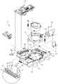
도 1은 본 발명에 동전계수장치의 분리사시도,
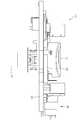
도 2는 본 발명에 따른 동전계수장치의 측면도,
도 3은 동전이송통로에 동전검출유닛이 설치된 상태를 나타내 보인 일부절제 사시도,
도 4는 본 발명에 따른 동전검출유닛 작동상태를 나타내 보인 측면도.1 is an exploded perspective view of a coin counting apparatus according to the present invention,
2 is a side view of a coin counting apparatus according to the present invention,
3 is a partially cutaway perspective view showing a state in which the coin detecting unit is installed in the coin transfer passage,
4 is a side view showing the operating state of the coin detecting unit according to the present invention.
본 발명에 따른 동전계수장치는 동전의 계수를 위해 동전이송통로를 통하여 투출되는 동전을 검출하는 수단이 개량된 것으로, 그 일 실시예를 도 1 내지 도 3에 나타내 보였다.The coin counting apparatus according to the present invention is an improvement of a means for detecting a coin to be output through a coin transfer passage for counting coins, one embodiment of which is shown in Figs.
도면을 참조하면, 본 발명에 따른 동전계수장치(10)는 소정의 직경을 가지는 원형상의 수용부(21)가 형성되고, 이 수용부(21)와 연통되는 동전이송통로(22)가 형성되는 프레임(20)을 구비한다. 상기 동전이송통로(22)는 수용부(21)를 이루는 격벽의 일측에 배출구(23)가 형성되어 수용부(21)와 연결된다. 상기 동전이송통로(22)는 상기 수용부(21)로부터 소정의 곡선의 형상으로 형성되는데, 이 동전이송통로는 인벌루트곡선의 궤적 또는 스크롤 형상의 궤적을 따라 형성될 수 있다.A
그리고 상기 프레임(20)의 수용부(21)에는 이송회전판(30)이 프레임(20)의 하부에 설치되는 구동모터(31)에 의해 회전가능하게 설치되는데, 이 이송회전판(30)의 상면측의 가장자리에는 동전수용홈(32)을 구획하는 구획돌기(33)가 형성된다. 상기 구획돌기(33)의 높이는 실질적으로 동전의 높이와 동일한 높이를 가진다. 또한 동전수용홈(32)은 사용되는 가장작은 동전의 두 개가 수용되지 않도록 두 개의 직경의 합보다 작은 작경을 갖도록 형성함이 바람직하다.A conveying
또한, 이송회전판(30)의 상면에 형성된 동전수용홈(32)은 입구측 보다 상대적으로 출구측이 넓게 형성되어 이송회전판(30)의 회전으로 배출구(23) 측에 위치 시 수용된 동전이 원심력에 의해 배출구(23) 측으로 투출된다. 이를 더욱 상세하게 설명하면, 상기 동전 수용홈(32)은 수용부(21)의 내측벽과 구획돌기에 의해 배출측 즉, 이송회전판(30)의 가장자리측이 밀폐된 상태이나 배출구(23)는 프레임(20)의 수용부를 이루는 측벽이 절개되어 형성된 것이므로 동전수용홈(21)이 배출구(23)측에 위치 시 그 하방이 개방상태를 유지하게 된다.The
그리고 상기 동전이송통로(22)와 인접되는 프레임(20)에는 배출구(23) 측으로 이송되어 토출(투출)되는 동전을 그 회전력에 의해 밀어줌으로써 동전(100)이 계수감지부(50)를 일정 속도로 신속히 통과하여 감지되도록 한 동전토출롤러유닛(40)이 설치된다. 상기 동전토출롤러유닛(40)은 프레임(20)에 설치되는 모터(41)와, 상기 모터(41)의 회전축(42a)에 설치되는 회전롤러(42)를 구비한다.The
상기 동전토출롤러유닛(40)은 프레임(20)의 배출구(23) 측에 설치되어, 이송회전판(30)의 동전 수용홈(32)으로부터 투출된 동전을 그 회전력에 의해 재차 밀어줌으로써 동전이송통로(22)를 따라 일정 속도로 신속히 계수감지부(50)를 통과하여 감지되도록 한다. 즉, 동전토출롤러유닛(40)은 그 롤러(42)가 배출구(23)의 면과 수평상태로 위치되어 동전 유입 시 그 회전력에 의해 일정 속도로 재차 밀어줌으로써 계수시간을 효과적으로 단축할 수 있게 된다. 예컨대, 이송회전판(30)의 회전력만으로 동전(100)을 이송시켜 계수감지부(50)를 통과하도록 하는 경우 동전(100)의 크기 및 중량에 따라 속도 편차를 갖게 되어 동전의 계수의 오류가 유발될 수 있는데, 상기 동전토출롤러유닛(50)에 의해 동전을 밀어줌으로써 계수의 유류를 줄일 수 있다.The coin
그리고 도면에는 도시되어 있지 않으나 상기 프레임(20)의 수용부(21)에는 이송회전판(30)으로의 동전 투입 시 이를 감지하여 이송회전판(30)을 회전시킬 수 있도록 상기 구동모터(31)를 구동시키 위한 센서가 설치될 수 있다. 상기 센서는 근접센서를 사용함이 바람직한데, 이에 한정되지는 않는다. 상기 근접센서에 의해 동전의 투입이 감지되면, 이 근접센서로부터 발생되는 신호는 제어부(미도시)에 의해 인식되고, 제어부는 구동모터(31)를 구동시킴으로써 이송회전판(30)을 반시계방향(도 1참조)으로 회전시키게 된다. 프레임(20)에 설치되어 투입된 불량동전이나 이물질을 반환할 수 강제반환부(미도시)가 더 구비될 수 있다.Although not shown in the drawing, the
한편, 상기 동전계수부(50)는 동전이송통(22)로 상에 통로방향에 대해 법선 또는 경사방향으로 복수개의 광을 조사하는 광조사부(70)와, 상기 동전이송통로(22)로의 동전의 통과 시 반사되는 광을 검출하여 동전을 계수할 수 있도록 하는 광검출부(80)를 구비한 동전검출유닛(60)을 더 구비한다.On the other hand, the
상기 동전검출유닛(60)을 이루는 상기 광조사부(70)는 도 1 , 도 3 내지 도 4에 도시된 바와 같이 동전이송통로(22)의 이송방향에 대해 경사방향 또는 법선방향으로 광조사슬릿(71)이 형성되고, 상기 광조사슬릿(71)이 형성된 동전이송통로(22)의 하면에는 상기 광조사슬릿(71)의 길이 방향으로 따라 상기 광조사슬릿을 통하여 수직 상방으로 복수의 광을 조사하는 광파이버(72)를 구비한다. 상기 광파이버(72)는 그 길이 방향으로 소정의 피치로 노치(notch)가 형성되어 이루어진 광분기부(73)가 형성되는데, 상기 광분기부(73)를 위한 노치는 후술하는 광원부로부터조사되는 광이 분기되어 조사될 수 있도록 형성된다. 예컨대, 광원부로부터 노치의 깊이를 접차적으로 크게 형성하여 형성할 수 있다. 그리고 상기 광파이버(72)의 일측에는 상기 광파이버(72)에 광을 조사하기 위한 광원부(74)가 구비되는데, 이 광원부(74)는 발광다이오드로 이루어질 수 있는데, 이에 한정되는 것은 아니다.The light irradiating
상기 광파이버(72)에 형성된 광분기부(73)의 수직상부에 형성되지 않고 측면에 형성되어 광조사슬릿(71)을 상부로 지나가는 동전에 의해 경사각도를 가지고 반사될 수 있도록 함이 바람직하다. 상기 광원부(74)와 광파이버(72)는 도 1 및 도 3에 도시된 바와 같이 하우징(75)에 지지되어 동전이송통로(22)의 하부에 설치될 수 있다.It is preferable not to vertically form the
상기 광검출부(80)는 상기 광분기부(73)들로부터 분기되어 광조사슬릿(71)의 상부을 통과하는 동전에 반사된 광을 검출하는 것으로, 광분기부(73)와 대응되는 개수로 설치되는 광검출센서(81)를 구비한다. 광검출센서는 포토다이오드 등으로 이루어질 수 있다. 상기 광검출센서(81)들은 각 광분기부(73)와 대응되도록 설치된다.The
한편, 상기 광조사슬릿(71)의 상부측 가장자리의 높이가 하부측 가장자리의 높이보다 높게 형성되어 동전이송통로(22)를 통한 동전(100)의 이동시 광조사슬릿에 의해 간섭이 발생되지 않도록 함이 바람직하다. 그리고 상기 계수감지부(50)는 상기 동전검출유닛(60)에 검출된 신호를 이용하여 동전을 계수하는 제어부를 더 구비한다.On the other hand, the height of the upper side edge of the
상기와 같이 구성된 본 발명에 따른 동전계수장치의 작용효과를 첨부된 도면을 참조하여 설명하면 다음과 같다. The operation and effect of the coin counting apparatus according to the present invention will now be described with reference to the accompanying drawings.
먼저, 대중 교통수단에 설치된 동전계수장치에 이용객(승객)이 동전 계수장치(10)의 동전투입구(11)에 적정 요금의 동전을 투입하면, 동전(100)들은 동전투입구(11) 하단에 위치한 이송회전판(30)으로 떨어진다. 이때, 프레임(20)의 수용부(21) 에 설치된 근접센서에 의해 이송회전판(30)로의 동전 투입이 감지되면, 근접센서의 감지신호에 근거하여 제어부(미도시)는 구동모터(31)를 구동시켜 이송회전판(30)를 일방향으로 회전시키고 동시에 동전토출롤러유닛(40)을 구동시켜 회전롤러(41)를 일방향으로 회전시킨다.First, when a user (passenger) inserts a proper coin into the
이에 따라, 이송회전판(20) 내의 동전들은 원심력에 의해 각기 외측으로 밀려 일정 간격으로 배열된 동전 수용홈(32)에 수용되고, 이송되어, 순차적으로 토출구(23)로 투출된다.Accordingly, the coins in the conveying
토출구(23)를 통해 투출된 동전(100)은 동전토출롤러유닛(40)에 의해 일정 속도로 빠르게 이송되고, 이송통로(22)의 곡면부를 따라 일측벽에 밀착된 상태로 계수감지부(50)를 통과한다. 계수감지부(50)는 일정 속도로 통과하는 동전의 가액을 감지하고, 제어부는 계수감지부(50)를 통해 감지된 동전의 가액을 집계한 뒤 이를 표시부(미도시)를 통해 디스플레이 한다. 그 결과, 대중 교통수단의 운전자는 승객이 지불한 금원이 적정 요금인지를 용이하게 판별할 수 있게 된다.The
상술한 바와 같이 동전(100)을 계수하는 과정에서 동전이송통로(22)에는 동전검출유닛(60)이 설치되어 있으므로 동전(100)의 계수에 따른 신뢰성을 더욱 높일 수 있다.As described above, since the
즉, 동전이송통로(22)에 형성된 광조사슬릿(71)으로 광조사부(70)를 이루는 광파이버(72)의 광분기부(73)들로부터 광이 조사된 상태에서 동전이송통로(22)로 동전이 이송되게 되면, 이 동전(100)에 의해 광이 반사되고, 이 반사된 광은 광검출부(80)들에 의해 검출된다.That is, the light irradiation slit 71 formed in the
이러한 과정에서 상기 동전(100)의 크기에 따라 각 광분기부(73)들로부터 반사되는 반사광의 수가 많아지게 되고, 광검출부에 의해 검출되는 수가 많아지게 된다. 예컨대, 10원의 동전이 이동하는 경우, 2개의 광분기부(73)로부터 분기된 광이 검출되었다면, 100원의 동전이 이동하는 경우 3개 내지 4개의 광분기부(73)로부터 분기된 광이 검출되고, 500원의 동전이 이동하는 경우 5개 내지 6개의 광분기부(73)로부터 분기된 광이 검출되어 동전을 정확하게 식별할 수 있게 된다.In this process, the number of reflected light reflected from each light splitting
이와 같이 광검출부(70)에 의해 검출된 광 즉, 광분기부(73)로부터 검출된 광의 검출 갯수가 동전의 크기에 따라 달라지게 되므로 이러한 광검출 개수는 제어부에 의해 동전계수부의 정보와 같이 정확한 동전을 계수할 수 있게 된다.Since the number of detected lights of the light detected by the
따라서 동전의 계수장치는 동전의 재질에 관계없이 계수에 따른 신뢰성을 높일 수 있다.Therefore, the coin counting device can increase the reliability according to the coefficient regardless of the material of the coin.
한편, 불량동전이나 이물질(특히, 금속성 나사, 못, 너트 등)이 정상적인 동전과 함께 이송회전판(30)에 투입된 동전은 도시되지 않은 강제반환부에 의해 반환된다.On the other hand, coins inserted into the conveying
상기와 같이 본 발명의 동전계수장치는 투입된 동전을 일정간격으로 신속히 이송시켜 계수되도록 하고, 동전의 계수가 정확하게 이루어지게 되므로 동전의 계수에 따른 신뢰성을 향상시킬 수 있다.As described above, according to the coin counting apparatus of the present invention, the input coins are rapidly transferred at constant intervals to be counted, and the coins are accurately counted, so that reliability according to the coin count can be improved.
본 발명은 도면에 도시된 실시예를 참고로 설명되었으나 이는 예시적인 것에 불과하며, 본 기술 분야의 통상의 지식을 가진 사람이라면 이로부터 다양한 변형 및 균등한 타 실시예가 가능하다는 점을 이해할 것이다. 따라서, 본 발명의 진정한 기술적 보호 범위는 첨부된 등록 청구 범위의 기술적 사상에 의해 정해져야 할 것이다.While the present invention has been particularly shown and described with reference to exemplary embodiments thereof, it is evident that many alternatives, modifications and variations will be apparent to those skilled in the art. Accordingly, the true scope of the present invention should be determined by the technical idea of the appended claims.
본 발명에 따른 동전계수장치는 동전뿐만아니라 동전과 유사한 칩등의 계수장치에 널리 적용 가능하다.
The coin counting apparatus according to the present invention can be widely applied not only to coins but also to coin counting devices such as coins.
Claims (3)
Translated fromKorean상기 프레임의 수용부에 회전가능하게 장착되고 투입된 동전을 그 회전력에 의해 상기 배출구 측으로 이송시킬 수 있도록 상면에 동전수용홈이 형성된 이송회전판과;
상기 배출구 측으로 이송되어 투출된 동전을 그 회전력에 의해 밀어줌으로써 상기 동전이 상기 동전이송통로 상에 장착된 계수감지부를 일정 속도로 통과하도록 하는 동전토출롤러유닛과;
상기 동전이송통로 상에 통로방향에 대해 법선 또는 경사방향으로 복수개의 광을 조사하는 광조사부와, 상기 동전이송통로로의 동전 통과 시 반사되는 광을 검출하여 동전을 계수할 수 있도록 하는 광검출부를 구비한 동전검출유닛;을 포함하며,
상기 광조사부는 동전이송통로의 이송방향에 대해 경사방향 또는 법선방향으로 형성되는 광조사슬릿과, 상기 광조사슬릿이 형성된 동전이송통로의 하면에 설치되어 광을 조사하는 것으로, 길이 방향으로 소정의 피치로 노치가 형성되어 이루어진 광분기부들이 형성된 광파이버와, 상기 광파이버의 일측에 결합되어 광을 조사하기 위한 광원부와, 상기 광원부와 광파이버를 고정하는 하우징을 구비하며,
상기 광검출부는 상기 광파이버의 광분기부로부터 조사된 후 광조사슬릿을 지나가는 동전으로부터 반사되는 광을 검출하는 광검출센서를 구비한 것을 특징으로하는 동전계수장치.A frame having a circular receiving portion formed therein and connected to a discharge port provided in a partition wall forming a receiving portion and having a curved coin conveying passage formed therein;
A transfer rotary plate rotatably mounted in the receiving portion of the frame and having a coin receiving groove formed on an upper surface thereof for transferring the inputted coin to the discharge port side by the rotational force;
A coin discharge roller unit for causing the coin to pass the coin detecting unit mounted on the coin transfer passage at a constant speed by pushing the coin transferred and discharged to the discharge port by its rotational force;
A light irradiating unit for irradiating a plurality of light beams in a normal or oblique direction with respect to the path direction on the coin transfer path; and a photodetector unit for detecting light reflected when the coin passes through the coin transfer path, And a coin detecting unit,
The light irradiation part is provided on a lower surface of a coin transfer path formed with the light irradiation slit and is provided with a light irradiation slit formed in an oblique direction or a normal direction with respect to a transfer direction of the coin transfer path, And a housing for fixing the light source unit and the optical fiber, wherein the light source unit is coupled to one side of the optical fiber and irradiates light,
Wherein the photodetecting unit comprises a photodetection sensor for detecting light reflected from a coin passing through the light irradiation slit after being irradiated from the light splitting unit of the optical fiber.
상기 광조사슬릿의 상부측 가장자리의 높이가 하부측 가장자리의 높이보다 높게 형성된 것을 특징을 하는 동전계수장치.
The method according to claim 1,
And the height of the upper side edge of the light irradiation slit is formed higher than the height of the lower side edge.
Priority Applications (4)
| Application Number | Priority Date | Filing Date | Title |
|---|---|---|---|
| KR1020140095856AKR101620609B1 (en) | 2014-07-28 | 2014-07-28 | Apparatus to count the coin |
| US15/328,910US9911264B2 (en) | 2014-07-28 | 2015-07-27 | Coin counting apparatus |
| CN201580040395.0ACN106575460A (en) | 2014-07-28 | 2015-07-27 | Coin counting apparatus |
| PCT/KR2015/007769WO2016018011A1 (en) | 2014-07-28 | 2015-07-27 | Coin counting apparatus |
Applications Claiming Priority (1)
| Application Number | Priority Date | Filing Date | Title |
|---|---|---|---|
| KR1020140095856AKR101620609B1 (en) | 2014-07-28 | 2014-07-28 | Apparatus to count the coin |
Publications (2)
| Publication Number | Publication Date |
|---|---|
| KR20160013704A KR20160013704A (en) | 2016-02-05 |
| KR101620609B1true KR101620609B1 (en) | 2016-05-23 |
Family
ID=55217824
Family Applications (1)
| Application Number | Title | Priority Date | Filing Date |
|---|---|---|---|
| KR1020140095856AActiveKR101620609B1 (en) | 2014-07-28 | 2014-07-28 | Apparatus to count the coin |
Country Status (4)
| Country | Link |
|---|---|
| US (1) | US9911264B2 (en) |
| KR (1) | KR101620609B1 (en) |
| CN (1) | CN106575460A (en) |
| WO (1) | WO2016018011A1 (en) |
Cited By (1)
| Publication number | Priority date | Publication date | Assignee | Title |
|---|---|---|---|---|
| KR102135479B1 (en) | 2020-05-09 | 2020-07-17 | 주식회사 디퍼아이 | Apparatus for artificial intelligence counting coins and method thereof |
Families Citing this family (2)
| Publication number | Priority date | Publication date | Assignee | Title |
|---|---|---|---|---|
| DE202015101489U1 (en)* | 2015-03-24 | 2016-06-28 | Crane Payment Innovations Gmbh | Device for determining the level of coin tubes |
| KR102203230B1 (en)* | 2019-04-12 | 2021-01-13 | 은남표 | apparatus to count the coin |
Citations (2)
| Publication number | Priority date | Publication date | Assignee | Title |
|---|---|---|---|---|
| JP2003196699A (en) | 2001-12-26 | 2003-07-11 | Nippon Conlux Co Ltd | Coin discriminating method, and coin discriminating device |
| KR100663636B1 (en)* | 2006-04-13 | 2007-01-05 | (주) 인포웨이 | Coin counter |
Family Cites Families (11)
| Publication number | Priority date | Publication date | Assignee | Title |
|---|---|---|---|---|
| JPH0782560B2 (en)* | 1988-03-17 | 1995-09-06 | 沖電気工業株式会社 | Coin identification device |
| JP4044322B2 (en)* | 2001-11-28 | 2008-02-06 | グローリー株式会社 | Coin processing equipment |
| JP4226454B2 (en)* | 2003-12-15 | 2009-02-18 | アルゼ株式会社 | Coin dispensing device |
| JP4443337B2 (en)* | 2004-07-22 | 2010-03-31 | 株式会社バンダイナムコゲームス | Display device and game device |
| KR20070106208A (en) | 2006-04-28 | 2007-11-01 | (주) 인포웨이 | Coin Counter with Shock Absorber |
| KR20080102511A (en) | 2007-05-21 | 2008-11-26 | (주) 인포웨이 | Coin sorting device for coin counter |
| CN201210313Y (en)* | 2008-05-05 | 2009-03-18 | 万创(香港)有限公司 | Coin sorting and counting device |
| ITBO20080288A1 (en)* | 2008-05-12 | 2009-11-13 | Massimo Cosi | COIN COUNTING AND METHOD AND METHOD. |
| ITBO20080448A1 (en)* | 2008-07-14 | 2010-01-15 | Alberici S P A | DISPENSER AND COIN METER DEVICE |
| CN201383176Y (en)* | 2008-11-19 | 2010-01-13 | 苏州日宝科技有限责任公司 | Coin sorting and counting device capable of sorting and counting mixed coins |
| KR100910963B1 (en) | 2009-01-07 | 2009-08-05 | (주)솔몬컴 | Coin counting device using camera and its control method |
- 2014
- 2014-07-28KRKR1020140095856Apatent/KR101620609B1/enactiveActive
- 2015
- 2015-07-27USUS15/328,910patent/US9911264B2/enactiveActive
- 2015-07-27WOPCT/KR2015/007769patent/WO2016018011A1/enactiveApplication Filing
- 2015-07-27CNCN201580040395.0Apatent/CN106575460A/enactivePending
Patent Citations (2)
| Publication number | Priority date | Publication date | Assignee | Title |
|---|---|---|---|---|
| JP2003196699A (en) | 2001-12-26 | 2003-07-11 | Nippon Conlux Co Ltd | Coin discriminating method, and coin discriminating device |
| KR100663636B1 (en)* | 2006-04-13 | 2007-01-05 | (주) 인포웨이 | Coin counter |
Cited By (1)
| Publication number | Priority date | Publication date | Assignee | Title |
|---|---|---|---|---|
| KR102135479B1 (en) | 2020-05-09 | 2020-07-17 | 주식회사 디퍼아이 | Apparatus for artificial intelligence counting coins and method thereof |
Also Published As
| Publication number | Publication date |
|---|---|
| WO2016018011A1 (en) | 2016-02-04 |
| CN106575460A (en) | 2017-04-19 |
| KR20160013704A (en) | 2016-02-05 |
| US20170228955A1 (en) | 2017-08-10 |
| US9911264B2 (en) | 2018-03-06 |
Similar Documents
| Publication | Publication Date | Title |
|---|---|---|
| US9501885B1 (en) | Systems, methods and devices for processing coins utilizing near-normal and high-angle of incidence lighting | |
| US10055921B2 (en) | Coin processing apparatus | |
| US9922484B2 (en) | Coin processing apparatus | |
| KR101620609B1 (en) | Apparatus to count the coin | |
| JP6296658B2 (en) | Coin handling machine | |
| EP2951795B1 (en) | Conveying money items | |
| CN106560867A (en) | Coin Processing Apparatus | |
| KR20070106208A (en) | Coin Counter with Shock Absorber | |
| JP6393977B2 (en) | Coin processing equipment | |
| CA2932503C (en) | Coin processing device and corresponding method for classifying coins | |
| KR101609458B1 (en) | Coin handling apparatus and financial device | |
| JP6841172B2 (en) | Coin processing device | |
| ES2773288T3 (en) | Device for separating and distributing coins | |
| KR101559147B1 (en) | Apparatus to count the coin | |
| JP2007164638A (en) | Coin selector | |
| JP4741820B2 (en) | Coin delivery device and coin processing device | |
| JP5095336B2 (en) | Coin slot device such as vending machine | |
| JP2006285759A (en) | Coin collection processor | |
| KR20190047563A (en) | apparatus to count the coin | |
| HK1107864B (en) | A coin processing device |
Legal Events
| Date | Code | Title | Description |
|---|---|---|---|
| A201 | Request for examination | ||
| PA0109 | Patent application | St.27 status event code:A-0-1-A10-A12-nap-PA0109 | |
| PA0201 | Request for examination | St.27 status event code:A-1-2-D10-D11-exm-PA0201 | |
| R18-X000 | Changes to party contact information recorded | St.27 status event code:A-3-3-R10-R18-oth-X000 | |
| D13-X000 | Search requested | St.27 status event code:A-1-2-D10-D13-srh-X000 | |
| D14-X000 | Search report completed | St.27 status event code:A-1-2-D10-D14-srh-X000 | |
| E902 | Notification of reason for refusal | ||
| PE0902 | Notice of grounds for rejection | St.27 status event code:A-1-2-D10-D21-exm-PE0902 | |
| PG1501 | Laying open of application | St.27 status event code:A-1-1-Q10-Q12-nap-PG1501 | |
| E13-X000 | Pre-grant limitation requested | St.27 status event code:A-2-3-E10-E13-lim-X000 | |
| P11-X000 | Amendment of application requested | St.27 status event code:A-2-2-P10-P11-nap-X000 | |
| P13-X000 | Application amended | St.27 status event code:A-2-2-P10-P13-nap-X000 | |
| E701 | Decision to grant or registration of patent right | ||
| PE0701 | Decision of registration | St.27 status event code:A-1-2-D10-D22-exm-PE0701 | |
| GRNT | Written decision to grant | ||
| PR0701 | Registration of establishment | St.27 status event code:A-2-4-F10-F11-exm-PR0701 | |
| PR1002 | Payment of registration fee | St.27 status event code:A-2-2-U10-U11-oth-PR1002 Fee payment year number:1 | |
| R18-X000 | Changes to party contact information recorded | St.27 status event code:A-5-5-R10-R18-oth-X000 | |
| PG1601 | Publication of registration | St.27 status event code:A-4-4-Q10-Q13-nap-PG1601 | |
| FPAY | Annual fee payment | Payment date:20190318 Year of fee payment:4 | |
| PR1001 | Payment of annual fee | St.27 status event code:A-4-4-U10-U11-oth-PR1001 Fee payment year number:4 | |
| PR1001 | Payment of annual fee | St.27 status event code:A-4-4-U10-U11-oth-PR1001 Fee payment year number:5 | |
| PR1001 | Payment of annual fee | St.27 status event code:A-4-4-U10-U11-oth-PR1001 Fee payment year number:6 | |
| PR1001 | Payment of annual fee | St.27 status event code:A-4-4-U10-U11-oth-PR1001 Fee payment year number:7 | |
| PN2301 | Change of applicant | St.27 status event code:A-5-5-R10-R11-asn-PN2301 | |
| PN2301 | Change of applicant | St.27 status event code:A-5-5-R10-R14-asn-PN2301 | |
| P14-X000 | Amendment of ip right document requested | St.27 status event code:A-5-5-P10-P14-nap-X000 | |
| P16-X000 | Ip right document amended | St.27 status event code:A-5-5-P10-P16-nap-X000 | |
| Q16-X000 | A copy of ip right certificate issued | St.27 status event code:A-4-4-Q10-Q16-nap-X000 | |
| PR1001 | Payment of annual fee | St.27 status event code:A-4-4-U10-U11-oth-PR1001 Fee payment year number:8 | |
| PR1001 | Payment of annual fee | St.27 status event code:A-4-4-U10-U11-oth-PR1001 Fee payment year number:9 | |
| PR1001 | Payment of annual fee | St.27 status event code:A-4-4-U10-U11-oth-PR1001 Fee payment year number:10 | |
| PN2301 | Change of applicant | St.27 status event code:A-5-5-R10-R11-asn-PN2301 | |
| PN2301 | Change of applicant | St.27 status event code:A-5-5-R10-R14-asn-PN2301 |