KR101619838B1 - System for tracking movement of subject using multi stereo camera - Google Patents
System for tracking movement of subject using multi stereo cameraDownload PDFInfo
- Publication number
- KR101619838B1 KR101619838B1KR1020150174874AKR20150174874AKR101619838B1KR 101619838 B1KR101619838 B1KR 101619838B1KR 1020150174874 AKR1020150174874 AKR 1020150174874AKR 20150174874 AKR20150174874 AKR 20150174874AKR 101619838 B1KR101619838 B1KR 101619838B1
- Authority
- KR
- South Korea
- Prior art keywords
- subject
- camera
- ptz camera
- stereo
- driving
- Prior art date
- Legal status (The legal status is an assumption and is not a legal conclusion. Google has not performed a legal analysis and makes no representation as to the accuracy of the status listed.)
- Active
Links
Images


Classifications
- H—ELECTRICITY
- H04—ELECTRIC COMMUNICATION TECHNIQUE
- H04N—PICTORIAL COMMUNICATION, e.g. TELEVISION
- H04N7/00—Television systems
- H04N7/18—Closed-circuit television [CCTV] systems, i.e. systems in which the video signal is not broadcast
- G—PHYSICS
- G06—COMPUTING OR CALCULATING; COUNTING
- G06T—IMAGE DATA PROCESSING OR GENERATION, IN GENERAL
- G06T7/00—Image analysis
- G06T7/20—Analysis of motion
- G06T7/254—Analysis of motion involving subtraction of images
- G—PHYSICS
- G06—COMPUTING OR CALCULATING; COUNTING
- G06T—IMAGE DATA PROCESSING OR GENERATION, IN GENERAL
- G06T7/00—Image analysis
- G06T7/20—Analysis of motion
- G06T7/285—Analysis of motion using a sequence of stereo image pairs
- G—PHYSICS
- G06—COMPUTING OR CALCULATING; COUNTING
- G06T—IMAGE DATA PROCESSING OR GENERATION, IN GENERAL
- G06T7/00—Image analysis
- G06T7/20—Analysis of motion
- G06T7/292—Multi-camera tracking
- G—PHYSICS
- G06—COMPUTING OR CALCULATING; COUNTING
- G06V—IMAGE OR VIDEO RECOGNITION OR UNDERSTANDING
- G06V10/00—Arrangements for image or video recognition or understanding
- G06V10/20—Image preprocessing
- G06V10/22—Image preprocessing by selection of a specific region containing or referencing a pattern; Locating or processing of specific regions to guide the detection or recognition
- G—PHYSICS
- G06—COMPUTING OR CALCULATING; COUNTING
- G06V—IMAGE OR VIDEO RECOGNITION OR UNDERSTANDING
- G06V10/00—Arrangements for image or video recognition or understanding
- G06V10/20—Image preprocessing
- G06V10/25—Determination of region of interest [ROI] or a volume of interest [VOI]
- G—PHYSICS
- G06—COMPUTING OR CALCULATING; COUNTING
- G06V—IMAGE OR VIDEO RECOGNITION OR UNDERSTANDING
- G06V20/00—Scenes; Scene-specific elements
- G06V20/50—Context or environment of the image
- G06V20/52—Surveillance or monitoring of activities, e.g. for recognising suspicious objects
- G—PHYSICS
- G06—COMPUTING OR CALCULATING; COUNTING
- G06V—IMAGE OR VIDEO RECOGNITION OR UNDERSTANDING
- G06V20/00—Scenes; Scene-specific elements
- G06V20/50—Context or environment of the image
- G06V20/56—Context or environment of the image exterior to a vehicle by using sensors mounted on the vehicle
- G06V20/58—Recognition of moving objects or obstacles, e.g. vehicles or pedestrians; Recognition of traffic objects, e.g. traffic signs, traffic lights or roads
- G06V20/584—Recognition of moving objects or obstacles, e.g. vehicles or pedestrians; Recognition of traffic objects, e.g. traffic signs, traffic lights or roads of vehicle lights or traffic lights
- G—PHYSICS
- G06—COMPUTING OR CALCULATING; COUNTING
- G06V—IMAGE OR VIDEO RECOGNITION OR UNDERSTANDING
- G06V20/00—Scenes; Scene-specific elements
- G06V20/60—Type of objects
- G06V20/64—Three-dimensional objects
- H04N13/0203—
- H04N13/0246—
- H04N13/0271—
- H—ELECTRICITY
- H04—ELECTRIC COMMUNICATION TECHNIQUE
- H04N—PICTORIAL COMMUNICATION, e.g. TELEVISION
- H04N13/00—Stereoscopic video systems; Multi-view video systems; Details thereof
- H04N13/10—Processing, recording or transmission of stereoscopic or multi-view image signals
- H04N13/106—Processing image signals
- H04N13/128—Adjusting depth or disparity
- H—ELECTRICITY
- H04—ELECTRIC COMMUNICATION TECHNIQUE
- H04N—PICTORIAL COMMUNICATION, e.g. TELEVISION
- H04N13/00—Stereoscopic video systems; Multi-view video systems; Details thereof
- H04N13/20—Image signal generators
- H04N13/204—Image signal generators using stereoscopic image cameras
- H—ELECTRICITY
- H04—ELECTRIC COMMUNICATION TECHNIQUE
- H04N—PICTORIAL COMMUNICATION, e.g. TELEVISION
- H04N13/00—Stereoscopic video systems; Multi-view video systems; Details thereof
- H04N13/20—Image signal generators
- H04N13/204—Image signal generators using stereoscopic image cameras
- H04N13/243—Image signal generators using stereoscopic image cameras using three or more 2D image sensors
- H—ELECTRICITY
- H04—ELECTRIC COMMUNICATION TECHNIQUE
- H04N—PICTORIAL COMMUNICATION, e.g. TELEVISION
- H04N13/00—Stereoscopic video systems; Multi-view video systems; Details thereof
- H04N13/20—Image signal generators
- H04N13/296—Synchronisation thereof; Control thereof
- H—ELECTRICITY
- H04—ELECTRIC COMMUNICATION TECHNIQUE
- H04N—PICTORIAL COMMUNICATION, e.g. TELEVISION
- H04N13/00—Stereoscopic video systems; Multi-view video systems; Details thereof
- H04N13/30—Image reproducers
- H04N13/366—Image reproducers using viewer tracking
- H—ELECTRICITY
- H04—ELECTRIC COMMUNICATION TECHNIQUE
- H04N—PICTORIAL COMMUNICATION, e.g. TELEVISION
- H04N7/00—Television systems
- H04N7/18—Closed-circuit television [CCTV] systems, i.e. systems in which the video signal is not broadcast
- H04N7/181—Closed-circuit television [CCTV] systems, i.e. systems in which the video signal is not broadcast for receiving images from a plurality of remote sources
- G—PHYSICS
- G06—COMPUTING OR CALCULATING; COUNTING
- G06T—IMAGE DATA PROCESSING OR GENERATION, IN GENERAL
- G06T2207/00—Indexing scheme for image analysis or image enhancement
- G06T2207/10—Image acquisition modality
- G06T2207/10016—Video; Image sequence
- G06T2207/10021—Stereoscopic video; Stereoscopic image sequence
- G—PHYSICS
- G06—COMPUTING OR CALCULATING; COUNTING
- G06T—IMAGE DATA PROCESSING OR GENERATION, IN GENERAL
- G06T2207/00—Indexing scheme for image analysis or image enhancement
- G06T2207/30—Subject of image; Context of image processing
- G06T2207/30232—Surveillance
- G—PHYSICS
- G06—COMPUTING OR CALCULATING; COUNTING
- G06V—IMAGE OR VIDEO RECOGNITION OR UNDERSTANDING
- G06V20/00—Scenes; Scene-specific elements
- G06V20/50—Context or environment of the image
- G06V20/52—Surveillance or monitoring of activities, e.g. for recognising suspicious objects
- G06V20/54—Surveillance or monitoring of activities, e.g. for recognising suspicious objects of traffic, e.g. cars on the road, trains or boats
- G—PHYSICS
- G06—COMPUTING OR CALCULATING; COUNTING
- G06V—IMAGE OR VIDEO RECOGNITION OR UNDERSTANDING
- G06V20/00—Scenes; Scene-specific elements
- G06V20/60—Type of objects
- G06V20/62—Text, e.g. of license plates, overlay texts or captions on TV images
- G06V20/625—License plates
- H—ELECTRICITY
- H04—ELECTRIC COMMUNICATION TECHNIQUE
- H04N—PICTORIAL COMMUNICATION, e.g. TELEVISION
- H04N13/00—Stereoscopic video systems; Multi-view video systems; Details thereof
- H04N2013/0074—Stereoscopic image analysis
- H04N2013/0081—Depth or disparity estimation from stereoscopic image signals
Landscapes
- Engineering & Computer Science (AREA)
- Multimedia (AREA)
- Physics & Mathematics (AREA)
- General Physics & Mathematics (AREA)
- Theoretical Computer Science (AREA)
- Signal Processing (AREA)
- Computer Vision & Pattern Recognition (AREA)
- Studio Devices (AREA)
- Closed-Circuit Television Systems (AREA)
- Testing, Inspecting, Measuring Of Stereoscopic Televisions And Televisions (AREA)
- Length Measuring Devices By Optical Means (AREA)
Abstract
Translated fromKorean
Description
Translated fromKorean본 발명은 측량 기술분야 중 스테레오 카메라에 관한 것으로 보다 자세하게는 PTZ카메라 및 복수 개의 스테레오 카메라를 조합하여 3차원 공간에 대한 디지털 형태의 논리구조를 형성하여 3차원 공간에 대한 정보 공유를 통해 피사체의 움직임에 대한 추적이 용이하고, 피사체에 대한 3차원 좌표를 기초로 PTZ카메라의 팬, 틸트, 줌 구동값을 설정함으로써 정밀한 추적이 가능한 다수 스테레오 카메라를 이용한 피사체 공간이동 추적 시스템에 관한 것이다.BACKGROUND OF THE INVENTION 1. Field of the Invention [0001] The present invention relates to a stereo camera in the field of surveying technology, and more particularly, a PTZ camera and a plurality of stereo cameras are combined to form a digital type logical structure for a three- And more particularly, to a system and method for tracking a moving object using a plurality of stereoscopic cameras capable of precise tracking by setting pan, tilt, and zoom driving values of a PTZ camera based on three-dimensional coordinates of the object.
일반적으로 주택, 백화점, 은행, 전시장 등의 보안이 요구되는 장소에서는 침입, 도난 또는 화재 등을 비롯한 재해를 예방·방지 또는 신속한 처리를 위하여 감시카메라(CCTV; Closed Circuit Television)를 설치하고 있다. 또한, 최근에는 범죄가 자주 발생하는 지하 주차장이나 주차 단속 등을 위한 도로 등에도 감시카메라가 많이 설치되고 있다.Generally, CCTV (Closed Circuit Television) is installed in places such as houses, department stores, banks, exhibition halls where security is required for preventing, preventing, or expediting disasters including intrusion, theft or fire. In recent years, a lot of surveillance cameras have been installed on underground parking lots where crime is frequently occurred, roads for parking control, and the like.
종래 감시카메라는 일정한 부분만을 촬영할 수 있다는 단점이 있었으며, 이를 해결하기 위해 감시카메라를 복수 개로 구성하거나 대한민국 특허 등록번호 1311859호에 개시된 것처럼 어안렌즈를 장착한 카메라를 이용하여 촬영 범위를 넓히고자 하는 노력이 시도되고 있다. 그러나 이러한 경우에도 촬영 범위만 넓어질 뿐 감시 대상이 되는 차량이나 사람 등의 피사체의 움직임을 계속적으로 추적하는 시스템에 대한 개발은 미비한 수준에 이르고 있다.Conventional surveillance cameras have a disadvantage in that only a certain portion can be photographed. To solve this problem, a plurality of surveillance cameras are used, or a camera equipped with a fish-eye lens as disclosed in Korean Patent Registration No. 1311859 This is being attempted. However, even in such a case, the development of a system for continuously tracking the movement of a subject such as a vehicle or a person to be monitored, which is only widened, is reaching a low level.
즉, 종래의 감시카메라를 통해 피사체의 움직임이 감지되면 피사체의 정보(피사체가 사람인 경우 얼굴, 피사체가 차량인 경우 번호판)를 취득하기 위해 감시카메라와 별도로 구비되는 고해상도 카메라를 수동 또는 자동으로 조작하여 피사체를 촬영하는데, 이처럼 피사체의 움직임을 감지하기 위한 카메라, 그리고 피사체의 정보를 취득하기 위한 고해상도 카메라가 개별적으로 동작함으로써 3차원 공간에 대한 정보 공유가 이루어지지 않게 되고, 그 결과 피사체 추적 중에 피사체가 계속적으로 움직이면 재추적이 어려운 단점이 있다.That is, when the motion of the subject is detected through a conventional surveillance camera, a high-resolution camera separately provided from the surveillance camera is manually or automatically operated to acquire the information of the subject (face when the subject is a person or license plate when the subject is a vehicle) The camera for detecting the movement of the subject and the high-resolution camera for acquiring the information of the subject operate separately, so that information sharing about the three-dimensional space can not be performed. As a result, when the subject There is a disadvantage that it is difficult to retrace if it moves continuously.
본 발명은 상기의 문제점을 해결하기 위하여 창안된 것으로 피티지(PTZ)카메라 및 복수 개의 스테레오 카메라를 조합하여 3차원 공간에 대한 디지털 형태의 논리구조를 형성하여 3차원 공간에 대한 정보 공유를 통해 피사체의 움직임에 대한 추적이 용이하고, 피사체에 대한 3차원 좌표를 기초로 PTZ카메라의 팬, 틸트, 줌 구동값을 설정함으로써 정밀 추적이 가능한 다수 스테레오 카메라를 제공하는 것을 발명의 목적으로 한다.Disclosure of the Invention The present invention has been made in order to solve the above problems, and it is an object of the present invention to provide a digital structure of a three-dimensional space by combining a PTZ camera and a plurality of stereo cameras, It is an object of the present invention to provide a large number of stereo cameras capable of tracking accurately by tracking motion, and setting pan, tilt, and zoom driving values of a PTZ camera based on three-dimensional coordinates of a subject.
상기와 같은 목적을 달성하기 위하여 창안된 본 발명은 복수 개로 구성되며 서로 다른 방향을 향해 고정 설치되는 스테레오 카메라와, 상기 복수의 스테레오 카메라 각각의 촬영 영역에 따라 생성된 깊이지도를 정합하여 3차원 공간에 대한 정보 공유가 이루어지는 공간지도를 형성하는 공간데이터 합성부와, 상기 공간지도의 포인트 클라우드를 분석하여 특정 포인트에 변화가 생기면 해당 포인트에 대응되는 스테레오 카메라의 촬영 영역에 피사체가 존재하는 것으로 판단하는 피사체 감지부와, 패닝(Panning) 및 틸팅(Tilting)을 수행하여 촬영 방향이 피사체를 향하도록 이동하고 피사체를 중심으로 주밍(Zooming)을 수행하는 PTZ카메라와, 상기 스테레오 카메라의 촬영 범위 중 어느 한점의 위치를 상기 PTZ카메라의 각도와 매칭하여 초기값을 설정하고 피사체가 감지되면 피사체의 중심 좌표를 기초로 이동에 필요한 팬 각과 틸트 각 및 피사체와의 거리에 따라 산출된 줌 레벨에 맞춰 상기 PTZ카메라를 구동하는 제1 방식과, 3차원 공간에 대한 촬영 구역을 설정하고 설정된 각각의 구역으로 촬영 방향이 향하도록 상기 PTZ카메라의 구동값을 수동으로 프리세팅(pre-setting)한 후 피사체가 감지된 구역에 대한 프리세팅 값을 호출하여 상기 PTZ카메라를 구동하는 제2 방식 중 어느 하나 또는 상기 제1 및 제2 방식의 조합에 따라 상기 PTZ카메라를 구동하는 구동 제어부를 포함하는 다수 스테레오 카메라를 이용한 피사체 공간이동 추적 시스템을 제공한다.According to an aspect of the present invention, there is provided a stereoscopic image display apparatus including a stereoscopic camera including a plurality of stereoscopic cameras fixedly installed in different directions, And a point cloud of the space map is analyzed to determine that a subject exists in a shooting region of a stereo camera corresponding to the point when a change occurs in a specific point A PTZ camera that performs panning and tilting so that the photographing direction moves toward the subject and performs zooming with respect to the subject; Is set to an initial value by matching with the angle of the PTZ camera, A first method of driving the PTZ camera in accordance with a zoom level calculated according to a distance between a fan angle, a tilt angle and a subject necessary for movement based on the center coordinates of the subject, A driving value of the PTZ camera is manually pre-set such that the photographing direction is directed to each zone set in the second zone, and a preset value for a zone in which the subject is sensed is called to drive the PTZ camera. And a driving controller for driving the PTZ camera according to any one of the first and second modes or a combination of the first and second modes.
본 발명의 다수 스테레오 카메라를 이용한 피사체 공간이동 추적 시스템에 따르면, 피사체 추적 중에 다시 피사체가 움직이더라도 계속적인 추적이 가능하다.According to the object space movement tracking system using the multiple stereo camera of the present invention, continuous tracking is possible even if the subject moves again during the tracking of the subject.
또한, 스테레오 카메라를 사용함으로써 피사체에 대한 3차원 좌표를 추출할 수 있고, 이를 통해 PTZ카메라의 팬, 틸트, 줌 구동값을 설정함으로써 피사체에 대한 정밀 추적이 가능하다.In addition, by using a stereo camera, it is possible to extract three-dimensional coordinates of the subject, thereby enabling precise tracking of the subject by setting the pan, tilt, and zoom driving values of the PTZ camera.
도 1은 본 발명에 따른 다수 스테레오 카메라를 이용한 피사체 공간이동 추적 시스템을 개략적으로 나타낸 블록도,
도 2는 본 발명에 포함된 스테레오 카메라 및 PTZ카메라의 설치 예시를 나타낸 도면,
도 3은 본 발명에 포함된 스테레오 카메라의 촬영 영역을 평면적으로 나타낸 도면,
도 4는 도 3의 촬영 영역을 3차원의 깊이지도로 나타낸 도면,
도 5는 도 4에 도시된 복수 개의 깊이지도가 하나로 정합된 3차원 공간지도를 나타낸 도면,
그리고
도 6은 본 발명에 포함된 PTZ카메라를 구동하기 위한 제1 방식과 제2 방식을 설명하기 위한 도면.1 is a block diagram schematically showing a system for tracking a subject space movement using a plurality of stereo cameras according to the present invention.
2 is a view showing an example of installation of a stereo camera and a PTZ camera included in the present invention,
3 is a plan view of a photographing area of a stereo camera included in the present invention,
FIG. 4 is a diagram showing a three-dimensional depth map of the photographing area of FIG. 3,
FIG. 5 is a view showing a three-dimensional space map in which a plurality of depth maps shown in FIG.
And
6 is a diagram for explaining a first method and a second method for driving the PTZ camera included in the present invention.
본 발명의 이점 및 특징, 그리고 그것들을 달성하는 기술 등은 첨부되는 도면들과 함께 상세하게 후술되어 있는 실시 예를 참조하면 명확해질 것이다. 그러나 본 발명은 이하에서 개시되는 실시 예에 한정되는 것이 아니라 서로 다른 다양한 형태로 구현될 수 있다. 본 실시 예는 본 발명의 개시가 완전하도록 함과 더불어, 본 발명이 속하는 기술분야에서 통상의 지식을 가진 자에게 발명의 범주를 완전하게 알려주기 위해 제공될 수 있다.The advantages and features of the present invention and the techniques for achieving them will be apparent from the following detailed description taken in conjunction with the accompanying drawings. The present invention may, however, be embodied in many different forms and should not be construed as limited to the embodiments set forth herein. The present embodiments are provided so that the disclosure of the present invention is not only limited thereto, but also may enable others skilled in the art to fully understand the scope of the invention.
본 명세서에서 사용된 용어들은 실시 예를 설명하기 위한 것이며 본 발명을 제한하고자 하는 것은 아니다. 본 명세서에서, 단수형은 문구에서 특별히 언급하지 않는 한 다수형도 포함한다. 또한, 본 명세서에서 언급된 구성요소, 단계, 동작은 하나 이상의 다른 구성요소, 단계, 동작의 존재 또는 추가를 배제하지 않는다.The terms used herein are intended to illustrate the embodiments and are not intended to limit the invention. In this specification, the singular forms include plural forms unless otherwise specified in the text. Furthermore, the components, steps, and operations referred to herein do not preclude the presence or addition of one or more other components, steps, or operations.
한편, 도면의 구성요소는 반드시 축척에 따라 그려진 것은 아니고, 예컨대, 본 발명의 이해를 돕기 위해 도면의 일부 구성요소의 크기는 다른 구성요소에 비해 과장될 수 있다. 또한, 각 도면에 걸쳐 표시된 동일 참조 부호는 동일 구성 요소를 지칭하고, 도시의 간략화 및 명료화를 위해, 도면은 일반적 구성 방식을 도시하고 있다, 또한, 본 발명의 설명된 실시 예의 논의를 불필요하게 불명료하도록 하는 것을 피하기 위해 공지된 특징 및 기술의 상세한 설명은 생략될 수 있다.On the other hand, the constituent elements of the drawings are not necessarily drawn to scale, and for example, the sizes of some constituent elements of the drawings may be exaggerated relative to other constituent elements to facilitate understanding of the present invention. In addition, the same reference numerals denote the same elements throughout the drawings, and for simplicity and clarity of illustration, the drawings show a general constructional method, and the discussion of the described embodiments of the present invention is unnecessarily obscure The detailed description of known features and techniques may be omitted.
이하에서는 본 발명을 구현하기 위한 구체적인 실시예에 대하여 도면을 참조하여 상세히 설명하기로 한다.Hereinafter, embodiments of the present invention will be described in detail with reference to the drawings.
도 1은 본 발명에 따른 다수 스테레오 카메라를 이용한 피사체 공간이동 추적 시스템을 개략적으로 나타낸 블록도이다.1 is a block diagram schematically illustrating a system for tracking a subject space movement using a plurality of stereo cameras according to the present invention.
도 1은 본 발명에 따른 다수 스테레오 카메라를 이용한 피사체 공간이동 추적 시스템을 개략적으로 나타낸 블록도이고, 도 2는 본 발명에 포함된 스테레오 카메라 및 PTZ카메라의 설치 예시를 나타낸 도면이다.FIG. 1 is a block diagram schematically showing a system for tracking a subject space movement using a plurality of stereo cameras according to the present invention, and FIG. 2 is a view showing an example of the installation of a stereo camera and a PTZ camera included in the present invention.
도 1 및 도 2를 참조하면 본 발명에 따른 다수 스테레오 카메라를 이용한 피사체 공간이동 추적 시스템(100)은 크게 스테레오 카메라(110), 공간데이터 합성부(120), 피사체 감지부(130), 구동 제어부(140), 그리고 PTZ카메라(150)를 포함한다. 여기서, 외부에 설치되는 물리적 구성요소는 스테레오 카메라(110)와 PTZ카메라(150)가 되며, 공간데이터 합성부(120), 피사체 감지부(130), 그리고 구동 제어부(140)는 코드화된 프로그램이 설치된 PC를 기반으로 수행된다.Referring to FIGS. 1 and 2, a system 100 for tracking a subject space movement using a plurality of stereo cameras according to the present invention includes a
상기 스테레오 카메라(110)는 복수 개로 구성되며 서로 다른 방향을 향해 고정 설치되어 3차원 공간을 공유한다. 즉, 상기 복수 개의 스테레오 카메라(110)는 3차원 공간에 대한 사각지대가 발생하지 않도록 지정된 방향 예를 들어, 도 2에 도시된 것처럼 사거리의 교차로에서 네 대의 스테레오 카메라(110)가 각각 동, 서, 남, 북쪽의 도로를 촬영하도록 설치될 수 있다. 이처럼, 스테레오 카메라(110)의 개수는 3차원 공간을 공유할 수 있을 정도가 되면 충분하고 사거리의 교차로라고 하여 반드시 네 대로 구성할 필요는 없으며, 보다 촘촘한 촬영범위를 원하는 경우 다섯 대 이상으로도 구성 가능함은 본 발명이 속하는 기술 분야에서 자명하다.The
이하에서는 도 2에 도시된 대로 네 대로 구성된 스테레오 카메라(110)를 기준으로 설명하며, 편의상 동쪽 도로를 촬영하는 스테레오 카메라(110)를 기준으로 시계방향으로 돌아가면서 각각 1번 스테레오 카메라(110), 2번 스테레오 카메라(110), 3번 스테레오 카메라(110), 4번 스테레오 카메라(110)로 칭하기로 한다.Hereinafter, description will be made on the basis of the four
상기 1번 내지 4번 스테레오 카메라(110)는 각각 소정 간격(baseline) 이격되며 광축이 평행한 좌안 렌즈와 우안 렌즈를 포함하고 있으며, 이에 따라 좌안 렌즈와 우안 렌즈에서 각각 촬영한 영상 중에서 동일 지점이 몇 픽셀 떨어져 있는지 즉, 공유 영상에서 좌안 렌즈와 우안 렌즈에 따른 시차를 계산하여 피사체와의 깊이 값을 계산하고 이를 기초로 깊이지도를 생성한다. 본 실시 예에서 상기 스테레오 카메라(110)는 모두 네 대로 구성되므로 1번 내지 4번 스테레오 카메라(110)에서 생성되는 깊이지도는 모두 네 개가 될 수 있는데, 본 발명에서는 이처럼 복수의 스테레오 카메라(110) 각각의 촬영 영역에 따라 생성되는 깊이지도를 하나의 3차원 공간으로 정합하며, 이는 각각의 스테레오 카메라(110)로부터 촬영 데이터를 입력받는 공간데이터 합성부(120)에서 수행된다.The first to fourth
도 3은 스테레오 카메라의 촬영 영역을 평면적으로 나타낸 도면이고, 도 4는 도 3의 촬영 영역을 3차원의 깊이지도로 나타낸 도면, 그리고 도 5는 복수 개의 깊이지도가 하나로 정합된 3차원 공간지도를 나타낸 도면이다.FIG. 3 is a view showing a photographing area of a stereo camera in a plan view, FIG. 4 is a view showing a three-dimensional depth map of FIG. 3, and FIG. 5 is a view showing a three- Fig.
도 3에서 각 방향의 화살표는 1번 내지 4번 스테레오 카메라(110) 각각의 촬영 방향을 나타내는 것으로, 도 3에 도시된 것처럼 각각의 스테레오 카메라(110)에 의해 촬영되는 영상 즉, 감시영역은 스테레오 카메라(110)로부터 가까운 거리의 B구역과 먼 거리의 A구역으로 구분되며, 각각의 A구역과 B구역은 스테레오 카메라(110)의 좌안 렌즈와 우안 렌즈의 시차 값에 따라 도 4에 도시된 것처럼 3차원 깊이지도(10)로 변환된다.3, the arrows in the respective directions indicate the photographing direction of each of the first to fourth
그리고, 1번 내지 4번 스테레오 카메라(110) 각각의 A구역 깊이지도(10)와 B구역 깊이지도(10)는 다시 공간데이터 합성부(120)에 의해 도 5에 도시된 것처럼 3차원 디지털 형태의 공간지도(20)로 정합된다. 즉, 도면에는 나타나 있지 않지만 스테레오 카메라(110)의 촬영을 통해 입력되는 컬러 및 좌표 데이터는 공간지도(20)의 특정 위치에 매칭되고, 따라서, 공간지도(20)는 1번 내지 4번 스테레오 카메라(110)에 의한 포인트 클라우드 즉, 무수히 많은 컬러와 좌표 데이터가 모여서 공간적 구성을 형성한다.The A
피사체 감지부(130)는 이러한 공간지도(20)의 포인트 클라우드를 분석하여 특정 포인트에 변화가 생기면 해당 포인트에 대응되는 스테레오 카메라(110)의 촬영 영역에 피사체가 존재하는 것으로 감지한다. 이때, 공간지도(20)는 동일 메모리 내 동일한 형태의 자료 구조로 저장되므로 어느 한 영역에서의 포인트 변화는 전체로서 공유되고 따라서 피사체가 움직일 때 계속적인 추적이 가능하다.The
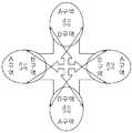
상기 PTZ카메라(150)는 패닝(Panning) 및 틸팅(Tilting)을 수행하여 촬영 방향이 피사체를 향하도록 하며, 피사체가 사람인 경우 사람의 얼굴 또는 피사체가 자동차인 경우 번호판을 중심으로 주밍(Zooming)을 수행한다. 이처럼, PTZ카메라(150)는 피사체의 정보를 식별하기 위한 구성이므로 피사체의 움직임을 감지하는 스테레오 카메라(110)보다 고해상도의 카메라를 사용하는 것이 바람직하다. 또한, PTZ카메라(150)는 스테레오 카메라(110)의 촬영 범위를 모두 커버할 수 있어야 하므로 PTZ카메라(150)와 스테레오 카메라(110)는 서로 인접하게 설치되며, 가장 바람직하게는 PTZ카메라(150)를 가운데 두고 복수의 스테레오 카메라(110)가 PTZ카메라(150)를 둘러싸는 형태가 되게 설치할 수 있다.The
여기서, 상기 PTZ카메라(150)는 구동 제어부(140)에서 산출된 구동값에 따라 제어되며, 상기 구동 제어부(140)는 PTZ카메라(150)를 구동하는 방식으로서 제1 방식과 제2 방식 중 어느 하나 또는 제1 및 제2 방식을 조합하여 PTZ카메라(150)를 구동시킨다.Here, the
도 6은 제1 방식에 의한 PTZ카메라(150)의 구동과 제2 방식에 의한 PTZ카메라(150)의 구동을 비교 설명하기 위한 도면이다.6 is a view for explaining a comparison between the driving of the
도 6을 참조하면, PTZ카메라(150)를 제어하기 위한 제1 방식은 우선 스테레오 카메라(110)의 촬영 범위 중 어느 한점의 위치를 PTZ카메라(150)의 각도와 매칭하여 초기값을 설정한다. 이후 피사체가 감지되면 피사체의 중심 좌표(예컨대 도 6의 'z')를 기초로 이동에 필요한 팬 각(θ1)과 틸트 각(θ2)을 산출하여 PTZ카메라(150)가 피사체를 향하게 하고 피사체와의 거리를 계산하여 줌 레벨을 맞춘다. 상기의 동작은 피사체가 촬영 범위에서 사라질때까지 반복될 수 있다.Referring to FIG. 6, the first method for controlling the
이러한 제1 방식은 피사체를 정확히 포착할 수 있는 장점이 있으나 연산에 필요한 데이터가 증가하기 때문에 시스템 과부하가 발생할 수 있다. 따라서 제1 방식을 보완하기 위해 제2 방식이 사용될 수 있다.Such a first method has an advantage of accurately capturing an object, but system overloading can occur due to an increase in data required for operation. Therefore, a second scheme may be used to supplement the first scheme.
PTZ카메라(150)를 제어하기 위한 제2 방식은 우선 3차원 공간에 대한 촬영 구역을 설정하고 설정된 각각의 구역(예컨대 도 6의 'a', 'b', 'c')으로 PTZ카메라(150)가 향하도록 PTZ카메라(150)의 구동값을 수동으로 프리세팅(pre-setting)한다. 이후 'a'구역에 피사체가 감지되면 'a'구역에 대한 프리세팅 값을 불러와 PTZ카메라(150)가 'a'구역의 피사체를 향하도록 구동시킨다. 'b'구역이나 'c'구역에 피사체가 감지되는 경우에도 동일하게 적용되며, 설명의 편의상 'a', 'b', 'c'구역만을 예시하였으나 촬영 대상이 되는 모든 구역에 대해 PTZ카메라(150)의 구동값을 프리세팅할 수 있다.The second method for controlling the
이상의 상세한 설명은 본 발명을 예시하는 것이다. 또한, 전술한 내용은 본 발명의 바람직한 실시 형태를 나타내고 설명하는 것에 불과하며, 본 발명은 다양한 다른 조합, 변경 및 환경에서 사용할 수 있다. 즉, 본 명세서에 개시된 발명의 개념의 범위, 저술한 개시 내용과 균등한 범위 및/또는 당업계의 기술 또는 지식의 범위 내에서 변경 또는 수정이 가능하다. 전술한 실시 예들은 본 발명을 실시하는데 있어 최선의 상태를 설명하기 위한 것이며, 본 발명과 같은 다른 발명을 이용하는데 당업계에 알려진 다른 상태로의 실시, 그리고 발명의 구체적인 적용 분야 및 용도에서 요구되는 다양한 변경도 가능하다. 따라서, 이상의 발명의 상세한 설명은 개시된 실시 상태로 본 발명을 제한하려는 의도가 아니다. 또한, 첨부된 청구범위는 다른 실시 상태도 포함하는 것으로 해석되어야 한다.The foregoing detailed description is illustrative of the present invention. In addition, the foregoing is merely illustrative and illustrative of preferred embodiments of the invention, and the invention may be used in various other combinations, modifications and environments. That is, it is possible to make changes or modifications within the scope of the concept of the invention disclosed in this specification, the disclosure and the equivalents of the disclosure and / or the scope of the art or knowledge of the present invention. The foregoing embodiments are intended to illustrate the best mode contemplated for carrying out the invention and are not intended to limit the scope of the present invention to other modes of operation known in the art for utilizing other inventions such as the present invention, Various changes are possible. Accordingly, the foregoing description of the invention is not intended to limit the invention to the precise embodiments disclosed. In addition, the appended claims should be construed to include other embodiments.
100: 다수 스테레오 카메라를 이용한 피사체 공간이동 추적 시스템
110: 스테레오 카메라120: 공간데이터 합성부
130: 피사체 감지부140: 구동 제어부
150: PTZ카메라100: Moving Object Tracking System Using Multiple Stereo Cameras
110: stereo camera 120: spatial data synthesis unit
130: object detecting unit 140:
150: PTZ camera
Claims (1)
Translated fromKorean상기 복수의 스테레오 카메라 각각의 촬영 영역에 따라 생성된 깊이지도를 정합하여 3차원 공간에 대한 정보 공유가 이루어지는 공간지도를 형성하는 공간데이터 합성부;
상기 공간지도의 포인트 클라우드를 분석하여 특정 포인트에 변화가 생기면 해당 포인트에 대응되는 스테레오 카메라의 촬영 영역에 피사체가 존재하는 것으로 판단하는 피사체 감지부;
패닝(Panning) 및 틸팅(Tilting)을 수행하여 촬영 방향이 피사체를 향하도록 이동하고 피사체를 중심으로 주밍(Zooming)을 수행하는 PTZ카메라; 및
상기 스테레오 카메라의 촬영 범위 중 어느 한점의 위치를 상기 PTZ카메라의 각도와 매칭하여 초기값을 설정하고 피사체가 감지되면 피사체의 중심 좌표를 기초로 이동에 필요한 팬 각과 틸트 각 및 피사체와의 거리에 따라 산출된 줌 레벨에 맞춰 상기 PTZ카메라를 구동하는 제1 방식과, 3차원 공간에 대한 촬영 구역을 설정하고 설정된 각각의 구역으로 촬영 방향이 향하도록 상기 PTZ카메라의 구동값을 수동으로 프리세팅(pre-setting)한 후 피사체가 감지된 구역에 대한 프리세팅 값을 호출하여 상기 PTZ카메라를 구동하는 제2 방식 중 어느 하나 또는 상기 제1 및 제2 방식의 조합에 따라 상기 PTZ카메라를 구동하는 구동 제어부;를 포함하되,
상기 스테레오 카메라는 동, 서, 남, 북 방향을 각각 촬영하는 4 개로 이루어지고,
상기 4 개의 스테레오 카메라는 서로 이격되어 설치되며 광축이 평행한 좌안렌즈와 우안렌즈를 포함하고,
상기 PTZ카메라를 가운데 두고 상기 4 개의 스테레오 카메라가 상기 PTZ카메라를 둘러싸는 형태로 설치되는 것을 특징으로 하는 다수 스테레오 카메라를 이용한 피사체 공간이동 추적 시스템.
A stereo camera composed of a plurality of units fixedly installed in different directions;
A spatial data synthesizer for mapping a depth map generated according to an imaging area of each of the plurality of stereo cameras to form a spatial map for sharing information about a three-dimensional space;
A subject sensing unit for analyzing a point cloud of the space map and determining that a subject exists in a shooting region of a stereo camera corresponding to the point when a change occurs at a specific point;
A PTZ camera that performs panning and tilting to move the photographing direction toward the subject and perform zooming around the subject; And
An initial value is set by matching the position of one of the photographing ranges of the stereo camera with the angle of the PTZ camera and when the subject is sensed, based on the center angle of the subject, the angle of the pan, tilt angle and the subject A first method of driving the PTZ camera in accordance with the calculated zoom level, a method of manually setting a driving value of the PTZ camera so as to set a photographing area for a three-dimensional space and directing the photographing direction to each zone set setting a preset value for a zone in which a subject is sensed and driving the PTZ camera, or a drive control unit for driving the PTZ camera according to a combination of the first and second modes ; ≪ / RTI >
The stereo camera is composed of four cameras for photographing the east, west, south and north directions, respectively,
The four stereo cameras include a left-eye lens and a right-eye lens which are spaced apart from each other and whose optical axes are parallel,
And the four stereo cameras are installed in the center of the PTZ camera so as to surround the PTZ camera.
Priority Applications (5)
| Application Number | Priority Date | Filing Date | Title |
|---|---|---|---|
| KR1020150174874AKR101619838B1 (en) | 2015-12-09 | 2015-12-09 | System for tracking movement of subject using multi stereo camera |
| JP2017533380AJP2018502504A (en) | 2015-12-09 | 2016-12-09 | Subject space movement tracking system using multiple stereo cameras |
| PCT/KR2016/014491WO2017099541A1 (en) | 2015-12-09 | 2016-12-09 | Subject spatial movement tracking system using multiple stereo cameras |
| US15/323,274US20180278919A1 (en) | 2015-12-09 | 2016-12-09 | System for tracking subject moving within space using stereo cameras |
| CN201680001935.9ACN107113403A (en) | 2015-12-09 | 2016-12-09 | Utilize the reference object space mobile tracing system of multiple three-dimensional cameras |
Applications Claiming Priority (1)
| Application Number | Priority Date | Filing Date | Title |
|---|---|---|---|
| KR1020150174874AKR101619838B1 (en) | 2015-12-09 | 2015-12-09 | System for tracking movement of subject using multi stereo camera |
Publications (1)
| Publication Number | Publication Date |
|---|---|
| KR101619838B1true KR101619838B1 (en) | 2016-05-13 |
Family
ID=56023655
Family Applications (1)
| Application Number | Title | Priority Date | Filing Date |
|---|---|---|---|
| KR1020150174874AActiveKR101619838B1 (en) | 2015-12-09 | 2015-12-09 | System for tracking movement of subject using multi stereo camera |
Country Status (5)
| Country | Link |
|---|---|
| US (1) | US20180278919A1 (en) |
| JP (1) | JP2018502504A (en) |
| KR (1) | KR101619838B1 (en) |
| CN (1) | CN107113403A (en) |
| WO (1) | WO2017099541A1 (en) |
Cited By (2)
| Publication number | Priority date | Publication date | Assignee | Title |
|---|---|---|---|---|
| KR101794311B1 (en) | 2017-09-11 | 2017-11-07 | 공간정보기술 주식회사 | Stereo camera system that moves the PTZ camera to the target point by projecting the GPS coordinates in 3D spatial coordinates |
| KR20180065552A (en)* | 2016-12-08 | 2018-06-18 | (주)케이아이오티 | Intelligent camera system and managing method thereof |
Families Citing this family (13)
| Publication number | Priority date | Publication date | Assignee | Title |
|---|---|---|---|---|
| CN107343174A (en)* | 2017-07-26 | 2017-11-10 | 浙江树人学院 | The false proof face iris grasp shoot device of mobile target and method at a distance |
| CN109922251B (en)* | 2017-12-12 | 2021-10-22 | 华为技术有限公司 | Method, device and system for rapid capture |
| CN108174090B (en)* | 2017-12-28 | 2020-10-16 | 北京天睿空间科技股份有限公司 | Ball machine linkage method based on three-dimensional space view port information |
| US10943485B2 (en)* | 2018-04-03 | 2021-03-09 | Baidu Usa Llc | Perception assistant for autonomous driving vehicles (ADVs) |
| CN108573456A (en)* | 2018-04-12 | 2018-09-25 | 广东汇泰龙科技有限公司 | It is a kind of based on face lock hotel self-service move in method and system |
| US11216954B2 (en)* | 2018-04-18 | 2022-01-04 | Tg-17, Inc. | Systems and methods for real-time adjustment of neural networks for autonomous tracking and localization of moving subject |
| KR101916093B1 (en) | 2018-04-20 | 2018-11-08 | 유한회사 한국케이비에프 | Method for tracking object |
| CN110460806A (en)* | 2018-05-07 | 2019-11-15 | 厦门脉视数字技术有限公司 | A kind of web camera with holder realizes the algorithm of 3D positioning and privacy screen |
| KR101996907B1 (en)* | 2018-07-27 | 2019-07-08 | 비티에스 유한회사 | Apparatus for tracking object |
| KR102537784B1 (en)* | 2018-08-17 | 2023-05-30 | 삼성전자주식회사 | Electronic device and control method thereof |
| CN110874926A (en)* | 2018-08-31 | 2020-03-10 | 百度在线网络技术(北京)有限公司 | Intelligent road side unit |
| JP2021052293A (en)* | 2019-09-24 | 2021-04-01 | ソニー株式会社 | Information processing device, information processing method, and information processing program |
| US12368823B2 (en)* | 2023-01-03 | 2025-07-22 | Adeia Guides Inc. | Systems and methods for traversing virtual spaces |
Family Cites Families (21)
| Publication number | Priority date | Publication date | Assignee | Title |
|---|---|---|---|---|
| JP3419213B2 (en)* | 1996-08-30 | 2003-06-23 | ミノルタ株式会社 | 3D shape data processing device |
| JP2000261787A (en)* | 1999-03-04 | 2000-09-22 | Matsushita Electric Ind Co Ltd | Intruding object detection method and device |
| JP4043416B2 (en)* | 2003-07-30 | 2008-02-06 | オリンパス株式会社 | Safe movement support device |
| US7667730B2 (en)* | 2005-06-15 | 2010-02-23 | Mitsubishi Electric Research Laboratories, Inc. | Composite surveillance camera system |
| JP2007085745A (en)* | 2005-09-20 | 2007-04-05 | Fuji Heavy Ind Ltd | Object monitoring device |
| JP2010015258A (en)* | 2008-07-01 | 2010-01-21 | Sony Corp | Monitoring system, information processing apparatus, information processing method, and program |
| JP2010256534A (en)* | 2009-04-23 | 2010-11-11 | Fujifilm Corp | Head-mounted display device for omnidirectional image display |
| KR101120131B1 (en)* | 2009-05-29 | 2012-03-22 | 주식회사 영국전자 | Intelligent Panorama Camera, Circuit and Method for Controlling thereof, and Video Monitoring System |
| JP5258722B2 (en)* | 2009-09-24 | 2013-08-07 | 富士フイルム株式会社 | Compound eye camera and control method thereof |
| CN102714711A (en)* | 2010-02-01 | 2012-10-03 | (株)荣国电子 | Tracking and monitoring camera device and remote monitoring system using same |
| JP2012198802A (en)* | 2011-03-22 | 2012-10-18 | Denso Corp | Intrusion object detection system |
| KR101228341B1 (en)* | 2011-04-19 | 2013-01-31 | 삼성테크윈 주식회사 | Visual survailance system and method based on cooperation between cameras |
| JP2013093013A (en)* | 2011-10-06 | 2013-05-16 | Ricoh Co Ltd | Image processing device and vehicle |
| US9749594B2 (en)* | 2011-12-22 | 2017-08-29 | Pelco, Inc. | Transformation between image and map coordinates |
| KR20140036824A (en)* | 2012-09-18 | 2014-03-26 | 삼성테크윈 주식회사 | Monitoring apparatus and system using 3d images, and method thereof |
| KR101452342B1 (en)* | 2013-04-04 | 2014-10-23 | 주식회사 이오씨 | Surveillance Camera Unit And Method of Operating The Same |
| US9742974B2 (en)* | 2013-08-10 | 2017-08-22 | Hai Yu | Local positioning and motion estimation based camera viewing system and methods |
| KR102105189B1 (en)* | 2013-10-31 | 2020-05-29 | 한국전자통신연구원 | Apparatus and Method for Selecting Multi-Camera Dynamically to Track Interested Object |
| KR101421700B1 (en)* | 2013-11-01 | 2014-07-22 | 주식회사 휴먼시스템 | real-time location trace system using intelligent analysis function of cctv and location trace method thereof |
| CN104333747B (en)* | 2014-11-28 | 2017-01-18 | 广东欧珀移动通信有限公司 | Stereoscopic photographing method and stereoscopic photographing equipment |
| CN104777835A (en)* | 2015-03-11 | 2015-07-15 | 武汉汉迪机器人科技有限公司 | Omni-directional automatic forklift and 3D stereoscopic vision navigating and positioning method |
- 2015
- 2015-12-09KRKR1020150174874Apatent/KR101619838B1/enactiveActive
- 2016
- 2016-12-09WOPCT/KR2016/014491patent/WO2017099541A1/ennot_activeCeased
- 2016-12-09JPJP2017533380Apatent/JP2018502504A/enactivePending
- 2016-12-09USUS15/323,274patent/US20180278919A1/ennot_activeAbandoned
- 2016-12-09CNCN201680001935.9Apatent/CN107113403A/enactivePending
Cited By (2)
| Publication number | Priority date | Publication date | Assignee | Title |
|---|---|---|---|---|
| KR20180065552A (en)* | 2016-12-08 | 2018-06-18 | (주)케이아이오티 | Intelligent camera system and managing method thereof |
| KR101794311B1 (en) | 2017-09-11 | 2017-11-07 | 공간정보기술 주식회사 | Stereo camera system that moves the PTZ camera to the target point by projecting the GPS coordinates in 3D spatial coordinates |
Also Published As
| Publication number | Publication date |
|---|---|
| CN107113403A (en) | 2017-08-29 |
| JP2018502504A (en) | 2018-01-25 |
| US20180278919A1 (en) | 2018-09-27 |
| WO2017099541A8 (en) | 2017-07-27 |
| WO2017099541A1 (en) | 2017-06-15 |
Similar Documents
| Publication | Publication Date | Title |
|---|---|---|
| KR101619838B1 (en) | System for tracking movement of subject using multi stereo camera | |
| US11756307B2 (en) | Vehicle video system | |
| US20170094227A1 (en) | Three-dimensional spatial-awareness vision system | |
| US10237478B2 (en) | System and method for correlating camera views | |
| US10491886B2 (en) | Virtual reality display | |
| TWI580273B (en) | Surveillance system | |
| EP2913796B1 (en) | Method of generating panorama views on a mobile mapping system | |
| KR101149329B1 (en) | Active object tracking device by using monitor camera and method | |
| US20160125585A1 (en) | Camera system and image registration method thereof | |
| CN105245850A (en) | Method, device and system for tracking objects across surveillance cameras | |
| KR101530255B1 (en) | Cctv system having auto tracking function of moving target | |
| CN102907105A (en) | Video camera providing videos with perceived depth | |
| KR101778744B1 (en) | Monitoring system through synthesis of multiple camera inputs | |
| KR102335167B1 (en) | Image photographing apparatus and method for photographing thereof | |
| US9906769B1 (en) | Methods and apparatus for collaborative multi-view augmented reality video | |
| US20150029332A1 (en) | Controlling movement of a camera to autonomously track a mobile object | |
| KR101297294B1 (en) | Map gui system for camera control | |
| CN104378622A (en) | Method and apparatus for detecting posture of surveillance camera | |
| JP5085230B2 (en) | Mobile system | |
| US20200128188A1 (en) | Image pickup device and image pickup system | |
| KR101452342B1 (en) | Surveillance Camera Unit And Method of Operating The Same | |
| EP4095745B1 (en) | An image processor and a method therein for providing a target image | |
| US10708493B2 (en) | Panoramic video | |
| JP2018139052A (en) | Communication terminal, image communication system, display method and program | |
| KR101738514B1 (en) | Monitoring system employing fish-eye thermal imaging camera and monitoring method using the same |
Legal Events
| Date | Code | Title | Description |
|---|---|---|---|
| PA0109 | Patent application | Patent event code:PA01091R01D Comment text:Patent Application Patent event date:20151209 | |
| PA0201 | Request for examination | ||
| PA0302 | Request for accelerated examination | Patent event date:20151211 Patent event code:PA03022R01D Comment text:Request for Accelerated Examination Patent event date:20151209 Patent event code:PA03021R01I Comment text:Patent Application | |
| PE0902 | Notice of grounds for rejection | Comment text:Notification of reason for refusal Patent event date:20160125 Patent event code:PE09021S01D | |
| E701 | Decision to grant or registration of patent right | ||
| PE0701 | Decision of registration | Patent event code:PE07011S01D Comment text:Decision to Grant Registration Patent event date:20160422 | |
| GRNT | Written decision to grant | ||
| PR0701 | Registration of establishment | Comment text:Registration of Establishment Patent event date:20160503 Patent event code:PR07011E01D | |
| PR1002 | Payment of registration fee | Payment date:20160504 End annual number:3 Start annual number:1 | |
| PG1601 | Publication of registration | ||
| FPAY | Annual fee payment | Payment date:20190429 Year of fee payment:4 | |
| PR1001 | Payment of annual fee | Payment date:20190429 Start annual number:4 End annual number:4 | |
| PR1001 | Payment of annual fee | Payment date:20200525 Start annual number:5 End annual number:5 | |
| PR1001 | Payment of annual fee | Payment date:20220428 Start annual number:7 End annual number:7 | |
| PR1001 | Payment of annual fee | Payment date:20230502 Start annual number:8 End annual number:8 | |
| PR1001 | Payment of annual fee | Payment date:20240502 Start annual number:9 End annual number:9 | |
| PR1001 | Payment of annual fee | Payment date:20250401 Start annual number:10 End annual number:10 |