KR101617018B1 - Low frequency curing apparatus - Google Patents
Low frequency curing apparatusDownload PDFInfo
- Publication number
- KR101617018B1 KR101617018B1KR1020150027076AKR20150027076AKR101617018B1KR 101617018 B1KR101617018 B1KR 101617018B1KR 1020150027076 AKR1020150027076 AKR 1020150027076AKR 20150027076 AKR20150027076 AKR 20150027076AKR 101617018 B1KR101617018 B1KR 101617018B1
- Authority
- KR
- South Korea
- Prior art keywords
- electrode pad
- low frequency
- electrode
- pad
- wavelength
- Prior art date
- Legal status (The legal status is an assumption and is not a legal conclusion. Google has not performed a legal analysis and makes no representation as to the accuracy of the status listed.)
- Expired - Fee Related
Links
Images


Classifications
- A—HUMAN NECESSITIES
- A61—MEDICAL OR VETERINARY SCIENCE; HYGIENE
- A61N—ELECTROTHERAPY; MAGNETOTHERAPY; RADIATION THERAPY; ULTRASOUND THERAPY
- A61N1/00—Electrotherapy; Circuits therefor
- A61N1/02—Details
- A61N1/04—Electrodes
- A61N1/0404—Electrodes for external use
- A—HUMAN NECESSITIES
- A61—MEDICAL OR VETERINARY SCIENCE; HYGIENE
- A61N—ELECTROTHERAPY; MAGNETOTHERAPY; RADIATION THERAPY; ULTRASOUND THERAPY
- A61N1/00—Electrotherapy; Circuits therefor
- A61N1/18—Applying electric currents by contact electrodes
- A61N1/32—Applying electric currents by contact electrodes alternating or intermittent currents
- A61N1/36—Applying electric currents by contact electrodes alternating or intermittent currents for stimulation
- A61N1/36014—External stimulators, e.g. with patch electrodes
- A—HUMAN NECESSITIES
- A61—MEDICAL OR VETERINARY SCIENCE; HYGIENE
- A61F—FILTERS IMPLANTABLE INTO BLOOD VESSELS; PROSTHESES; DEVICES PROVIDING PATENCY TO, OR PREVENTING COLLAPSING OF, TUBULAR STRUCTURES OF THE BODY, e.g. STENTS; ORTHOPAEDIC, NURSING OR CONTRACEPTIVE DEVICES; FOMENTATION; TREATMENT OR PROTECTION OF EYES OR EARS; BANDAGES, DRESSINGS OR ABSORBENT PADS; FIRST-AID KITS
- A61F7/00—Heating or cooling appliances for medical or therapeutic treatment of the human body
- A61F7/007—Heating or cooling appliances for medical or therapeutic treatment of the human body characterised by electric heating
- A—HUMAN NECESSITIES
- A61—MEDICAL OR VETERINARY SCIENCE; HYGIENE
- A61F—FILTERS IMPLANTABLE INTO BLOOD VESSELS; PROSTHESES; DEVICES PROVIDING PATENCY TO, OR PREVENTING COLLAPSING OF, TUBULAR STRUCTURES OF THE BODY, e.g. STENTS; ORTHOPAEDIC, NURSING OR CONTRACEPTIVE DEVICES; FOMENTATION; TREATMENT OR PROTECTION OF EYES OR EARS; BANDAGES, DRESSINGS OR ABSORBENT PADS; FIRST-AID KITS
- A61F7/00—Heating or cooling appliances for medical or therapeutic treatment of the human body
- A61F7/08—Warming pads, pans or mats; Hot-water bottles
- A—HUMAN NECESSITIES
- A61—MEDICAL OR VETERINARY SCIENCE; HYGIENE
- A61N—ELECTROTHERAPY; MAGNETOTHERAPY; RADIATION THERAPY; ULTRASOUND THERAPY
- A61N1/00—Electrotherapy; Circuits therefor
- A61N1/02—Details
- A61N1/04—Electrodes
- A61N1/0404—Electrodes for external use
- A61N1/0408—Use-related aspects
- A61N1/0452—Specially adapted for transcutaneous muscle stimulation [TMS]
- A—HUMAN NECESSITIES
- A61—MEDICAL OR VETERINARY SCIENCE; HYGIENE
- A61N—ELECTROTHERAPY; MAGNETOTHERAPY; RADIATION THERAPY; ULTRASOUND THERAPY
- A61N1/00—Electrotherapy; Circuits therefor
- A61N1/18—Applying electric currents by contact electrodes
- A61N1/32—Applying electric currents by contact electrodes alternating or intermittent currents
- A61N1/36—Applying electric currents by contact electrodes alternating or intermittent currents for stimulation
- A61N1/36014—External stimulators, e.g. with patch electrodes
- A61N1/36021—External stimulators, e.g. with patch electrodes for treatment of pain
- A—HUMAN NECESSITIES
- A61—MEDICAL OR VETERINARY SCIENCE; HYGIENE
- A61N—ELECTROTHERAPY; MAGNETOTHERAPY; RADIATION THERAPY; ULTRASOUND THERAPY
- A61N1/00—Electrotherapy; Circuits therefor
- A61N1/18—Applying electric currents by contact electrodes
- A61N1/32—Applying electric currents by contact electrodes alternating or intermittent currents
- A61N1/36—Applying electric currents by contact electrodes alternating or intermittent currents for stimulation
- A61N1/36014—External stimulators, e.g. with patch electrodes
- A61N1/3603—Control systems
- A—HUMAN NECESSITIES
- A61—MEDICAL OR VETERINARY SCIENCE; HYGIENE
- A61F—FILTERS IMPLANTABLE INTO BLOOD VESSELS; PROSTHESES; DEVICES PROVIDING PATENCY TO, OR PREVENTING COLLAPSING OF, TUBULAR STRUCTURES OF THE BODY, e.g. STENTS; ORTHOPAEDIC, NURSING OR CONTRACEPTIVE DEVICES; FOMENTATION; TREATMENT OR PROTECTION OF EYES OR EARS; BANDAGES, DRESSINGS OR ABSORBENT PADS; FIRST-AID KITS
- A61F7/00—Heating or cooling appliances for medical or therapeutic treatment of the human body
- A61F7/007—Heating or cooling appliances for medical or therapeutic treatment of the human body characterised by electric heating
- A61F2007/0071—Heating or cooling appliances for medical or therapeutic treatment of the human body characterised by electric heating using a resistor, e.g. near the spot to be heated
Landscapes
- Health & Medical Sciences (AREA)
- Life Sciences & Earth Sciences (AREA)
- Animal Behavior & Ethology (AREA)
- Engineering & Computer Science (AREA)
- Biomedical Technology (AREA)
- General Health & Medical Sciences (AREA)
- Public Health (AREA)
- Veterinary Medicine (AREA)
- Heart & Thoracic Surgery (AREA)
- Nuclear Medicine, Radiotherapy & Molecular Imaging (AREA)
- Radiology & Medical Imaging (AREA)
- Biophysics (AREA)
- Vascular Medicine (AREA)
- Pain & Pain Management (AREA)
- Electrotherapy Devices (AREA)
Abstract
Translated fromKoreanDescription
Translated fromKorean본 발명은 혈액순환의 개선과 근육통증 완화 및 근육수축에 의한 마사지효과를 얻을 수 있는 저주파 치료기에 관한 것이다.
The present invention relates to a low-frequency therapeutic apparatus capable of improving blood circulation, relieving muscle pain, and obtaining a massage effect by muscle contraction.
인체의 피로회복 증진과 피부미용, 또는 신경마비, 결림, 통증 등의 치료를 위한 마사지 장치는 크게 진동형과 저주파형이 있다.Massage devices for improving the body's fatigue recovery and skin beauty, or treating nerve palsy, stiffness, pain, etc. are largely vibrational type and low frequency type.
진동형 마사지장치는 소형 진동모터 또는 압전세라믹 진동자가 내설된 마사지 프로브에 의해 생성된 미세진동 또는 초음파가 프로부와 접촉하는 피부 부위를 초당 수십 ~ 수백만번까지 진동하여 피부 표면 및 인체 내부조직을 자극하여 피부 및 조직의 혈액 순환을 원활하게 하고 건강을 증진시키는 기능을 한다.The vibration type massage device vibrates the skin area where the micro vibration or the ultrasonic wave generated by the massage probe with the small vibration motor or the piezoelectric ceramic vibrator touches the pro part to tens to millions of times per second to stimulate the skin surface and internal tissues of the human body It functions to smooth blood circulation of skin and tissues and improve health.
저주파형 마사지장치는 인체에 접착되어 저주파 펄스 신호를 전달하는 접착패드와, 이 접착패드에 저주파 펄스 신호를 전달할 수 있도록 리드선을 통하여 연결되어 저주파 펄스를 발생시키는 저주파 발생기로 이루어진다.The low frequency type massaging device comprises an adhesive pad bonded to a human body and transmitting a low frequency pulse signal and a low frequency generator connected to the adhesive pad through a lead wire so as to transmit a low frequency pulse signal.
저주파를 이용한 전기치료는 경피적 전기신경자극, 간섭파 치료, 전기자극 치료, 신경근육 전기자극이 있다.Low frequency electrical therapy includes percutaneous electrical nerve stimulation, interfering wave therapy, electrical stimulation therapy, and neuromuscular electrical stimulation.
이러한 전기치료는 직접적으로는 근육의 생리적 활동회복과 혈액의 순환을 촉진시키며, 간접적으로는 조직에 열을 발생시켜 이에 따라 혈류량증진, 신진대사 증가, 통증 및 근경축 완화, 살균효과, 골치유 등의 효과가 있으며, 또한 전기자극이 피부에 인가되면 피부대사활동을 높여서 불필요한 노폐물이 잘 빠져나가도록 도와주고, 피하조직을 활성화시켜 세포재생과 미세혈관의 강화로 탄력있는 피부를 유지시키는 기능을 한다.This electrotherapy directly promotes recovery of physiological activity of the muscles and circulation of the blood and indirectly generates heat to the tissues, thereby increasing blood flow, increasing metabolism, relieving pain and muscular contraction, sterilization effect, , And when electric stimulation is applied to the skin, it enhances skin metabolism activity, helps unnecessary waste to escape well, activates subcutaneous tissues, and regenerates cells and strengthens microvascular tissues to maintain elastic skin .
종래 저주파형 마사지장치로서 전기요법 치료기는, 전자파를 발생시키기 위한 발진기와, 이 발진기에 접속된 도전자로 구성되며, 발진기에 접속된 도전자는 유연성을 갖는 케이스의 하부에 개구를 형성하는 동시에, 케이스 상부에 전극을 배설하고, 이 전극의 직하방 위치에 흡수성을 갖는 전극패드를 배설하며, 도전자에 흡입펌프를 관통연결한 것이 알려져 있다.Conventionally, a conventional low-frequency type massage device includes an oscillator for generating electromagnetic waves and a conductor connected to the oscillator. The conductor connected to the oscillator forms an opening in a lower portion of the flexible case, And an electrode pad having absorbency is disposed at a position directly under the electrode, and a suction pump is connected to the electrode through a conductive pipe.
또, 상기 전기요법 치료기를 이용하여 치료를 하는 경우에는, 전극패드에 수분을 흡수시킨 상태로 환부에 도전자를 장착하고 흡입펌프를 작동시킴으로써, 케이스 내의 공기를 흡입하여 도전자를 환부에 밀착시키도록 되어 있다.In addition, in the case of treatment using the above-described electrophysiotherapy apparatus, a conductive member is attached to the affected part in a state of absorbing moisture in the electrode pad, and the suction pump is operated to suck air in the case to adhere the conductive part to the affected part have.
그러나, 상기한 종래의 전기요법 치료기는 흡입펌프로써 케이스 내의 공기를 흡입하여 도전자를 환부에 밀착시키고 있으므로, 흡입펌프가 케이스 내의 공기와 함께 전극패드에 흡수된 수분까지도 흡입해 버려, 장시간 연속으로 사용하면 전극패드 내의 수분이 대량 흡입되어 전극패드가 건조해지고 통전감(痛電感)이 악화되는 동시에, 도전자와 환부의 밀착성이 저하되어 도전자가 환부에서 떨어져 버린다는 단점이 있었다.However, since the conventional electrophysiotherapy device sucks the air in the case by sucking the air in the case and adheres the conductive agent to the affected part, the suction pump sucks moisture absorbed by the electrode pad together with the air in the case, A large amount of water is sucked in the lower electrode pad, the electrode pad is dried, the electrification sensation is deteriorated, and the adhesion between the conductive part and the affected part is lowered, so that the conductive part is separated from the affected part.
이를 해결하기 위해 특허공개 제2001-0042962호가 게시되었다. 상기 특허공개 제2001-0042962호는 온수순환기를 구비하여 냉수 또는 온수를 도전자의 내부로 순환시키도록 하여 전기치료는 물론 온수에 의한 온열효과를 볼 수 있도록 한 기술이다.To solve this problem, Patent Publication No. 2001-0042962 is published. The above-mentioned Patent Publication No. 2001-0042962 has a hot water circulator and circulates the cold water or hot water to the inside of the electric conductor, so that it is possible to see the effect of heating by hot water as well as electric treatment.
그러나 상기 기술은 혹여 도전자가 환부에 긴밀히 밀착되지 않거나 떨어진 경우 온수가 외부로 배출될 수 있는 사용상의 문제가 있고, 사용자 혼자 사용하기에는 어려움이 있어 사용상 편의성이 좋지는 않은 문제점이 있었다.
However, the above-described technique has a problem in that the hot water can be discharged to the outside when the challenger is not closely attached to the affected part, or is difficult to use by the user alone.
본 발명은 상기한 문제점을 해결하기 위하여 창안된 것으로, 본 발명의 목적은 전극패드 내부에 냉수 또는 온수를 수용시킴으로써 전기치료와 함께 찜질효과를 함께 볼 수 있어 치료효과를 향상시킬 수 있으며, 환부에 흡착방식이 아닌 접촉방식으로 전기치료를 함으로써 사용자 혼자서도 스스로 손쉽게 사용할 수 있는 저주파 치료기를 제공하는 데 있다.The object of the present invention is to solve the above-mentioned problems, and it is an object of the present invention to provide a method and a device for treating cold water or hot water in an electrode pad, Frequency therapy device that can be easily used by the user himself or herself by performing electrical treatment in a contact manner rather than an adsorption method.
또한, 전기의 세기 조절은 물론 파장조절을 통해 사용자에게 적합 또는 사용자에게 불편하지 않은 주파수 및 파장으로 전기자극을 주어 치료할 수 있는 저주파 치료기를 제공하는 데 있다.It is another object of the present invention to provide a low-frequency therapy apparatus capable of treating an electric stimulation with a frequency and a wavelength that are not inconvenient to a user or a user through wavelength adjustment as well as electric power control.
또한, 간단한 구조는 물론, 소형화를 통해 가정에서도 쉽게 사용할 수 있으며, 전극패드 받침대가 구비됨으로써 등 또는 허리와 같이 사용자의 손이 닿지 않은 부위는 전극패드를 삽입 안착시켜 놓은 채 누워 사용할 수 있어 편리하게 전기치료를 할 수 있는 저주파 치료기를 제공하는 데 있다.
In addition, since the electrode pad can be easily used at home through the miniaturization as well as the simple structure, the electrode pad can be laid and used while the electrode pad is inserted and held in the area where the user's hands are not touching, And to provide a low-frequency therapy device capable of performing electric therapy.
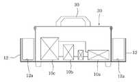
상기의 목적을 달성하기 위한 본 발명의 구성은, 저주파출력단자(11)가 일측에 구비되고 양측벽에 각각 전극패드(30)를 수용하기 위한 패드수용부(12)가 형성된 저주파발진기(10)와, 상기 저주파출력단자(11)에 일단이 끼워지고, 타단은 양극선과 음극선으로 나뉘어져 있는 저주파출력선(20)과, 상기 패드수용부(12)에 각각 수용되고 사용시 상기 저주파출력선(20)의 양극선과 음극선에 각각 하나씩 연결되는 도전성 재질로 이루어진 전극패드(30)와, 상기 전극패드(30)의 내부에 냉수 또는 온수의 수용을 위해 형성된 수용공간(40) 및 그 수용공간(40)에 물의 유입과 유출을 위해 각각의 전극패드(30)의 일측에 설치된 캡(45)과, 상기 전극패드(30)가 상측에서 삽입 안착되도록 안착홈(51)이 2개 이상 형성된 전극패드 받침대(50)를 포함하여 구성되고, 상기 수용공간(40)에 수용되는 냉수 또는 온수에 의해 상기 전극패드(30)가 냉열 또는 온열 찜질기능을 제공하는 것을 특징으로 한다.A
상기 저주파발진기(10)에는 전원공급수단으로부터 공급되는 전원의 온오프를 위한 전원스위치(13)가 설치되고, 공급전원의 전기세기를 조절하기 위한 전기조절부(14)가 설치되며, 출력되는 저주파의 파장조절을 위한 파장조절부(15)가 설치된 것을 특징으로 한다.The
상기 전기조절부(14)는 사전에 설정된 강약 두가지의 세기로 출력전기의 세기를 선택하기 위한 강약선택버튼(14a)과, 상기 강약선택버튼(14a)의 강약 중 어느 하나의 전기세기에서 사전에 설정된 수치간격으로 세밀한 전기세기 조절을 위한 다이얼버튼(14b)을 포함하여 구성된 것을 특징으로 한다.The
상기 파장조절부(15)는, 일측이 상기 저주파발진기(10)의 외부로 돌출되어 손잡이가 구비되고 파장조절을 위해 회전되게 설치되는 파장조절핀(15a)과, 그 파장조절핀(15a)의 타측에 전하의 이동이 가능하도록 근접되게 설치되고 상기 파장조절핀(15a)의 회전에 따라 파장조절핀의 타측단부에 접촉 또는 이격된 채로 떨림동작하여 저주파발생부(10b)와 그 떨림간격마다 접촉되면서 전하를 이동시키는 연결전극(15b)으로 구성된 것을 특징으로 한다.The
상기 저주파발진기(10)에는 출력되는 저주파의 파장 시간간격과 동일한 시간간격으로 점멸되는 파장확인램프(15c)가 설치되는 것을 특징으로 한다.The low frequency oscillator (10) is provided with a wavelength check lamp (15c) which is flickered at a time interval equal to the wavelength time interval of the low frequency output.
상기 패드수용부(12)의 내표면이나 바닥면에는 전극패드(30)의 수용과정에서 발생되는 충격을 흡수하도록 충격흡수재(12a)가 설치된 것을 특징으로 한다.And a
상기 전극패드(30)는, 내부에 수용공간(40)이 형성된 도전성 재질의 원형 또는 다각형 통체로 된 도전체(31)와, 상기 도전체(31)의 일면에 씌워져 결합수단(33)으로 결합되고 수분을 흡수한 채로 환부에 밀착되는 흡습부재(32)와, 상기 흡습부재(32)가 씌워지지 않은 나머지 부분을 커버하고 외측면에 걸림돌기(34a)가 다수 형성된 절연재질의 패드커버(34)로 구성된 것을 특징으로 한다.The
상기 저주파발진기(10)에는 전원공급수단으로부터 공급되는 전원을 외부로 출력하는 전원출력단자(16)가 설치되고, 상기 전극패드(30)의 일측에는 상기 수용공간(40)의 내부로 인입되어 내부에 수용된 온수를 가열하도록 발열체(60)가 설치되며, 상기 발열체(60)는 상기 전원출력단자(16)에 전원선(17)으로 연결되어 전원을 공급받는 것을 특징으로 한다.The
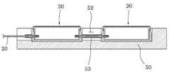
상기 전극패드 받침대(50)에 형성된 안착홈(51)은 2의 배수로 다수 개 형성되고, 상기 전극패드 받침대(50)의 상면에는 인접되는 안착홈(51)과 연통되게 일정 깊이로 잭삽입홈(52)이 형성되고, 그 잭삽입홈(52)에는 인접되는 안착홈(51)에 삽입 안착되는 전극패드를 상호 연결하도록 연결잭(53)이 삽입되게 마련되며, 상기 연결잭(53)으로 연결되는 전극패드 중 양극선에 연결되는 전극패드는 양극선에만 연결되고, 음극선에 연결되는 전극패드는 음극선에만 연결되는 것을 특징으로 한다.
A plurality of
상기의 구성으로 이루어진 저주파 치료기에 따르면, 전기치료에 따른 혈액순환의 개선과 근육통증을 완화시킬 수 있음은 물론 근육수축에 의한 마사지효과를 기대할 수 있고, 전기치료와 함께 냉수 또는 온수에 의한 찜질(냉,온)효과를 동시에 얻을 수 있어 치료효과를 향상시킬 수 있으며, 사용자 혼자 스스로도 손쉽게 취급할 수 있어 사용상 편의성이 좋은 효과가 있다.
According to the low-frequency treatment device having the above-described configuration, it is possible to improve the blood circulation and relieve the muscle pain by the electric therapy, and to expect the massage effect by the muscle contraction. In addition, Cooling, and warming effect can be obtained at the same time, so that the treatment effect can be improved, and the user can easily handle the treatment by himself / herself.
도 1은 본 발명에 따른 저주파 치료기의 사시도,
도 2는 본 발명에 따른 패드수용부에 전극패드가 수용된 상태의 저주파발진기를 보인 사시도,
도 3은 본 발명에 따른 저주파발진기의 단면상태도,
도 4는 본 발명에 다른 저주파치료기에서 파장조절부를 보인 발췌도,
도 5는 본 발명에 따른 전극패드의 단면상태도,
도 6은 본 발명에 따른 전극패드 받침대에 안착되는 전극패드의 설치상태도,
도 7은 본 발명에 따른 전극패드가 안착된 전극패드 받침대의 단면상태도,
도 8은 본 발명에 따른 다이얼버튼 근방에 부착되는 안내표지를 보인 상태도,
도 9는 본 발명에 따른 저주파발진기와 전극패드의 연결을 보인 블록도,
도 10은 본 발명에 따른 전원선에 연결되는 발열체를 보인 전극패드의 단면상태도.1 is a perspective view of a low-frequency therapy apparatus according to the present invention,
FIG. 2 is a perspective view showing a low-frequency oscillator in which an electrode pad is housed in a pad accommodating portion according to the present invention;
3 is a cross-sectional view of a low-frequency oscillator according to the present invention.
4 is an excerpt showing a wavelength adjusting unit in the low-frequency treatment apparatus according to the present invention,
5 is a cross-sectional view of an electrode pad according to the present invention,
6 is an installation view of an electrode pad that is seated on the electrode pad support according to the present invention.
FIG. 7 is a cross-sectional view of an electrode pad pedestal having an electrode pad according to the present invention,
8 is a state diagram showing a guide marker attached near the dial button according to the present invention,
9 is a block diagram showing a connection between a low-frequency oscillator and an electrode pad according to the present invention.
10 is a cross-sectional view of an electrode pad showing a heating element connected to a power line according to the present invention.
이하, 첨부된 도면을 참조하여 본 발명의 바람직한 실시예에 따른 저주파 치료기를 상세히 설명하기로 한다.Hereinafter, a low-frequency apparatus according to a preferred embodiment of the present invention will be described in detail with reference to the accompanying drawings.
도 1은 본 발명에 따른 저주파 치료기의 사시도이고, 도 2는 본 발명에 따른 패드수용부에 전극패드가 수용된 상태의 저주파발진기를 보인 사시도이며, 도 3은 본 발명에 따른 저주파발진기의 단면상태도이고, 도 4는 본 발명에 다른 저주파치료기에서 파장조절부를 보인 발췌도이며, 도 5는 본 발명에 따른 전극패드의 단면상태도이며, 도 6은 본 발명에 따른 전극패드 받침대에 안착되는 전극패드의 설치상태도이고, 도 7은 본 발명에 따른 전극패드가 안착된 전극패드 받침대의 단면상태도이며, 도 8은 본 발명에 따른 다이얼버튼 근방에 부착되는 안내표지를 보인 상태도이고, 도 9는 본 발명에 따른 저주파발진기와 전극패드의 연결을 보인 블록도이며, 도 10은 본 발명에 따른 전원선에 연결되는 발열체를 보인 전극패드의 단면상태도이다.2 is a perspective view showing a low-frequency oscillator in a state where an electrode pad is received in a pad accommodating portion according to the present invention. FIG. 3 is a sectional view of a low-frequency oscillator according to the present invention. 5 is a sectional view of an electrode pad according to the present invention. FIG. 6 is a cross-sectional view of the electrode pad according to the present invention. FIG. 7 is a cross-sectional view of the electrode pad support with the electrode pad according to the present invention, FIG. 8 is a view showing a guide mark attached to the vicinity of the dial button according to the present invention, and FIG. 10 is a cross-sectional view of an electrode pad having a heating element connected to a power line according to the present invention. FIG. 10 is a cross-sectional view illustrating a connection between a low-frequency oscillator and an electrode pad.
상기 도면에 도시된 바와 같이, 본 발명에 따른 저주파 치료기는 저주파를 발생시키도록 구성된 저주파발진기(10)와, 상기 저주파발진기(10)에 저주파출력선(20)으로 연결되는 도전성 재질의 전극패드(30)와, 냉수 또는 온수의 수용을 위한 수용공간(40) 및 캡(45)과, 전극패드를 받쳐주기 위한 전극패드 받침대(50)를 포함하여 이루어진다.The low-frequency electric therapy apparatus according to the present invention comprises a low-
상기 저주파발진기(10)는 환부를 치료하기 위해 저주파를 발생시키는 장치로서, 전원공급수단(10a)이 설치되어 있고, 내부에는 저주파발생부(10b)와 출력제어부(10c)가 구비되어 있으며, 각각의 구성이 회로연결되어 발생된 저주파를 외부로 출력하도록 이루어져 있다.The low-
상기 전원공급수단(10a)은 배터리나 플러그로 구성하여 배터리의 전원이나 상용전원을 전원으로 사용하여 저주파발진기에 공급하도록 한다.The power supply means 10a is constituted by a battery or a plug, and supplies power to the low frequency oscillator by using a power source of the battery or a commercial power source as a power source.
상기 저주파발진기(10)의 일측에는 저주파의 출력을 위해 저주파출력단자(11)가 형성된다.A low
또한, 상기 저주파발진기(10)에는 상기 전극패드(30)를 보관하기 위해 전극패드가 수용되는 패드수용부(12)가 양측벽에 형성되어 있고, 정면에는 전원공급수단으로부터 공급되는 전원의 온오프를 위한 전원스위치(13)가 설치되고, 공급전원의 전기세기를 조절하기 위한 전기조절부(14)가 설치되며, 출력되는 저주파의 파장간격 조절을 위한 파장조절부(15)가 설치되어 있다.In the low-
상기 전기조절부(14)는 출력되는 전기를 사용자가 임의로 조절하기 위한 것으로, 사용자 자신에 맞는 전기 세기로 조절할 수 있다.The electricity regulating
전기 세기조절은 기본적으로 강약선택을 통해 두 가지의 세기로 조절할 수 있고, 강약 선택 후 다이얼버튼을 통해 세밀한 조절이 가능하다.Electricity intensity control can be adjusted to two intensities by selecting intensity basically, and it is possible to fine-tune it through dial button after selecting intensity.
구체적으로, 상기 전기조절부(14)는 사전에 설정된 강약 두가지의 세기로 출력전기의 세기를 선택하기 위한 강약선택버튼(14a)과, 상기 강약선택버튼(14a)의 강약 중 어느 하나의 전기세기에서 세밀한 전기세기 조절을 위한 다이얼버튼(14b)을 포함하여 구성된다.Specifically, the
상기 강약선택버튼과 다이얼버튼을 통한 전기세기를 조절하는 경우, 조절되는 전기값은 사전에 이미 설정되어 있다.In the case of adjusting the electric strength through the intensity selection button and the dial button, the electric value to be adjusted is already set in advance.
예로서, 강약선택버튼을 통한 강에 해당되는 전기세기는 7~8V이고, 약에 해당되는 전기세기는 5~6V이다. 이때 전기세기가 높음에 따라 주파수도 높아짐은 당연하다.As an example, the electrical intensity corresponding to the steel through the intensity selection button is 7 ~ 8V, and the electrical intensity corresponding to the medicine is 5 ~ 6V. At this time, the higher the electric strength, the higher the frequency.
그리고, 상기 다이얼버튼의 세기는 예로서, 0.1V 간격으로 10단계로 구성할 수 있다.The intensity of the dial buttons may be, for example, 10 steps at intervals of 0.1V.
본 발명에서 다이얼버튼에는 도 7에 도시된 바와 같이, 환부부위마다 각각 다른 세기로 사용할 수 있도록 안내표지가 부착될 수 있다. 이는 사용하고자 하는 환부 부위마다 사용자가 쉽게 인지하여 세기를 조절하여 사용할 수 있도록 하여 원하는 치료효과를 얻을 수 있도록 하기 위함이다.In the present invention, as shown in FIG. 7, the dial button may be provided with a guide mark for use with different intensities for each affected area. This is to allow the user to easily perceive the portion of the affected part to be used and to adjust the intensity so that the desired therapeutic effect can be obtained.
상기 파장조절부(15)는 출력되는 저주파의 파장 간격을 조절하기 위한 것으로, 파장 간격조절을 굳이 하지 않아도 무방하나, 파장조절부를 통해 주파수의 파장 간격을 줄여주거나 늘려주어 사용자가 원하는 파장간격으로 저주파치료를 받을 수 있도록 하기 위한 것이다.The wavelength adjuster 15 adjusts the wavelength interval of the output low-frequency wave. It is not necessary to adjust the wavelength interval. However, it is possible to reduce or increase the wavelength interval of the frequency through the wavelength adjuster, So that they can receive treatment.
구체적으로, 상기 파장조절부(15)는 일측이 상기 저주파발진기(10)의 외부로 돌출되어 손잡이가 구비되고 파장 간격조절을 위해 회전되게 설치되는 파장조절핀(15a)과, 그 파장조절핀(15a)의 타측에 전하의 이동이 가능하도록 근접되게 설치되는 연결전극(15b)으로 구성된다.Specifically, the
상기 파장조절핀은 회전을 통해 연결전극과의 사이거리를 조절하여 연결전극의 떨림간격을 조정할 수 있으며, 떨림간격 조정을 통해 연결전극이 저주파발생부와에 접촉되는 간격을 조절하여 저주파의 파장간격을 조정하게 되는 것이다.The wavelength adjusting pin adjusts a distance between the connection electrode and the connection electrode by adjusting the distance between the connection electrode and the connection electrode. .
상기 연결전극은 상기 파장조절핀(15a)의 회전에 따라 파장조절핀의 타측단부에 접촉되거나 이격된 채로 떨림동작하게 되는 것이고, 저주파발생부(10b)와 그 떨림간격마다 접촉되면서 전하를 이동시키게 된다.The connection electrode is tilted while being in contact with or spaced from the other end of the wavelength tuning pin in accordance with the rotation of the
따라서, 상기 파장조절부(15)에 의해 출력되는 파장간격이 상이하게 됨으로써 근육이나 혈행의 마사지효과를 극대화시킬 수 있게 되는 것이며, 사용자에 따라 자신에게 맞는 파장간격으로 하여 저주파가 출력되도록 하여 사용하면 된다.Accordingly, since the wavelength intervals output by the
상기 연결전극이 떨림동작하면서 저주파발생부(10b)에 부딪히는 경우 소음이 발생되는데, 이러한 소음이 외부로 전달되지 않도록 상기 저주파발생부(10b)와 연결전극의 접촉부위는 차폐부재로 덮어 소음을 최소화하도록 할 수도 있다.When the connection electrode is shaken and hits the low
이때, 상기 저주파발진기(10)에는 출력되는 저주파의 파장 시간간격과 동일한 시간간격으로 점멸되는 파장확인램프(15c)가 설치된다. 상기 파장확인램프는 엘이디로 구성된 것으로서, 상기 파장조절부(15)를 통한 저주파의 파장을 조절하는 경우에 그 파장 시간간격과 동일한 간격으로 점멸되도록 하여 사용자나 주위사람이 현재 출력되는 주파수의 파장 시간간격을 육안확인할 수 있도록 하기 위한 것이다.At this time, the
그리고 상기 저주파발진기(10)에는 타이머(18)가 설치되어 저주파발진기의 동작시간을 사용자가 선택할 수 있도록 하고, 상면에는 저주파발진기를 들어 이동시킬 수 있도록 손잡이(19)가 형성되어 있다.The
상기 패드수용부(12)의 내표면이나 바닥면에는 전극패드(30)를 수용시키는 경우에 충격을 흡수하여 손상을 방지함은 물론, 소음을 줄이도록 충격흡수재(12a)가 설치된다.The
상기 저주파출력선(20)은 일단은 하나의 잭으로 구성되고, 타단이 양극선과 음극선으로 나뉘어지도록 구성된 것으로, 일단이 상기 저주파출력단자(11)에 일단이 끼워지는 것이고, 타단의 양극선과 음극선에 각각 전극패드(30)가 연결된다.One end of the low
양극선과 음극선에 하나씩 연결한 이유는 인체의 환부에 접촉시키는 경우, 인체를 통해 전기가 흐르도록 하여 치료효과를 얻기 위한 것이다.The reason for connecting the positive and negative electrodes one by one is to obtain a therapeutic effect by allowing electricity to flow through the human body when contacting the affected part of the human body.
상기 전극패드(30)는 원형 또는 다각형으로 형성될 수 있으나, 사용상의 편의를 위해 원형으로 형성하도록 한다.The
이러한 전극패드(30)는 내부에 수용공간(40)이 형성된 도전성 재질의 원형 또는 다각형 통체로 된 도전체(31)와, 상기 도전체(31)의 일면에 씌워져 결합수단(33)으로 결합되고 수분을 흡수한 채로 환부에 밀착되는 흡습부재(32)와, 상기 흡습부재(32)가 씌워지지 않은 나머지 부분을 커버하고 외측면에 걸림돌기(34a)가 다수 형성된 절연재질의 패드커버(34)로 구성되어 있다.The
상기 흡습부재(32)는 수분을 흡수하기 위한 재질로, 안쪽에서부터 솜, 부직포 또는 천을 덧대어 구성할 수 있다.The moisture absorbing member (32) is a material for absorbing moisture, and may be formed by inserting a cotton, a nonwoven fabric or a cloth from the inside.
본 발명에서 상기 흡습부재(32)는 도전체의 일면에 씌워짐에 따라 상기 결합수단(33)은 흡습부재의 가장자리를 도전체에 결속하기 위한 고무밴드로 구성할 수 있다.In the present invention, as the moisture absorption member (32) is covered on one side of the conductor, the coupling means (33) can be constituted by a rubber band for binding the edge of the moisture absorption member to the conductor.
상기 패드커버(34)는 절연을 위해 일정 두께 이상으로 형성되어야 할 것이고, 외측면에는 사용자가 전극패드를 들어 이동시키거나 든 채로 환부에 밀착시키는 경우 손에서 쉽게 미끌리지 않도록 상기 걸림돌기(34a)가 형성되어 있다.The pad cover 34 should be formed to have a predetermined thickness or more for insulation. The pad cover 34 should be formed to have a thickness larger than that of the pad cover 34. In order to prevent the pad cover 34 from being easily attracted to the user, Respectively.
상기 수용공간(40)은 상기 전극패드(30), 정확하게는 도전체의 내부에 냉수 또는 온수의 수용을 위해 형성된 공간이고, 상기 캡(45)은 수용공간(40)에 물을 유입시키거나 유출시키기 위해 각각의 전극패드(30)의 일측 정확하게는 도전체의 일측에 설치되는 것이다.The housing space 40 is a space formed for accommodating cold or hot water in the
상기 캡은 용이한 결합을 위해 도전체의 일측에 나선결합되게 설치한다.The cap is spirally connected to one side of the conductor for easy coupling.
따라서, 본 발명에서는 수용공간에 수용되는 냉수 또는 온수에 의해 상기 전극패드(30)가 냉열 또는 온열 찜질기능을 제공하게 됨으로써 저주파 치료효과는 물론, 찜질효과를 함께 제공할 수 있게 된다.Therefore, in the present invention, the
상기 전극패드 받침대(50)는 사용자가 손으로 전극패드를 들어 사용하지 못하는 환부에 밀착시키고자 하는 경우에 사용하는 것으로, 상기 전극패드(30)가 상측에서 삽입 안착되도록 상면에 안착홈(51)이 2개 이상 형성되어 있고, 딱딱하지 않은 실리콘재질이나 고무재질로 형성하도록 한다.The
이때, 상기 안착홈(51)은 2개만 형성되거나 그 이상 2의 배수로 다수 개 형성될 수 있다.At this time, only two of the
2의 배수로 4개 이상 형성된 경우, 상기 전극패드 받침대(50)의 상면에는 인접되는 안착홈(51)과 연통되게 일정 깊이로 잭삽입홈(52)이 형성되고, 그 잭삽입홈(52)에는 인접되는 안착홈(51)에 삽입 안착되는 전극패드를 상호 연결하도록 연결잭(53)이 삽입되게 마련된다.A
실시예로서, 도 6 및 도 7에 도시된 바와 같이 상기 안착홈이 4개 형성된 경우에는 일측에 형성된 2개의 안착홈에는 저주파출력선의 양극선과 음극선에 직접연결되는 전극패드가 각각 하나씩 삽입되고, 타측에 형성된 나머지 2개의 안착홈에 삽입된 전극패드는 양극선과 음극선에 각각 연결된 전극패드에 연결잭(53)으로 연결되도록 설치되는 것이고, 연결잭(53)은 잭삽입홈(52)에 삽입된 상태로 각각의 전극패드를 서로 연결한 상태를 유지하게 된다.6 and 7, when four of the seating grooves are formed, one of the two seating grooves formed at one side is inserted with a positive electrode of a low-frequency output line and one electrode pad directly connected to the cathode line, And the
여기서, 상기 연결잭(53)으로 연결되는 전극패드는 양극선과 음극선이 함께 연결되지 않도록 양극선에 연결되는 전극패드는 양극선에만 연결되고, 음극선에 연결되는 전극패드는 음극선에만 연결되도록 하는 것이 바람직하다.Here, the electrode pads connected to the
그 이유는 인체를 통해 전기가 통하도록 하여 전기치료효과를 얻기 위함이다.The reason for this is to allow electricity to pass through the body to obtain the effect of electrotherapy.
한편, 도 9 및 도 10에 도시된 바와 같이 상기 저주파발진기(10)에는 전원공급수단으로부터 공급되는 전원을 외부로 출력하는 전원출력단자(16)가 설치되고, 상기 전극패드(30)의 일측에는 상기 수용공간(40)의 내부로 인입되게 설치되어 전원출력단자에 전원선으로 연결되어 전원선을 통해 공급되는 전원으로 수용공간 내부에 수용된 온수를 가열하도록 발열체(60)가 설치될 수 있다.9 and 10, the low-
상기 발열체(60)는 온수의 온도를 일정 온도로 유지하기 위한 것으로, 최초 수용공간에 온수를 수용한 상태에서 일정 시간이 지나면 온수의 온도가 내려가 찜질효과가 낮아지게 되므로, 찜질효과를 높이기 위해 온수를 가열하여 온도를 높여주기 위함이다.In order to maintain the temperature of the hot water at a predetermined temperature, the temperature of the hot water is lowered after a certain period of time in the state where the hot water is received in the first accommodating space. As a result, So that the temperature is increased.
상기와 같이 구성된 본 발명의 저주파 치료기는 사용전에는 저주파발진기(10)의 패드수용부(12)에 전극패드(30)가 수용되어 있고, 저주파출력선(20)도 저주파출력단자(11)에서 뽑혀 연결되어 있지 않은 상태이다.The
이 상태에서 저주파 치료기를 사용하게 되면, 먼저 전극패드(30)를 패드수용부에서 인출시킨 후 캡을 개방하여 수용공간에 온수 또는 냉수를 수용시킨 다음 캡을 폐쇄하고, 저주파출력선의 일단을 저주파출력단자에 끼워 연결하고 타단의 양극선과 음극선에 각각 전극패드(30)를 하나씩 연결한다.In this state, the
이 후, 전극패드의 흡습부재(32)에 수분을 뿌리거나 묻혀 환부 또는 환부 근방에 밀착시키고, 전원스위치를 온동작시켜 저주파의 발생과 함께 저주파를 출력하여 전극패드를 통해 환부에 전달되게 하여 전기치료를 한다.Thereafter, water is sprinkled or buried in the moisture absorbing member 32 of the electrode pad so as to be brought into close contact with the vicinity of the affected part or the affected part and the power switch is turned on to generate a low frequency and transmit a low frequency to the affected part through the electrode pad, Treat it.
이때, 파장을 조절하고자 하는 경우에는 파장조절부(15)를 조절하고, 전기세기를 조절하고자 하는 경우에는 전기조절부(14)를 조절하여 원하는 세기로 출력되게 하면 된다.At this time, when the wavelength is to be adjusted, the
본 발명의 전극패드는 전기를 인체에 전달하는 기능과 찜질기능을 하게 됨으로써 전기치료효과와 찜질효과를 함께 제공받을 수 있게 된다.INDUSTRIAL APPLICABILITY According to the electrode pad of the present invention, a function of delivering electricity to a human body and a function of fomenting a body are provided, thereby providing an electric treatment effect and a fomenting effect.
전기치료를 마친 후에는 저주파발진기에서 저주파출력선을 분리하고 전극패드를 저주파출력선에서 분리하여 패드수용부(12)에 수용하여 보관하면 된다.
After the electric treatment, the low-frequency output line is separated from the low-frequency oscillator, and the electrode pad is separated from the low-frequency output line and stored in the pad accommodating portion (12).
10: 저주파발진기10a: 전원공급수단
10b: 저주파발생부10c: 출력제어부
11: 저주파출력단자12: 패드수용부
12a: 충격흡수재 13: 전원스위치
14: 전기조절부14a: 강약선택버튼
14b: 다이얼버튼15: 파장조절부
15a: 파장조절핀15b: 연결전극
15c: 파장확인램프16: 전원출력단자
17: 전원선18: 타이머
19: 손잡이20: 저주파출력선
30: 전극패드31: 도전체
32: 흡습부재33: 결합수단
34: 패드커버34a: 걸림돌기
40: 수용공간45: 캡
50: 전극패드 받침대51: 안착홈
52: 잭삽입홈53: 연결잭
60: 발열체10: Low-
10b:
11: Low frequency output terminal 12: Pad receiving portion
12a: shock absorber 13: power switch
14:
14b: Dial button 15: Wavelength control section
15a:
15c: wavelength check lamp 16: power output terminal
17: power line 18: timer
19: Handle 20: Low frequency output line
30: Electrode pad 31: Conductor
32: moisture absorbing member 33: engaging means
34: Pad cover 34a:
40: accommodation space 45: cap
50: electrode pad pedestal 51: seat groove
52: Jack insertion groove 53: Connection jack
60: Heating element
Claims (9)
Translated fromKorean상기 저주파출력단자(11)에 일단이 끼워지고, 타단은 양극선과 음극선으로 나뉘어져 있는 저주파출력선(20)과,
상기 패드수용부(12)에 각각 수용되고 사용시 상기 저주파출력선(20)의 양극선과 음극선에 각각 하나씩 연결되는 도전성 재질로 이루어진 전극패드(30)와,
상기 전극패드(30)의 내부에 냉수 또는 온수의 수용을 위해 형성된 수용공간(40) 및 그 수용공간(40)에 물의 유입과 유출을 위해 각각의 전극패드(30)의 일측에 설치된 캡(45)과,
상기 전극패드(30)가 상측에서 삽입 안착되도록 안착홈(51)이 2개 이상 형성된 전극패드 받침대(50)를 포함하여 구성되고,
상기 수용공간(40)에 수용되는 냉수 또는 온수에 의해 상기 전극패드(30)가 냉열 또는 온열 찜질기능을 제공하는 것을 특징으로 하는 저주파 치료기.
A low frequency oscillator 10 having a low frequency output terminal 11 on one side and a pad accommodating portion 12 for accommodating the electrode pad 30 on both side walls;
A low frequency output line 20 having one end inserted into the low frequency output terminal 11 and the other end divided into a positive electrode line and a negative electrode line,
An electrode pad 30 made of a conductive material, which is accommodated in the pad accommodating portion 12 and is connected to the positive and negative electrodes of the low frequency output line 20,
A cap 45 provided on one side of each of the electrode pads 30 for inflow and outflow of water into and from the accommodating space 40 formed for accommodating cold water or hot water in the electrode pad 30; )and,
And an electrode pad pedestal 50 in which two or more seating grooves 51 are formed so that the electrode pads 30 are inserted and seated from above,
Wherein the electrode pad (30) is provided with a cold or hot pad function by cold water or hot water stored in the accommodation space (40).
상기 저주파발진기(10)에는 전원공급수단으로부터 공급되는 전원의 온오프를 위한 전원스위치(13)가 설치되고, 공급전원의 전기세기를 조절하기 위한 전기조절부(14)가 설치되며, 출력되는 저주파의 파장조절을 위한 파장조절부(15)가 설치된 것을 특징으로 하는 저주파 치료기.
The method according to claim 1,
The low frequency oscillator 10 is provided with a power switch 13 for turning on and off the power supplied from the power supply means and an electric control unit 14 for adjusting the electric strength of the power supply. And a wavelength adjusting unit (15) for adjusting the wavelength of the laser beam.
상기 전기조절부(14)는 사전에 설정된 강약 두 가지의 세기로 출력전기의 세기를 선택하기 위한 강약선택버튼(14a)과, 상기 강약선택버튼(14a)의 강약 중 어느 하나의 전기 세기에서 사전에 설정된 수치간격으로 세밀한 전기의 세기조절을 위한 다이얼버튼(14b)을 포함하여 구성된 것을 특징으로 하는 저주파 치료기.
3. The method of claim 2,
The electric control unit 14 is provided with a strength selection button 14a for selecting the intensity of the output electric power at two preset strengths and a strength selection button 14b for selecting one of the intensity of the strength selection button 14a And a dial button (14b) for controlling the intensity of the electric power at a numerical interval set in the dial button (14b).
상기 파장조절부(15)는, 일측이 상기 저주파발진기(10)의 외부로 돌출되어 손잡이가 구비되고 파장 간격조절을 위해 회전되게 설치되는 파장조절핀(15a)과, 그 파장조절핀(15a)의 타측에 전하의 이동이 가능하도록 근접되게 설치되고 상기 파장조절핀(15a)의 회전에 따라 파장조절핀의 타측단부에 접촉 또는 이격된 채로 떨림동작하여 그 떨림간격마다 저주파발생부(10b)에 접촉되면서 전하를 이동시키는 연결전극(15b)으로 구성된 것을 특징으로 하는 저주파 치료기.
3. The method of claim 2,
The wavelength tuning unit 15 includes a wavelength tuning pin 15a having one side protruded to the outside of the low frequency oscillator 10 and provided with a handle and rotated to adjust a wavelength interval, And is moved in contact with or spaced from the other end of the wavelength tuning pin in accordance with the rotation of the wavelength tuning pin 15a so as to be moved to the low frequency generating portion 10b And a connection electrode (15b) for transferring the electric charge while being in contact.
상기 저주파발진기(10)에는 출력되는 저주파의 파장 시간간격과 동일한 시간간격으로 점멸되는 파장확인램프(15c)가 설치되는 것을 특징으로 하는 저주파 치료기.
3. The method of claim 2,
Wherein the low frequency oscillator (10) is provided with a wavelength check lamp (15c) which is flickered at a time interval equal to the wavelength time interval of the low frequency outputted.
상기 패드수용부(12)의 내표면이나 바닥면에는 전극패드(30)의 수용과정에서 발생되는 충격을 흡수하도록 충격흡수재(12a)가 설치된 것을 특징으로 하는 저주파 치료기.
The method according to claim 1,
Wherein a shock absorber (12a) is installed on an inner surface or a bottom surface of the pad receiving portion (12) to absorb an impact generated in the process of receiving the electrode pad (30).
상기 전극패드(30)는, 내부에 수용공간(40)이 형성된 도전성 재질의 원형 또는 다각형 통체로 된 도전체(31)와, 상기 도전체(31)의 일면에 씌워져 결합수단(33)으로 결합되고 수분을 흡수한 채로 환부에 밀착되는 흡습부재(32)와, 상기 흡습부재(32)가 씌워지지 않은 나머지 부분을 커버하고 외측면에 걸림돌기(34a)가 다수 형성된 절연재질의 패드커버(34)로 구성된 것을 특징으로 하는 저주파 치료기.
The method according to claim 1,
The electrode pad 30 includes a conductor 31 made of a circular or polygonal cylinder made of a conductive material having a receiving space 40 formed therein and a conductive member 31 covering the conductor 31, A pad cover 34 of an insulating material which covers the remaining portion not covered with the moisture absorbent member 32 and has a plurality of locking projections 34a formed on the outer surface thereof, ) Of the low-frequency electric power.
상기 저주파발진기(10)에는 전원공급수단으로부터 공급되는 전원을 외부로 출력하는 전원출력단자(16)가 설치되고, 상기 전극패드(30)의 일측에는 상기 수용공간(40)의 내부로 인입되어 내부에 수용된 온수를 가열하도록 발열체(60)가 설치되며,
상기 발열체(60)는 상기 전원출력단자(16)에 전원선(17)으로 연결되어 전원을 공급받는 것을 특징으로 하는 저주파 치료기.
The method according to claim 1,
The low frequency oscillator 10 is provided with a power output terminal 16 for outputting a power supplied from a power supply means to the outside, A heating element 60 is installed so as to heat the hot water stored in the heating element 60,
Wherein the heating element (60) is connected to the power output terminal (16) by a power line (17) to receive power.
상기 전극패드 받침대(50)에 형성된 안착홈(51)은 2의 배수로 다수 개 형성되고,
상기 전극패드 받침대(50)의 상면에는 인접되는 안착홈(51)과 연통되게 일정 깊이로 잭삽입홈(52)이 형성되고, 그 잭삽입홈(52)에는 인접되는 안착홈(51)에 삽입 안착되는 전극패드를 상호 연결하도록 연결잭(53)이 삽입되게 마련되며,
상기 연결잭(53)으로 연결되는 전극패드 중 양극선에 연결되는 전극패드는 양극선에만 연결되고, 음극선에 연결되는 전극패드는 음극선에만 연결되는 것을 특징으로 하는 저주파 치료기.The method according to claim 1,
A plurality of seating grooves (51) formed in the electrode pad pedestal (50) are formed in multiples of two,
The upper surface of the electrode pad pedestal 50 is formed with a jack insertion groove 52 having a predetermined depth so as to communicate with an adjacent seating groove 51. In the jack insertion groove 52, A connection jack 53 is inserted to connect the electrode pads to be seated,
Wherein the electrode pad connected to the anode line is connected to only the anode line among the electrode pads connected to the connection jack 53, and the electrode pad connected to the cathode line is connected to only the cathode line.
Priority Applications (1)
| Application Number | Priority Date | Filing Date | Title |
|---|---|---|---|
| KR1020150027076AKR101617018B1 (en) | 2015-02-26 | 2015-02-26 | Low frequency curing apparatus |
Applications Claiming Priority (1)
| Application Number | Priority Date | Filing Date | Title |
|---|---|---|---|
| KR1020150027076AKR101617018B1 (en) | 2015-02-26 | 2015-02-26 | Low frequency curing apparatus |
Publications (1)
| Publication Number | Publication Date |
|---|---|
| KR101617018B1true KR101617018B1 (en) | 2016-04-29 |
Family
ID=55916016
Family Applications (1)
| Application Number | Title | Priority Date | Filing Date |
|---|---|---|---|
| KR1020150027076AExpired - Fee RelatedKR101617018B1 (en) | 2015-02-26 | 2015-02-26 | Low frequency curing apparatus |
Country Status (1)
| Country | Link |
|---|---|
| KR (1) | KR101617018B1 (en) |
Cited By (5)
| Publication number | Priority date | Publication date | Assignee | Title |
|---|---|---|---|---|
| KR101882471B1 (en) | 2017-08-29 | 2018-07-27 | 조인바이 주식회사 | Muscle stimulating apparatus |
| KR20190009065A (en) | 2017-07-18 | 2019-01-28 | 주식회사 메디렉스 | Ict sponge and method of ict sponge and |
| CN111202677A (en)* | 2020-03-12 | 2020-05-29 | 王玉 | Potential copper moxibustion instrument |
| KR20220003872A (en) | 2020-07-02 | 2022-01-11 | (주)쥬비스다이어트 | A visit consulting system for stimulation exercise using low frequency heads |
| KR20250011343A (en) | 2023-07-14 | 2025-01-21 | 주식회사 지에이치엘 | Low frequency stimulator of necklace type |
Citations (5)
| Publication number | Priority date | Publication date | Assignee | Title |
|---|---|---|---|---|
| JPH06285173A (en)* | 1993-03-31 | 1994-10-11 | Matsushita Electric Works Ltd | Container for low frequency curing device |
| KR200199086Y1 (en)* | 2000-04-27 | 2000-10-02 | 조재희 | Hot pack with low frequency generator |
| KR20020011940A (en)* | 2000-08-03 | 2002-02-09 | 정우협 | Portable ceramics that generate the treatment frequency and treatment waveform |
| KR20020024195A (en) | 2001-07-16 | 2002-03-29 | 조 원 장 | Portable type air bag system |
| KR200290060Y1 (en)* | 2002-05-24 | 2002-09-26 | 이택홍 | Water massage equipment |
- 2015
- 2015-02-26KRKR1020150027076Apatent/KR101617018B1/ennot_activeExpired - Fee Related
Patent Citations (5)
| Publication number | Priority date | Publication date | Assignee | Title |
|---|---|---|---|---|
| JPH06285173A (en)* | 1993-03-31 | 1994-10-11 | Matsushita Electric Works Ltd | Container for low frequency curing device |
| KR200199086Y1 (en)* | 2000-04-27 | 2000-10-02 | 조재희 | Hot pack with low frequency generator |
| KR20020011940A (en)* | 2000-08-03 | 2002-02-09 | 정우협 | Portable ceramics that generate the treatment frequency and treatment waveform |
| KR20020024195A (en) | 2001-07-16 | 2002-03-29 | 조 원 장 | Portable type air bag system |
| KR200290060Y1 (en)* | 2002-05-24 | 2002-09-26 | 이택홍 | Water massage equipment |
Cited By (5)
| Publication number | Priority date | Publication date | Assignee | Title |
|---|---|---|---|---|
| KR20190009065A (en) | 2017-07-18 | 2019-01-28 | 주식회사 메디렉스 | Ict sponge and method of ict sponge and |
| KR101882471B1 (en) | 2017-08-29 | 2018-07-27 | 조인바이 주식회사 | Muscle stimulating apparatus |
| CN111202677A (en)* | 2020-03-12 | 2020-05-29 | 王玉 | Potential copper moxibustion instrument |
| KR20220003872A (en) | 2020-07-02 | 2022-01-11 | (주)쥬비스다이어트 | A visit consulting system for stimulation exercise using low frequency heads |
| KR20250011343A (en) | 2023-07-14 | 2025-01-21 | 주식회사 지에이치엘 | Low frequency stimulator of necklace type |
Similar Documents
| Publication | Publication Date | Title |
|---|---|---|
| US6546290B1 (en) | Method and apparatus for electromedical therapy | |
| KR101617018B1 (en) | Low frequency curing apparatus | |
| KR100804733B1 (en) | Air massage device and its operation method | |
| US20160129273A1 (en) | Pulsed electromagnetic therapy device with combined energy delivery | |
| KR101034029B1 (en) | Medical complex obesity treatment device and electrode pad | |
| US20080255480A1 (en) | Tens application devices | |
| JP7169688B2 (en) | Beauty equipment using composite electrode pads for beauty care | |
| US20230173278A1 (en) | Methods and devices for treating itching | |
| US7200444B2 (en) | Method and device for electro-acupuncture | |
| KR101890481B1 (en) | Low frequency and ultrasonic treatment apparatus | |
| JPH11347097A (en) | Sole massager | |
| KR100412569B1 (en) | Portable far-infrared temporomandibular disease treatment device | |
| KR20210027725A (en) | Ultrasonic and low frequency therapy device | |
| KR20200043554A (en) | The termal treatment device using EMS | |
| KR102055791B1 (en) | Cupping device having function of electrical impulse | |
| KR20180085948A (en) | Radio-frequency stimulator using proximity sensor | |
| JP5780432B2 (en) | Method of operating a brain fatigue and / or depression treatment device | |
| KR20090017130A (en) | Low Frequency Therapy Pads | |
| KR20160073101A (en) | Low-frequency stimulation with single and multiple electrical output | |
| KR200303193Y1 (en) | multi-purpose mat | |
| CN211461782U (en) | Flexible multifunctional therapeutic probe | |
| KR101038512B1 (en) | Functional shoes | |
| TWM552811U (en) | Acupuncture points electrotherapy device based on meridians sensing transmission | |
| KR20230027567A (en) | Health Band | |
| KR102117365B1 (en) | Portable electric stimulation apparatus |
Legal Events
| Date | Code | Title | Description |
|---|---|---|---|
| PA0109 | Patent application | St.27 status event code:A-0-1-A10-A12-nap-PA0109 | |
| PA0201 | Request for examination | St.27 status event code:A-1-2-D10-D11-exm-PA0201 | |
| D13-X000 | Search requested | St.27 status event code:A-1-2-D10-D13-srh-X000 | |
| D14-X000 | Search report completed | St.27 status event code:A-1-2-D10-D14-srh-X000 | |
| E701 | Decision to grant or registration of patent right | ||
| PE0701 | Decision of registration | St.27 status event code:A-1-2-D10-D22-exm-PE0701 | |
| GRNT | Written decision to grant | ||
| PR0701 | Registration of establishment | St.27 status event code:A-2-4-F10-F11-exm-PR0701 | |
| PR1002 | Payment of registration fee | St.27 status event code:A-2-2-U10-U11-oth-PR1002 Fee payment year number:1 | |
| PG1601 | Publication of registration | St.27 status event code:A-4-4-Q10-Q13-nap-PG1601 | |
| P22-X000 | Classification modified | St.27 status event code:A-4-4-P10-P22-nap-X000 | |
| FPAY | Annual fee payment | Payment date:20190326 Year of fee payment:4 | |
| PR1001 | Payment of annual fee | St.27 status event code:A-4-4-U10-U11-oth-PR1001 Fee payment year number:4 | |
| PR1001 | Payment of annual fee | St.27 status event code:A-4-4-U10-U11-oth-PR1001 Fee payment year number:5 | |
| PR1001 | Payment of annual fee | St.27 status event code:A-4-4-U10-U11-oth-PR1001 Fee payment year number:6 | |
| PC1903 | Unpaid annual fee | St.27 status event code:A-4-4-U10-U13-oth-PC1903 Not in force date:20220426 Payment event data comment text:Termination Category : DEFAULT_OF_REGISTRATION_FEE | |
| PC1903 | Unpaid annual fee | St.27 status event code:N-4-6-H10-H13-oth-PC1903 Ip right cessation event data comment text:Termination Category : DEFAULT_OF_REGISTRATION_FEE Not in force date:20220426 |