KR101615539B1 - Force and torque sensing in a surgical robot setup arm - Google Patents
Force and torque sensing in a surgical robot setup armDownload PDFInfo
- Publication number
- KR101615539B1 KR101615539B1KR1020107024233AKR20107024233AKR101615539B1KR 101615539 B1KR101615539 B1KR 101615539B1KR 1020107024233 AKR1020107024233 AKR 1020107024233AKR 20107024233 AKR20107024233 AKR 20107024233AKR 101615539 B1KR101615539 B1KR 101615539B1
- Authority
- KR
- South Korea
- Prior art keywords
- sensor
- servo
- manipulator arm
- force
- manipulator
- Prior art date
- Legal status (The legal status is an assumption and is not a legal conclusion. Google has not performed a legal analysis and makes no representation as to the accuracy of the status listed.)
- Active
Links
- 238000000034methodMethods0.000claimsabstractdescription40
- 238000003780insertionMethods0.000claimsdescription16
- 230000037431insertionEffects0.000claimsdescription16
- 238000002432robotic surgeryMethods0.000claimsdescription14
- 230000003993interactionEffects0.000claimsdescription5
- 230000001954sterilising effectEffects0.000claimsdescription5
- 210000003484anatomyAnatomy0.000claimsdescription3
- 238000013507mappingMethods0.000claimsdescription3
- 238000002559palpationMethods0.000claimsdescription2
- RZVAJINKPMORJF-UHFFFAOYSA-NAcetaminophenChemical compoundCC(=O)NC1=CC=C(O)C=C1RZVAJINKPMORJF-UHFFFAOYSA-N0.000claims1
- 230000001419dependent effectEffects0.000claims1
- 238000001514detection methodMethods0.000abstractdescription3
- 210000000707wristAnatomy0.000description32
- 239000000835fiberSubstances0.000description19
- 238000001356surgical procedureMethods0.000description19
- 230000008878couplingEffects0.000description15
- 238000010168coupling processMethods0.000description15
- 238000005859coupling reactionMethods0.000description15
- 238000000429assemblyMethods0.000description9
- 230000000712assemblyEffects0.000description9
- 230000007246mechanismEffects0.000description9
- 239000012636effectorSubstances0.000description8
- 239000013307optical fiberSubstances0.000description8
- 238000005516engineering processMethods0.000description7
- 210000003857wrist jointAnatomy0.000description7
- 238000005259measurementMethods0.000description6
- 230000008901benefitEffects0.000description5
- 238000013461designMethods0.000description4
- 230000006870functionEffects0.000description4
- 239000000463materialSubstances0.000description4
- 238000012545processingMethods0.000description4
- 239000000523sampleSubstances0.000description4
- 238000004364calculation methodMethods0.000description3
- 239000011248coating agentSubstances0.000description3
- 238000000576coating methodMethods0.000description3
- 238000004891communicationMethods0.000description3
- 238000010586diagramMethods0.000description3
- 210000004247handAnatomy0.000description3
- 230000008447perceptionEffects0.000description3
- 229920001343polytetrafluoroethylenePolymers0.000description3
- 239000004810polytetrafluoroethyleneSubstances0.000description3
- 230000003068static effectEffects0.000description3
- 238000012360testing methodMethods0.000description3
- 230000008859changeEffects0.000description2
- 230000009977dual effectEffects0.000description2
- 238000002674endoscopic surgeryMethods0.000description2
- 238000002474experimental methodMethods0.000description2
- 210000003414extremityAnatomy0.000description2
- 239000011888foilSubstances0.000description2
- 230000003287optical effectEffects0.000description2
- 229920000052poly(p-xylylene)Polymers0.000description2
- 230000008569processEffects0.000description2
- 230000004044responseEffects0.000description2
- 239000004065semiconductorSubstances0.000description2
- 238000010897surface acoustic wave methodMethods0.000description2
- 238000012546transferMethods0.000description2
- 230000000007visual effectEffects0.000description2
- 229920000049Carbon (fiber)Polymers0.000description1
- 206010011878DeafnessDiseases0.000description1
- 239000004952PolyamideSubstances0.000description1
- 206010044565TremorDiseases0.000description1
- 230000001133accelerationEffects0.000description1
- 230000009471actionEffects0.000description1
- 238000013528artificial neural networkMethods0.000description1
- 230000004888barrier functionEffects0.000description1
- 238000005452bendingMethods0.000description1
- 230000015572biosynthetic processEffects0.000description1
- 210000004204blood vesselAnatomy0.000description1
- 239000004917carbon fiberSubstances0.000description1
- 238000012937correctionMethods0.000description1
- 230000002708enhancing effectEffects0.000description1
- 239000011152fibreglassSubstances0.000description1
- 238000001914filtrationMethods0.000description1
- 210000000245forearmAnatomy0.000description1
- 230000005484gravityEffects0.000description1
- 230000006872improvementEffects0.000description1
- 238000010348incorporationMethods0.000description1
- 230000006698inductionEffects0.000description1
- 230000002401inhibitory effectEffects0.000description1
- 238000009434installationMethods0.000description1
- 230000002262irrigationEffects0.000description1
- 238000003973irrigationMethods0.000description1
- 239000000314lubricantSubstances0.000description1
- 230000000873masking effectEffects0.000description1
- 230000013011matingEffects0.000description1
- 239000011159matrix materialSubstances0.000description1
- 239000002184metalSubstances0.000description1
- VNWKTOKETHGBQD-UHFFFAOYSA-NmethaneChemical compoundCVNWKTOKETHGBQD-UHFFFAOYSA-N0.000description1
- 238000002324minimally invasive surgeryMethods0.000description1
- 238000012986modificationMethods0.000description1
- 230000004048modificationEffects0.000description1
- 238000012544monitoring processMethods0.000description1
- 229920002647polyamidePolymers0.000description1
- -1polytetrafluoroethylenePolymers0.000description1
- 238000011084recoveryMethods0.000description1
- 230000009467reductionEffects0.000description1
- 239000012783reinforcing fiberSubstances0.000description1
- 239000011347resinSubstances0.000description1
- 229920005989resinPolymers0.000description1
- 238000012552reviewMethods0.000description1
- 230000015541sensory perception of touchEffects0.000description1
- 239000007787solidSubstances0.000description1
- 238000004659sterilization and disinfectionMethods0.000description1
- 230000009466transformationEffects0.000description1
- 238000011282treatmentMethods0.000description1
Images


Classifications
- B—PERFORMING OPERATIONS; TRANSPORTING
- B25—HAND TOOLS; PORTABLE POWER-DRIVEN TOOLS; MANIPULATORS
- B25J—MANIPULATORS; CHAMBERS PROVIDED WITH MANIPULATION DEVICES
- B25J13/00—Controls for manipulators
- B25J13/08—Controls for manipulators by means of sensing devices, e.g. viewing or touching devices
- B25J13/085—Force or torque sensors
- A—HUMAN NECESSITIES
- A61—MEDICAL OR VETERINARY SCIENCE; HYGIENE
- A61B—DIAGNOSIS; SURGERY; IDENTIFICATION
- A61B34/00—Computer-aided surgery; Manipulators or robots specially adapted for use in surgery
- A61B34/30—Surgical robots
- A—HUMAN NECESSITIES
- A61—MEDICAL OR VETERINARY SCIENCE; HYGIENE
- A61B—DIAGNOSIS; SURGERY; IDENTIFICATION
- A61B34/00—Computer-aided surgery; Manipulators or robots specially adapted for use in surgery
- A61B34/30—Surgical robots
- A61B34/37—Leader-follower robots
- A—HUMAN NECESSITIES
- A61—MEDICAL OR VETERINARY SCIENCE; HYGIENE
- A61B—DIAGNOSIS; SURGERY; IDENTIFICATION
- A61B34/00—Computer-aided surgery; Manipulators or robots specially adapted for use in surgery
- A61B34/70—Manipulators specially adapted for use in surgery
- A61B34/71—Manipulators operated by drive cable mechanisms
- A—HUMAN NECESSITIES
- A61—MEDICAL OR VETERINARY SCIENCE; HYGIENE
- A61B—DIAGNOSIS; SURGERY; IDENTIFICATION
- A61B90/00—Instruments, implements or accessories specially adapted for surgery or diagnosis and not covered by any of the groups A61B1/00 - A61B50/00, e.g. for luxation treatment or for protecting wound edges
- B—PERFORMING OPERATIONS; TRANSPORTING
- B25—HAND TOOLS; PORTABLE POWER-DRIVEN TOOLS; MANIPULATORS
- B25J—MANIPULATORS; CHAMBERS PROVIDED WITH MANIPULATION DEVICES
- B25J13/00—Controls for manipulators
- B25J13/08—Controls for manipulators by means of sensing devices, e.g. viewing or touching devices
- B—PERFORMING OPERATIONS; TRANSPORTING
- B25—HAND TOOLS; PORTABLE POWER-DRIVEN TOOLS; MANIPULATORS
- B25J—MANIPULATORS; CHAMBERS PROVIDED WITH MANIPULATION DEVICES
- B25J18/00—Arms
- B25J18/06—Arms flexible
- A—HUMAN NECESSITIES
- A61—MEDICAL OR VETERINARY SCIENCE; HYGIENE
- A61B—DIAGNOSIS; SURGERY; IDENTIFICATION
- A61B17/00—Surgical instruments, devices or methods
- A61B2017/00477—Coupling
- A—HUMAN NECESSITIES
- A61—MEDICAL OR VETERINARY SCIENCE; HYGIENE
- A61B—DIAGNOSIS; SURGERY; IDENTIFICATION
- A61B34/00—Computer-aided surgery; Manipulators or robots specially adapted for use in surgery
- A61B34/30—Surgical robots
- A61B2034/305—Details of wrist mechanisms at distal ends of robotic arms
- A—HUMAN NECESSITIES
- A61—MEDICAL OR VETERINARY SCIENCE; HYGIENE
- A61B—DIAGNOSIS; SURGERY; IDENTIFICATION
- A61B90/00—Instruments, implements or accessories specially adapted for surgery or diagnosis and not covered by any of the groups A61B1/00 - A61B50/00, e.g. for luxation treatment or for protecting wound edges
- A61B90/06—Measuring instruments not otherwise provided for
- A61B2090/064—Measuring instruments not otherwise provided for for measuring force, pressure or mechanical tension
- A—HUMAN NECESSITIES
- A61—MEDICAL OR VETERINARY SCIENCE; HYGIENE
- A61B—DIAGNOSIS; SURGERY; IDENTIFICATION
- A61B46/00—Surgical drapes
- A61B46/10—Surgical drapes specially adapted for instruments, e.g. microscopes
- A—HUMAN NECESSITIES
- A61—MEDICAL OR VETERINARY SCIENCE; HYGIENE
- A61B—DIAGNOSIS; SURGERY; IDENTIFICATION
- A61B90/00—Instruments, implements or accessories specially adapted for surgery or diagnosis and not covered by any of the groups A61B1/00 - A61B50/00, e.g. for luxation treatment or for protecting wound edges
- A61B90/36—Image-producing devices or illumination devices not otherwise provided for
- A61B90/361—Image-producing devices, e.g. surgical cameras
- A—HUMAN NECESSITIES
- A61—MEDICAL OR VETERINARY SCIENCE; HYGIENE
- A61B—DIAGNOSIS; SURGERY; IDENTIFICATION
- A61B90/00—Instruments, implements or accessories specially adapted for surgery or diagnosis and not covered by any of the groups A61B1/00 - A61B50/00, e.g. for luxation treatment or for protecting wound edges
- A61B90/50—Supports for surgical instruments, e.g. articulated arms
- G—PHYSICS
- G05—CONTROLLING; REGULATING
- G05B—CONTROL OR REGULATING SYSTEMS IN GENERAL; FUNCTIONAL ELEMENTS OF SUCH SYSTEMS; MONITORING OR TESTING ARRANGEMENTS FOR SUCH SYSTEMS OR ELEMENTS
- G05B2219/00—Program-control systems
- G05B2219/30—Nc systems
- G05B2219/40—Robotics, robotics mapping to robotics vision
- G05B2219/40582—Force sensor in robot fixture, base
Landscapes
- Engineering & Computer Science (AREA)
- Health & Medical Sciences (AREA)
- Life Sciences & Earth Sciences (AREA)
- Surgery (AREA)
- Robotics (AREA)
- Molecular Biology (AREA)
- General Health & Medical Sciences (AREA)
- Biomedical Technology (AREA)
- Heart & Thoracic Surgery (AREA)
- Medical Informatics (AREA)
- Nuclear Medicine, Radiotherapy & Molecular Imaging (AREA)
- Animal Behavior & Ethology (AREA)
- Veterinary Medicine (AREA)
- Public Health (AREA)
- Mechanical Engineering (AREA)
- Human Computer Interaction (AREA)
- Pathology (AREA)
- Oral & Maxillofacial Surgery (AREA)
- Manipulator (AREA)
- Surgical Instruments (AREA)
Abstract
Translated fromKoreanDescription
Translated fromKorean본 발명은 일반적으로 수술용 로봇 시스템에 관한 것이고, 특히 수술 기기 및/또는 수술용 로봇 머니퓰레이터에 인가되는 힘을 감지하는 시스템 및 방법에 관한 것이다.BACKGROUND OF THE
로봇-보조 수술에서, 외과의는 일반적으로 환자로부터 원격으로 있는 위치(예를 들면, 수술실을 건너서, 상이한 방 또는 환자로부터 완전히 상이한 건물에 있는)로부터 수술 부위에서의 수술 기기의 움직임을 제어하도록 마스터 컨트롤러를 운용한다. 마스터 컨트롤러는 대개 핸드헬드 손목 짐벌, 조이스틱, 외골격형 글로브(exoskeletal glove), 핸드피스 등과 같은 하나 이상의 핸드 입력 디바이스를 포함하고, 이는 수술 위치에서의 기기의 위치와 방향을 분절시켜 동작시키는(articulating) 서보 모터로 컨트롤러를 통해 수술 기기로 동작가능하게 결합된다. 서보 모터는 일반적으로 개방된 수술 부위로 직접 또는 환자의 복부와 같은 신체의 공동으로의 절개를 통해 삽입된 투관침의 슬리브를 통해 도입된 수술 기기를 지지하고 제어하도록 함께 연결된, 복수의 조인트, 연동장치 등을 포함하는 전자기계 디바이스 또는 수술 머니퓰레이터 암("슬레이브")의 일부이다. 수술에 따라서, 예를 들면 조직(tissue)을 집어넣고, 바늘을 유지 또는 작동시키고, 상처를 봉합하고, 혈관을 잡고, 또는 절개하고, 소작하거나 또는 조직을 응고시키는 것과 같은 외과의를 위한 다양한 기능을 수행하기 위해, 조직 그래스퍼, 바늘 드라이버, 전자수술 소작 프로브 등과 같은, 다양한 수술 기기가 가용하다. 외과의는 수술 동안 다수의 상이한 수술기기/도구를 채용할 수 있다.In robotic-assisted surgery, the surgeon typically uses a master controller (not shown) to control the movement of the surgical instrument at the surgical site from a location remotely from the patient (e.g., across the operating room, in a completely different building from a different room or patient) . The master controller typically includes one or more hand input devices such as a hand held wrist gimbal, a joystick, an exoskeletal glove, a hand piece, etc., which articulate the position and orientation of the device in the operative position, The servo motor is operatively coupled to the surgical instrument through the controller. The servomotor may include a plurality of joints, interlocking devices, interlocking devices, and the like, which are coupled together to support and control the surgical instrument introduced through the sleeve of the trocar inserted through the incision into the generally open surgical site or into the body cavity, (Or "slave"). Depending on the surgery, various functions for the surgeon, such as, for example, putting tissue in, holding or operating the needle, suturing the wound, grabbing the blood vessel, cutting, cauterizing, To perform, a variety of surgical instruments are available, such as tissue graspers, needle drivers, electrosurgical endoscopic probes, and the like. The surgeon may employ a number of different surgical instruments / tools during surgery.
원격 조종을 통해 텔레로보틱 수술을 수행하는 이러한 새로운 방법은 다수의 새로운 문제점을 가진다. 이러한 문제점 중 하나는 로봇 머니퓰레이터를 통한 수술 기기에 의해 조종되는 조직을 정확하게 "감지하는" 기능을 외과의에게 제공하는 것이다. 시스템 핸드 제어를 통해 또는 시각적 디스플레이 또는 청취가능한 톤과 같은 기타 수단에 의해 외과의 사용자에게 다시 힘과 토크를 제공하기 위해, 로봇 내시경 수술 기기의 엔드 이펙터(end effector)(예를 들면, 조(jaw), 그래스퍼, 블레이드, 등)와 같은 기기의 팁에 인가되는 힘과 토크를 감지하는 것이 바람직하다.This new method of performing telerobotic surgery via remote control has a number of new problems. One of these problems is to provide the surgeon with the ability to accurately "sense" the tissue manipulated by the surgical instrument through the robot manipulator. An end effector (e.g., jaw) of a robotic endoscopic surgical instrument may be used to provide force and torque to the surgeon user through system hand control or by other means such as visual display or audible tone. It is desirable to sense the force and torque applied to the tip of the device, such as a blade, blade, etc.).
DLR Institute of Robotics and Mechatronics에서의 G. Hirzinger의 연구실의 이러한 목적을 위한 하나의 디바이스가, 모든 목적에 대해 그 내용이 본문에 참조에 의해 통합되어 있는 "Review of Fixtures for Low-Invasiveness Surgery", F. Cepolina 및 RC Michelini,In'lJournalofMedicalRoboticsandComputer AssistedSurgery, Vol. 1, Issue 1, 58페이지에 기술되어 있다. 그러나, 그 설계는 손목 조인트에 대해 말단(또는 외부)에 힘 센서(force sensor)를 배치하여, 가요성 손목 조인트를 통해 라우팅되는 와이어 또는 광 파이버를 필요로하고, 또한 개별 피봇축 상에 있는 요(yaw)와 그립 축을 필요로한다.One device for this purpose of G. Hirzinger's lab at the DLR Institute of Robotics and Mechatronics is the "Review of Fixtures for Low-Invasiveness Surgery," which is incorporated by reference in the text for all purposes, F Cepolina and RC Michelini,In'lJournalofMedicalRoboticsandComputerAssistedSurgery , Vol. 1,
또다른 문제점은, 상대적으로 작은 기기가 수술을 하는데에 있어서 일반적으로 바람직하기 때문에, 엔드 이펙터의 기계적 작동을 위해 필요한 와이어를 가능한 작은 공간에 피팅하고 배치시키는 것이다.Another problem is to fit and place the wires necessary for the mechanical operation of the end effector into as small a space as possible, since relatively small devices are generally desirable for surgery.
그러나, 또다른 문제는 머니퓰레이터 암 또는 그의 지지물의 컴플라이언스로부터 야기된 기계적 진동중의 머니퓰레이터 암 자체(예를 들면, 환자의 체내 및/또는 체외)에 대한 힘과 토크를 감지하는 것이다.Yet another problem is to sense the force and torque on the manipulator arm itself (e.g., the patient's body and / or body) during mechanical vibrations resulting from the compliance of the manipulator arm or its support.
따라서, 요구되는 것은, 환자 위/체내의 수술 부위에서 수술 기기를 원격 제어하는 개선된 텔레로보틱 시스템과 방법이다. 특히, 이들 시스템과 방법은 기기와 머니퓰레이터의 사용자 인식과 제어를 개선하기 위해 외과의에게 힘과 토크의 정확한 피드백을 제공하도록 구성되어야 한다.What is therefore desired is an improved telobrotic system and method for remotely controlling a surgical instrument at a surgical site in a patient's body / body. In particular, these systems and methods should be configured to provide accurate feedback of force and torque to the surgeon to improve user perception and control of the instrument and manipulator.
본 발명은 텔레로보틱 수술을 수행하는 외과의에 대한 힘과 토크의 피드백을 개선하고 상기 외과의에 의한 감지를 위한 장치, 시스템, 및 방법을 제공한다. 특히, 로봇 수술 머니퓰레이터, 로봇 수술 시스템, 및 로봇 수술 기기 및/또는 머니퓰레이터 자체에 대한 힘의 감지를 개선하는 방법이 개시된다.The present invention provides devices, systems, and methods for sensing and enhancing force and torque feedback to a surgeon performing telerobotic surgery. In particular, a method for improving the detection of force on a robotic surgical manipulator, a robotic surgical system, and a robotic surgical instrument and / or manipulator itself is disclosed.
본 발명의 범위는 참조에 의해 본 섹션에 통합된 청구범위에 의해서 정의된다. 본 발명의 실시예에 대한 보다 완전한 이해는 하나 이상의 실시예의 하기의 상세한 설명을 고려함으로써 그의 추가적인 이점을 이해할 뿐 아니라 당업자에게 가능할 것이다. 먼저 간략하게 기술된 첨부 도면에 대한 참조가 이루어진다.The scope of the invention is defined by the claims incorporated into this section by reference. A more complete understanding of embodiments of the present invention will be apparent to those skilled in the art, upon reading the following detailed description of one or more embodiments, as well as to understand additional advantages thereof. First, reference is made to the accompanying drawings, which are briefly described.
본 발명에 따르면, 환자 위/체내의 수술 위치에서 수술 기기를 원격 제어하는 개선된 텔레로보틱 시스템과 방법을 제공할 수 있고, 특히, 이들 시스템과 방법은 기기와 머니퓰레이터의 사용자 인식과 제어를 개선하기 위해 외과의에게 힘과 토크의 정확한 피드백을 제공한다.According to the present invention, it is possible to provide an improved telobrotic system and method for remotely controlling a surgical instrument in a surgical position in a patient's body / body, and in particular, these systems and methods can improve user recognition and control of the instrument and manipulator To provide accurate feedback of force and torque to the surgeon.
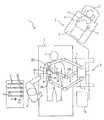
도 1a는 본 발명의 하나의 실시예에 따른 로봇 수술 시스템의 평면도이다.
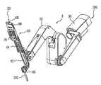
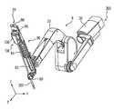
도 1b 및 1c는 각각, 머니퓰레이터 암의 베이스에서의 힘 센서를 포함하고,환자측의 로봇 머니퓰레이터 및/또는 내시경 또는 카메라 로봇 머니퓰레이터가 수술을 위해 미리구성되도록 하는 연동장치 또는 셋업 조인트를 배치하는, 머니퓰레이터 시스템의 실시예의 사시도 및 정면도이다.
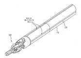
도 2는 본 발명의 하나의 실시예에 따라 텔레로보틱 수술 시스템으로 사용하는 손목, 그립 조, 및 힘 센서를 나타내는 수술 기기의 말단의 사시도이다.
도 3은 인가된 힘을 도시하는 도 2의 수술 기기의 제 1 탑뷰이다.
도 4는 인가된 힘을 도시하는 도 2의 수술 기기의 제 1 측면도이다.
도 5는 인가된 토크를 도시하는 도 2의 수술 기기의 제 2 탑뷰이다.
도 6은 인가된 토크를 도시하는 도 2의 수술 기기의 제 2 측면도이다.
도 7은 손목 메커니즘에 의해 인가된 로드와 모멘트에 대한 기기 샤프트와 인접한 손목 클레비스의 자유물체도를 도시한다.
도 8은 내장된 스트레인 게이지에 대한 홈이 있는 기기 샤프트를 도시한다.
도 9는 스트레인 게이지를 포함하는 기기를 도시한다.
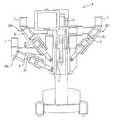
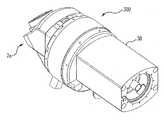
도 10은 본 발명의 하나의 실시예에 따라 머니퓰레이터의 베이스에서 힘 센서를 포함하는, 머니퓰레이터의 사시도이다.
도 11a 및 11b는 본 발명의 하나의 실시예에 따라 액세서리 클램프의 결합을 포함하는, 도 10의 머니퓰레이터의 사시도와 각각의 측면도이다.
도 12a 및 12b는 본 발명의 하나의 실시예에 따른 캐뉼러의 결합을 포함하는, 도 10의 머니퓰레이터의 사시도와 각각의 측면도이다.
도 13a 및 13b는 본 발명의 하나의 실시예에 따른 멸균 어댑터(sterile adapptor)의 결합을 포함하는, 도 10의 머니퓰레이터의 사시도와 각각의 측면도이다.
도 14a 및 14b는 본 발명의 하나의 실시예에 따른 기기의 결합을 포함하는, 도 10의 머니퓰레이터의 사시도와 각각의 측면도이다.
도 15는 상기 머니퓰레이터의 베이스 영역에서의 힘 센서의 근접 사시도를 도시한다.
도 16은 본 발명의 하나의 실시예에 따른 힘 센서의 예를 도시한다.
도 17a-17f는 본 발명의 실시예에 따라 F/T 센서, 셋업 연동장치 암, 및 머니퓰레이터 암의 베이스 사이의 기계 및 전기 커넥터 인터페이스를 도시한다.
도 18은 본 발명의 하나의 실시예에 따라 F/T 센서, 셋업 연동장치 암, 및 머니퓰레이터 암 사이의 데이터 결합의 블록도를 도시한다.
도 19a 및 19b는 본 발명의 하나의 실시예에 따른 F/T 센서에서의 스프링 평형추(conterbalance)를 도시한다.
도 20은 특정한 테스트 동안 베이스 장착 힘 센서를 포함하는 본 발명의 머니퓰레이터로부터의 힘을 판독할 때의 최대 편차를 도시한다.
도 21은 또다른 머니퓰레이터가 환자 외부의 본 발명의 머니퓰레이터에 충돌할 때 베이스 장착 힘 센서를 포함하는 본 발명의 머니퓰레이터로부터 판독한 힘을 도시한다.
도 22는 본 발명의 머니퓰레이터가 환자 외부의 또다른 머니퓰레이터에 충돌할 때 베이스 장착 힘 센서를 포함하는 본 발명의 머니퓰레이터로부터 판독한 힘을 도시한다.
도 23은 본 발명의 머니퓰레이터가 점진적으로 힘을 증가시켜서 봉합선을 파열시킬 때 베이스 장착 힘 센서를 포함하는 본 발명의 머니퓰레이터로부터 판독한 힘을 도시한다.
도 24는 본 발명의 머니퓰레이터가 봉합선을 파열하기 전에 계속하여 변하는 힘을 제공할 때 베이스 장착 힘 센서를 포함하는 본 발명의 머니퓰레이터로부터 판독한 힘을 도시한다.
도 25는 본 발명의 머니퓰레이터 기기가 또다른 머니퓰레이터의 기기에 충돌할 때 베이스 장착 힘 센서를 포함하는 본 발명의 머니퓰레이터로부터 판독한 힘을 도시한다.
본 발명의 실시예와 그의 이점들은 하기의 상세한 설명을 참조하여 가장 잘 이해될 것이다. 유사한 번호는 하나 이상의 도면에서 도시된 유사한 엘리먼트를 식별하기 위해 사용된다는 것을 이해해야 한다. 도면이 필수적으로 크기를 나타내는 것은 아님을 이해해야한다.1A is a top view of a robot surgical system in accordance with one embodiment of the present invention.
Figures 1b and 1c each illustrate a manipulator system, including a force sensor at the base of the manipulator arm, for positioning an interlocking device or set-up joint that allows the patient's robot manipulator and / or endoscope or camera robotic manipulator to be pre- Fig. 3 is a perspective view and a front view of the embodiment of Fig.
Figure 2 is a perspective view of the distal end of a surgical instrument representing a wrist, gripping jaw, and force sensor for use in a telerobic surgical system in accordance with one embodiment of the present invention.
Figure 3 is a first top view of the surgical instrument of Figure 2 showing the applied force.
4 is a first side view of the surgical instrument of FIG. 2 showing an applied force.
Figure 5 is a second top view of the surgical instrument of Figure 2 showing the applied torque.
Figure 6 is a second side view of the surgical instrument of Figure 2 showing the applied torque.
Figure 7 shows a free object view of the wrist clevis adjacent to the device shaft for the load and moment applied by the wrist mechanism.
Figure 8 shows a slotted device shaft for an embedded strain gage.
Figure 9 shows a device including a strain gauge.
10 is a perspective view of a manipulator including a force sensor at the base of a manipulator in accordance with one embodiment of the present invention.
11A and 11B are a side view and a perspective view, respectively, of the manipulator of FIG. 10, including the coupling of an accessory clamp according to one embodiment of the present invention.
12A and 12B are a side view and a perspective view, respectively, of the manipulator of FIG. 10, including a coupling of a cannula according to one embodiment of the present invention.
Figures 13a and 13b are perspective and respective side views of the manipulator of Figure 10, including the coupling of sterile adapters according to one embodiment of the present invention.
14A and 14B are a side view and a perspective view, respectively, of the manipulator of FIG. 10, including the coupling of devices in accordance with one embodiment of the present invention.
Figure 15 shows a close-up perspective view of a force sensor in the base region of the manipulator.
16 shows an example of a force sensor according to one embodiment of the present invention.
17A-17F illustrate mechanical and electrical connector interfaces between the F / T sensor, the setup interlocking arm, and the base of the manipulator arm in accordance with an embodiment of the present invention.
18 shows a block diagram of data coupling between an F / T sensor, a setup interlock device arm, and a manipulator arm in accordance with one embodiment of the present invention.
Figures 19a and 19b illustrate the spring balance cone in the F / T sensor according to one embodiment of the present invention.
Figure 20 shows the maximum deviation in reading force from a manipulator of the present invention including a base mounted force sensor during a particular test.
Figure 21 shows the force read from the manipulator of the present invention including a base mounted force sensor when another manipulator collides with the manipulator of the present invention outside the patient.
Figure 22 illustrates the force read from the manipulator of the present invention including a base mounted force sensor when the manipulator of the present invention impacts another manipulator outside the patient.
23 illustrates the force read from the manipulator of the present invention including a base mounted force sensor when the manipulator of the present invention gradually increases the force to rupture the seam line.
Figure 24 illustrates the force read from the manipulator of the present invention including a base mounted force sensor when the manipulator of the present invention provides a continuously changing force before the seam line ruptures.
Figure 25 shows the force read from a manipulator of the present invention including a base mounted force sensor when the manipulator device of the present invention impacts another manipulator device.
Embodiments of the present invention and its advantages will be best understood by reference to the following detailed description. It should be understood that like numbers are used to identify like elements shown in one or more of the figures. It should be understood that the drawings are not necessarily to scale.
본 발명은, 특히 오픈 수술, 신경외과 수술, 및 관절경 검사, 흉강경 검사 등과 같은 내시경 수술을 포함하는 환자에 대한 로봇 보조 수술을 수행하는 동안 힘을 감지하는 멀티-컴포넌트 시스템, 장치 및 방법을 제공한다. 본 발명의 시스템 및 방법은 특히 외과의로 하여금 환자로부터 원격 위치에서 서보메커니즘을 통해 수술 기기를 조정하도록 하는 텔레로봇 수술 시스템의 일부로서 유용하다. 그를 위해, 본 발명의 머니퓰레이터 장치 또는 슬레이브가 대개 힘을 반영 또는 표시하는 텔레프레즌스 시스템을 형성하기 위해 적어도 6 이상의 자유도(예를 들면, 3의 자유도의 위치, 3의 자유도의 방향)를 가진 운동학적으로-등가인 마스터에 의해 구동된다. 적절한 슬레이브-마스터 시스템의 설명은 모든 목적에 대해 참조에 의해 본문에 그 전체가 통합된 미국 특허 제 6,574,355에서 찾아볼 수 있다.The present invention provides a multi-component system, device, and method for sensing force during a robot assisted surgery for a patient, particularly including open surgery, neurosurgical surgery, and endoscopic surgery such as arthroscopy, thoracoscopy, do. The system and method of the present invention are particularly useful as part of a telerobot surgical system that allows a surgeon to adjust a surgical instrument through a servo mechanism at a remote location from a patient. For that purpose, the manipulator apparatus or slave of the present invention may be used as a kinematic (for example, three degrees of freedom, three degrees of freedom direction) with at least six degrees of freedom to form a telepresence system, And is driven by a master that is equivalent to -. A description of a suitable slave-master system can be found in U.S. Patent No. 6,574,355, which is hereby incorporated by reference in its entirety for all purposes.
본 발명의 로봇 시스템은 일반적으로 수술대에 인접하거나 또는 그에 장착된 하나 이상의 수술 머니퓰레이터 어셈블리 및 외과의로 하여금 수술 부위를 보고 상기 머니퓰레이터 어셈블리를 제어하도록 하는 마스터 제어 어셈블리를 포함한다. 시스템은 또한 하나 이상의 뷰잉 스코프 어셈블리와 상기 머니퓰레이터 어셈블리에 착탈가능하게 결합되도록 조정된 복수의 수술 기기(하기에 보다 상세히 기술됨)를 포함한다. 로봇 시스템은 적어도 2개의 머니퓰레이터 어셈블리, 바람직하게는 적어도 3개의 머니퓰레이터 어셈블리를 포함한다. 머니퓰레이터 어셈블리의 정확한 수는 다른 요인들 중에서도 수술과 수술실 내의 공간적 제약에 따른다. 하기에 상세히 기술된 바와 같이, 어셈블리들 중 하나는 일반적으로 다른 머니퓰레이터 어셈블리가 환자에 대한 다양한 처치를 수행하는 수술 기기를 작동시키는 동안 수술 부위를 보여주는 뷰잉 스코프 어셈블리(예를 들면, 내시경 수술에서)를 작동시킨다.The robotic system of the present invention generally includes one or more surgical manipulator assemblies adjacent to or attached to the operating table and a master control assembly that allows the surgeon to control the manipulator assembly to see the surgical site. The system also includes one or more viewing scope assemblies and a plurality of surgical instruments (described in more detail below) adapted to be removably coupled to the manipulator assembly. The robotic system includes at least two manipulator assemblies, preferably at least three manipulator assemblies. The precise number of manipulator assemblies depends on the surgical and surgical space constraints among other factors. As described in detail below, one of the assemblies generally includes a viewing scope assembly (e.g., in endoscopic surgery) that shows the surgical site while another surgical manipulator operates the manipulator to perform various treatments for the patient .
제어 어셈블리는 대개 외과의가 자신의 보조자(들)에게 말하고 직접 수술 처치를 모니터링하기 위해 수술대와 동일한 방에 위치한 외과의의 콘솔에 배치된다. 그러나, 외과의가 상이한 방 또는 환자로부터 전혀 상이한 건물에 위치할 수 있다는 것이 이해되어야 한다. 마스터 제어 어셈블리는 일반적으로 지지대, 수술 부위의 이미지를 외과의에게 표시하는 모니터, 및 머니퓰레이터 어셈블리를 제어하기 위한 하나 이상의 마스터(들)을 포함한다. 마스터(들)는 핸드헬드 손목 짐벌, 조이스틱, 장갑, 트리거-건, 수동식 컨트롤러, 음성 인식 디바이스 등과 같은 다양한 입력 디바이스를 포함한다. 바람직하게는, 마스터(들)는, 외과의가 수술 부위에 바로 인접해서 몰두해 있다는 인식인 텔레프레즌스와, 상기 외과의가 기기들이 자신의 손의 일부인 것처럼 기기들을 직접 그리고 직관적으로 제어하는 강력한 감각을 가지도록 하기 위해, 마스터(들)가 상기 기기들과 통합해 있다는 인식인 직관을 외과의에게 제공하기 위해 연관된 수술 기기 어셈블리와 동일한 자유도가 주어진다. 위치, 힘, 및 촉각 피드백 센서가 또한 텔레로보틱 시스템을 외과의가 작동할 때 수술 기기로부터 외과의의 손으로 위치, 힘 및 촉각을 다시 나타내도록 사용되는 신호를 전송하기 위해 기기 어셈블리 상에 채용된다. 오퍼레이터에게 텔레프레즌스를 제공하는 하나의 적절한 시스템 및 방법이 참조에 의해 본문에 미리 통합된 미국 특허 제 6,574,355에 기술된다.The control assembly is usually placed in the surgeon's console, which is located in the same room as the operating table, so that the surgeon speaks to his assistant (s) and directly monitors the surgical procedure. However, it should be understood that the surgeon may be located in a completely different building from a different room or patient. The master control assembly generally includes a support, a monitor that displays an image of the surgical site to the surgeon, and one or more master (s) for controlling the manipulator assembly. The master (s) include various input devices such as hand held wrist gimbals, joysticks, gloves, trigger-guns, hand-held controllers, speech recognition devices, and the like. Preferably, the master (s) has a telepresence, which is a perception that the surgeon is immersed immediately adjacent to the surgical site, and that the surgeon has a strong sense of direct and intuitive control of the devices as if they were part of their hands , The same degree of freedom as that of the associated surgical instrument assembly is provided to provide the surgeon with an intuitive perception that the master (s) is integral with the devices. A position, force, and tactile feedback sensor is also employed on the instrument assembly to transmit signals used to re-represent the position, force, and tactile sense of the surgical hand from the surgical instrument when the surgeon is operating the telobrotic system. One suitable system and method for providing telepresence to an operator is described in U.S. Patent No. 6,574,355, which is incorporated herein by reference in its entirety.
모니터는 수술 부위의 이미지가 외과의의 콘솔 상에서 외과의의 손에 인접하여 제공되도록 뷰잉 스코프 어셈블리에 적절하게 결합된다. 바람직하게는, 모니터는 외과의가 자신이 실제 수술 부위를 직접 들여다보고 있다고 느끼도록 방향을 설정하는 디스플레이 상에 이미지를 나타낸다. 그를 위해, 수술 기기의 이미지는, 관찰 포인트(즉, 내시경 또는 뷰잉 카메라)가 이미지의 관찰 위치에 있지 않을지라도 오퍼레이터의 손이 배치된 것으로 실제 배치된 것으로 나타낸다. 추가로, 실시간 이미지는 바람직하게는 오퍼레이터가 실제 프레즌스(true presence)로 워크피스를 보는 것처럼 엔드 이펙터와 핸드 제어를 조정할 수 있도록 스테레오 이미지로 변환된다. 실제 프레즌스에 의해, 이미지의 제시는 물리적으로 수술 기기를 조정하는 오퍼레이터의 시점을 시뮬레이션하는 트루 스테레오 이미지가 되는 것을 의미한다. 따라서, 컨트롤러(도시되지 않음)는, 스테레오 이미지가 예를 들면 카메라 또는 내시경이 직접 수술 기기의 바로 뒤에 배치된 것처럼 보는 이미지가 되도록 지각되는 위치로 수술 기기의 좌표를 변환한다. 이러한 가상 이미지를 제공하기 위한 적절한 좌표 변환 시스템은 모든 목적을 위해 참조에 의해 본문에 그 전체가 통합된, 1994년 5월 5일 미국 특허 출원번호 제 08/239,086으로 출원된, 현재 미국 특허번호 제 5,631,973에 기술된다.The monitor is suitably coupled to the viewing scope assembly such that the image of the surgical site is provided adjacent to the surgeon's hands on the surgeon's console. Preferably, the monitor displays an image on a display that directs the surgeon to feel that he is looking directly at the actual surgical site. For this purpose, the image of the surgical instrument is shown as being actually placed with the operator's hand placed, even though the observation point (i.e., the endoscope or viewing camera) is not at the observation position of the image. In addition, the real-time image is preferably converted to a stereo image so that the operator can adjust the end effector and hand control as if the operator were viewing the workpiece in true presence. By actual presence, the presentation of the image means that it becomes a true stereo image that simulates the operator's point of view physically adjusting the surgical instrument. Thus, a controller (not shown) converts the coordinates of the surgical instrument to a position where the stereo image is perceived to be an image that, for example, the camera or endoscope is viewed directly after the surgical instrument. A suitable coordinate transformation system for providing such a virtual image is described in U. S. Patent Application Serial No. 08 / 239,086, filed May 5, 1994, which is incorporated herein by reference in its entirety for all purposes. 5,631,973.
마스터의 기계적 움직임을 머니퓰레이터 어셈블리로 변환하는 서보 제어가 제공된다. 서보 제어는 머니퓰레이터 어셈블리와 별개이거나 또는 그와 통합된다. 서보 제어는 수술 기기로부터 수동식 마스터로 힘과 토크의 피드백을 제공한다. 추가로, 서보 제어는, 인식된 바람직하지 않은 상황(예를 들면, 환자에 대한 과도한 힘의 수행, 미스매칭된 인코더 판독 등)에 반응하여, 시스템 동작을 안전하게 중지시키거나 또는 적어도 모든 로봇 움직임을 금지시키는 안전 모니터링 컨트롤러를 포함한다. 하나의 예에서, 서보 제어는 바람직하게는 시스템이 빠르고 정확하게 외과의에 의해 사용된 빠른 손동작에 반응하지만, 바람직하지 않은 외과의의 손 떨림을 필터링할 수 있도록 적어도 10Hz의 범위의 3dB의 서보 대역폭을 가진다. 이러한 시스템으로 효과적으로 작동시키기 위해, 머니퓰레이터 어셈블리는 상대적으로 낮은 관성력을 가지고, 드라이브 모터는 상대적으로 낮은 기어비(ratio gear) 또는 풀리 커플링(pulley coupling)을 가진다. 임의의 적절한 종래 또는 특화된 서보 제어가 본 발명의 실시에서 사용될 수 있다.Servo control is provided to convert the mechanical motion of the master into a manipulator assembly. The servo control is separate from or integrated with the manipulator assembly. Servo control provides force and torque feedback from surgical instruments to passive masters. Additionally, the servo control may be used to safely stop system operation, or at least to stop all robot motion (e.g., a motion of the robot), in response to a recognized undesirable situation (e.g., And a safety monitoring controller for inhibiting the operation of the system. In one example, the servo control preferably has a servo bandwidth of 3 dB in the range of at least 10 Hz, so that the system responds quickly and accurately to fast hand movements used by the surgeon, but to filter out unwanted surgical hand tremors. To operate effectively with such a system, the manipulator assembly has a relatively low inertia force and the drive motor has a relatively low ratio gear or pulley coupling. Any suitable conventional or specialized servo control may be used in the practice of the present invention.
도면을 상세히 참조하면, 유사한 번호는 유사한 엘리먼트를 지시하고, 도 1a-1c는 본 발명의 하나의 실시예에 따른 최소 침습 로봇 수술을 수행하는 로봇 수술 시스템(1)의 컴포넌트를 도시한다. 시스템(1)은 그 전체가 참조에 의해 본 문에 통합된 미국 특허 번호 제 6,246,200에 보다 상세히 기술된 것과 유사하다.DETAILED DESCRIPTION Referring now in detail to the drawings, wherein like numerals designate like elements, FIGS. 1A-1C illustrate components of a
시스템 오퍼레이터(O)(일반적으로 외과의)는 수술대(T)에 누운 환자(P)에 대한 최소 침습 수술을 수행한다. 시스템 오퍼레이터(O)는 디스플레이(12)에 의해 표시된 이미지를 보고 외과의의 콘솔(3)에서 하나 이상의 입력 디바이스 또는 마스터(2)를 조정한다. 외과의의 입력 명령에 응답하여, 콘솔(3)의 컴퓨터 프로세서(4)는 수술 기기 또는 도구(5)의 이동을 지시하여, 조인트, 연동장치, 및 각각 텔레스코픽 삽입축을 가지는 머니퓰레이터 암을 포함하는 로봇의 환작측 머니퓰레이터 시스템(6)(본 예시에서는 카트기반 시스템)을 통해 기기의 서보-기계적인 이동을 하게한다. 하나의 실시예에서, 프로세서(4)는 엔드 효과기의 움직임이 시스템 오퍼레이터(O)의 손에서의 입력 디바이스의 움직임을 따라가도록 도구(5)의 엔드 이펙터의 움직임을 연관시킨다.The system operator O (typically a surgeon) performs minimally invasive surgery on the patient P lying on the operating table T. The system operator O views the image displayed by the
프로세서(4)는 일반적으로 데이터 처리 하드웨어 및 소프트웨어를 포함하고, 소프트웨어는 일반적으로 기계판독 코드를 포함한다. 기계판독 코드는 본문에 기술된 방법의 일부 또는 모두를 실행하기 위한 소프트웨어 프로그래밍 명령어를 구현한다. 프로세서(4)가 도 1의 간략한 개략도에서 단일 블록으로 도시되었지만, 프로세서는 다수의 데이터 처리 회로를 포함하고, 상기 처리의 적어도 일부는 선택적으로 입력 디바이스에 인접하여 수행되고, 일부는 머니퓰레이터 등에 인접하여 수행된다. 임의의 다양한 폭넓은 중심화된 또는 분산된 데이터 처리 아키텍처가 채용될 수 있다. 유사하게, 프로그래밍 코드는 다수의 개별 프로그램 또는 서브루틴으로서 구현되거나, 또는 본문에 기술된 로봇 시스템의 다수의 다른 측면에 통합될 수 있다.The
하나의 예시에서, 머니퓰레이터 시스템(6)은 적어도 4개의 로봇 머니퓰레이터 어셈블리를 포함한다. 3개의 셋업 연동장치(7)(본 예시에서 카트의 측면에 장착된)는 전체적으로 수술의 적어도 일부 동안 고정된 위치에 머니퓰레이터(8)의 베이스를 지지하는 연동장치(7)로 머니퓰레이터(8)를 지지하고 배치한다. 머니퓰레이터(8)는 조직의 로봇 조정을 위해 수술 도구(5)를 이동시킨다. 하나의 추가적인 연동장치(9)(본 예시에서 커트의 중심에 장착된)가 내부 수술 부위의 이미지(바람직하게는 입체경의 이미지)를 캡처하기 위해 내시경/카메라 프로브(11)의 움직임을 제어하는 머니퓰레이터(10)를 지지 및 배치한다. 환자측 시스템의 포지셔닝 연동장치(7, 9)의 고정가능한 부분은 본문에서 대개 "셋업 암"이라고 한다.In one example, the
보조자(A)는 각각 셋업 연동장치 암(7, 9)을 이용하여 환자(P)에 대해 머니퓰레이터(8, 10)를 미리 배치하고; 대안의 수술 도구 또는 기기(5')로 하나 이상의 수술 머니퓰레이터로부터 도구(5)를 바꾸고; 연관된 비로봇 의학 기기 및 장비를 작동시키고; 상이한 어퍼처를 통해 연관된 도구가 내부 수술 부위로 액세스하도록 머니퓰레이터를 수동으로 움직이는 등의 것을 보조한다.The assistant A previously arranges the
일반적인 표현으로, 연동장치(7, 9)는 환자측 머니퓰레이터 시스템(6)의 셋업 동안 주로 사용되고, 일반적으로 수술 중 적어도 일부동안 고정된 구성으로 유지된다. 머니퓰레이터(8, 10)는 각각 외과의의 콘솔(3)의 지시에 따라 능동적으로 분절작동하는 구동 연동장치를 포함한다. 셋업 암의 하나 이상의 조인트가 선택적으로 구동되고 로봇 제어되지만, 셋업 암 조인트의 적어도 일부는 보조자(A)에 의해 수동 배치하도록 구성될 수 있다.In general terms, the
본 발명의 하나의 실시예에 따라, 힘/토크 (F/T) 센서(300)가 머니퓰레이터(예를 들면, 머니퓰레이터(8 또는 1O))의 베이스와 각각 결합된 셋업 연동장치(예를 들면, 연동장치(7 또는 9))의 바깥쪽 사이에 동작가능하게 결합된다. 하나의 예시에서, F/T 센서(300)의 하나의 측면은 패시브 셋업 암 연동장치의 단부에 동작가능하게 부착되고, F/T 센서(300)의 다른 측면은 서보작동 머니퓰레이터의 베이스에 동작가능하게 부착된다. 또다른 예시에서, 적어도 6의 자유도가 베이스로부터 기기에 대해 제공된다(기기의 손목으로부터의 방위에서 3의 자유도, 머니퓰레이터로부터의 위치에서 3의 자유도). 다소의 자유도는 또한 본 발명의 범위 내에 있다. F/T 센서(300)와 사용 방법의 상세한 기술은 하기에 보다 상세히 제공된다.According to one embodiment of the present invention, a force / torque (F / T)
하나의 예시에서, 내부 수술 부위의 이미지가 외과의의 콘솔(3)의 입체경 디스플레이(12)에 의해 오퍼레이터(O)에 도시된다. 내부 수술 부위는 보조 디스플레이(14)에 의해 보조자(A)에게 동시에 표시된다.In one example, an image of the internal surgical site is shown on the operator O by the
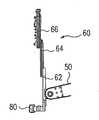
머니퓰레이터의 일부는, 다른 실시예에서, 머니퓰레이터의 모두가 텔레스코픽 삽입축을 포함할지라도, 텔레스코픽 삽입축(예를 들면, 도 10, 11a-14b의 텔레스코픽 삽입축(60))을 포함한다. 텔레스코픽 삽입축(60)은 하나의 예시에서, 하기에 보다 상세히 기술된 바와 같이 시스템 사용자에 대해(다른 이점에 추가하여) 이전의 설계에 비해 개선된 견고성 및 강도, 더 큰 이동 범위 및 개선된 동적 성능과 수술 필드에 근접한 가시성을 가진, 3개의 동작가능하게 결합된 링크를 통한 장착된 기기(예를 들면, 기기(5 또는 10))의 움직임을 허용한다.A portion of the manipulator includes, in other embodiments, a telescopic insertion axis (e.g.,
편의를 위해, 조직을 다루는 데에 사용되는 수술 도구를 지지하는 머니퓰레이터(8)와 같은 머니퓰레이터를 환자측 머니퓰레이터(PSM)라고 하는 반면, 내시경(11)과 같은 이미지 캡처 또는 데이터 획득 디바이스를 제어하는 머니퓰레이터(10)를 내시경 카메라 머니퓰레이터(ECM: endoscope-camera manipulator)라고 한다. 머니퓰레이터는 수술에 유용한 폭넓은 다양한 기기 또는 도구, 이미지 캡처 디바이스 등을 선택적으로 작동, 조종, 및 제어한다.For convenience, a manipulator, such as a
기기(5 또는 100) 및 내시경(11)은 수술을 위해 셋팅할 때, 상이한 페이지의 수술을 위해 머니퓰레이터 시스템(6)을 재설정할 때, 기기를 제거하거나 또는 대안의 기기(5')로 대체할 때 등에, 수동으로 배치된다. 이러한 보조자(A)에 의한 머니퓰레이터 어셈블리의 수동 재설정 동안, 머니퓰레이터 어셈블리는 마스터/슬레이브 원격 수술동안 사용되는 것과 상이한 모드인, 클러치 모드라고 하는 수동으로 재배치가능한 모드로 배치된다. 머니퓰레이터 어셈블리는 머니퓰레이터(8) 상의 버튼 또는 스위치(예를 들면, 도 11a-14b에서의 클러치 버튼/스위치(68)), 또는 머니퓰레이터 어셈블리에 대한 기타 컴포넌트를 누르는 것과 같은 입력에 반응하여 조직 조정 모드와 클러치 모드 사이에서 변경되어, 보조자(A)로 하여금 머니퓰레이터 모드를 변경시킬 수 있도록 한다.The
도 1a-1c에 도시된 바와 같이, 지시자(20)가 머니퓰레이터 어셈블리에 배치된다. 본 실시예에서, 지시자(20)는 머니퓰레이터와 그의 장착된 도구(5) 사이의 기기의 기계적 인터페이스에 인접하여 머니퓰레이터(8) 상에 배치된다. 대안의 실시예에서, 클러치 버튼/스위치(68)와 지시자(20)는 대신에 셋업 조인트(7, 9), 도구(5), 머니퓰레이터(8, 10) 등의 상의 임의의 위치에 배치될 수 있다. 지시자의 하나의 예는 모든 목적에 대해 참조에 의해 그 전체가 본문에 통합된(참조에 의해 그에 통합된 참조문헌을 포함하여) 2006년 11월 3일 출원된 미국 특허 출원 번호 제 11/556,484에 개시되어 있다.As shown in FIGS. 1A-1C, an
도 1a-1c와 함께 도 2-9를 참조하면, 외과의에 대한 힘 및/또는 토크의 감지 및 피드백을 위한 장치, 시스템 및 방법이 스트레인 게이지를 포함하는 수술 기기를 이용하는 것에 대해 기술된다. 하기에 기술된 기기는 본 발명의 머니퓰레이터와 함께 사용될 수 있는 힘 및/또는 토크 신호를 제공하는 예시적인 다양한 기기라는 것에 유의해야한다.Referring to Figures 2-9 in conjunction with Figures la-1c, an apparatus, system and method for sensing and feedback of force and / or torque on a surgeon is described using a surgical instrument comprising a strain gauge. It should be noted that the devices described below are various exemplary devices that provide force and / or torque signals that may be used with the manipulator of the present invention.
도 2는 수술 도구를 조정하고 및/또는 환자와 접촉하기 위해 사용되는 샤프트(110), 손목 조인트(112 및 114), 및 단부(120)를 포함하는 수술 기기(100)의 일부의 사시도를 도시한다. 수술 기기는 또한 멸균 어댑터 인터페이스를 통한 하나의 실시예에서, 로봇 머니퓰레이터 암과 동작가능하게 인터페이싱하는 하우징(150)(도 9)을 포함한다. 적용가능한 하우징, 멸균 어댑터 인터페이스, 및 머니퓰레이터 암은 모든 목적에 대해 그 전체가 참조에 의해 본문에 통합된 2005년 12월 20일 출원된 미국 특허출원 번호 제 11/314,040 및 2006년 12월 20일 출원된 미국 특허 출원 번호 제 11/613,800에 개시된다. 적용가능한 샤프트, 단부, 하우징, 멸균 어댑터, 및 머니퓰레이터 암의 예시는 캘리포니아 서니베일의 Intuitive Surgical Inc.에 의해 제조된다.2 illustrates a perspective view of a portion of a
바람직한 구성에서, 단부(120)는 x 및 y 축에 관한 피치 및 요 움직임, 및 z축에 관한 회전을 포함하는 이동 범위를 가진다(도 2에 도시된 바와 같은). 엔드 이펙터의 작동과 함께 머니퓰레이터(8)로부터의 움직임을 변환하는 이러한 움직임은 샤프트(110)와 하우징(150)을 통과하는 케이블을 통해 이루어진다. 드라이브 어셈블리, 암, 팔뚝 어셈블리, 어댑터, 및 기타 적용가능한 부분의 실시예는 모든 목적에 대해 참조에 의해 본문에 그 전체가 통합되는 미국 특허 번호 제 6,331,181, 6,491,701 및 6,770,081에 기술된다.In a preferred configuration, end 120 has a range of motion that includes pitch and yaw motion about the x and y axes, and rotation about the z axis (as shown in FIG. 2). This movement of converting the motion from the
조, 가위, 그래스퍼, 바늘 홀더, 마이크로-해부기구, 스테이플 어플라이어(staple applier), 트랙커, 흡입 관장 도구(sucktion irrigation tool), 클립 어플라이어, 절단 블레이드, 관주기(irrigator), 도뇨관, 및 흡입 오리피스와 같은, 엔드 이펙터를 구비하거나 구비하지 않은 도구를 포함하는 다양한 수술 기기가 사용되지만, 그에 한정되는 것은 아니다. 대안으로, 수술 기기는 조직을 제거, 절제, 절단, 또는 응고시키는 전자수술 프로브를 포함한다. 이러한 수술 기기는 캘리포니아 서니베일의 Intuitive Surgical, Inc.에 의해 제조된다.A staple applier, a tractor, a sucktion irrigation tool, a clip applier, a cutting blade, an irrigator, a catheter, and / or a catheter. Various surgical instruments are used, including, but not limited to, instruments with or without end effectors, such as suction orifices. Alternatively, the surgical instrument includes an electrosurgical probe for removing, ablating, cutting, or solidifying tissue. Such surgical instruments are manufactured by Intuitive Surgical, Inc. of Sunnyvale, CA.
하나의 예시에서, 기기부(100)는 z축이라고 하는, 샤프트의 장축(세로축)에 평행한 방향의, 샤프트(110)의 외부 표면에 장착된 센서(예를 들면, 스트레인 게이지)를 포함한다. 상기 샤프트에 수직인 2개의 축은 x축 및 y 축이라고 한다. 센서로부터의 신호는 기기의 팁 상에 가해진 3개의 직교하는 힘(예를 들면, Fx, Fy, 및 Fz)과 샤프트 축에 직교하는 2개의 축(즉, x축 및 y축)에 관한 토크(Tx, Ty)의 측정치를 얻기 위해 (하기에 보다 상세히 설명되는) 다양한 합과 차로 산술적으로 조합된다. 하나의 예시에서, 힘의 측정치는 기기의 말단에서의 손목 메커니즘의 방향과 유효한 레버의 암의 길이에 독립적으로 이루어진다. 단부(120)에 대해 가해진 힘은 힘 감지 엘리먼트에 의해 검출되며, 이는 이들 힘을 마스터(들)에게 전달하는 인터로게이터 또는 프로세서를 통해 서보 제어에 동작가능하게 결합될 수 있다. 스트레인 게이지를 포함하는 기기와 힘 감지의 방법의 예시가 모든 목적에 대해 그 전체가 참조에 의해 본문에 통합된 2006년 9월 29일 출원된 미국 특허 출원 번호 제 11/537,241 및 2006년 10월 26일 출원된 미국 특허 출원 번호 제 11/553,303에 개시된다.In one example, the
하나의 실시예에서, 8개의 스트레인 게이지(101, 102, 103, 104, 105, 106, 107, 및 108)가 샤프트(110)의 외부 표면 또는 외부 표면에 인접한 얕은 오목부에 장착되고, 스트레인 데이터(ε1, ε2, ε3, ε4, ε5, ε6, ε7, 및 ε8)를 각각 제공한다. 게이지의 주된 스트레인 감지 방향은 z축에 평행한 방향이다. 게이지들은 4개로 된 2개의 그룹으로 장착되며, 여기서 하나의 그룹의 4개의 게이지는 동일하게 공간을 두고 하나의 축 위치에서 샤프트의 주변으로 90°로 떨어져서 배치된다(즉, 4개의 스트레인 게이지 각각이 2개의 "링"을 형성한다). 4개(예를 들면, 게이지(101, 103, 105, 및 107))로 된 하나의 그룹은 샤프트(110)의 말단에 가능한 근접하게 손목 메커니즘에 인접하여 장착된다. 4개(예를 들면, 게이지(102, 104, 106, 및 108))로 된 제 2 그룹은 4개의 제 1 그룹(샤프트(110)의 인접 단부를 향해)으로부터 선택된 거리 "1"에 장착되고, 2개 그룹에서의 게이지 쌍이 서로 정렬되도록(즉, 게이지(101 및 102) 게이지(103 및 104), 게이지(105 및 106),및 게이지(107 및 108)) 제 1 그룹과 정렬된다.In one embodiment, eight
수술 기기의 힘과 손목 케이블의 힘 모두를 포함하는 z축 방향의 힘(Fz)은 팩터 EA/8이 곱해진 8개의 게이지 출력의 함으로부터 얻어질 수 있고, 여기서 E는 z축 방향의 샤프트 재료의 탄성계수이고, A는 샤프트의 단면적이다. 팁에 또는 그에 인접하여 x축 및 y축을 따라서 있는 측방향 힘(Fx 및 Fy)은 샤프트의 대향하는 측에서의 게이지 쌍의 게이지 출력의 차이와, 팩터 EI/2rl이 곱해진 샤프트를 따라서 있는 쌍의 차이로부터 얻어지고, 여기서 E는 z축 방향의 샤프트 재료의 탄성계수이고, r은 샤프트 축으로부터 게이지의 실행(acting) 평면까지의 반경이고, l은 4개 게이지의 2개의 그룹들 사이의 거리이다. 힘의 연산은 하기의 식으로부터 도출된다.The force in the z-axis direction (Fz ), including both the force of the surgical instrument and the force of the wrist cable, can be obtained from the box of eight gauge outputs multiplied by the factor EA / 8, A is the modulus of elasticity of the material, and A is the cross-sectional area of the shaft. The lateral forces Fx and Fy along the x and y axes at or near the tip are the difference between the gauge output of the gauge pair on the opposite side of the shaft and the pair along the shaft multiplied by the factor EI / Where E is the modulus of elasticity of the shaft material in the z-axis direction, r is the radius from the shaft axis to the acting plane of the gauge, l is the distance between the two groups of four gauges to be. The calculation of the force is derived from the following expression.
도 2에 대해,2,
E = σ/εE = σ / ε
A = π(ro2-ri2)A = π (ro2 -ri2 )
I = (π/4) (ro4-ri4)I = (? / 4) (ro4 -ri4 )
σ = (F/A) + (Mr/I)? = (F / A) + (Mr / I)
ε = [ε1 ε2 ε3 ε4 ε5 ε6 ε7 ε8]
ε = [ε1 ε2 ε3 ε4 ε5 ε6 ε7 ε8 ]

도 3 및 4에 대해,3 and 4,
A = π(ro2-ri2)A = π (ro2 -ri2 )
I = (π/4) (ro4-ri4)I = (? / 4) (ro4 -ri4 )
σ = Mr/Iσ = Mr / I
σ1 = FLr/Iσ1 = FLr / I
σ2 = F(L+l)r/I?2 = F (L + 1) r / I
E = σ/ε => ε = σ/EE = σ / ε => ε = σ / E
ε1 = -FxLr/EIε1 = -Fx Lr / EI
ε2 = -Fx(L+l)r/EI?2 = -Fx (L + l) r / EI
ε2 -ε1 = -Fxlr/EIε2 -ε1 = -Fx lr / EI
ε4-ε3= Fxlr /EI竜4 - 竜3 = Fx lr / EI
(ε4-ε3) - (ε2-ε1 ) = 2Fxlr/EI,(竜4 - 竜3 ) - (竜2 - 竜1 ) = 2Fx lr / EI,
따라서,therefore,
(ε1-ε2-ε3+ε4)EI/21r = Fx(?1 - ?2 - ?3 +?4 ) EI / 21r = Fx
(ε5-ε6-ε7+ε8 ) EI/21r = Fy(epsilon5- epsilon6- epsilon7 + epsilon8 ) EI / 21r =Fy
(ε1+ε2+ε3 +ε4 +ε5+ε6 +ε7+ε8)EA/8 = Fz(ε1 + ε2 + ε3 + ε4 + ε5 + ε6 + ε7 + ε8 ) EA / 8 = Fz
Fx 및 Fy는 따라서 L에 대해 불변이고, 정상 상태에서 온도에 대해 불변이다.Fx and Fy are It is therefore invariant to L and unstable to temperature in steady state.
이롭게도, 기기(100)는 손목 방위의 변화 또는 수술동안의 단부에서의 그립핑 위치 변화에 기인한 유효한 레버 암 길이에서의 변화에 대해 기기 팁에서의 측정된 횡방향 힘(Fx, Fy)이 독립적이 되도록 한다. 측정된 횡방향 힘은 또한 변화하는 손목 케이블 장력에 기인하여 특히 그에 대해 z축 방향 힘에서의 변화에 독립적이 되도록 한다. 추가로, 상기 측정된 횡방향 힘은 스트레인 게이지의 조합된 그룹에 말단에 인가된 수술 및 손목 마찰 유도 토크에 독립적이다. 마지막으로, x축 및 y축을 따라서 있는 측정된 힘은 모든 게이지에 대해 열평형시 온도 변화에 독립적이다. 이는 Fx 및 Fy에 대한 식에서 모든 4개의 게이지에 동일한 온도 변동 스트레인을 추가하고, 상기 요동이 상쇄되는 것을 봄으로써 알 수 있다. 게이지 온도가 동일하지 않은 동안의 열적 과도현상은 다른 측정치가 그를 위해 취해질 수 있다고 하더라도 본 설계에 의해 보상되지 못한다.Advantageously, the
기기 팁에서의 x축 및 y축에 관한 토크의 측정치(Tx, Ty)는 샤프트 직경을 가로지르는 쌍을 이루는 게이지의 차이와 팩터 EI/4r이 곱해진 샤프트 축을 따라서 있는 쌍의 차이의 합으로부터 도출되고, 여기서 다시 E는 축방향의 샤프트 재료의 탄성계수이고, I는 샤프트 부의 관성 모멘트이고, r은 샤프트 축으로부터 게이지의 실행 평면까지의 반경이다. 따라서, 기기의 팁에 가해진 힘(Fx, Fy, Fz)과 토크(Tx, Ty)는 예를 들면 그래스퍼에 유지된 조 또는 조직내에서의 봉합 바늘과 같은 그립핑된 도구의 위치 또는 손목의 방향에 기인하여 오차없이 측정된다. x축 및 y축에 관한 토크 측정치는 또한 정상 상태에서의 온도에 독립적이다. 토크의 연산은 하기의 식으로부터 도출된다.The measurements (Tx , Ty ) of the torques about the x and y axes at the tip of the instrument are the sum of the differences of the pairing along the shaft axis multiplied by the factor EI / 4r and the difference of the pairing gauge across the shaft diameter Where E is the modulus of elasticity of the shaft material in the axial direction, I is the moment of inertia of the shaft portion, and r is the radius from the shaft axis to the running plane of the gauge. Thus, the forces (Fx , Fy , Fz ) and torques (Tx , Ty ) applied to the tip of the instrument can be controlledby , for example, gripping tools The position of the wrist or the direction of the wrist. The torque measurements for the x and y axes are also independent of the temperature in the steady state. The calculation of the torque is derived from the following expression.
도 2와 함께, 도 5 및 6에 대해,
Referring to Figures 5 and 6, in conjunction with Figure 2,

σ = Mr/Iσ = Mr / I
σ1 = σ2 = Tr/Iσ1 = σ2 = Tr / I
E = σ/ε => ε = σ/EE = σ / ε => ε = σ / E
ε1 = ε2 = Tr/EI?1 =?2 = Tr / EI
따라서,therefore,
(ε1+ε2-ε3-ε4)EI/4r = Ty(竜1 + 竜2 - 竜3 - 竜4 ) EI / 4r = Ty
(-ε5-ε6+ε7+ε8)EI/4r = Tx(-ε5 -ε6 + ε7 + ε8 ) EI / 4r = Tx
다수의 구성이 가능하지만, 기기(100)는 바람직하게는, 하나의 예에서, 모든 게이지가 일정한 z축에 평행한 방향이고 그리고 용이하게 특성화된 탄성 특성을 가지기 때문에, 이방성 선형 파이버 강화 폴리머 관으로 구성된다. 유사한 이점이 적절하게 특징을 가진 직조형(woven) 강화 관으로 얻어지고, 상기 방법은 또한 균일한 탄성 특성의 관에 적용가능하다.Although a number of configurations are possible, the
하나의 예시에서, 종래의 호일형 저항 게이지, 반도체 게이지, 브래그 격자 또는 패브리-페로 기술을 이용한 광 파이버형 게이지, 및 스트레인 감지 표면 음향파(SAW) 디바이스와 같은 기타의 것 등을 포함하는 다양한 스트레인 게이지가 사용될 수 있지만, 그에 한정되는 것은 아니다. 광 파이버 브래그 격자(FBG) 게이지는 2개의 감지 엘리먼트가 공지된 거리에서 하나의 파이버를 따라 배치되어, 기기의 샤프트를 따라서 4개의 파이버만을 필요로한다는 점에서 이점을 가진다.In one example, a variety of strains, including conventional foil type resistance gauges, semiconductor gauges, Bragg gratings, fiber optic gauges using Fabry-Perot technology, and others such as strain sensing surface acoustic wave (SAW) Gages may be used, but are not limited thereto. An optical fiber Bragg Grating (FBG) gauge has the advantage that two sensing elements are disposed along one fiber at known distances, requiring only four fibers along the device's shaft.
본 발명을 한정할 의도를 가지지 않고, 예시로서, 2개의 상용 파이버 스트레인 게이지 기술이 사용될 수 있다. 패브리-페로 기술은 캐나다 쿼벡의 FISO Technologies, Inc.로부터 구입가능하며, 보다 상세한 정보는http://www.fiso.com에서 볼 수 있다. 파이버 브래그 격자(FBG) 게이지 기술은 영국 브랙널의 Smart Fibres Ltd.에서 구입가능하며, 보다 상세한 정보는http://www.smartfibres.com에서 볼 수 있다.Without intending to limit the invention, for example, two commercially available fiber strain gauge techniques may be used. Fabry-Perot technology is available from FISO Technologies, Inc. of Québec, Canada, and more information isavailable athttp://www.fiso.com . Fiber Bragg Grating (FBG) gauge technology is available from Smart Fibers Ltd., Bracknell, UK, and more information isavailable athttp://www.smartfibres.com .
다수의 FBG는 그것들이 상이한 범위의 파장을 이용하여 상술한 바와 같은 방식으로 형성된다면 파이버로 기록될 수 있고, 이는 특히, 각각이 공지된 거리 만큼 이격되어 있는 2개의 FBG를 가지는 4개의 파이버만 상기 기기 샤프트로 내장될 필요가 있기 때문에 이중 링의 스트레인 게이지 실시예에 대해 특히 유용한 특성이 있다. 패리-페로 기술로 이중 링 배치의 스트레인 게이지를 구현하기 위해, 8개의 파이버가 요구된다.A plurality of FBGs can be recorded as fibers if they are formed in the manner described above using different ranges of wavelengths, especially if only four fibers having two FBGs, each separated by a known distance, There is a particularly useful property for a strain gage embodiment of a dual ring because it needs to be built into the device shaft. To implement the strain gage of dual ring arrangement with the Parry-Perot technology, eight fibers are required.
파이버 기술 모두는 광학적으로 인코딩된 스트레인 정보를 로봇 수술 시스템의 컴퓨터 제어 하드웨어와 호환되는 전기 신호로 디코딩하는 인터로게이터 유닛을 필요로한다. 프로세서는 그런다음 스트레인 게이지/센서로부터의 신호와 함께 상술한 식들에 따라 힘들을 연산하기 위해 사용된다. 하나의 실시예에서, 인터로게이터 유닛(170)(도 9)이 머니퓰레이터 또는 수술 시스템의 임의의 위치에 장착되며, 이는 멸균 경계 전체에서 광 파이버의 라우팅을 필요로 한다. 하나의 경우에, 머니퓰레이터로의 기기의 설치가 자동으로 상기 기기와의 광학 링크를 형성하도록 하기 위해, 광학 커플링이 상기 머니퓰레이터와의 표준 기기의 기계적 인터페이스로 통합된다. 이롭게도, 이는 기기로 외부 케이블을 운반할 필요성을 방지한다. 제 2 경우에, 파이버 접속용 전선이, 상기 기기의 기계적 인터페이스의 일부가 아닌 머니퓰레이터 상에 놓인 커넥터와 짝을 이루기 위해 기기의 탑을 빠져나온다. 이러한 2가지 경우에, 인터로게이터가 머니퓰레이터로 장치되거나 또는 파이버 케이블이 머니퓰레이터를 통과하여 수술 시스템 또는 머니퓰레이터와 이격되어 있는 수술실에 장착된 인터로게이터로 관류한다. 제 3의 경우에, 파이버 접속용 전선은 머니퓰레이터와 이격된 수술실에 장착된 인터로게이터 유닛과 짝을 이루기 위해 머니퓰레이터를 통과하여 지나지 않으면서 기기의 탑을 빠져나오고, 이는 상기 기기가 머니퓰레이터로 부착될 때 또는 그로부터 제거될 때 파이버 케이블의 연결을 필요로하지 않는 효익을 가진다.Fiber technology requires an interrogator unit that decodes the optically encoded strain information into electrical signals that are compatible with the computer control hardware of the robotic surgery system. The processor is then used to calculate forces in accordance with the above-described equations with signals from the strain gage / sensor. In one embodiment, an interrogator unit 170 (Fig. 9) is mounted at any position of the manipulator or surgical system, which requires the routing of the optical fiber throughout the sterilization boundary. In one case, the optical coupling is integrated into the mechanical interface of the standard instrument with the manipulator, so that the installation of the instrument to the manipulator automatically forms the optical link with the instrument. Advantageously, this avoids the need to carry external cables with the device. In the second case, the wire for fiber connection exits the top of the device to mate with a connector placed on a manipulator that is not part of the mechanical interface of the device. In these two cases, the interrogator is equipped with a manipulator, or a fiber cable is passed through the manipulator and into the surgical system or an interrogator mounted in an operating room spaced apart from the manipulator. In the third case, the wire for fiber connection exits the top of the device without passing through the manipulator to mate with the interrogator unit mounted in the operating room away from the manipulator, which causes the device to be attached to the manipulator And there is no need to connect a fiber cable when removed.
게이지 방향, 다수의 게이지, 및 출력의 기타 조합이 또한 가능하다. 2개의 링의 8개의 게이지 배치에 대한 유용한 간략화는 게이지 링 중 하나를 제거할 수 있다. 이러한 간략화는 주어진 축(예를 들면, x 또는 y)에 대한 힘과 모멘트 사이를 구별할 기능을 제거하지만, 수술 환경에서의 다수의 아이템(예를 들면, 인체 조직, 봉합선)은 모멘트를 지원하지 않고, 따라서 모든 스트레인 정보는 x축 및 y축 힘으로부터 나온 것이라고 가정할 수 있다. 추가적인 실시예에서, 120°이격된 3개의 게이지가 90°이격된 4개의 게이지를 대신하는 세트를 형성하기 위해 사용될 수 있다. 따라서, 게이지의 조합은 120°이격된 3개의 게이지로 된 단일 링, 각각 120°이격된 3개의 게이지로 된 2개의 링(즉, 총 6개의 게이지), 90°이격된 4개 게이지로 된 단일 링 및, 각각 90°이격된 4개의 게이지로 된 2개의 링(즉, 총 8개의 게이지)을 포함할 수 있다. 단일 링 게이지의 실시예가 프로브와 같은 비손목(non-wristed) 도구에 유용하다. 게이지는 또한 샤프트 축에 대한 추가적인 토크 신호(Tx)의 복구를 허용하는 각도로 샤프트(110)의 표면 상에서 방향을 가질 수 있다. 그러나, 축에서 벗어난 샤프트의 탄성 특성이 고려되어야 한다.Other combinations of gauge directions, multiple gauges, and outputs are also possible. A useful simplification of the eight gauge arrangement of the two rings can eliminate one of the gauge rings. This simplification removes the ability to distinguish between forces and moments for a given axis (e.g., x or y), but many items in the surgical environment (e.g., human tissue, seams) , So all strain information can be assumed to be from the x- and y-axis forces. In a further embodiment, three gauges spaced 120 [deg.] Apart can be used to form a set instead of four gauges spaced 90 [deg.] Apart. Thus, the combination of gauges consists of a single ring of three gauges spaced 120 ° apart, two rings of three gauges spaced 120 ° apart (ie a total of six gauges), a single gauge of four gauges spaced 90 ° apart Ring and two rings of four gauges spaced 90 [deg.] Apart (i.e., a total of eight gauges). Embodiments of a single ring gauge are useful for non-wristed tools such as probes. The gauge may also be oriented on the surface of the
x 및 y 축의 힘이 상술한 바와 같은 기기의 샤프트 축의 말단의 센서(들)로 검출되고, z축 힘은 기기의 인접한 단부 근처의 신체 외부에 배치된 센서(들)로 검출될 수 있다. 스트레인 게이지 및/또는 파이버 기술을 포함하는 다양한 센서들이 z축 힘을 검출하기 위해 신체의 외부에서 사용될 수 있지만, 그에 한정되는 것은 아니다.The forces in the x and y axes are detected with the sensor (s) at the end of the shaft axis of the instrument as described above, and the z axis forces can be detected with the sensor (s) located outside the body near the proximate end of the instrument. Various sensors, including strain gage and / or fiber technology, may be used outside the body to detect the z-axis force, but are not limited thereto.
일반적으로, z축 힘은, 기기의 샤프트가 토크를 기기의 피치와 요 축에 전달하기 위해 필요한 내부 케이블로부터 z축 방향으로 현저한 내부 힘에 노출되기 때문에, 기기 팁에서 용이하게 감지될 수 없다. 이러한 케이블은 기기 샤프트의 내부를 관류하고, 실험은 샤프트에 대한 가압 로드는 상기 기기가 작동될 때 현저하게 변한다는 것을 나타낸다. 기기 샤프트에 대해 게이지로 z축 스트레인을 감지하고자 하는 시도는 관심 대상인 인가된 z축 힘에 추가하여 현저한 케이블 작동 "노이즈"를 포함한다. 따라서, 내부 케이블 힘을 거의 받지 않는 위치에서 z축 힘이 감지되는 것이 바람직하다. 케이블이 완전히 중심에 있는 것이 아니고 손목 풀리의 어느 한 측에 대한 케이블 텐션은 상기 손목이 작동될 때 변하기 때문에, 이러한 케이블은 또한 샤프트의 베이스에서의 일부 x 및 y 모멘트를 전달한다는 것에 유의해야한다. 그러나, 실험은, z축 방향의 케이블 힘과는 달리, 이들 편차는 예측된 외부 인가된 힘에 비해 상대적으로 작다는 것을 나타낸다.Generally, the z-axis force can not be easily detected at the instrument tip because the shaft of the instrument is exposed to significant internal forces in the z-axis direction from the internal cable required to transmit the torque to the instrument's pitch and yaw axis. This cable runs through the interior of the machine shaft and the experiment shows that the pressurized load to the shaft changes significantly when the machine is actuated. Attempts to detect z-axis strain on the gauge with respect to the machine shaft include significant cable operating "noise " in addition to the applied z-axis force of interest. Therefore, it is desirable that the z-axis force be sensed at a position that receives little internal cable force. It should be noted that the cable is not completely in the center and that the cable tension on either side of the wrist pulley changes when the wrist is actuated, so that this cable also transmits some x and y moments at the base of the shaft. However, the experiment shows that, unlike the cable forces in the z-axis direction, these deviations are relatively small compared to the predicted external applied forces.
z축 힘은 상대적으로 정확하게 신체 외부에서 검출되며, 주로 관심 신호에 "노이즈"를 추가하는 캐뉼러에서의 캐뉼러 실 마찰과 샤프트의 미끄럼 마찰을 가진다. 하나의 실시예에서, 캐뉼러 실은 1회용(disposable)이며 캐뉼러 실 표면에 결합되는 마찰 감소 윤활유 또는 마찰 감소 코팅(파릴렌과 같은)으로 패키징될 수 있다. 다른 실시예에서, 기기 샤프트 표면은 원하지 않는 마찰 노이즈를 감소시키기 위해 마찰 감소 코팅(예를 들면, PTFE)으로 처리될 수 있다. 마찰 감소 방법 모두는 또한 동시에 사용될 수 있다.The z-axis force is detected relatively accurately outside the body, and has primarily the cannula seal friction in the cannula and the sliding friction of the shaft, adding "noise" to the signal of interest. In one embodiment, the cannula seal is disposable and can be packaged with a friction reducing lubricant or friction reducing coating (such as parylene) that is bonded to the cannula seal surface. In another embodiment, the machine shaft surface may be treated with a friction reducing coating (e. G., PTFE) to reduce undesired friction noise. All of the friction reduction methods can also be used simultaneously.
하나의 예에서, 수술 기기의 인접한 단부에 인접하여 신체 외부의 다양한 위치에 센서가 배치될 수 있다. 1회용 기기 보다는 센서는 머니퓰레이터로 내장되는 것이 바람직하지만, 필수적인 것은 아니다. 하나의 실시예에서, 센서(들)(160)(도 9)가 머니퓰레이터 암 삽입 (z축) 캐리지 상에(예를 들면, 하기에 상술한 캐리지 링크상에) 기기의 멸균 어댑터를 위한 장착 포인트에 배치된다. 또다른 실시예에서, 센서(들)는 기기의 뒷판에 배치될 수 있다. 이는 센서를 멸균 어댑터 장착 포인트에 배치시키는 것과 실질적으로 등가이지만, 추가적인 센서를 모든 기기에 내장시키는 것을 필요로하는 것은 아니다.In one example, the sensors can be positioned at various locations outside the body adjacent to the proximal end of the surgical instrument. Though it is preferred that the sensor be embedded as a manipulator rather than a disposable device, it is not necessary. In one embodiment, sensor (s) 160 (Fig. 9) are mounted on a manipulator arm insertion (z axis) carriage (e.g., on a carriage link as described below) . In another embodiment, the sensor (s) may be located on the back plate of the device. This is substantially equivalent to placing the sensor at the sterile adapter mount point, but does not require the incorporation of additional sensors in all devices.
z축 힘과는 반대로, x축 및 y축 힘은, 비교적 작은 x 및 y축 조직 접촉력을 마스킹하는 원격 센터에서 전달된 큰 환자의 신체 벽의 힘과 토크에 노출된 캐뉼러와 접촉하기 때문에, 신체 외부에서 용이하게 감지될 수 없다. 따라서, x축과 y축 힘은 상술한 바와 같이 기기 손목 조인트에 인접한 기기 샤프트의 말단과 같은 신체 벽의 힘 또는 토크에 거의 노출되지 않는 위치에서 감지되는 것이 바람직하다. 상술한 내용에서, 내시경 수술 기기 샤프트의 튜브의 말단과 통합된 힘-토크 센서가 기술된다. 하나의 실시예에서, 센서는, 4개로 된 일 그룹의 멤버들이 샤프트의 주위로 90°로 이격되고 4개로 된 2개 그룹이 샤프트를 따라서 거리 1만큼 이격되도록, 샤프트의 주변에 관해 배치된 4개의 스트레인 게이지로 된 2개의 세트를 포함한다. 하나의 측면에서, 기기 팁 또는 조 상의 측면 로드(예를 들면, Fy)를 판정하는 것이 바람직하다. 개시된 내용은, 측 로드에 따른 각각의 그룹의 센서에서의 휨 모멘트(bending moment)를 연산하고 2개의 값을 나눔으로써, 손목 방향과 그의 결과인 효과적인 레버 암 길이에 독립적인 측 로드의 측정이 도출될 수 있다는 것을 설명한다. 중요한 것은, 기기 손목 축의 작동에 의해 샤프트의 최 끝단에 인가되고 손목 피봇에서의 마찰에 의해 샤프트에 전달되는 모멘트가 측면 로드의 의도한 측정치와 간섭된다는 것이다. 그러나, 측정된 스트레인을 수치적으로 제어하는 것을 통해 이러한 모멘트에 기인한 항(term)들을 자리올림(carry)함으로써, 이러한 모멘트에 기인한 항들은 측면 로드 힘이 연산될 때 드롭아웃(drop out)한다는 것을 알 수 있다. 유사하게, z축 힘들이 드롭아웃된다.As opposed to the z-axis force, the x-axis and y-axis forces are in contact with the cannula exposed to the force and torque of the large patient's body wall delivered in the remote center, masking the relatively small x and y-axis tissue contacting forces, It can not be easily detected from outside the body. Accordingly, it is desirable that the x-axis and y-axis forces are sensed at a position where they are hardly exposed to the force or torque of the body wall, such as the end of the device shaft adjacent to the device wrist joint, as described above. In the foregoing, a force-torque sensor integrated with the end of the tube of the endoscopic surgical instrument shaft is described. In one embodiment, the sensor is arranged in relation to the periphery of the shaft so that a group of four members is spaced 90 degrees around the shaft and the two groups of four are spaced apart by a
도 7과 하기의 식들을 참조하면, 8개의 스트레인 게이지에 의해 감지된 스트레인의 적절한 수치적 조합에 의해, 원하는 측면 로드힘을 보존하면서 원치않는 축방향 손목 케이블 힘과 속목 작동 토크를 제거하는 것이 가능하다. 도 7은 손목 메커니즘에 의해 인가된 로드와 모멘트를 받는 샤프트의 자유 물체도를 도시한다. 다양한 힘과 모멘트가 외부의 손목(120)의 자유 물체에 인가된다(도 6). 팁 로드, 케이블 로드, 및 손목의 움직임과 가속도에 따라, 샤프트의 y-z 평면에 표시된 샤프트(110)의 단부에 인가된 힘과 모멘트가 Fy(측면 로드), Fz(축방향 로드), 및 Mx(손목 피봇 마찰 모멘트 로드)로 감소한다.Referring to Figure 7 and the equations below, it is possible to eliminate undesired axial wrist cable forces and deaf-mideing working torques while preserving the desired side loading forces by appropriate numerical combination of strain sensed by the eight strain gauges Do. Figure 7 shows the free object of the shaft subjected to the load and moment applied by the wrist mechanism. Various forces and moments are applied to the free object of the outer wrist 120 (Fig. 6). Depending on the tip rod, cable rod, and wrist movement and acceleration, the forces and moments applied to the end of the
따라서, 상기 3개의 로드의 항에서 상기 평면의 4개의 게이지에 대한 스트레인 ε5 , ε6, ε7, 및 ε8을 표현하고, 하기와 같이 원하는 측면 힘 Fy에 대한 식을 도출할 수 있다.Therefore, in terms of the three rods, the strains?5 ,?6 ,?7 , and?8 for the four gauges of the plane can be expressed and an equation for the desired side force Fy can be derived as follows .
인장 변형률 > 0Tensile strain> 0
가압 스트레인 < 0Pressurized strain <0
ε7 = -FZ/EA + Mxr/EI + FyLr/EIε 7 = -F Z / EA + M x r / EI + F y Lr / EI
ε5 = -FZ/EA - Mxr/EI - FyLr/EIε5 = - FZ / EA - Mx r / EI - Fy Lr / EI
ε8 = -FZ/EA + Mxr/EI + Fy(l+L)r/EIε8 = -FZ / EA + Mx r / EI + Fy (1 + L) r / EI
ε6 = -FZ/EA - Mxr/EI - Fy(l+L)r/EIε 6 = -F Z / EA - M x r / EI - F y (l + L) r / EI
[(ε8-ε6)-(ε7-ε5)] = - FZ/EA [(1-l)-(1-l)][(竜8 - 竜6 ) - (竜7 - 竜5 )] = - FZ / EA [
+ Mxr/EI [(1-(-1)) -(1-(-1))]+ Mx r / EI [(1 - (- 1) - (1 - (- 1))]
+ Fyr/EI {[(l+L)-(-(l+L))]-[L-(-L)]}+Fy r / EI {[(l + L) - (- l + L)] - [L -
= 21Fyr/EI21Fy = r / EI
따라서,therefore,
Fy = [(ε8-ε6)-(ε7-ε5)]El/21rFy = [(竜8 - 竜6 ) - (竜7 - 竜5 )] El / 21r
Mx 및 Fx는 나타나지 않는다.Mx and Fx do not appear.
상술한 바와 같이, 게이지의 양 세트에 대해 동일하게 느껴지는 모멘트 로드 Mx에 의한 스트레인이 드롭아웃되고, 인가된 측면 힘 Fy에 의한 모멘트 로드를 남긴다. 게이지의 양 세트에 동일하게 느껴지는 축방향 힘 Fx에 의한 스트레인 컴포넌트 또한 드롭아웃된다. 따라서, 손목 작동 토크가 손목 조인트에서의 마찰에 의해 샤프트 전달 스트레인 센서로 전달되기 때문에, 이는 2개 세트의 센서로부터의 신호가 차감될 때 상쇄하는 모멘트 로드를 가져와, 원하는 대로 측면 로드 힘 만에 의한 상대적으로 깨끗한 신호를 남긴다. 상술한 기재내용은 x와 y가 교대로 발생하는 x-z평면에서의 ε1-4에 유사하게 적용한다.As described above, the strain due to the moment load Mx felt the same for both sets of gauges is dropped out, leaving a moment load due to the applied side force Fy . The strain component by the axial force Fx , which is felt equally in both sets of gauges, is also dropped out. Thus, since the wrist operating torque is transmitted to the shaft transfer strain sensor by friction at the wrist joint, this results in a moment load canceling when the signals from the two sets of sensors are subtracted, Leaving a relatively clean signal. The above description applies similarly to epsilon1-4 in the xz plane where x and y alternate.
이롭게도 실질적으로 측면 힘 로드 만에 의한 깨끗한 신호를 연산하는 것은 손목 마찰 모멘트를 제거하기 위해 미리 수행된 것과 같이 손목 조인트(최 끝단)의 외부에 센서를 배치할 필요성을 제거한다. 본 발명은 따라서 가요성 손목 조인트를 통해 스트레인 게이지에 연관된 와이어 또는 광 파이버를 라우팅할 필요성을 방지한다. 추가로, 요와 그립 축이 상술한 바와 같이 개별적으로 그것들을 구비하는 것이 아니라 동일한 피봇축 상에서 달성될 수 있다.Advantageously, computing a clean signal substantially only by the side force rods eliminates the need to place the sensor outside of the wrist joint (distal end) as previously performed to eliminate the wrist friction moment. The present invention thus avoids the need to route the wire or optical fiber associated with the strain gauge via the flexible wrist joint. In addition, the yaw and grip axes can be achieved on the same pivot axis rather than having them individually as described above.
상술한 모든 방법과 장치에 대해, 힘과 토크가, 기기 팁에 연속적으로, 동시에, 또는 보정 팩터와 오프셋이 Fx, Fy, Fz, Tx, 및 Ty를 얻기 위해 게이지 출력을 조합하기 위해 상술한 이론적인 식들에 적용하도록 판정되는 동안 조합하여 적용되는 교정 프로세스를 이용하는 것이 바람직하다. 교정은 보정 팩터 또는 오프셋을 직접 연산하거나 또는 교정 고정구 또는 기기 자체에 내장된 신경망과 같은 학습 시스템에 의해 달성될 수 있다 임의의 교정 방법에서, 교정 데이터는, 개별 기기를 이용하는 수술 시스템이 수술기기가 사용되는 동안 자신의 보정 팩터 및 오프셋을 정확하게 식별하고 그를 적용할 수 있도록 기기에 내장된 집적 회로로 프로그래밍될 수 있다.For all of the methods and apparatus described above, the force and torque may be combined with the gauge output to obtain Fx , Fy , Fz , Tx , and Ty continuously, simultaneously, It is desirable to use a calibration process that is applied in combination while being determined to apply to the theoretical formulas described above. Calibration may be accomplished by a learning system, such as a calibration factor or an offset directly, or by a learning system such as a calibration fixture or a neural network embedded in the instrument itself. In any calibration method, And can be programmed into the instrument's integrated circuit to accurately identify and apply its correction factor and offset during use.
기기 샤프트에 내장된 광 파이버는 바람직하게는 파이버의 물리적 무결성을 보존하면서 기기의 하우징/캐리지에 대한 샤프트의 회전을 방해하지 않는 방식으로 기기의 인접한 단부에 인접한 샤프트를 통해 벗어난다. 도 8 및 9를 참조하면, 패브리-페로 또는 FBG 감지 엘리먼트가 손목 클레비스 바로 뒤의 기기 샤프트의 최 끝단에 인접한 샤프트(110) 표면 바로 아래의 얕은 홈(130)에 내장되어, 에폭싱 되거나 또는 들어가 포팅된다. 홈(130)은 기기의 인접한 단부를 향해 나있으며, 이는 움직임 입력 및 손목 케이블 액추에이터 메커니즘("하우징")(150)을 포함한다. 홈(130)은 최초의 펄트루젼 프로세스(pultrusion process) 동안 샤프트에 형성되거나, 또는 홈은 샤프트 형성 후에 기계가공된다. 인접한 메커니즘 또는 하우징에 인접한 포인트에서, 파이버는 완만한 각도로 홈으로부터 라우팅되어 스트레인 릴리프(140)를 통과하여 광 파이버를 메커니즘 하우징(150)의 탑 커버 상의 스트레인이 해제된 앵커 포인트(142)로 이송하는 보호 가요성 외장으로 번들링된다. 가요성 외장(141), 스트레인 릴리프(140), 및 앵커 포인트(142)는 기기 샤프트(110)가 회전될 때 안전하고 반복된 수축과 토션을 허용하기 위해 충분한 길이와 가요성을 가져야 한다.The optical fiber embedded in the device shaft preferably escapes through the shaft adjacent the adjacent end of the device in a manner that does not interfere with the rotation of the shaft relative to the housing / carriage of the device while preserving the physical integrity of the fiber. 8 and 9, a Fabry-Perot or FBG sensing element may be embedded in a
또다른 실시예에서, 기기 샤프트가 수지와 파이버(예를 들면, 섬유유리 또는 탄소 섬유)로 만들어진다면, 광 파이버는 원하는 각도(90° 또는 120°)와 수지의 도포 이전에 기기 샤프트 파이버 매트릭스로의 방사형(표면에 인접한) 위치에서 선형 축방향 강화 파이버로 직조 또는 내장될 수 있다.In another embodiment, if the device shaft is made of resin and fiber (e.g., fiberglass or carbon fiber), then the optical fiber can have a desired angle (90 DEG or 120 DEG) and a device shaft fiber matrix (Adjacent to the surface) of the linear axial reinforcing fiber.
상술한 바와 같이, z축 힘은 상대적으로 정확하게, 주로 "노이즈"를 관심 신호에 추가하는 캐뉼러에서의 샤프트의 캐뉼러 실 마찰과 슬라이딩 마찰을 가지고, 신체의 외부에서 검출될 수 있다. 캐뉼러의 바람직한 실시예에서, z축 힘을 판정할 때 실질적으로 노이즈를 감소하기 위해 마찰을 감소시키는 캐뉼러 실, 기기, 및 사용 방법이, 참조에 의해 미리 본문에 통합된 미국 특허 출원 번호 제 11/864,974에 개시되어있다.As described above, the z-axis force can be detected from the outside of the body, with the cannula thread friction and sliding friction of the shaft in the cannula adding relatively "noise" In a preferred embodiment of the cannula, the cannula chamber, device, and method of use that reduce friction to substantially reduce noise when determining the z-axis force are disclosed in U. S. Patent Application No. < RTI ID = 0.0 > 11 / 864,974.
도 9를 참조하면, 기기(100)의 사시도가 도시된다. 하나의 실시예에서, 기기 샤프트(110)의 외부는 마찰 감소 코팅(예를 들면, 폴리테트라플루오로에틸렌(PTFE), 파릴렌, 또는 폴리아미드와 같은)으로 처리된 표면을 포함하고, 및/또는 바람직하지 못한 마찰 노이즈를 제거하는 마찰 감소 물질로 구성된다. 샤프트(110)는, 기기의 전체 샤프트가 최소 마찰 또는 방해로 캐뉼러 및/또는 캐뉼러 실을 통과하도록 상술한 바와 같은 기기 샤프트를 따라서 있는 홈에 배치된 스트레인 게이지를 덮는 균일한 직경을 가진다.Referring to Fig. 9, a perspective view of the
도 10-14b를 참조하면, 베이스에 장착된 F/T 센서(300), 머니퓰레이터 암 링크(50), 및 텔레스코픽 삽입 축(60)을 포함하는 머니퓰레이터(8)의 사시도 및 각각의 측면도가 본 발명의 하나의 실시예에 따라 도시된다. 도 10에서, F/T 센서 인터페이스(370)는 F/T 센서(300)에 동작가능하게 결합되고, 컴퓨터(380)는 선택적으로 F/T 센서 인터페이스(370)에 결합된다. 도 11a-11b는 액세서리 클램프(80)의 결합을 도시하고, 도 12a-12b는 캐뉼러(200)의 결합을 도시하고, 도 13a-13b는 기기의 멸균 어댑터(70)의 결합을 도시하고, 도 14a-14b는 기기(100)의 결합을 도시한다.10-14b, a perspective view and respective side views of the
하나의 실시예에서, 텔레스코픽 삽입 축(60)은 제 1 링크 또는 베이스 링크(62), 베이스 링크(62)에 동작가능하게 결합된 제 2 링크 또는 아이들러 링크(64), 및 아이들러 링크(64)에 동작가능하게 결합된 제 3 링크 또는 캐리지 링크(66)를 포함한다. 머니퓰레이터 중 일부는, 다른 실시예에서 머니퓰레이터들이 선형 슬라이딩 캐리지 또는 텔레스코픽 삽입축(60)을 포함할지라도, 텔레스코픽 삽입 축(60)을 포함한다. 그러나, 다른 실시예에서, 삽입 축(60)은 더 작은 또는 더 큰 수의 링크를 포함한다. 텔레스코픽 삽입 축(60)은 3개의 동작가능하게 결합된 링크를 통해, 이전의 설계에 비해 개선된 견고성 및 강도, 더 큰 이동 범위, 및 개선된 동적 성능과 시스템 사용자에 대한 수술 필드에 인접한 가시성을 가지고, 장착된 도구 또는 기기(100)를 이동시키는 것을 허용하고, 이는 모든 목적에 대해 본문에 참조에 의해 통합된 2006년 12월 20일 출원된 미국 특허 출원 번호 제11/613,800에 더 상세히 기술된다.In one embodiment, the
베이스 링크(62)는 머니퓰레이터 암 링크(50)의 말단에 동작가능하게 결합되고, 하나의 예시에서, 베이스 링크(62)의 말단에 부착된 액세서리 클램프(80)를 포함한다. 캐뉼러(200)는 액세서리 클램프(80)에 장착된다. 적용가능한 액세서리 클램프와 액세서리의 예로는 모든 목적에 대해 그 전체가 본문에 참조에 의해 통합된 2005년 9월 30일 출원된 미국 특허 출원 번호 제11/240,087에 개시된다. 적용가능한 멸균 어댑터와 기기 하우징의 예는 모든 목적에 대해 본문에 참조에 의해 통합된 2005년 12월 20일 출원된 미국 특허 출원 번호 제11/314,040, 2006년 3월 31일 출원된 미국 특허 출원 번호 제11/395,418에 개시된다.The
캐리지 링크(66)는, 기기의 하우징(예를 들면, 도 14a 및 14b의 하우징(150))에 동작가능하게(예를 들면, 전기적으로 및/또는 물리적으로) 결합할 수 있는, 기기 멸균 어댑터(ISA)(70)(도 13a-13b)에 동작 가능하게(예를 들면, 전기적으로 및/또는 물리적으로) 결합하기 위한 기기 인터페이스를 포함하고, 환자 내부의 기기의 깊이를 제어한다. 하나의 실시예에서, 멸균 어댑터는 로봇 수술 시스템을 멸균 포목으로 덮은 드레이프에 통합되고, 특히 비멸균 머니퓰레이터 암(예를 들면, 하기에 더 기술되는 환자측 머니퓰레이터)과 수술의 멸균 필드 사이에 멸균 장벽을 구축하기 위해 머니퓰레이터 시스템에 통합된다. 적용가능한 드레이프와 어댑터의 예는 모든 목적에 대해 본문에 참조에 의해 그 전체가 통합된 2005년 9월 30일 출원된 미국 특허 출원 번호 제 11/240,113에 개시된다. 기기 인터페이스의 예는 모든 목적에 대해 본문에 참조에 의해 그 전체가 통합된 2006년 12월 20일 출원된 미국 특허 출원 번호 제 11/613,695에 개시된다.The
아이들러 링크(64)는 링크(62, 64, 및 66)로 하여금 텔레스코핑 방식으로 세로축을 따라서 서로에 대해 이동할 수 있도록 베이스 링크(62)와 캐리지 링크(66) 사이에 이동가능하게 결합된다. 하나의 실시예에서, 베이스 링크(62)는 아이들러 링크(64) 보다 더 협소한 폼 팩터를 가지고, 아이들러 링크(64)는 캐리지 링크(66)보다 더 협소한 폼 팩터를 가져서, 수술 필드에 인접한 더 큰 가시성을 제공한다.The
편의를 위해, 조직을 다루는 데에 사용되는 수술 도구를 지지하는 머니퓰레이터(8)와 같은 머니퓰레이터를 환자측 머니퓰레이터(PSM)라고 하는 반면, 내시경과 같은 이미지 캡처 또는 데이터 획득 디바이스를 제어하는 또다른 머니퓰레이터를 내시경 카메라 머니퓰레이터(ECM)라고 한다. 머니퓰레이터는 수술에 유용한 폭넓은 다양한 기기 또는 도구, 이미지 캡처 디바이스 등을 선택적으로 작동, 조종, 및 제어한다.For convenience, a manipulator, such as
기기(100)는, 수술을 위해 셋팅할 때, 상이한 페이지의 수술을 위해 머니퓰레이터 시스템을 재설정할 때, 기기를 제거하거나 또는 대안의 기기로 대체할 때 등에, 수동으로 배치된다. 이러한 보조자에 의한 머니퓰레이터 어셈블리의 수동 재설정 동안, 머니퓰레이터 어셈블리는 마스터/슬레이브 원격 수술동안 사용되는 것과 상이한 모드로, 클러치 모드라고 하는 수동으로 재배치가능한 모드로 배치된다. 머니퓰레이터 어셈블리는 머니퓰레이터(8) 상의 버튼 또는 스위치(예를 들면, 도 11a-14b에서의 클러치 버튼/스위치(68)), 또는 머니퓰레이터 어셈블리에 대한 기타 컴포넌트를 누르는 것과 같은 입력에 반응하여 조직 조정 모드와 클러치 모드 사이에서 변경되어, 보조자로 하여금 머니퓰레이터 모드를 변경시킬 수 있도록 한다.The
도 15 및 16을 참조하면, 도 15는 셋업 연동장치 암(7)의 자유단(7a)과 머니퓰레이터(8)의 베이스(30) 사이의 F/T 센서(300)의 클로즈업한 사시도를 도시하고, 도 16은 기계적 또는 전기적 커넥터 인터페이스가 없는 F/T 센서(300)의 예를 도시한다.15 and 16 show a close-up perspective view of the F /
상술한 바와 같이, F/T센서(300)가 머니퓰레이터의 베이스(예를 들면, 도 1a-1c의 머니퓰레이터(8 또는 10)의 베이스(30))와 각각의 결합된 연동장치(예를 들면, 연동장치(7 또는 9)의 자유단(7a)에 있는) 외부 사이에 동작가능하게 결합된다. 하나의 실시예에서, 센서(300)는 베이스(30)와 연동장치의 자유단(7a) 사이에 동작가능하게 결합된다(도 1a-1c를 참조). 하나의 예시에서, F/T센서(300)의 하나의 측면은 패시브 셋업 암 연동장치의 단부에 동작가능하게 부착되고, F/T 센서(300)의 또다른 측면은 베이스(30)에서의 서보-작동 머니퓰레이터에 동작가능하게 부착된다. 또다른 예시에서, 적어도 6의 자유도가 베이스(30)에서 시작되는 머니퓰레이터(그리고 기기)에 제공된다. 특히, 환자 신체 외부의 요, 피치, 및 머니퓰레이터(8)의 삽입축 이동이 축(A, B, 및 C)을 따라서 제공된다(도 10). 기기 손목의 피치 및 요 이동, 기기의 회전 이동은 베이스(30)에서 시작하는(즉, 베이스에 말단인) 다른 3의 자유도를 제공한다. 다소의 자유도는 또한 본 발명의 범위 내에 있다. 예를 들면, 기기 엔드 이펙터의 시작과 끝에 또다른 자유도가 고려된다.As described above, the F /
하나의 예에서, F/T 센서(300)는 F/T 센서 인터페이스(370)(도 10)에 대해 힘과 토크를 아날로그 스트레인 게이지 신호로 변환하는 모놀리식 구조이다. 하나의 예시에서, 도 16에 도시된 바와 같이, 센서(300)는 센서로의 힘의 적용시 수축하는 3개의 대칭으로 배치된 빔을 포함한다. 빔은 하나의 예시에서 고체 금속으로부터 기계가공될 수 있다. 반도체 스트레인 게이지 또는 호일 저항 스트레인 게이지는 빔에 부착되어 x, y, z축에서의 힘과 토크의 컴포넌트(Fx, Tx, Fy, Ty, Fz, 및 Tz)에 연관된 스트레인 게이지 신호를 F/T 센서 인터페이스(370)로 제공하는 스트레인감지 레지스터로 고려된다.In one example, the F /
F/T 센서 인터페이스(370)와 센서(300) 사이의 통신은 센서 및 인터페이스로 연결하는 동작가능한 커넥터를 가진 전기 차폐된 케이블을 통해 달성된다. 유선 및 무선 통신 수단과 프로토콜을 포함하는, 센서(300)와 F/T 센서 인터페이스(370) 사이의 다양한 기타 통신 수단은 본 발명의 범위 내에 있다.The communication between the F /
F/T 센서 인터페이스(370)는 F/T 센서(300)로부터의 스트레인 게이지 데이터를 힘/토크 컴포넌트로 변환한다. 센서(300)에 대한 스트레인 게이지의 저항은 인가된 로드의 함수로서 변화한다. F/T 센서 인터페이스(370)는 저항의 변화를 측정하고 이러한 변화를 하드웨어와 소프트웨어 및 교정 데이터의 조합을 이용하여 힘과 토크 컴포넌트로 변환한다. F/T 센서 인터페이스(370)는 또한 센서 출력을 판독할 뿐만 아니라 센서(300)로 파워와 신호를 제공한다. 컴퓨터(380)(도 10)가 또한 스트레인 게이지 데이터를 더 처리하기 위해 F/T 센서 인터페이스(370)로 동작가능하게 결합될 수 있다. F/T 센서 인터페이스(370)는 직렬 입/출력 또는 아날로그 출력을 포함하는 다양한 수단(그러나 그에 한정되는 것은 아님)을 통해 컴퓨터(380)와 통신할 수 있다. 하나의 예시에서, F/T 센서 인터페이스(370)는 로(raw) 스트레인 게이지 데이터 및/또는 16진수 및 10진수 정수 포맷을 포함하는(그러나 그에 한정되는 것은 아님)다양한 포맷으로 분석된(resolved) 힘/토크 데이터를 출력한다.The F /
하나의 예시에서, F/T 센서(300)는 노스캐롤라이나 에이펙스의, ATI Industrial Automation에서 구입가능한, 모델 Theta라는, 힘/토크 변환기이고, F/T 센서 인터페이스(370)의 예로는 또한 노스캐롤라이나 에이펙스의, ATI Industrial Automation에서 구입가능한, 적용가능한 파워 서플라이 및 데이터 획득(DAQ) 카드 또는 컨트롤러 F/T 시스템이고, 이는 본 발명을 제한하는 것을 의도하지 않는다. 보다 상세한 정보는http://www.ati-ia.com에서 볼 수 있다.In one example, the F /
도 17a-17f를 참조하면, F/T 센서, 셋업 연동장치 암 및 머니퓰레이터 암의 베이스 사이의 기계 및 전기 커넥터 인터페이스가 본 발명의 하나의 실시예에 따라 도시된다.17A-17F, mechanical and electrical connector interfaces between the F / T sensor, the setup interlock arms and the bases of the manipulator arms are shown in accordance with one embodiment of the present invention.
정렬 슬롯 및 나사의 조합이 하나의 예시에서 셋업 연동장치와 머니퓰레이터 사이의 F/T 센서(300)의 기계적 결합을 위해 사용될 수 있다. 하나의 예시에서, 슬롯(302)이 셋업 연동 장치 자유단(7a)에 설치되고, 슬롯(328)은 베이스(30)에 설치되고, F/T 센서(300)는 자유단(7a)에 기계적으로 결합하는 기계적 및 전기적 커넥터 인터페이스(306)를 제 1 측면에 포함하고, 베이스(30)에 기계적으로 결합하는 기계적 및 전기적 커넥터 인터페이스(308)를 제 2 측면에서 포함한다. 인터페이스(306)는 슬라이딩 가능하게 슬롯(302)(도 17c 및 17d)에 결합하는 슬롯(316)과 슬라이딩 가능하게 슬롯(328)(도 17e 및 17f)에 결합하는 슬롯(310)을 포함한다. 하나의 예시에서, 슬롯과 나사는 센서에 맞물려서 센서를 셋업 연동장치와 머니퓰레이터의 베이스에 고정시킨다.The combination of alignment slots and screws can be used for mechanical coupling of the F /
또다른 예시에서, D-형 커넥터(플러그와 소켓)와 와이어의 조합이 파워와 데이터의 전달을 위해 셋업 연동장치와 머니퓰레이터 사이의 F/T 센서(300)의 전기 결합에 사용될 수 있다. 하나의 실시예에서, 셋업 연동장치 자유단(7a)은 개구(304a, 304b)에 들어맞는 소켓(314a, 314b)을 포함하고, F/T 센서(300)의 인터페이스(306)는 소켓(314a, 314b)(도 17c 및 17d)에 동작가능하게 결합하는 플러그(318a, 318b)를 포함한다. 또다른 실시예에서, 베이스(30)는 플러그(326a, 326b)를 포함하고, F/T 센서(300)의 인터페이스(308)는 플러그(326a, 326b)(도 17e, 17f)에 동작가능하게 결합하는 소켓(322a, 322b)을 포함한다. 하나의 실시예에서 F/T 센서(300)의 외부 표면 주위로 라우팅되는 차폐된 와이어(320)를 통해 플러그(318a, 318b)를 소켓(322a, 322b)으로 결합함으로써 파워와 데이터가 F/T 센서의 제 1 측면으로부터 제 2 측면으로 전달된다. 다른 실시예에서, 차폐된 와이어(320)는 F/T 센서(300)를 통해 라우팅될 수 있다.In another example, a combination of a D-type connector (plug and socket) and wire may be used for electrical coupling of the F /
도 18을 참조하면, F/T 센서(300), 셋업 연동장치 암(7), 및 머니퓰레이터 암(8) 사이의 데이터 신호 경로의 블록도가 본 발명의 하나의 실시예에 따라 도시된다. 하나의 실시예에서, F/T 센서 신호가, 머니퓰레이터 암(8)에서의 모터 센서(340)로부터 조인트 센서(346)를 포함하는 셋업 연동장치(7)를 통해 메인 컨트롤러로 전달하는 직렬 버스(342) 상의 추가 노드(예를 들면, 직렬 통신 보드(344)로 주입된다. 커넥터(330, 330', 332, 332')는 F/T 센서(300)와 머니퓰레이터(8) 및 셋업 연동장치(7) 사이의 전기 연결을 각각 허용한다. 하나의 예시에서, 커넥터(330, 330', 332, 332')는 도 17a-17f에 대해 상술한 D-형 커넥터와 유사하다. 이롭게도, 직렬 통신을 사용하면, 머니퓰레이터 모터 센서(340) 및 셋업 연동장치 조인트 센서(346)로부터의 센서 신호로 F/T 센서 신호의 시분할 멀티플렉싱이 가능하다.18, a block diagram of the data signal path between the F /
센서와 베이스 또는 연동장치 사이의 기타 기계적 전기적 맞물림 수단은 본 발명의 범위 내에 있다. 상술한 플러그와 소켓은 직렬 및/또는 병렬 커넥터이고, 암 커넥터 및 수 커넥터가 적절하게 스위칭될 수 있다. 이더넷, 범용 직렬 버스(USB), 및 파이어와이어와 같은 기타 유형의 전기 인터페이스가 또한 본 발명의 범위 내에 있다. 이롭게도, 상술한 기계적 전기적 맞물림 수단은 F/T 센서와 셋업 연동장치 또는 머니퓰레이터 베이스 사이의 효율적이고 단순한 기계적 및 전기적 메이팅을 허용한다.Other mechanical and electrical engagement means between the sensor and the base or interlock are within the scope of the invention. The above-described plug and socket are serial and / or parallel connectors, and the female connector and the male connector can be appropriately switched. Other types of electrical interfaces, such as Ethernet, Universal Serial Bus (USB), and FireWire, are also within the scope of the present invention. Advantageously, the mechanical and electrical engagement means described above allow efficient and simple mechanical and electrical mating between the F / T sensor and the setup interlock or manipulator base.
도 19a 및 19b를 참조하면, F/T 센서(400)를 위한 스프링 평형추가 본 발명의 하나의 실시예에 따라 도시된다. F/T 센서(400)는 하나의 예시에서 센서의 중심 허브(408)에 관한 4개의 스트럿(406)을 가진 하우징(404)을 포함한다. 본 실시예에서, 허브(408)는 머니퓰레이터에 동작가능하게 결합되고, 하우징(404)은 셋업 연동장치에 동작가능하게 결합된다. 스트레인 게이지가 상기 스트럿(406)에 장착된다. 스트링(402a, 402b)은 세로축 "z"를 따라서 있는 센서의 대향하는 단부에 그리고 수직축 "y"를 따라서 있는 중심 허브(408)의 위아래에 배치된다. 스프링(402b)의 힘은 중심 허브(408)에 장착된 머니퓰레이터의 무게와 같은 크기만큼 스프링(402a)의 힘보다 더 크다. 이롭게도, 스프링(402a, 402b)의 위치는 머니퓰레이터의 위에 걸린 로드 무게 및 모멘트를 상쇄한다. 만곡 빔 등과 같은 머니퓰레이터를 로드 보상 힘과 모멘트를 허브에 인가하는 다른 수단이 또한 가능하며 본 발명의 범위 내에 있다. 이러한 균형을 이루는 F/T 센서 설계는 안전한 스트레스 제한 내에서 작동하는 동안 머니퓰레이터를 지지하기위해 필요한 것보다 더 작은 스트럿을 가진 더 작고 가벼운 센서를 가능하게 한다. 게이지가 머니퓰레이터의 비보상의 정적인 과도한 로드에 대응하는 스트레인을 중심에 둔 것보다 더 많은 정도의 제로 스트레인 주위에 중심을 둔 게이지의 동적 범위에 대해 작용할 수 있기 때문에, 스트레인 게이지의 신호대 잡음비가 또한 개선된다. 어느 하나의 경우에, 게이지 또는 스트럿 스트레스에 의해 허용되는 최대 스트레인은 거의 동일하다. 마지막으로, 센서 허브와 외부 하우징의 기능은 스프링 위치가 결과적으로 변화된다면(예를 들면, 센서를 뒤집음으로써) 셋업 링크 및 머니퓰레이터에 대한 장착에 대해 역이 될 수 있다.Referring to Figs. 19A and 19B, a spring balance addition for the F /
동작시, 삽입축(60)은 캐뉼러(200)를 통해 절개하여 환자의 내부로 지나가는(도 14a-14b) 삽입축에 장착된 기기(100)를 포함한다. 머니퓰레이터(8)는 따라서 (1) 셋업 카트에 대해서는 F/T 센서(300)를 통해 패시브 셋업 연동장치(예를 들면 연동장치(7))로; 그리고 (2) 수술대에 대해서는 캐뉼러를 통해 환자 신체 벽에 대한 절개로 기계적 그라운드에 연결된다. 양 그라운드 경로 모두는 기계적 컴플라이언스를 가지며, 따라서 양 경로 모두는 기계적 그라운드에 대한 로봇 및 기기 로드를 공유한다. 따라서, 기기 팁에 대해 인가된 힘은 베이스에 장착된 F/T센서가 아니라 환자 신체 벽을 통해 부분적으로 기계적 그라운드로 지나간다.In operation, the
조합된 셋업 암 및 환자 신체벽의 컴플라이언스 때문에, 셋업 암의 단부에서의 조합된 베이스 장착 F/T 센서 및 로봇 매스의 진동 모드가 있다. 상이한 모드가 센서 신호에서 "노이즈"를 제거하기 위해 사용된다. 노치 필터가 힘 센서 및 로봇 매스의 진동에 의한 힘을 제거하기 위해 스트레인 게이지 데이터에 대해 사용된다. 저역 필터가 저주파 수술 힘만을 남기도록 스트레인 신호 상의 고주파 노이즈를 제거하기 위해 사용될 수 있다. 절개시 캐뉼러의 기울임에 의해 생성된 환자 신체 벽의 힘은 또한, 하나의 예에서 검색 테이블을 이용하여, 이러한 힘을 캐뉼러 기울임 각도의 함수로써 맵핑하고 총 감지된 힘으로부터 최종 추정 신체벽 힘을 차감함으로써 제거될 수 있다. 최소 감지 임계값이 또한 F/T 센서 노이즈 플로어 레벨 이하에서 힘을 제거하도록 사용될 수 있다. Due to the combined setup arm and patient body wall compliance, there is a combined base mounted F / T sensor at the end of the setup arm and a vibration mode of the robotic mass. Different modes are used to remove "noise" from the sensor signal. A notch filter is used for the strain gage data to remove the force due to the force sensor and the vibration of the robotic mass. Can be used to eliminate high frequency noise on the strain signal so that the low pass filter leaves only low frequency surgical force. The strength of the patient's body wall created by the tilting of the cannula at incision can also be determined by mapping this force as a function of the cannular tilt angle, using the look-up table in one example, and calculating the final estimated body wall force By subtracting < / RTI > The minimum sensing threshold can also be used to remove the force below the F / T sensor noise floor level.
베이스 장착 F/T 센서는 스트레인 게이지를 포함하거나 또는 포함하지 않는 기기와 함께 사용될 수 있다. 따라서, 다른 실시예에서는 베이스 장착 F/T 센서가 단독으로 사용되었지만, 베이스 장착 F/T 센서와 기기 스트레인 게이지가 x축, y축, 및 z축 힘 감지를 포함하는 로버스트 감지 시스템을 제공하기 위해 함께 사용될 수 있다. 하나의 실시예에서, 베이스 장착 F/T 센서는 서로간의 기기 샤프트의 충돌 및 신체 외부의 로봇 암의 충돌을 포함하는 기기 팁 센서에 대해 인접한 인가된 힘을 감지함으로써 상기 기기 팁 힘 센서를 증대시키는 데에 사용될 수 있다. 제 2 예시에서, 베이스 장착 F/T 센서가 상기 기기 팁 센서에 의해 측정된 기기의 x 및 y 축(횡단 축) 힘과 상기 베이스 장착 F/T 센서에 의해 측정된 분석된 기기의 z축(스템 튜브(stem tube) 축)의 힘을 조합함으로써 기기 팁 힘의 센서를 증대시키는 데에 사용될 수 있다.Base mounted F / T sensors can be used with instruments that include or do not include strain gages. Thus, while a base mounted F / T sensor and a device strain gage provide a robust sensing system that includes x-axis, y-axis, and z-axis force sensing, Can be used together. In one embodiment, the base mounted F / T sensor is configured to increase the instrument tip force sensor by sensing an adjacent applied force to an instrument tip sensor, including a crash of the instrument shaft between each other and a collision of the robot arm outside the body Can be used. In a second example, a base mounted F / T sensor measures the x and y axis (transverse axis) forces of the device measured by the device tip sensor and the z axis of the analyzed device measured by the base mounted F / T sensor Stem tube axis) to increase the sensor of the instrument tip force.
F/T 센서 인터페이스(370) 또는 컴퓨터(380)는 센서 노이즈를 감소시키기 위해 저역 필터(들), 노치 필터(들), 저신호 레벨 불감대, 및 그의 조합을 이용하여 베이스 장착 F/T 센서로부터의 스트레인 게이지 데이터를 필터링한다.The F /
하나의 예시에서, 저역 필터는 최초의 봉합선의 파열 및 파열을 일으키는 힘의 증가, 및 환자 신체 내부의 수술 기기 사이의 충돌을 검출하기 위한 힘/토크 데이터를 필터링하기 위해 사용될 수 있다.In one example, a low pass filter can be used to filter the force / torque data to detect an increase in force that causes rupture and rupture of the original suture line, and a collision between surgical instruments within the patient's body.
또다른 예시에서, 셋업 연동장치 암과 환자 신체 벽에 의해 순응적으로 한정된 머니퓰레이터 및 F/T센서의 매스의 공진에 대해 튜닝된 노치 필터가, 힘의 신호가 로봇 암의 이동에 의한 동적 힘에 의해 제어될 때 힘의 신호를 감쇠하기 위해 기기 팁 또는 로봇 암의 속도의 역수에 따라 센서 노이즈와 가변 이득 회로를 감소시키도록 저역 필터와 조합시 사용될 수 있다. 이러한 필터링 스킴은 예를 들면 최초의 봉합선 파열, 환자 신체 내부에서의 수술 기기 사이의 충돌, 조직 절개, 퇴축(retraction), 및 촉진(觸診)을 검출하기 위해 사용될 수 있다.In yet another example, a notch filter tuned for resonance of a mass of a manipulator and F / T sensor, which is confinedly defined by the setup interlocking arm and the patient body wall, Can be used in combination with a low pass filter to reduce the sensor noise and the variable gain circuit depending on the reciprocal of the speed of the instrument tip or robot arm to attenuate the signal of the force when controlled by the controller. This filtering scheme can be used, for example, to detect initial suture line rupture, collision between surgical instruments within the patient's body, tissue incision, retraction, and palpation.
또다른 예시에서, F/T 센서로부터의 신호는 환자 신체 내부 및 외부의 머니퓰레이터 암에 대한 힘 사이를 구별하는 신호의 크기에 의해 필터링 될 수 있다. 따라서, 환자 신체 외부의 머니퓰레이터 암의 충돌 및 머니퓰레이터 암에 대한 내부 수술 힘은 F/T 센서로부터의 신호의 크기에 기초하여 구별될 수 있다.In another example, the signal from the F / T sensor can be filtered by the magnitude of the signal that distinguishes between the forces on the patient's body and on the external manipulator arm. Thus, the collision of the manipulator arm outside the patient's body and the internal surgical force on the manipulator arm can be distinguished based on the magnitude of the signal from the F / T sensor.
힘/토크 센서 정보는 시각, 청각, 또는 촉각 피드백으로 외과의에게 디스플레이될 수 있다.Force / torque sensor information can be displayed to the surgeon with visual, audible, or tactile feedback.
도 20-25를 참조하면, 베이스 장착 F/T 센서를 포함하는 본 발명의 머니퓰레이터로부터의 상이한 실험상의 힘 판독이 도시된다. 도구가 베이스 장착 센서를 포함하는 PSM에 설치되고, 상기 도구는 시뮬레이션된 조직(고무)에서 약 3인치의 절단면 상의 위치로 이동된다. F/T 센서 출력 판독은 0으로 설정되어, 정적인 중력 로드를 제거한다. 외과의의 콘솔에서의 오퍼레이터는 본 워크피스에 대해 신호의 예상되는 정적 편차를 구축하기 위해 절단면의 길이를 따라서 기기의 팁을 이동시킨다. 본 특정한 테스트에서의 최대 편차는 도 20에 도시된 바와 같이 약 1.7N이다.Referring to Figures 20-25, different experimental force readings from a manipulator of the present invention including a base mounted F / T sensor are shown. A tool is installed in a PSM that includes a base-mounted sensor, and the tool is moved from the simulated tissue (rubber) to a position on the cut surface about 3 inches. The F / T sensor output reading is set to 0 to eliminate the static gravity load. The operator at the surgeon's console moves the tip of the instrument along the length of the section to establish the expected static deviation of the signal for this workpiece. The maximum deviation in this particular test is about 1.7N as shown in Fig.
도 21은 또다른 머니퓰레이터(예를 들면 ECM)가 환자 외부에 있는 본 발명의 머니퓰레이터에 충돌했을 때 본 발명의 머니퓰레이터(예를 들면, PSM)로부터 판독한 힘을 도시한다. 머니퓰레이터에 의해 감지된 약 40N-100N의 피크 변동이 명확하게 제공된다.Figure 21 shows the force read from a manipulator (e.g., a PSM) of the present invention when another manipulator (e.g., ECM) collides with the manipulator of the present invention outside the patient. Peak variations of about 40 N-100 N detected by the manipulator are clearly provided.
도 22는 본 발명의 머니퓰레이터가 환자 외부에 있는 또다른 머니퓰레이터(예를 들면 ECM)에 충돌했을 때 본 발명의 머니퓰레이터(예를 들면, PSM)로부터 판독한 힘을 도시한다. 머니퓰레이터에 의해 감지된 약 30N-60N의 피크 변동이 명확하게 제공된다.Figure 22 shows the force read from the manipulator (e.g., PSM) of the present invention when the manipulator of the present invention collided with another manipulator (e.g., an ECM) external to the patient. Peak variations of about 30N-60N detected by the manipulator are clearly provided.
도 23 및 24는 본 발명의 머니퓰레이터가 봉합에 텐션을 주어 그를 파열 시켰을 때 본 발명의 머니퓰레이터로부터 판독한 힘을 도시한다. 머니퓰레이터에 의해 감지된 변동이 명확하게 제공된다. 도 23은 7-0 봉합의 하나의 단부가 손목에 인접한 기기의 샤프트 주위에 다수 감기고 봉합의 다른 단부가 볼펜의 배럴 주위에 감겼을 때의 결과를 도시한다. 봉합이 스냅핑될 때까지(이 경우, 약 6초) 힘이 수동으로 인가된다. 이러한 테스트는 빈 공간에서 수행된다. 도 24는 7-0 프롤린 봉합이 상술한 바와 같이 유지될 때와 상기 텐션이 증가되어 봉합이 파열될 때까지(이 경우 약 26초) 연속하여 고 레벨로 풀어질 때의 결과를 도시한다.Figures 23 and 24 illustrate the force read from the manipulator of the present invention when the manipulator of the present invention gives tension to the suture and ruptures it. The variation detected by the manipulator is clearly provided. Figure 23 shows the results when one end of the 7-0 stitches was wound a number of times around the shaft of the instrument adjacent to the wrist and the other end of the stitches wound around the barrel of the ballpoint pen. Force is applied manually until the seal is snapped (in this case, about 6 seconds). These tests are performed in an empty space. Figure 24 shows the results when the 7-0 proliner suture is maintained as described above and when the tension is increased to a high level successively until the suture is ruptured (in this case about 26 seconds).
도 25는 본 발명의 머니퓰레이터에 장착된 기기가 수술 환경내의 내부에 있는 머니퓰레이터에 장착된 또다른 기기에 충돌했을 때 본 발명의 머니퓰레이터로부터 판독한 힘을 도시한다. 머니퓰레이터에 의해 감지된 약 5N-18N의 변동이 명확하게 제공된다.Figure 25 shows the force read from the manipulator of the present invention when the device mounted on the manipulator of the present invention collided with another device mounted on a manipulator inside the surgical environment. The variation of about 5N-18N detected by the manipulator is clearly provided.
이롭게는, 본 발명은 로봇 메커니즘의 내부의 힘(예를 들면, 내부 마찰, 기기와 캐뉼러 사이의 마찰 등)에 독립적인 수술 로봇 암에 인가되는 외부 힘을 감지하는 것을 제공한다. 본 발명은 수술 로봇의 착탈되지 않는 비멸균 부분에 대해 환자 신체 외부의 센서를 가짐으로써 기기의 손목 액추에이터 케이블 텐션과 손목 작동 모멘트로부터의 바람직하지 않은 간섭을 더 제거한다. 또한, 와이어 또는 광 파이버가 기기를 통과할 필요가 없으므로, 보다 신뢰성있고, 더 간단하며 저비용의 구성을 보장하면서 가능한 신호 손실, 와이어 또는 파이버의 파손, 노이즈 간섭 및/또는 전류 누설을 방지한다.Advantageously, the present invention provides for sensing an external force applied to a surgical robot arm independent of the internal forces of the robot mechanisms (e.g., internal friction, friction between the device and the cannula, etc.). The present invention further eliminates undesirable interference from the wrist actuator cable tension and wrist operating moment of the device by having sensors outside the patient's body for the non-detachable non-sterile portion of the surgical robot. It also avoids possible signal loss, wire or fiber breakage, noise interference and / or current leakage, while ensuring a more reliable, simpler, and lower cost configuration, since no wires or optical fibers need to pass through the device.
따라서, 본 발명은 (1) 내부 환자의 해부학적 구조 및 다른 수술기기와 기기 팁의 상호작용 및 (2) 환자의 해부학적 구조, 수술 스탭, 수술대, 및 다른 로봇 암을 포함하는 환경과 신체 외부의 로봇 암과의 상호작용;에 연관된 정보를 제공한다. 하나의 예시에서, 상기 정보는 또한 수동 포지셔닝(클러치 모드) 동안 로봇 암과 연동장치의 후진성(backdrivability)을 증가시키기 위해 사용될 수 있다.Accordingly, the present invention provides a method of treating a patient, comprising: (1) an anatomical structure of an internal patient and interaction of another surgical instrument with an instrument tip; and (2) an environment including a patient's anatomy, surgical staff, The interaction with the robot arm of the robot. In one example, the information can also be used to increase the backdrivability of the robotic arm and interlock device during passive positioning (clutch mode).
상술한 실시예들은 예시일 뿐 본 발명을 한정시키는 것이 아니다. 본 발명의 원리에 따라 다수의 변경과 변형이 가능하다는 것을 이해해야한다. 따라서, 본 발명의 범위는 하기의 청구범위에 의해서만 정의된다.The above-described embodiments are illustrative and do not limit the present invention. It should be understood that numerous modifications and variations are possible in accordance with the principles of the present invention. Accordingly, the scope of the present invention is defined only by the following claims.
Claims (31)
Translated fromKorean가요성 셋업 연동장치 암의 자유단에 결합된 베이스를 포함하는 서보-구동 머니퓰레이터 암으로서, 상기 베이스는 서보-구동 머니퓰레이터 암의 인접 단부인, 서보-구동 머니퓰레이터 암;
가요성 셋업 연동장치 암의 자유단과 서보-구동 머니퓰레이터 암의 베이스 사이에 동작가능하게 결합된 힘 및 토크(F/T) 센서로서, 상기 F/T 센서는 가요성 셋업 연동장치 암에 동작가능하게 결합된 하우징, 서보-구동 머니퓰레이터 암에 동작가능하게 결합된 내부 허브, 및 스프링 평형추를 포함하고, 상기 내부 허브는 하우징 내에 위치되어 있고, 상기 스프링 평형추는 상기 하우징의 내벽과 상기 내부 허브의 외부 표면 사이에 뻗어있고, 상기 스프링 평형추는 서보-구동 머니퓰레이터암의 무게와 서보-구동 머니퓰레이터 암에 걸리는 로드 모먼트를 상쇄하는, F/T 센서; 및
상기 F/T 센서로부터의 신호를 디코딩하기 위해 상기 F/T 센서에 동작가능하게 결합된 F/T 센서 인터페이스;를 포함하는 것을 특징으로 하는 로봇 수술 시스템.A flexible setup interlocking arm including a proxiaml link, a joint coupled to the adjacent link, a distal link coupled to the joint, and a free end located at the end of the joint;
A servo-driven manipulator arm comprising a base coupled to a free end of a flexible set-up linkage arm, the base comprising a servo-driven manipulator arm, a proximal end of the servo-driven manipulator arm;
A force and torque (F / T) sensor operatively coupled between the free end of the flexible set-up linkage arm and the base of the servo-drive manipulator arm, the F / T sensor being operably An inner hub operably coupled to the servo-driven manipulator arm; and a spring counterweight, wherein the inner hub is positioned within the housing, the spring counterweight is positioned between an inner wall of the housing and an outer An F / T sensor extending between the surfaces, the spring counterweights canceling the weight of the servo-driven manipulator arm and the load moment on the servo-driven manipulator arm; And
And an F / T sensor interface operatively coupled to the F / T sensor to decode a signal from the F / T sensor.
상기 감지하는 단계는 로봇 수술 시스템의 가요성 셋업 연동장치 암의 자유단과 로봇 수술 시스템의 서보-구동 머니퓰레이터 암의 베이스 사이에 동작가능하게 결합된 힘 및 토크(F/T) 센서를 이용하고,
상기 F/T 센서는 가요성 셋업 연동장치 암에 동작가능하게 결합된 하우징, 서보-구동 머니퓰레이터 암에 동작가능하게 결합된 내부 허브, 및 스프링 평형추를 포함하고, 상기 내부 허브는 하우징 내에 위치되어 있고, 상기 스프링 평형추는 상기 하우징의 내벽과 상기 내부 허브의 외부 표면 사이에 뻗어있고, 상기 스프링 평형추는 서보-구동 머니퓰레이터 암의 무게와 서보-구동 머니퓰레이터 암에 걸리는 로드 모먼트를 상쇄하고,
상기 가요성 셋업 연동장치 암은 인접 링크, 상기 인접 링크에 결합된 조인트, 상기 조인트에 결합된 말단 링크, 및 상기 조인트에서 말단에 위치한 자유단을 포함하고,
상기 서보-구동 머니퓰레이터 암의 베이스는 상기 가요성 셋업 연동장치 암과 상기 F/T 센서 사이에 결합되고,
상기 베이스는 서보-구동 머니퓰레이터 암의 인접 단부인, 감지하는 단계; 및
상기 F/T 센서로부터의 신호를 상기 F/T 센서에 동작가능하게 결합된 인터페이스에 전달하는 단계로서, 상기 인터페이스는 상기 F/T 센서로부터의 신호를 디코딩하는, 전달하는 단계;를 포함하는 것을 특징으로 하는 로봇 수술 시스템을 작동하는 방법.Sensing a force on the surgical instrument,
Wherein the sensing step utilizes a force and torque (F / T) sensor operatively coupled between the free end of the flexible setup interlock arm of the robotic surgery system and the base of the servo-driven manipulator arm of the robotic surgery system,
The F / T sensor includes a housing operatively coupled to the flexible setup linkage arm, an inner hub operably coupled to the servo-drive manipulator arm, and a spring counterweight, the inner hub being located within the housing Wherein the spring counterweight extends between an inner wall of the housing and an outer surface of the inner hub, the spring counterweight offsetting the weight of the servo-driven manipulator arm and the load momen- tum applied to the servo-driven manipulator arm,
Wherein the flexible set-up linkage arm comprises an adjacent link, a joint coupled to the adjacent link, an end link coupled to the joint, and a free end located at the end of the joint,
The base of the servo-driven manipulator arm is coupled between the flexible setup interlock arm and the F / T sensor,
The base being a proximal end of the servo-driven manipulator arm; And
Transmitting a signal from the F / T sensor to an interface operatively coupled to the F / T sensor, the interface decoding the signal from the F / T sensor Characterized in that the robot surgical system is operated by a user.
상기 맵핑에 기초한 추정된 힘을 상기 F/T 센서로부터의 신호에서 차감하는 단계;를 더 포함하는 것을 특징으로 하는 로봇 수술 시스템을 작동하는 방법.18. The method of claim 17, further comprising: mapping a force caused by tilting the cannula as a function of the tilt angle; And
Subtracting an estimated force based on the mapping from a signal from the F / T sensor. ≪ Desc / Clms Page number 19 >
상기 F/T 센서를 이용하여 상기 수술 기기의 기기 샤프트의 세로축을 따라 축 방향 힘을 감지하는 단계로서, 상기 수술 기기는 상기 서보-구동 머니퓰레이터 암의 말단에 장착되고, 상기 수술 기기는 기기 샤프트의 말단에 복수의 스트레인 게이지를 포함하는, 감지하는 단계; 및
상기 복수의 스트레인 게이지를 이용하여 상기 수술 기기에 대한 측면의 힘을 감지하는 단계;를 더 포함하는 것을 특징으로 하는 로봇 수술 시스템을 작동하는 방법.18. The method of claim 17,
Sensing an axial force along a longitudinal axis of the instrument shaft of the surgical instrument using the F / T sensor, the surgical instrument being mounted at the distal end of the servo-driven manipulator arm, Comprising a plurality of strain gauges at an end; And
Further comprising: sensing lateral forces on the surgical instrument using the plurality of strain gauges.
Applications Claiming Priority (2)
| Application Number | Priority Date | Filing Date | Title |
|---|---|---|---|
| US12/060,004 | 2008-03-31 | ||
| US12/060,004US9895813B2 (en) | 2008-03-31 | 2008-03-31 | Force and torque sensing in a surgical robot setup arm |
Publications (2)
| Publication Number | Publication Date |
|---|---|
| KR20110005829A KR20110005829A (en) | 2011-01-19 |
| KR101615539B1true KR101615539B1 (en) | 2016-04-26 |
Family
ID=40977528
Family Applications (1)
| Application Number | Title | Priority Date | Filing Date |
|---|---|---|---|
| KR1020107024233AActiveKR101615539B1 (en) | 2008-03-31 | 2009-03-25 | Force and torque sensing in a surgical robot setup arm |
Country Status (5)
| Country | Link |
|---|---|
| US (1) | US9895813B2 (en) |
| EP (1) | EP2280662B1 (en) |
| JP (1) | JP5575743B2 (en) |
| KR (1) | KR101615539B1 (en) |
| WO (1) | WO2009123891A1 (en) |
Families Citing this family (721)
| Publication number | Priority date | Publication date | Assignee | Title |
|---|---|---|---|---|
| US20070084897A1 (en) | 2003-05-20 | 2007-04-19 | Shelton Frederick E Iv | Articulating surgical stapling instrument incorporating a two-piece e-beam firing mechanism |
| US9060770B2 (en) | 2003-05-20 | 2015-06-23 | Ethicon Endo-Surgery, Inc. | Robotically-driven surgical instrument with E-beam driver |
| US7960935B2 (en) | 2003-07-08 | 2011-06-14 | The Board Of Regents Of The University Of Nebraska | Robotic devices with agent delivery components and related methods |
| US9072535B2 (en) | 2011-05-27 | 2015-07-07 | Ethicon Endo-Surgery, Inc. | Surgical stapling instruments with rotatable staple deployment arrangements |
| US11890012B2 (en) | 2004-07-28 | 2024-02-06 | Cilag Gmbh International | Staple cartridge comprising cartridge body and attached support |
| US8215531B2 (en) | 2004-07-28 | 2012-07-10 | Ethicon Endo-Surgery, Inc. | Surgical stapling instrument having a medical substance dispenser |
| US11998198B2 (en) | 2004-07-28 | 2024-06-04 | Cilag Gmbh International | Surgical stapling instrument incorporating a two-piece E-beam firing mechanism |
| US8496647B2 (en) | 2007-12-18 | 2013-07-30 | Intuitive Surgical Operations, Inc. | Ribbed force sensor |
| US7752920B2 (en)* | 2005-12-30 | 2010-07-13 | Intuitive Surgical Operations, Inc. | Modular force sensor |
| EP1915090A2 (en)* | 2005-07-13 | 2008-04-30 | Branch, Thomas P. M. D. | Apparatus and method for evaluating ligaments |
| US7934630B2 (en) | 2005-08-31 | 2011-05-03 | Ethicon Endo-Surgery, Inc. | Staple cartridges for forming staples having differing formed staple heights |
| US11484312B2 (en) | 2005-08-31 | 2022-11-01 | Cilag Gmbh International | Staple cartridge comprising a staple driver arrangement |
| US7669746B2 (en) | 2005-08-31 | 2010-03-02 | Ethicon Endo-Surgery, Inc. | Staple cartridges for forming staples having differing formed staple heights |
| US9237891B2 (en) | 2005-08-31 | 2016-01-19 | Ethicon Endo-Surgery, Inc. | Robotically-controlled surgical stapling devices that produce formed staples having different lengths |
| US10159482B2 (en) | 2005-08-31 | 2018-12-25 | Ethicon Llc | Fastener cartridge assembly comprising a fixed anvil and different staple heights |
| US7673781B2 (en) | 2005-08-31 | 2010-03-09 | Ethicon Endo-Surgery, Inc. | Surgical stapling device with staple driver that supports multiple wire diameter staples |
| US11246590B2 (en) | 2005-08-31 | 2022-02-15 | Cilag Gmbh International | Staple cartridge including staple drivers having different unfired heights |
| US20070106317A1 (en) | 2005-11-09 | 2007-05-10 | Shelton Frederick E Iv | Hydraulically and electrically actuated articulation joints for surgical instruments |
| US8628518B2 (en) | 2005-12-30 | 2014-01-14 | Intuitive Surgical Operations, Inc. | Wireless force sensor on a distal portion of a surgical instrument and method |
| EP2289455B1 (en) | 2005-12-30 | 2019-11-13 | Intuitive Surgical Operations, Inc. | Modular force sensor |
| US7845537B2 (en) | 2006-01-31 | 2010-12-07 | Ethicon Endo-Surgery, Inc. | Surgical instrument having recording capabilities |
| US11224427B2 (en) | 2006-01-31 | 2022-01-18 | Cilag Gmbh International | Surgical stapling system including a console and retraction assembly |
| US8708213B2 (en) | 2006-01-31 | 2014-04-29 | Ethicon Endo-Surgery, Inc. | Surgical instrument having a feedback system |
| US11793518B2 (en) | 2006-01-31 | 2023-10-24 | Cilag Gmbh International | Powered surgical instruments with firing system lockout arrangements |
| US20120292367A1 (en) | 2006-01-31 | 2012-11-22 | Ethicon Endo-Surgery, Inc. | Robotically-controlled end effector |
| US20110295295A1 (en) | 2006-01-31 | 2011-12-01 | Ethicon Endo-Surgery, Inc. | Robotically-controlled surgical instrument having recording capabilities |
| US7753904B2 (en) | 2006-01-31 | 2010-07-13 | Ethicon Endo-Surgery, Inc. | Endoscopic surgical instrument with a handle that can articulate with respect to the shaft |
| US8186555B2 (en) | 2006-01-31 | 2012-05-29 | Ethicon Endo-Surgery, Inc. | Motor-driven surgical cutting and fastening instrument with mechanical closure system |
| US9861359B2 (en) | 2006-01-31 | 2018-01-09 | Ethicon Llc | Powered surgical instruments with firing system lockout arrangements |
| US20110024477A1 (en) | 2009-02-06 | 2011-02-03 | Hall Steven G | Driven Surgical Stapler Improvements |
| US11278279B2 (en) | 2006-01-31 | 2022-03-22 | Cilag Gmbh International | Surgical instrument assembly |
| US8820603B2 (en) | 2006-01-31 | 2014-09-02 | Ethicon Endo-Surgery, Inc. | Accessing data stored in a memory of a surgical instrument |
| US8992422B2 (en) | 2006-03-23 | 2015-03-31 | Ethicon Endo-Surgery, Inc. | Robotically-controlled endoscopic accessory channel |
| US8236010B2 (en) | 2006-03-23 | 2012-08-07 | Ethicon Endo-Surgery, Inc. | Surgical fastener and cutter with mimicking end effector |
| US8679096B2 (en) | 2007-06-21 | 2014-03-25 | Board Of Regents Of The University Of Nebraska | Multifunctional operational component for robotic devices |
| US9579088B2 (en) | 2007-02-20 | 2017-02-28 | Board Of Regents Of The University Of Nebraska | Methods, systems, and devices for surgical visualization and device manipulation |
| WO2007149559A2 (en) | 2006-06-22 | 2007-12-27 | Board Of Regents Of The University Of Nebraska | Magnetically coupleable robotic devices and related methods |
| US8322455B2 (en) | 2006-06-27 | 2012-12-04 | Ethicon Endo-Surgery, Inc. | Manually driven surgical cutting and fastening instrument |
| US10568652B2 (en) | 2006-09-29 | 2020-02-25 | Ethicon Llc | Surgical staples having attached drivers of different heights and stapling instruments for deploying the same |
| US7506791B2 (en) | 2006-09-29 | 2009-03-24 | Ethicon Endo-Surgery, Inc. | Surgical stapling instrument with mechanical mechanism for limiting maximum tissue compression |
| US10130359B2 (en) | 2006-09-29 | 2018-11-20 | Ethicon Llc | Method for forming a staple |
| US11980366B2 (en) | 2006-10-03 | 2024-05-14 | Cilag Gmbh International | Surgical instrument |
| US8652120B2 (en) | 2007-01-10 | 2014-02-18 | Ethicon Endo-Surgery, Inc. | Surgical instrument with wireless communication between control unit and sensor transponders |
| US11291441B2 (en) | 2007-01-10 | 2022-04-05 | Cilag Gmbh International | Surgical instrument with wireless communication between control unit and remote sensor |
| US8632535B2 (en) | 2007-01-10 | 2014-01-21 | Ethicon Endo-Surgery, Inc. | Interlock and surgical instrument including same |
| US8684253B2 (en) | 2007-01-10 | 2014-04-01 | Ethicon Endo-Surgery, Inc. | Surgical instrument with wireless communication between a control unit of a robotic system and remote sensor |
| US20080169333A1 (en) | 2007-01-11 | 2008-07-17 | Shelton Frederick E | Surgical stapler end effector with tapered distal end |
| US11039836B2 (en) | 2007-01-11 | 2021-06-22 | Cilag Gmbh International | Staple cartridge for use with a surgical stapling instrument |
| US7673782B2 (en) | 2007-03-15 | 2010-03-09 | Ethicon Endo-Surgery, Inc. | Surgical stapling instrument having a releasable buttress material |
| US8893946B2 (en) | 2007-03-28 | 2014-11-25 | Ethicon Endo-Surgery, Inc. | Laparoscopic tissue thickness and clamp load measuring devices |
| US11564682B2 (en) | 2007-06-04 | 2023-01-31 | Cilag Gmbh International | Surgical stapler device |
| US8931682B2 (en) | 2007-06-04 | 2015-01-13 | Ethicon Endo-Surgery, Inc. | Robotically-controlled shaft based rotary drive systems for surgical instruments |
| US9096033B2 (en)* | 2007-06-13 | 2015-08-04 | Intuitive Surgical Operations, Inc. | Surgical system instrument sterile adapter |
| US8408439B2 (en) | 2007-06-22 | 2013-04-02 | Ethicon Endo-Surgery, Inc. | Surgical stapling instrument with an articulatable end effector |
| US7753245B2 (en) | 2007-06-22 | 2010-07-13 | Ethicon Endo-Surgery, Inc. | Surgical stapling instruments |
| US11849941B2 (en) | 2007-06-29 | 2023-12-26 | Cilag Gmbh International | Staple cartridge having staple cavities extending at a transverse angle relative to a longitudinal cartridge axis |
| US8343171B2 (en) | 2007-07-12 | 2013-01-01 | Board Of Regents Of The University Of Nebraska | Methods and systems of actuation in robotic devices |
| JP2010536435A (en) | 2007-08-15 | 2010-12-02 | ボード オブ リージェンツ オブ ザ ユニバーシティ オブ ネブラスカ | Medical inflation, attachment and delivery devices and associated methods |
| CA2695619C (en) | 2007-08-15 | 2015-11-24 | Board Of Regents Of The University Of Nebraska | Modular and cooperative medical devices and related systems and methods |
| US8561473B2 (en) | 2007-12-18 | 2013-10-22 | Intuitive Surgical Operations, Inc. | Force sensor temperature compensation |
| US8561870B2 (en) | 2008-02-13 | 2013-10-22 | Ethicon Endo-Surgery, Inc. | Surgical stapling instrument |
| US8758391B2 (en) | 2008-02-14 | 2014-06-24 | Ethicon Endo-Surgery, Inc. | Interchangeable tools for surgical instruments |
| US8573465B2 (en) | 2008-02-14 | 2013-11-05 | Ethicon Endo-Surgery, Inc. | Robotically-controlled surgical end effector system with rotary actuated closure systems |
| US11986183B2 (en) | 2008-02-14 | 2024-05-21 | Cilag Gmbh International | Surgical cutting and fastening instrument comprising a plurality of sensors to measure an electrical parameter |
| US7866527B2 (en) | 2008-02-14 | 2011-01-11 | Ethicon Endo-Surgery, Inc. | Surgical stapling apparatus with interlockable firing system |
| JP5410110B2 (en) | 2008-02-14 | 2014-02-05 | エシコン・エンド−サージェリィ・インコーポレイテッド | Surgical cutting / fixing instrument with RF electrode |
| US8636736B2 (en) | 2008-02-14 | 2014-01-28 | Ethicon Endo-Surgery, Inc. | Motorized surgical cutting and fastening instrument |
| US9179912B2 (en) | 2008-02-14 | 2015-11-10 | Ethicon Endo-Surgery, Inc. | Robotically-controlled motorized surgical cutting and fastening instrument |
| US8657174B2 (en) | 2008-02-14 | 2014-02-25 | Ethicon Endo-Surgery, Inc. | Motorized surgical cutting and fastening instrument having handle based power source |
| US7819298B2 (en) | 2008-02-14 | 2010-10-26 | Ethicon Endo-Surgery, Inc. | Surgical stapling apparatus with control features operable with one hand |
| US11272927B2 (en) | 2008-02-15 | 2022-03-15 | Cilag Gmbh International | Layer arrangements for surgical staple cartridges |
| US9585657B2 (en) | 2008-02-15 | 2017-03-07 | Ethicon Endo-Surgery, Llc | Actuator for releasing a layer of material from a surgical end effector |
| DE102008015005A1 (en)* | 2008-03-19 | 2009-09-24 | Mtu Aero Engines Gmbh | Chuck-integrated force measuring system |
| US8923602B2 (en)* | 2008-07-22 | 2014-12-30 | Comau, Inc. | Automated guidance and recognition system and method of the same |
| US7954686B2 (en) | 2008-09-19 | 2011-06-07 | Ethicon Endo-Surgery, Inc. | Surgical stapler with apparatus for adjusting staple height |
| PL3476312T3 (en) | 2008-09-19 | 2024-03-11 | Ethicon Llc | Surgical stapler with apparatus for adjusting staple height |
| US8210411B2 (en) | 2008-09-23 | 2012-07-03 | Ethicon Endo-Surgery, Inc. | Motor-driven surgical cutting instrument |
| US9005230B2 (en) | 2008-09-23 | 2015-04-14 | Ethicon Endo-Surgery, Inc. | Motorized surgical instrument |
| US9386983B2 (en) | 2008-09-23 | 2016-07-12 | Ethicon Endo-Surgery, Llc | Robotically-controlled motorized surgical instrument |
| US11648005B2 (en) | 2008-09-23 | 2023-05-16 | Cilag Gmbh International | Robotically-controlled motorized surgical instrument with an end effector |
| US8608045B2 (en) | 2008-10-10 | 2013-12-17 | Ethicon Endo-Sugery, Inc. | Powered surgical cutting and stapling apparatus with manually retractable firing system |
| WO2010056538A1 (en)* | 2008-10-29 | 2010-05-20 | Tim Maguire | An automated vessel puncture device using three-dimensional(3d) near infrared (nir) imaging and a robotically driven needle |
| US8517239B2 (en) | 2009-02-05 | 2013-08-27 | Ethicon Endo-Surgery, Inc. | Surgical stapling instrument comprising a magnetic element driver |
| US8444036B2 (en) | 2009-02-06 | 2013-05-21 | Ethicon Endo-Surgery, Inc. | Motor driven surgical fastener device with mechanisms for adjusting a tissue gap within the end effector |
| RU2525225C2 (en) | 2009-02-06 | 2014-08-10 | Этикон Эндо-Серджери, Инк. | Improvement of drive surgical suturing instrument |
| US8453907B2 (en) | 2009-02-06 | 2013-06-04 | Ethicon Endo-Surgery, Inc. | Motor driven surgical fastener device with cutting member reversing mechanism |
| US8918212B2 (en) | 2009-06-24 | 2014-12-23 | Intuitive Surgical Operations, Inc. | Arm with a combined shape and force sensor |
| DE102009047033A1 (en)* | 2009-11-24 | 2011-05-26 | Robert Bosch Gmbh | System and method for collision detection in production or assembly machines |
| US8851354B2 (en) | 2009-12-24 | 2014-10-07 | Ethicon Endo-Surgery, Inc. | Surgical cutting instrument that analyzes tissue thickness |
| US8220688B2 (en) | 2009-12-24 | 2012-07-17 | Ethicon Endo-Surgery, Inc. | Motor-driven surgical cutting instrument with electric actuator directional control assembly |
| ITCS20100006A1 (en)* | 2010-03-02 | 2011-09-03 | Aulicino Edoardo | NEW INSTRUMENTATION TO USE THE NAVI-ROBOT FOR THE CONTROL AND MICROMETRIC HANDLING OF LAPAROSCOPIC INSTRUMENTATION AND FOR THE GUIDE TO BIOPSIES BOTH ECO-GUIDED AND UNDER FLUOROSCOPY |
| CN101797185B (en)* | 2010-03-11 | 2011-06-01 | 上海交通大学 | Seven-degree-of-freedom minimally invasive surgical robotic slave device |
| US8783543B2 (en) | 2010-07-30 | 2014-07-22 | Ethicon Endo-Surgery, Inc. | Tissue acquisition arrangements and methods for surgical stapling devices |
| EP2600758A1 (en) | 2010-08-06 | 2013-06-12 | Board of Regents of the University of Nebraska | Methods and systems for handling or delivering materials for natural orifice surgery |
| WO2012029227A1 (en) | 2010-08-31 | 2012-03-08 | パナソニック株式会社 | Controller and control method for master-slave robot, master-slave robot, control program, and integrated electronic circuit |
| US9301753B2 (en) | 2010-09-30 | 2016-04-05 | Ethicon Endo-Surgery, Llc | Expandable tissue thickness compensator |
| US11925354B2 (en) | 2010-09-30 | 2024-03-12 | Cilag Gmbh International | Staple cartridge comprising staples positioned within a compressible portion thereof |
| US12213666B2 (en) | 2010-09-30 | 2025-02-04 | Cilag Gmbh International | Tissue thickness compensator comprising layers |
| US11812965B2 (en) | 2010-09-30 | 2023-11-14 | Cilag Gmbh International | Layer of material for a surgical end effector |
| US9788834B2 (en) | 2010-09-30 | 2017-10-17 | Ethicon Llc | Layer comprising deployable attachment members |
| US10945731B2 (en) | 2010-09-30 | 2021-03-16 | Ethicon Llc | Tissue thickness compensator comprising controlled release and expansion |
| US9220501B2 (en) | 2010-09-30 | 2015-12-29 | Ethicon Endo-Surgery, Inc. | Tissue thickness compensators |
| US9629814B2 (en) | 2010-09-30 | 2017-04-25 | Ethicon Endo-Surgery, Llc | Tissue thickness compensator configured to redistribute compressive forces |
| US9386988B2 (en) | 2010-09-30 | 2016-07-12 | Ethicon End-Surgery, LLC | Retainer assembly including a tissue thickness compensator |
| RU2013119928A (en) | 2010-09-30 | 2014-11-10 | Этикон Эндо-Серджери, Инк. | A STAPLING SYSTEM CONTAINING A RETAINING MATRIX AND A LEVELING MATRIX |
| US9055941B2 (en) | 2011-09-23 | 2015-06-16 | Ethicon Endo-Surgery, Inc. | Staple cartridge including collapsible deck |
| US9332974B2 (en) | 2010-09-30 | 2016-05-10 | Ethicon Endo-Surgery, Llc | Layered tissue thickness compensator |
| US9277919B2 (en) | 2010-09-30 | 2016-03-08 | Ethicon Endo-Surgery, Llc | Tissue thickness compensator comprising fibers to produce a resilient load |
| US9364233B2 (en) | 2010-09-30 | 2016-06-14 | Ethicon Endo-Surgery, Llc | Tissue thickness compensators for circular surgical staplers |
| US9351730B2 (en) | 2011-04-29 | 2016-05-31 | Ethicon Endo-Surgery, Llc | Tissue thickness compensator comprising channels |
| US9307989B2 (en) | 2012-03-28 | 2016-04-12 | Ethicon Endo-Surgery, Llc | Tissue stapler having a thickness compensator incorportating a hydrophobic agent |
| US9314246B2 (en) | 2010-09-30 | 2016-04-19 | Ethicon Endo-Surgery, Llc | Tissue stapler having a thickness compensator incorporating an anti-inflammatory agent |
| US9232941B2 (en) | 2010-09-30 | 2016-01-12 | Ethicon Endo-Surgery, Inc. | Tissue thickness compensator comprising a reservoir |
| US11298125B2 (en) | 2010-09-30 | 2022-04-12 | Cilag Gmbh International | Tissue stapler having a thickness compensator |
| US9016542B2 (en) | 2010-09-30 | 2015-04-28 | Ethicon Endo-Surgery, Inc. | Staple cartridge comprising compressible distortion resistant components |
| US8695866B2 (en) | 2010-10-01 | 2014-04-15 | Ethicon Endo-Surgery, Inc. | Surgical instrument having a power control circuit |
| US20140039314A1 (en)* | 2010-11-11 | 2014-02-06 | The Johns Hopkins University | Remote Center of Motion Robot for Medical Image Scanning and Image-Guided Targeting |
| WO2012074564A1 (en) | 2010-12-02 | 2012-06-07 | Freehand Endoscopic Devices, Inc. | Surgical tool |
| US9119655B2 (en) | 2012-08-03 | 2015-09-01 | Stryker Corporation | Surgical manipulator capable of controlling a surgical instrument in multiple modes |
| US9921712B2 (en) | 2010-12-29 | 2018-03-20 | Mako Surgical Corp. | System and method for providing substantially stable control of a surgical tool |
| DE102011004370A1 (en)* | 2011-02-18 | 2012-08-23 | Siemens Aktiengesellschaft | Articulated arm with locking mechanism |
| JP5796982B2 (en)* | 2011-03-31 | 2015-10-21 | オリンパス株式会社 | SURGERY SYSTEM CONTROL DEVICE AND CONTROL METHOD |
| AU2012250197B2 (en) | 2011-04-29 | 2017-08-10 | Ethicon Endo-Surgery, Inc. | Staple cartridge comprising staples positioned within a compressible portion thereof |
| US11207064B2 (en) | 2011-05-27 | 2021-12-28 | Cilag Gmbh International | Automated end effector component reloading system for use with a robotic system |
| JP6174017B2 (en) | 2011-06-10 | 2017-08-02 | ボード オブ リージェンツ オブ ザ ユニバーシティ オブ ネブラスカ | In vivo vascular seal end effector and in vivo robotic device |
| WO2013009887A1 (en) | 2011-07-11 | 2013-01-17 | Board Of Regents Of The University Of Nebraska | Robotic surgical devices, systems and related methods |
| KR20130015441A (en)* | 2011-08-03 | 2013-02-14 | 주식회사 이턴 | Surgical robot system |
| US9050084B2 (en) | 2011-09-23 | 2015-06-09 | Ethicon Endo-Surgery, Inc. | Staple cartridge including collapsible deck arrangement |
| WO2013052137A2 (en) | 2011-10-03 | 2013-04-11 | Board Of Regents Of The University Of Nebraska | Robotic surgical devices, systems and related methods |
| KR101912716B1 (en) | 2011-11-01 | 2018-10-30 | 삼성전자주식회사 | Robot arm including force sensing apparatus |
| US20130165946A1 (en)* | 2011-12-22 | 2013-06-27 | Kulbir S. Sandhu | Apparatus for a robotic control and guidance system |
| KR101278679B1 (en)* | 2011-12-27 | 2013-06-25 | 전자부품연구원 | Haptics sensing device for multi-point and system including the same |
| KR101828452B1 (en) | 2012-01-05 | 2018-02-12 | 삼성전자주식회사 | Servo control apparatus and method for controlling the same |
| WO2013106569A2 (en) | 2012-01-10 | 2013-07-18 | Board Of Regents Of The University Of Nebraska | Methods, systems, and devices for surgical access and insertion |
| US9044230B2 (en) | 2012-02-13 | 2015-06-02 | Ethicon Endo-Surgery, Inc. | Surgical cutting and fastening instrument with apparatus for determining cartridge and firing motion status |
| WO2013122889A1 (en)* | 2012-02-15 | 2013-08-22 | Intuitive Surgical Operations, Inc. | Switching control of an instrument to an input device upon the instrument entering a display area viewable by an operator of the input device |
| US9445876B2 (en)* | 2012-02-27 | 2016-09-20 | Covidien Lp | Glove with sensory elements incorporated therein for controlling at least one surgical instrument |
| MX358135B (en) | 2012-03-28 | 2018-08-06 | Ethicon Endo Surgery Inc | Tissue thickness compensator comprising a plurality of layers. |
| JP6224070B2 (en) | 2012-03-28 | 2017-11-01 | エシコン・エンド−サージェリィ・インコーポレイテッドEthicon Endo−Surgery,Inc. | Retainer assembly including tissue thickness compensator |
| BR112014024098B1 (en) | 2012-03-28 | 2021-05-25 | Ethicon Endo-Surgery, Inc. | staple cartridge |
| FR2989133B1 (en)* | 2012-04-10 | 2015-01-30 | Maquet Sas | SUSPENSION ARM FOR ELECTRICAL APPARATUS, ELECTRICAL EQUIPMENT FOR OPERATING BLOCK |
| US20130274596A1 (en)* | 2012-04-16 | 2013-10-17 | Children's National Medical Center | Dual-mode stereo imaging system for tracking and control in surgical and interventional procedures |
| US10383765B2 (en) | 2012-04-24 | 2019-08-20 | Auris Health, Inc. | Apparatus and method for a global coordinate system for use in robotic surgery |
| KR101800189B1 (en) | 2012-04-30 | 2017-11-23 | 삼성전자주식회사 | Apparatus and method for controlling power of surgical robot |
| EP2844181B1 (en) | 2012-05-01 | 2021-03-10 | Board of Regents of the University of Nebraska | Single site robotic device and related systems |
| US9101358B2 (en) | 2012-06-15 | 2015-08-11 | Ethicon Endo-Surgery, Inc. | Articulatable surgical instrument comprising a firing drive |
| EP3189948B1 (en) | 2012-06-22 | 2018-10-17 | Board of Regents of the University of Nebraska | Local control robotic surgical devices |
| BR112014032776B1 (en) | 2012-06-28 | 2021-09-08 | Ethicon Endo-Surgery, Inc | SURGICAL INSTRUMENT SYSTEM AND SURGICAL KIT FOR USE WITH A SURGICAL INSTRUMENT SYSTEM |
| US9408606B2 (en) | 2012-06-28 | 2016-08-09 | Ethicon Endo-Surgery, Llc | Robotically powered surgical device with manually-actuatable reversing system |
| US9282974B2 (en) | 2012-06-28 | 2016-03-15 | Ethicon Endo-Surgery, Llc | Empty clip cartridge lockout |
| US20140005718A1 (en) | 2012-06-28 | 2014-01-02 | Ethicon Endo-Surgery, Inc. | Multi-functional powered surgical device with external dissection features |
| US9289256B2 (en) | 2012-06-28 | 2016-03-22 | Ethicon Endo-Surgery, Llc | Surgical end effectors having angled tissue-contacting surfaces |
| US12383267B2 (en) | 2012-06-28 | 2025-08-12 | Cilag Gmbh International | Robotically powered surgical device with manually-actuatable reversing system |
| US20140001231A1 (en) | 2012-06-28 | 2014-01-02 | Ethicon Endo-Surgery, Inc. | Firing system lockout arrangements for surgical instruments |
| US11278284B2 (en) | 2012-06-28 | 2022-03-22 | Cilag Gmbh International | Rotary drive arrangements for surgical instruments |
| JP6290201B2 (en) | 2012-06-28 | 2018-03-07 | エシコン・エンド−サージェリィ・インコーポレイテッドEthicon Endo−Surgery,Inc. | Lockout for empty clip cartridge |
| US9820818B2 (en) | 2012-08-03 | 2017-11-21 | Stryker Corporation | System and method for controlling a surgical manipulator based on implant parameters |
| US9226796B2 (en) | 2012-08-03 | 2016-01-05 | Stryker Corporation | Method for detecting a disturbance as an energy applicator of a surgical instrument traverses a cutting path |
| CN107198567B (en) | 2012-08-03 | 2021-02-09 | 史赛克公司 | Systems and methods for robotic surgery |
| EP2882331A4 (en) | 2012-08-08 | 2016-03-23 | Univ Nebraska | ROBOTIC SURGICAL SYSTEMS AND DEVICES, AND ASSOCIATED METHODS |
| US12295680B2 (en) | 2012-08-08 | 2025-05-13 | Board Of Regents Of The University Of Nebraska | Robotic surgical devices, systems and related methods |
| US9770305B2 (en) | 2012-08-08 | 2017-09-26 | Board Of Regents Of The University Of Nebraska | Robotic surgical devices, systems, and related methods |
| KR102283182B1 (en) | 2012-08-15 | 2021-07-29 | 인튜어티브 서지컬 오퍼레이션즈 인코포레이티드 | User initiated break-away clutching of a surgical mounting platform |
| US9050527B2 (en) | 2012-08-23 | 2015-06-09 | Wms Gaming Inc. | Interactive tether using tension and feedback |
| KR101487241B1 (en)* | 2012-09-12 | 2015-02-02 | 주식회사 고영테크놀러지 | Manual operation type surgical robot |
| JP2014134530A (en) | 2012-12-14 | 2014-07-24 | Panasonic Corp | Force measurement device, force measurement method, force measurement program, force measurement integrated electronic circuit and master-slave device |
| JP6112300B2 (en) | 2013-01-10 | 2017-04-12 | パナソニックIpマネジメント株式会社 | Master-slave robot control device and control method, master-slave robot, and control program |
| WO2014110682A1 (en)* | 2013-01-18 | 2014-07-24 | Robotiq Inc. | Force/torque sensor, apparatus and method for robot teaching and operation |
| US9386984B2 (en) | 2013-02-08 | 2016-07-12 | Ethicon Endo-Surgery, Llc | Staple cartridge comprising a releasable cover |
| CN113616337B (en) | 2013-02-15 | 2025-02-07 | 直观外科手术操作公司 | System and method for proximal control of surgical instruments |
| RU2672520C2 (en) | 2013-03-01 | 2018-11-15 | Этикон Эндо-Серджери, Инк. | Hingedly turnable surgical instruments with conducting ways for signal transfer |
| US9468438B2 (en) | 2013-03-01 | 2016-10-18 | Eticon Endo-Surgery, LLC | Sensor straightened end effector during removal through trocar |
| BR112015021082B1 (en) | 2013-03-01 | 2022-05-10 | Ethicon Endo-Surgery, Inc | surgical instrument |
| KR102203516B1 (en) | 2013-03-12 | 2021-01-18 | 스트리커 코포레이션 | Sensor assembly and method for measuring forces and torques |
| US9345481B2 (en) | 2013-03-13 | 2016-05-24 | Ethicon Endo-Surgery, Llc | Staple cartridge tissue thickness sensor system |
| US9808244B2 (en) | 2013-03-14 | 2017-11-07 | Ethicon Llc | Sensor arrangements for absolute positioning system for surgical instruments |
| CA2905948C (en) | 2013-03-14 | 2022-01-11 | Board Of Regents Of The University Of Nebraska | Methods, systems, and devices relating to robotic surgical devices, end effectors, and controllers |
| US9629629B2 (en) | 2013-03-14 | 2017-04-25 | Ethicon Endo-Surgey, LLC | Control systems for surgical instruments |
| CA2906672C (en)* | 2013-03-14 | 2022-03-15 | Board Of Regents Of The University Of Nebraska | Methods, systems, and devices relating to force control surgical systems |
| US10561470B2 (en) | 2013-03-15 | 2020-02-18 | Intuitive Surgical Operations, Inc. | Software configurable manipulator degrees of freedom |
| CA2906772C (en) | 2013-03-15 | 2021-09-21 | Board Of Regents Of The University Of Nebraska | Robotic surgical devices, systems and related methods |
| JPWO2014155559A1 (en)* | 2013-03-27 | 2017-02-16 | 株式会社安川電機 | Notch filter, external force estimator, motor controller and robot system |
| US9332984B2 (en) | 2013-03-27 | 2016-05-10 | Ethicon Endo-Surgery, Llc | Fastener cartridge assemblies |
| US9795384B2 (en) | 2013-03-27 | 2017-10-24 | Ethicon Llc | Fastener cartridge comprising a tissue thickness compensator and a gap setting element |
| US9572577B2 (en) | 2013-03-27 | 2017-02-21 | Ethicon Endo-Surgery, Llc | Fastener cartridge comprising a tissue thickness compensator including openings therein |
| KR101413406B1 (en)* | 2013-04-01 | 2014-06-27 | 한국과학기술원 | Device for measureing a environment interaction torque, surgical robot and surgical robot system with the same |
| BR112015026109B1 (en) | 2013-04-16 | 2022-02-22 | Ethicon Endo-Surgery, Inc | surgical instrument |
| US9826976B2 (en) | 2013-04-16 | 2017-11-28 | Ethicon Llc | Motor driven surgical instruments with lockable dual drive shafts |
| KR102167181B1 (en)* | 2013-05-02 | 2020-10-20 | 삼성전자주식회사 | Apparatus and method for sensing feedback |
| US10420583B2 (en) | 2013-05-22 | 2019-09-24 | Covidien Lp | Methods and apparatus for controlling surgical instruments using a port assembly |
| JP6296236B2 (en) | 2013-05-27 | 2018-03-20 | パナソニックIpマネジメント株式会社 | Master device for master-slave device, control method therefor, and master-slave device |
| US9574644B2 (en) | 2013-05-30 | 2017-02-21 | Ethicon Endo-Surgery, Llc | Power module for use with a surgical instrument |
| US9884426B2 (en)* | 2013-06-27 | 2018-02-06 | De-Sta-Co Europe Gmbh | Boom utilized in a geometric end effector system |
| US10966700B2 (en) | 2013-07-17 | 2021-04-06 | Virtual Incision Corporation | Robotic surgical devices, systems and related methods |
| MX369362B (en) | 2013-08-23 | 2019-11-06 | Ethicon Endo Surgery Llc | Firing member retraction devices for powered surgical instruments. |
| US9775609B2 (en) | 2013-08-23 | 2017-10-03 | Ethicon Llc | Tamper proof circuit for surgical instrument battery pack |
| CN104608128A (en)* | 2013-11-01 | 2015-05-13 | 精工爱普生株式会社 | Robot, control device, robot system and robot control method |
| JP6358463B2 (en)* | 2013-11-13 | 2018-07-18 | パナソニックIpマネジメント株式会社 | Master device for master-slave device, control method therefor, and master-slave device |
| CN105813582B (en) | 2013-12-11 | 2019-05-28 | 柯惠Lp公司 | Wrist and jaw assemblies for robotic surgical systems |
| US20150173749A1 (en) | 2013-12-23 | 2015-06-25 | Ethicon Endo-Surgery, Inc. | Surgical staples and staple cartridges |
| US9724092B2 (en) | 2013-12-23 | 2017-08-08 | Ethicon Llc | Modular surgical instruments |
| US20150173756A1 (en) | 2013-12-23 | 2015-06-25 | Ethicon Endo-Surgery, Inc. | Surgical cutting and stapling methods |
| US9839428B2 (en) | 2013-12-23 | 2017-12-12 | Ethicon Llc | Surgical cutting and stapling instruments with independent jaw control features |
| US9314922B2 (en) | 2014-02-07 | 2016-04-19 | Control Interfaces LLC | Remotely operated manipulator and ROV control systems and methods |
| US9962161B2 (en) | 2014-02-12 | 2018-05-08 | Ethicon Llc | Deliverable surgical instrument |
| KR102327850B1 (en)* | 2014-02-20 | 2021-11-17 | 인튜어티브 서지컬 오퍼레이션즈 인코포레이티드 | Limited movement of a surgical mounting platform controlled by manual motion of robotic arms |
| JP6165080B2 (en)* | 2014-02-21 | 2017-07-19 | オリンパス株式会社 | Initialization method of manipulator system |
| JP6462004B2 (en) | 2014-02-24 | 2019-01-30 | エシコン エルエルシー | Fastening system with launcher lockout |
| US20140166724A1 (en) | 2014-02-24 | 2014-06-19 | Ethicon Endo-Surgery, Inc. | Staple cartridge including a barbed staple |
| JP6278747B2 (en)* | 2014-02-28 | 2018-02-14 | オリンパス株式会社 | Manipulator calibration method, manipulator, and manipulator system |
| KR102395425B1 (en) | 2014-03-17 | 2022-05-09 | 인튜어티브 서지컬 오퍼레이션즈 인코포레이티드 | Alignment and engagement for teleoperated actuated surgical instruments |
| US9913642B2 (en) | 2014-03-26 | 2018-03-13 | Ethicon Llc | Surgical instrument comprising a sensor system |
| US10013049B2 (en) | 2014-03-26 | 2018-07-03 | Ethicon Llc | Power management through sleep options of segmented circuit and wake up control |
| US12232723B2 (en) | 2014-03-26 | 2025-02-25 | Cilag Gmbh International | Systems and methods for controlling a segmented circuit |
| US20150272580A1 (en) | 2014-03-26 | 2015-10-01 | Ethicon Endo-Surgery, Inc. | Verification of number of battery exchanges/procedure count |
| BR112016021943B1 (en) | 2014-03-26 | 2022-06-14 | Ethicon Endo-Surgery, Llc | SURGICAL INSTRUMENT FOR USE BY AN OPERATOR IN A SURGICAL PROCEDURE |
| US10004497B2 (en) | 2014-03-26 | 2018-06-26 | Ethicon Llc | Interface systems for use with surgical instruments |
| US10470768B2 (en) | 2014-04-16 | 2019-11-12 | Ethicon Llc | Fastener cartridge including a layer attached thereto |
| BR112016023825B1 (en) | 2014-04-16 | 2022-08-02 | Ethicon Endo-Surgery, Llc | STAPLE CARTRIDGE FOR USE WITH A SURGICAL STAPLER AND STAPLE CARTRIDGE FOR USE WITH A SURGICAL INSTRUMENT |
| US20150297225A1 (en) | 2014-04-16 | 2015-10-22 | Ethicon Endo-Surgery, Inc. | Fastener cartridges including extensions having different configurations |
| CN106456159B (en) | 2014-04-16 | 2019-03-08 | 伊西康内外科有限责任公司 | Fastener Cartridge Assembly and Nail Retainer Cover Arrangement |
| CN106456176B (en) | 2014-04-16 | 2019-06-28 | 伊西康内外科有限责任公司 | Fastener Cartridge Including Extensions With Different Configurations |
| US10327764B2 (en) | 2014-09-26 | 2019-06-25 | Ethicon Llc | Method for creating a flexible staple line |
| JP6547164B2 (en)* | 2014-04-30 | 2019-07-24 | 株式会社人機一体 | Master slave system |
| US10175127B2 (en) | 2014-05-05 | 2019-01-08 | Covidien Lp | End-effector force measurement drive circuit |
| US11428591B2 (en) | 2014-05-05 | 2022-08-30 | Covidien Lp | End-effector force measurement drive circuit |
| JP2017514608A (en) | 2014-05-05 | 2017-06-08 | バイカリアス サージカル インク. | Virtual reality surgical device |
| CA2966131A1 (en)* | 2014-06-05 | 2015-12-10 | Medrobotics Corporation | Articulating robotic probes, systems and methods incorporating the same, and methods for performing surgical procedures |
| US10045781B2 (en) | 2014-06-13 | 2018-08-14 | Ethicon Llc | Closure lockout systems for surgical instruments |
| CN106659538B (en) | 2014-08-13 | 2019-05-10 | 柯惠Lp公司 | Robot-controlled gripping with mechanical advantages |
| US11311294B2 (en) | 2014-09-05 | 2022-04-26 | Cilag Gmbh International | Powered medical device including measurement of closure state of jaws |
| US10135242B2 (en) | 2014-09-05 | 2018-11-20 | Ethicon Llc | Smart cartridge wake up operation and data retention |
| BR112017004361B1 (en) | 2014-09-05 | 2023-04-11 | Ethicon Llc | ELECTRONIC SYSTEM FOR A SURGICAL INSTRUMENT |
| CA2961213A1 (en) | 2014-09-12 | 2016-03-17 | Board Of Regents Of The University Of Nebraska | Quick-release end effectors and related systems and methods |
| US10105142B2 (en) | 2014-09-18 | 2018-10-23 | Ethicon Llc | Surgical stapler with plurality of cutting elements |
| CN107427300B (en) | 2014-09-26 | 2020-12-04 | 伊西康有限责任公司 | Surgical suture buttresses and auxiliary materials |
| US11523821B2 (en) | 2014-09-26 | 2022-12-13 | Cilag Gmbh International | Method for creating a flexible staple line |
| US10076325B2 (en) | 2014-10-13 | 2018-09-18 | Ethicon Llc | Surgical stapling apparatus comprising a tissue stop |
| US9924944B2 (en) | 2014-10-16 | 2018-03-27 | Ethicon Llc | Staple cartridge comprising an adjunct material |
| ES2654335T3 (en) | 2014-10-23 | 2018-02-13 | Comau S.P.A. | System to monitor and control an industrial installation |
| US11141153B2 (en) | 2014-10-29 | 2021-10-12 | Cilag Gmbh International | Staple cartridges comprising driver arrangements |
| US10517594B2 (en) | 2014-10-29 | 2019-12-31 | Ethicon Llc | Cartridge assemblies for surgical staplers |
| US9844376B2 (en) | 2014-11-06 | 2017-12-19 | Ethicon Llc | Staple cartridge comprising a releasable adjunct material |
| EP3217890B1 (en) | 2014-11-11 | 2020-04-08 | Board of Regents of the University of Nebraska | Robotic device with compact joint design |
| US10736636B2 (en) | 2014-12-10 | 2020-08-11 | Ethicon Llc | Articulatable surgical instrument system |
| US10117649B2 (en) | 2014-12-18 | 2018-11-06 | Ethicon Llc | Surgical instrument assembly comprising a lockable articulation system |
| US9987000B2 (en) | 2014-12-18 | 2018-06-05 | Ethicon Llc | Surgical instrument assembly comprising a flexible articulation system |
| US10188385B2 (en) | 2014-12-18 | 2019-01-29 | Ethicon Llc | Surgical instrument system comprising lockable systems |
| MX389118B (en) | 2014-12-18 | 2025-03-20 | Ethicon Llc | SURGICAL INSTRUMENT WITH AN ANVIL THAT CAN BE SELECTIVELY MOVED ON A DISCRETE, NON-MOBILE AXIS RELATIVE TO A STAPLE CARTRIDGE. |
| US9844374B2 (en) | 2014-12-18 | 2017-12-19 | Ethicon Llc | Surgical instrument systems comprising an articulatable end effector and means for adjusting the firing stroke of a firing member |
| US9943309B2 (en) | 2014-12-18 | 2018-04-17 | Ethicon Llc | Surgical instruments with articulatable end effectors and movable firing beam support arrangements |
| US10085748B2 (en) | 2014-12-18 | 2018-10-02 | Ethicon Llc | Locking arrangements for detachable shaft assemblies with articulatable surgical end effectors |
| US9844375B2 (en) | 2014-12-18 | 2017-12-19 | Ethicon Llc | Drive arrangements for articulatable surgical instruments |
| DE102015100694A1 (en)* | 2015-01-19 | 2016-07-21 | Technische Universität Darmstadt | Teleoperation system with intrinsic haptic feedback through dynamic characteristic adaptation for gripping force and end effector coordinates |
| WO2016133633A1 (en) | 2015-02-19 | 2016-08-25 | Covidien Lp | Repositioning method of input device for robotic surgical system |
| KR20230162122A (en) | 2015-02-20 | 2023-11-28 | 스트리커 코포레이션 | Sterile barrier assembly, mounting system, and method for coupling surgical components |
| US11154301B2 (en) | 2015-02-27 | 2021-10-26 | Cilag Gmbh International | Modular stapling assembly |
| US10180463B2 (en) | 2015-02-27 | 2019-01-15 | Ethicon Llc | Surgical apparatus configured to assess whether a performance parameter of the surgical apparatus is within an acceptable performance band |
| US10159483B2 (en) | 2015-02-27 | 2018-12-25 | Ethicon Llc | Surgical apparatus configured to track an end-of-life parameter |
| US9993258B2 (en) | 2015-02-27 | 2018-06-12 | Ethicon Llc | Adaptable surgical instrument handle |
| US10441279B2 (en) | 2015-03-06 | 2019-10-15 | Ethicon Llc | Multiple level thresholds to modify operation of powered surgical instruments |
| US10617412B2 (en) | 2015-03-06 | 2020-04-14 | Ethicon Llc | System for detecting the mis-insertion of a staple cartridge into a surgical stapler |
| US9993248B2 (en) | 2015-03-06 | 2018-06-12 | Ethicon Endo-Surgery, Llc | Smart sensors with local signal processing |
| US9895148B2 (en) | 2015-03-06 | 2018-02-20 | Ethicon Endo-Surgery, Llc | Monitoring speed control and precision incrementing of motor for powered surgical instruments |
| US9901342B2 (en) | 2015-03-06 | 2018-02-27 | Ethicon Endo-Surgery, Llc | Signal and power communication system positioned on a rotatable shaft |
| US10045776B2 (en) | 2015-03-06 | 2018-08-14 | Ethicon Llc | Control techniques and sub-processor contained within modular shaft with select control processing from handle |
| US10548504B2 (en) | 2015-03-06 | 2020-02-04 | Ethicon Llc | Overlaid multi sensor radio frequency (RF) electrode system to measure tissue compression |
| JP2020121162A (en) | 2015-03-06 | 2020-08-13 | エシコン エルエルシーEthicon LLC | Time dependent evaluation of sensor data to determine stability element, creep element and viscoelastic element of measurement |
| US9924961B2 (en) | 2015-03-06 | 2018-03-27 | Ethicon Endo-Surgery, Llc | Interactive feedback system for powered surgical instruments |
| US10687806B2 (en) | 2015-03-06 | 2020-06-23 | Ethicon Llc | Adaptive tissue compression techniques to adjust closure rates for multiple tissue types |
| US9808246B2 (en) | 2015-03-06 | 2017-11-07 | Ethicon Endo-Surgery, Llc | Method of operating a powered surgical instrument |
| US10245033B2 (en) | 2015-03-06 | 2019-04-02 | Ethicon Llc | Surgical instrument comprising a lockable battery housing |
| WO2016144937A1 (en) | 2015-03-10 | 2016-09-15 | Covidien Lp | Measuring health of a connector member of a robotic surgical system |
| US10564057B2 (en)* | 2015-03-23 | 2020-02-18 | Farrokh Janabi-Sharifi | Temperature invariant force and torque sensor assemblies |
| US10433844B2 (en) | 2015-03-31 | 2019-10-08 | Ethicon Llc | Surgical instrument with selectively disengageable threaded drive systems |
| US10959788B2 (en) | 2015-06-03 | 2021-03-30 | Covidien Lp | Offset instrument drive unit |
| WO2016201303A1 (en)* | 2015-06-12 | 2016-12-15 | The Johns Hopkins University | Cooperatively-controlled surgical robotic system with redundant force sensing |
| CA2987637C (en) | 2015-06-16 | 2023-10-03 | Covidien Lp | Robotic surgical system torque transduction sensing |
| US10154841B2 (en) | 2015-06-18 | 2018-12-18 | Ethicon Llc | Surgical stapling instruments with lockout arrangements for preventing firing system actuation when a cartridge is spent or missing |
| EP3313315B1 (en) | 2015-06-23 | 2024-04-10 | Covidien LP | Robotic surgical assemblies |
| JP6675678B2 (en)* | 2015-07-29 | 2020-04-01 | 国立大学法人鳥取大学 | Forceps instrument and pressure sensor |
| US10646298B2 (en) | 2015-07-31 | 2020-05-12 | Globus Medical, Inc. | Robot arm and methods of use |
| US10058394B2 (en) | 2015-07-31 | 2018-08-28 | Globus Medical, Inc. | Robot arm and methods of use |
| WO2017024081A1 (en) | 2015-08-03 | 2017-02-09 | Board Of Regents Of The University Of Nebraska | Robotic surgical devices systems and related methods |
| US10835249B2 (en) | 2015-08-17 | 2020-11-17 | Ethicon Llc | Implantable layers for a surgical instrument |
| MX2022009705A (en) | 2015-08-26 | 2022-11-07 | Ethicon Llc | Surgical staples comprising hardness variations for improved fastening of tissue. |
| RU2725081C2 (en) | 2015-08-26 | 2020-06-29 | ЭТИКОН ЭлЭлСи | Strips with surgical staples allowing the presence of staples with variable properties and providing simple loading of the cartridge |
| MX2018002392A (en) | 2015-08-26 | 2018-08-01 | Ethicon Llc | Staple cartridge assembly comprising various tissue compression gaps and staple forming gaps. |
| US10980538B2 (en) | 2015-08-26 | 2021-04-20 | Ethicon Llc | Surgical stapling configurations for curved and circular stapling instruments |
| US10238390B2 (en) | 2015-09-02 | 2019-03-26 | Ethicon Llc | Surgical staple cartridges with driver arrangements for establishing herringbone staple patterns |
| MX2022006189A (en) | 2015-09-02 | 2022-06-16 | Ethicon Llc | Surgical staple configurations with camming surfaces located between portions supporting surgical staples. |
| US10363036B2 (en) | 2015-09-23 | 2019-07-30 | Ethicon Llc | Surgical stapler having force-based motor control |
| US10327769B2 (en) | 2015-09-23 | 2019-06-25 | Ethicon Llc | Surgical stapler having motor control based on a drive system component |
| US10105139B2 (en) | 2015-09-23 | 2018-10-23 | Ethicon Llc | Surgical stapler having downstream current-based motor control |
| US10076326B2 (en) | 2015-09-23 | 2018-09-18 | Ethicon Llc | Surgical stapler having current mirror-based motor control |
| US10085751B2 (en) | 2015-09-23 | 2018-10-02 | Ethicon Llc | Surgical stapler having temperature-based motor control |
| US10238386B2 (en) | 2015-09-23 | 2019-03-26 | Ethicon Llc | Surgical stapler having motor control based on an electrical parameter related to a motor current |
| AU2016326371B2 (en) | 2015-09-25 | 2020-07-23 | Covidien Lp | Robotic surgical assemblies and instrument drive connectors thereof |
| US10299878B2 (en) | 2015-09-25 | 2019-05-28 | Ethicon Llc | Implantable adjunct systems for determining adjunct skew |
| US11890015B2 (en) | 2015-09-30 | 2024-02-06 | Cilag Gmbh International | Compressible adjunct with crossing spacer fibers |
| US10433846B2 (en) | 2015-09-30 | 2019-10-08 | Ethicon Llc | Compressible adjunct with crossing spacer fibers |
| US10478188B2 (en) | 2015-09-30 | 2019-11-19 | Ethicon Llc | Implantable layer comprising a constricted configuration |
| US10980539B2 (en) | 2015-09-30 | 2021-04-20 | Ethicon Llc | Implantable adjunct comprising bonded layers |
| EP3878396A1 (en) | 2015-10-23 | 2021-09-15 | Covidien LP | Surgical system for detecting gradual changes in perfusion |
| CN108430375B (en) | 2015-11-11 | 2021-05-07 | 马科外科公司 | Robotic system and method of back-driving the same |
| WO2017083453A1 (en) | 2015-11-12 | 2017-05-18 | Covidien Lp | Robotic surgical systems and methods for monitoring applied forces |
| EP3376988B1 (en) | 2015-11-19 | 2023-08-23 | Covidien LP | Optical force sensor for robotic surgical system |
| GB2547182B (en)* | 2015-12-10 | 2021-04-21 | Cmr Surgical Ltd | Measuring robot performance |
| US10562191B2 (en)* | 2015-12-29 | 2020-02-18 | Robomotive Laboratories LLC | Method of controlling devices with sensation of applied force |
| US10292704B2 (en) | 2015-12-30 | 2019-05-21 | Ethicon Llc | Mechanisms for compensating for battery pack failure in powered surgical instruments |
| US10368865B2 (en) | 2015-12-30 | 2019-08-06 | Ethicon Llc | Mechanisms for compensating for drivetrain failure in powered surgical instruments |
| US10265068B2 (en) | 2015-12-30 | 2019-04-23 | Ethicon Llc | Surgical instruments with separable motors and motor control circuits |
| US11376087B2 (en) | 2016-01-12 | 2022-07-05 | Intuitive Surgical Operations, Inc. | Uniform scaling of haptic actuators |
| KR102760033B1 (en) | 2016-01-29 | 2025-02-03 | 인튜어티브 서지컬 오퍼레이션즈 인코포레이티드 | Systems and methods for variable speed surgical devices |
| US10772577B2 (en)* | 2016-02-01 | 2020-09-15 | Epica International, Inc. | Radiological imaging device |
| BR112018016098B1 (en) | 2016-02-09 | 2023-02-23 | Ethicon Llc | SURGICAL INSTRUMENT |
| US11213293B2 (en) | 2016-02-09 | 2022-01-04 | Cilag Gmbh International | Articulatable surgical instruments with single articulation link arrangements |
| US10413291B2 (en) | 2016-02-09 | 2019-09-17 | Ethicon Llc | Surgical instrument articulation mechanism with slotted secondary constraint |
| US10258331B2 (en) | 2016-02-12 | 2019-04-16 | Ethicon Llc | Mechanisms for compensating for drivetrain failure in powered surgical instruments |
| US10448948B2 (en) | 2016-02-12 | 2019-10-22 | Ethicon Llc | Mechanisms for compensating for drivetrain failure in powered surgical instruments |
| US11224426B2 (en) | 2016-02-12 | 2022-01-18 | Cilag Gmbh International | Mechanisms for compensating for drivetrain failure in powered surgical instruments |
| EP3422990A4 (en) | 2016-03-04 | 2019-11-13 | Covidien LP | REVERSE KINEMATIC CONTROL SYSTEMS FOR SURGICAL ROBOTIC SYSTEM |
| US10617413B2 (en) | 2016-04-01 | 2020-04-14 | Ethicon Llc | Closure system arrangements for surgical cutting and stapling devices with separate and distinct firing shafts |
| US10413297B2 (en) | 2016-04-01 | 2019-09-17 | Ethicon Llc | Surgical stapling system configured to apply annular rows of staples having different heights |
| US11576562B2 (en) | 2016-04-07 | 2023-02-14 | Titan Medical Inc. | Camera positioning method and apparatus for capturing images during a medical procedure |
| US11607239B2 (en) | 2016-04-15 | 2023-03-21 | Cilag Gmbh International | Systems and methods for controlling a surgical stapling and cutting instrument |
| US10426467B2 (en) | 2016-04-15 | 2019-10-01 | Ethicon Llc | Surgical instrument with detection sensors |
| US11179150B2 (en) | 2016-04-15 | 2021-11-23 | Cilag Gmbh International | Systems and methods for controlling a surgical stapling and cutting instrument |
| US10828028B2 (en) | 2016-04-15 | 2020-11-10 | Ethicon Llc | Surgical instrument with multiple program responses during a firing motion |
| US10405859B2 (en) | 2016-04-15 | 2019-09-10 | Ethicon Llc | Surgical instrument with adjustable stop/start control during a firing motion |
| US10335145B2 (en) | 2016-04-15 | 2019-07-02 | Ethicon Llc | Modular surgical instrument with configurable operating mode |
| US10357247B2 (en) | 2016-04-15 | 2019-07-23 | Ethicon Llc | Surgical instrument with multiple program responses during a firing motion |
| US10492783B2 (en) | 2016-04-15 | 2019-12-03 | Ethicon, Llc | Surgical instrument with improved stop/start control during a firing motion |
| US10456137B2 (en) | 2016-04-15 | 2019-10-29 | Ethicon Llc | Staple formation detection mechanisms |
| US10363037B2 (en) | 2016-04-18 | 2019-07-30 | Ethicon Llc | Surgical instrument system comprising a magnetic lockout |
| US20170296173A1 (en) | 2016-04-18 | 2017-10-19 | Ethicon Endo-Surgery, Llc | Method for operating a surgical instrument |
| US11317917B2 (en) | 2016-04-18 | 2022-05-03 | Cilag Gmbh International | Surgical stapling system comprising a lockable firing assembly |
| US10905505B1 (en) | 2016-04-22 | 2021-02-02 | Memorial Sloan Kettering Cancer Center | Robotic surgical manipulation systems and methods |
| CA3024623A1 (en) | 2016-05-18 | 2017-11-23 | Virtual Incision Corporation | Robotic surgical devices, systems and related methods |
| EP3463159B1 (en) | 2016-05-26 | 2024-01-03 | Covidien LP | Instrument drive units |
| EP3463143A4 (en) | 2016-05-26 | 2020-01-22 | Covidien LP | ROBOTIC SURGICAL ARRANGEMENTS |
| CN109195543A (en) | 2016-06-03 | 2019-01-11 | 柯惠Lp公司 | Passive Shaft Systems for Robotic Surgical Systems |
| WO2017210500A1 (en) | 2016-06-03 | 2017-12-07 | Covidien Lp | Robotic surgical system with an embedded imager |
| WO2017210497A1 (en) | 2016-06-03 | 2017-12-07 | Covidien Lp | Systems, methods, and computer-readable program products for controlling a robotically delivered manipulator |
| CN107735040B (en) | 2016-06-03 | 2021-06-18 | 柯惠Lp公司 | Control Arms for Robotic Surgical Systems |
| JP6756166B2 (en)* | 2016-06-21 | 2020-09-16 | セイコーエプソン株式会社 | Force sensor unit and robot |
| US10893863B2 (en) | 2016-06-24 | 2021-01-19 | Ethicon Llc | Staple cartridge comprising offset longitudinal staple rows |
| JP6980705B2 (en) | 2016-06-24 | 2021-12-15 | エシコン エルエルシーEthicon LLC | Stapling system for use with wire staples and punched staples |
| USD850617S1 (en) | 2016-06-24 | 2019-06-04 | Ethicon Llc | Surgical fastener cartridge |
| USD826405S1 (en) | 2016-06-24 | 2018-08-21 | Ethicon Llc | Surgical fastener |
| JP6957532B2 (en) | 2016-06-24 | 2021-11-02 | エシコン エルエルシーEthicon LLC | Staple cartridges including wire staples and punched staples |
| USD847989S1 (en) | 2016-06-24 | 2019-05-07 | Ethicon Llc | Surgical fastener cartridge |
| US11890070B2 (en) | 2016-07-14 | 2024-02-06 | Intuitive Surgical Operations, Inc. | Instrument release |
| US10390895B2 (en) | 2016-08-16 | 2019-08-27 | Ethicon Llc | Control of advancement rate and application force based on measured forces |
| US10531929B2 (en)* | 2016-08-16 | 2020-01-14 | Ethicon Llc | Control of robotic arm motion based on sensed load on cutting tool |
| US10500000B2 (en) | 2016-08-16 | 2019-12-10 | Ethicon Llc | Surgical tool with manual control of end effector jaws |
| CA3034671A1 (en) | 2016-08-25 | 2018-03-01 | Shane Farritor | Quick-release tool coupler and related systems and methods |
| WO2018045036A1 (en) | 2016-08-30 | 2018-03-08 | Board Of Regents Of The University Of Nebraska | Robotic device with compact joint design and an additional degree of freedom and related systems and methods |
| US10709512B2 (en)* | 2016-11-03 | 2020-07-14 | Verb Surgical Inc. | Tool driver with linear drives for use in robotic surgery |
| CN115337111B (en) | 2016-11-22 | 2025-04-25 | 内布拉斯加大学董事会 | Improved coarse positioning device and related system and method |
| CN115553922A (en) | 2016-11-29 | 2023-01-03 | 虚拟切割有限公司 | User controller with user presence detection and related systems and methods |
| CN110023729B (en)* | 2016-12-07 | 2022-02-18 | 奥尔索夫特Ulc公司 | Scraping prevention system for saw blade of torque sensor |
| WO2018112199A1 (en) | 2016-12-14 | 2018-06-21 | Virtual Incision Corporation | Releasable attachment device for coupling to medical devices and related systems and methods |
| US11202682B2 (en) | 2016-12-16 | 2021-12-21 | Mako Surgical Corp. | Techniques for modifying tool operation in a surgical robotic system based on comparing actual and commanded states of the tool relative to a surgical site |
| US10945727B2 (en) | 2016-12-21 | 2021-03-16 | Ethicon Llc | Staple cartridge with deformable driver retention features |
| US10687810B2 (en) | 2016-12-21 | 2020-06-23 | Ethicon Llc | Stepped staple cartridge with tissue retention and gap setting features |
| JP7010956B2 (en) | 2016-12-21 | 2022-01-26 | エシコン エルエルシー | How to staple tissue |
| US11090048B2 (en) | 2016-12-21 | 2021-08-17 | Cilag Gmbh International | Method for resetting a fuse of a surgical instrument shaft |
| US20180168615A1 (en) | 2016-12-21 | 2018-06-21 | Ethicon Endo-Surgery, Llc | Method of deforming staples from two different types of staple cartridges with the same surgical stapling instrument |
| US11684367B2 (en) | 2016-12-21 | 2023-06-27 | Cilag Gmbh International | Stepped assembly having and end-of-life indicator |
| US10542982B2 (en) | 2016-12-21 | 2020-01-28 | Ethicon Llc | Shaft assembly comprising first and second articulation lockouts |
| JP6983893B2 (en) | 2016-12-21 | 2021-12-17 | エシコン エルエルシーEthicon LLC | Lockout configuration for surgical end effectors and replaceable tool assemblies |
| CN110087565A (en) | 2016-12-21 | 2019-08-02 | 爱惜康有限责任公司 | Surgical stapling system |
| US10980536B2 (en) | 2016-12-21 | 2021-04-20 | Ethicon Llc | No-cartridge and spent cartridge lockout arrangements for surgical staplers |
| US11134942B2 (en) | 2016-12-21 | 2021-10-05 | Cilag Gmbh International | Surgical stapling instruments and staple-forming anvils |
| US10993715B2 (en) | 2016-12-21 | 2021-05-04 | Ethicon Llc | Staple cartridge comprising staples with different clamping breadths |
| US10695055B2 (en) | 2016-12-21 | 2020-06-30 | Ethicon Llc | Firing assembly comprising a lockout |
| US20180168625A1 (en) | 2016-12-21 | 2018-06-21 | Ethicon Endo-Surgery, Llc | Surgical stapling instruments with smart staple cartridges |
| MX2019007295A (en) | 2016-12-21 | 2019-10-15 | Ethicon Llc | Surgical instrument system comprising an end effector lockout and a firing assembly lockout. |
| US10568625B2 (en) | 2016-12-21 | 2020-02-25 | Ethicon Llc | Staple cartridges and arrangements of staples and staple cavities therein |
| US10426471B2 (en) | 2016-12-21 | 2019-10-01 | Ethicon Llc | Surgical instrument with multiple failure response modes |
| JP2020501815A (en) | 2016-12-21 | 2020-01-23 | エシコン エルエルシーEthicon LLC | Surgical stapling system |
| US11419606B2 (en) | 2016-12-21 | 2022-08-23 | Cilag Gmbh International | Shaft assembly comprising a clutch configured to adapt the output of a rotary firing member to two different systems |
| US10813638B2 (en) | 2016-12-21 | 2020-10-27 | Ethicon Llc | Surgical end effectors with expandable tissue stop arrangements |
| US10758229B2 (en) | 2016-12-21 | 2020-09-01 | Ethicon Llc | Surgical instrument comprising improved jaw control |
| US20180168648A1 (en) | 2016-12-21 | 2018-06-21 | Ethicon Endo-Surgery, Llc | Durability features for end effectors and firing assemblies of surgical stapling instruments |
| JP7010957B2 (en) | 2016-12-21 | 2022-01-26 | エシコン エルエルシー | Shaft assembly with lockout |
| US10973516B2 (en) | 2016-12-21 | 2021-04-13 | Ethicon Llc | Surgical end effectors and adaptable firing members therefor |
| US10582928B2 (en) | 2016-12-21 | 2020-03-10 | Ethicon Llc | Articulation lock arrangements for locking an end effector in an articulated position in response to actuation of a jaw closure system |
| US10898186B2 (en) | 2016-12-21 | 2021-01-26 | Ethicon Llc | Staple forming pocket arrangements comprising primary sidewalls and pocket sidewalls |
| US10485543B2 (en) | 2016-12-21 | 2019-11-26 | Ethicon Llc | Anvil having a knife slot width |
| US10357270B2 (en)* | 2017-02-02 | 2019-07-23 | Ethicon Llc | Resisting torque in articulating surgical tools |
| CN110139619A (en)* | 2017-02-15 | 2019-08-16 | 柯惠Lp公司 | Anti-Crush Systems and Devices for Medical Robotics Applications |
| GB2560354A (en)* | 2017-03-09 | 2018-09-12 | Rolls Royce Plc | Continuum robots |
| WO2018163680A1 (en)* | 2017-03-10 | 2018-09-13 | ソニー株式会社 | Operation system, surgical system, control device, distortion body, surgical instrument, and external force detection system |
| US10406685B1 (en)* | 2017-04-20 | 2019-09-10 | X Development Llc | Robot end effector control |
| EP3629979A4 (en) | 2017-05-24 | 2021-02-17 | Covidien LP | PRESENCE DETECTION FOR ELECTROSURGICAL TOOLS IN A ROBOTIC SYSTEM |
| WO2018217431A1 (en) | 2017-05-25 | 2018-11-29 | Covidien Lp | Robotic surgical system with automated guidance |
| US11510747B2 (en) | 2017-05-25 | 2022-11-29 | Covidien Lp | Robotic surgical systems and drapes for covering components of robotic surgical systems |
| JP7130003B2 (en) | 2017-05-25 | 2022-09-02 | コヴィディエン リミテッド パートナーシップ | Systems and methods for detection of objects within the field of view of an image capture device |
| US10881396B2 (en) | 2017-06-20 | 2021-01-05 | Ethicon Llc | Surgical instrument with variable duration trigger arrangement |
| USD879808S1 (en) | 2017-06-20 | 2020-03-31 | Ethicon Llc | Display panel with graphical user interface |
| US10888321B2 (en) | 2017-06-20 | 2021-01-12 | Ethicon Llc | Systems and methods for controlling velocity of a displacement member of a surgical stapling and cutting instrument |
| US11653914B2 (en) | 2017-06-20 | 2023-05-23 | Cilag Gmbh International | Systems and methods for controlling motor velocity of a surgical stapling and cutting instrument according to articulation angle of end effector |
| US11090046B2 (en) | 2017-06-20 | 2021-08-17 | Cilag Gmbh International | Systems and methods for controlling displacement member motion of a surgical stapling and cutting instrument |
| US11382638B2 (en) | 2017-06-20 | 2022-07-12 | Cilag Gmbh International | Closed loop feedback control of motor velocity of a surgical stapling and cutting instrument based on measured time over a specified displacement distance |
| US10881399B2 (en) | 2017-06-20 | 2021-01-05 | Ethicon Llc | Techniques for adaptive control of motor velocity of a surgical stapling and cutting instrument |
| US10327767B2 (en) | 2017-06-20 | 2019-06-25 | Ethicon Llc | Control of motor velocity of a surgical stapling and cutting instrument based on angle of articulation |
| US10390841B2 (en) | 2017-06-20 | 2019-08-27 | Ethicon Llc | Control of motor velocity of a surgical stapling and cutting instrument based on angle of articulation |
| US10307170B2 (en) | 2017-06-20 | 2019-06-04 | Ethicon Llc | Method for closed loop control of motor velocity of a surgical stapling and cutting instrument |
| US11071554B2 (en) | 2017-06-20 | 2021-07-27 | Cilag Gmbh International | Closed loop feedback control of motor velocity of a surgical stapling and cutting instrument based on magnitude of velocity error measurements |
| US10368864B2 (en) | 2017-06-20 | 2019-08-06 | Ethicon Llc | Systems and methods for controlling displaying motor velocity for a surgical instrument |
| USD890784S1 (en) | 2017-06-20 | 2020-07-21 | Ethicon Llc | Display panel with changeable graphical user interface |
| US10779820B2 (en) | 2017-06-20 | 2020-09-22 | Ethicon Llc | Systems and methods for controlling motor speed according to user input for a surgical instrument |
| US10813639B2 (en) | 2017-06-20 | 2020-10-27 | Ethicon Llc | Closed loop feedback control of motor velocity of a surgical stapling and cutting instrument based on system conditions |
| US11517325B2 (en) | 2017-06-20 | 2022-12-06 | Cilag Gmbh International | Closed loop feedback control of motor velocity of a surgical stapling and cutting instrument based on measured displacement distance traveled over a specified time interval |
| USD879809S1 (en) | 2017-06-20 | 2020-03-31 | Ethicon Llc | Display panel with changeable graphical user interface |
| US10980537B2 (en) | 2017-06-20 | 2021-04-20 | Ethicon Llc | Closed loop feedback control of motor velocity of a surgical stapling and cutting instrument based on measured time over a specified number of shaft rotations |
| US10624633B2 (en) | 2017-06-20 | 2020-04-21 | Ethicon Llc | Systems and methods for controlling motor velocity of a surgical stapling and cutting instrument |
| US10646220B2 (en) | 2017-06-20 | 2020-05-12 | Ethicon Llc | Systems and methods for controlling displacement member velocity for a surgical instrument |
| US10993716B2 (en) | 2017-06-27 | 2021-05-04 | Ethicon Llc | Surgical anvil arrangements |
| US11266405B2 (en) | 2017-06-27 | 2022-03-08 | Cilag Gmbh International | Surgical anvil manufacturing methods |
| US11324503B2 (en) | 2017-06-27 | 2022-05-10 | Cilag Gmbh International | Surgical firing member arrangements |
| US10856869B2 (en) | 2017-06-27 | 2020-12-08 | Ethicon Llc | Surgical anvil arrangements |
| US10772629B2 (en) | 2017-06-27 | 2020-09-15 | Ethicon Llc | Surgical anvil arrangements |
| US11090049B2 (en) | 2017-06-27 | 2021-08-17 | Cilag Gmbh International | Staple forming pocket arrangements |
| US10903685B2 (en) | 2017-06-28 | 2021-01-26 | Ethicon Llc | Surgical shaft assemblies with slip ring assemblies forming capacitive channels |
| US11246592B2 (en) | 2017-06-28 | 2022-02-15 | Cilag Gmbh International | Surgical instrument comprising an articulation system lockable to a frame |
| EP3420947B1 (en) | 2017-06-28 | 2022-05-25 | Cilag GmbH International | Surgical instrument comprising selectively actuatable rotatable couplers |
| US10758232B2 (en) | 2017-06-28 | 2020-09-01 | Ethicon Llc | Surgical instrument with positive jaw opening features |
| USD851762S1 (en) | 2017-06-28 | 2019-06-18 | Ethicon Llc | Anvil |
| US10716614B2 (en) | 2017-06-28 | 2020-07-21 | Ethicon Llc | Surgical shaft assemblies with slip ring assemblies with increased contact pressure |
| US10765427B2 (en) | 2017-06-28 | 2020-09-08 | Ethicon Llc | Method for articulating a surgical instrument |
| US11484310B2 (en) | 2017-06-28 | 2022-11-01 | Cilag Gmbh International | Surgical instrument comprising a shaft including a closure tube profile |
| USD854151S1 (en) | 2017-06-28 | 2019-07-16 | Ethicon Llc | Surgical instrument shaft |
| US11564686B2 (en) | 2017-06-28 | 2023-01-31 | Cilag Gmbh International | Surgical shaft assemblies with flexible interfaces |
| US10211586B2 (en) | 2017-06-28 | 2019-02-19 | Ethicon Llc | Surgical shaft assemblies with watertight housings |
| US11259805B2 (en) | 2017-06-28 | 2022-03-01 | Cilag Gmbh International | Surgical instrument comprising firing member supports |
| USD869655S1 (en) | 2017-06-28 | 2019-12-10 | Ethicon Llc | Surgical fastener cartridge |
| USD906355S1 (en) | 2017-06-28 | 2020-12-29 | Ethicon Llc | Display screen or portion thereof with a graphical user interface for a surgical instrument |
| US10398434B2 (en) | 2017-06-29 | 2019-09-03 | Ethicon Llc | Closed loop velocity control of closure member for robotic surgical instrument |
| US11007022B2 (en) | 2017-06-29 | 2021-05-18 | Ethicon Llc | Closed loop velocity control techniques based on sensed tissue parameters for robotic surgical instrument |
| US10898183B2 (en) | 2017-06-29 | 2021-01-26 | Ethicon Llc | Robotic surgical instrument with closed loop feedback techniques for advancement of closure member during firing |
| US10932772B2 (en) | 2017-06-29 | 2021-03-02 | Ethicon Llc | Methods for closed loop velocity control for robotic surgical instrument |
| US10258418B2 (en) | 2017-06-29 | 2019-04-16 | Ethicon Llc | System for controlling articulation forces |
| US11471155B2 (en) | 2017-08-03 | 2022-10-18 | Cilag Gmbh International | Surgical system bailout |
| US11944300B2 (en) | 2017-08-03 | 2024-04-02 | Cilag Gmbh International | Method for operating a surgical system bailout |
| US11304695B2 (en) | 2017-08-03 | 2022-04-19 | Cilag Gmbh International | Surgical system shaft interconnection |
| US11974742B2 (en) | 2017-08-03 | 2024-05-07 | Cilag Gmbh International | Surgical system comprising an articulation bailout |
| WO2019036418A1 (en) | 2017-08-16 | 2019-02-21 | Covidien Lp | End effector including wrist assembly and monopolar tool for robotic surgical systems |
| CN111163723A (en) | 2017-08-16 | 2020-05-15 | 柯惠Lp公司 | Preventative maintenance of robotic surgical systems |
| US10485527B2 (en)* | 2017-08-29 | 2019-11-26 | Ethicon Llc | Control system for clip applier |
| US10548601B2 (en) | 2017-08-29 | 2020-02-04 | Ethicon Llc | Control system for clip applier |
| US11504126B2 (en) | 2017-08-29 | 2022-11-22 | Cilag Gmbh International | Control system for clip applier |
| WO2019050829A1 (en) | 2017-09-05 | 2019-03-14 | Covidien Lp | Collision handling algorithms for robotic surgical systems |
| US11583358B2 (en) | 2017-09-06 | 2023-02-21 | Covidien Lp | Boundary scaling of surgical robots |
| EP3678579A4 (en) | 2017-09-08 | 2021-06-16 | Covidien LP | Energy disconnect for robotic surgical assemblies |
| KR102023340B1 (en)* | 2017-09-13 | 2019-09-20 | 포항공과대학교 산학협력단 | Method of informing tensile force of medical suture utilizing highly sensitive strain sensors |
| US11478316B2 (en)* | 2017-09-20 | 2022-10-25 | Shanghai Microport Medbot (Group) Co., Ltd. | Surgical robot system |
| CN117017492A (en) | 2017-09-27 | 2023-11-10 | 虚拟切割有限公司 | Robotic surgical device with tracking camera technology and related systems and methods |
| US10765429B2 (en) | 2017-09-29 | 2020-09-08 | Ethicon Llc | Systems and methods for providing alerts according to the operational state of a surgical instrument |
| US10796471B2 (en) | 2017-09-29 | 2020-10-06 | Ethicon Llc | Systems and methods of displaying a knife position for a surgical instrument |
| US11399829B2 (en) | 2017-09-29 | 2022-08-02 | Cilag Gmbh International | Systems and methods of initiating a power shutdown mode for a surgical instrument |
| US10729501B2 (en) | 2017-09-29 | 2020-08-04 | Ethicon Llc | Systems and methods for language selection of a surgical instrument |
| USD917500S1 (en) | 2017-09-29 | 2021-04-27 | Ethicon Llc | Display screen or portion thereof with graphical user interface |
| USD907647S1 (en) | 2017-09-29 | 2021-01-12 | Ethicon Llc | Display screen or portion thereof with animated graphical user interface |
| US10743872B2 (en) | 2017-09-29 | 2020-08-18 | Ethicon Llc | System and methods for controlling a display of a surgical instrument |
| USD907648S1 (en) | 2017-09-29 | 2021-01-12 | Ethicon Llc | Display screen or portion thereof with animated graphical user interface |
| US11096754B2 (en) | 2017-10-04 | 2021-08-24 | Mako Surgical Corp. | Sterile drape assembly for surgical robot |
| US11090075B2 (en) | 2017-10-30 | 2021-08-17 | Cilag Gmbh International | Articulation features for surgical end effector |
| US11134944B2 (en) | 2017-10-30 | 2021-10-05 | Cilag Gmbh International | Surgical stapler knife motion controls |
| US10842490B2 (en) | 2017-10-31 | 2020-11-24 | Ethicon Llc | Cartridge body design with force reduction based on firing completion |
| US10779903B2 (en) | 2017-10-31 | 2020-09-22 | Ethicon Llc | Positive shaft rotation lock activated by jaw closure |
| US11460360B2 (en) | 2017-11-14 | 2022-10-04 | Intuitive Surgical Operations, Inc. | Split bridge circuit force sensor |
| US10675107B2 (en) | 2017-11-15 | 2020-06-09 | Intuitive Surgical Operations, Inc. | Surgical instrument end effector with integral FBG |
| US12029523B2 (en) | 2017-12-01 | 2024-07-09 | Covidien Lp | Drape management assembly for robotic surgical systems |
| AU2017443223B2 (en) | 2017-12-11 | 2020-12-03 | Verb Surgical Inc. | Active backdriving for a robotic arm |
| US10786317B2 (en) | 2017-12-11 | 2020-09-29 | Verb Surgical Inc. | Active backdriving for a robotic arm |
| US11033267B2 (en) | 2017-12-15 | 2021-06-15 | Ethicon Llc | Systems and methods of controlling a clamping member firing rate of a surgical instrument |
| US10779825B2 (en) | 2017-12-15 | 2020-09-22 | Ethicon Llc | Adapters with end effector position sensing and control arrangements for use in connection with electromechanical surgical instruments |
| US11197670B2 (en) | 2017-12-15 | 2021-12-14 | Cilag Gmbh International | Surgical end effectors with pivotal jaws configured to touch at their respective distal ends when fully closed |
| US11071543B2 (en) | 2017-12-15 | 2021-07-27 | Cilag Gmbh International | Surgical end effectors with clamping assemblies configured to increase jaw aperture ranges |
| US10779826B2 (en) | 2017-12-15 | 2020-09-22 | Ethicon Llc | Methods of operating surgical end effectors |
| US11006955B2 (en) | 2017-12-15 | 2021-05-18 | Ethicon Llc | End effectors with positive jaw opening features for use with adapters for electromechanical surgical instruments |
| US10828033B2 (en) | 2017-12-15 | 2020-11-10 | Ethicon Llc | Handheld electromechanical surgical instruments with improved motor control arrangements for positioning components of an adapter coupled thereto |
| US10966718B2 (en) | 2017-12-15 | 2021-04-06 | Ethicon Llc | Dynamic clamping assemblies with improved wear characteristics for use in connection with electromechanical surgical instruments |
| US10743874B2 (en) | 2017-12-15 | 2020-08-18 | Ethicon Llc | Sealed adapters for use with electromechanical surgical instruments |
| US10743875B2 (en) | 2017-12-15 | 2020-08-18 | Ethicon Llc | Surgical end effectors with jaw stiffener arrangements configured to permit monitoring of firing member |
| US10687813B2 (en) | 2017-12-15 | 2020-06-23 | Ethicon Llc | Adapters with firing stroke sensing arrangements for use in connection with electromechanical surgical instruments |
| US10869666B2 (en) | 2017-12-15 | 2020-12-22 | Ethicon Llc | Adapters with control systems for controlling multiple motors of an electromechanical surgical instrument |
| US11020112B2 (en) | 2017-12-19 | 2021-06-01 | Ethicon Llc | Surgical tools configured for interchangeable use with different controller interfaces |
| US10716565B2 (en) | 2017-12-19 | 2020-07-21 | Ethicon Llc | Surgical instruments with dual articulation drivers |
| US10729509B2 (en) | 2017-12-19 | 2020-08-04 | Ethicon Llc | Surgical instrument comprising closure and firing locking mechanism |
| US10835330B2 (en) | 2017-12-19 | 2020-11-17 | Ethicon Llc | Method for determining the position of a rotatable jaw of a surgical instrument attachment assembly |
| US11045270B2 (en) | 2017-12-19 | 2021-06-29 | Cilag Gmbh International | Robotic attachment comprising exterior drive actuator |
| USD910847S1 (en) | 2017-12-19 | 2021-02-16 | Ethicon Llc | Surgical instrument assembly |
| US11179151B2 (en) | 2017-12-21 | 2021-11-23 | Cilag Gmbh International | Surgical instrument comprising a display |
| US11076853B2 (en) | 2017-12-21 | 2021-08-03 | Cilag Gmbh International | Systems and methods of displaying a knife position during transection for a surgical instrument |
| US11129680B2 (en) | 2017-12-21 | 2021-09-28 | Cilag Gmbh International | Surgical instrument comprising a projector |
| US11311290B2 (en) | 2017-12-21 | 2022-04-26 | Cilag Gmbh International | Surgical instrument comprising an end effector dampener |
| US12336705B2 (en) | 2017-12-21 | 2025-06-24 | Cilag Gmbh International | Continuous use self-propelled stapling instrument |
| US20200367984A1 (en)* | 2018-01-04 | 2020-11-26 | Covidien Lp | Robotic surgical systems including torque sensors |
| CN111556735A (en) | 2018-01-04 | 2020-08-18 | 柯惠Lp公司 | Systems and assemblies for mounting surgical accessories to robotic surgical systems and providing access therethrough |
| CA3087672A1 (en) | 2018-01-05 | 2019-07-11 | Board Of Regents Of The University Of Nebraska | Single-arm robotic device with compact joint design and related systems and methods |
| CN111587095A (en) | 2018-01-10 | 2020-08-25 | 柯惠Lp公司 | Robotic surgical system and method of controlling a robotic surgical system |
| US12102403B2 (en) | 2018-02-02 | 2024-10-01 | Coviden Lp | Robotic surgical systems with user engagement monitoring |
| US11189379B2 (en) | 2018-03-06 | 2021-11-30 | Digital Surgery Limited | Methods and systems for using multiple data structures to process surgical data |
| US12082900B2 (en) | 2018-03-07 | 2024-09-10 | Intuitive Surgical Operations, Inc. | Low-friction, small profile medical tools having easy-to-assemble components |
| EP3761897A4 (en) | 2018-03-07 | 2021-11-24 | Intuitive Surgical Operations, Inc. | LOW-FRICTION MEDICAL TOOLS WITH SMALL PROFILE AND ASSEMBLY-FRIENDLY COMPONENTS |
| US11992286B2 (en) | 2018-03-07 | 2024-05-28 | Intuitive Surgical Operations, Inc. | Low-friction medical tools having roller-assisted tension members |
| CN111787880A (en) | 2018-03-08 | 2020-10-16 | 柯惠Lp公司 | Surgical robot system |
| CN108433814B (en)* | 2018-03-16 | 2019-12-24 | 微创(上海)医疗机器人有限公司 | Surgical robot system and surgical instrument thereof |
| EP3781367B1 (en) | 2018-04-20 | 2025-03-05 | Covidien LP | Methods for surgical robotic cart placement |
| US11647888B2 (en) | 2018-04-20 | 2023-05-16 | Covidien Lp | Compensation for observer movement in robotic surgical systems having stereoscopic displays |
| IT201800005091A1 (en) | 2018-05-04 | 2019-11-04 | "Procedure for monitoring the operating status of a processing station, its monitoring system and IT product" | |
| WO2019227032A1 (en) | 2018-05-25 | 2019-11-28 | Intuitive Surgical Operations, Inc. | Fiber bragg grating end effector force sensor |
| WO2019246525A1 (en)* | 2018-06-21 | 2019-12-26 | The Regents Of The University Of California | Training platform and method for transoral robotic surgery |
| GB2575113B (en)* | 2018-06-29 | 2022-06-08 | Cmr Surgical Ltd | Detecting collisions of robot arms |
| WO2020009830A1 (en) | 2018-07-03 | 2020-01-09 | Covidien Lp | Systems, methods, and computer-readable media for detecting image degradation during surgical procedures |
| US10842492B2 (en) | 2018-08-20 | 2020-11-24 | Ethicon Llc | Powered articulatable surgical instruments with clutching and locking arrangements for linking an articulation drive system to a firing drive system |
| US11207065B2 (en) | 2018-08-20 | 2021-12-28 | Cilag Gmbh International | Method for fabricating surgical stapler anvils |
| US10912559B2 (en) | 2018-08-20 | 2021-02-09 | Ethicon Llc | Reinforced deformable anvil tip for surgical stapler anvil |
| US10856870B2 (en) | 2018-08-20 | 2020-12-08 | Ethicon Llc | Switching arrangements for motor powered articulatable surgical instruments |
| US11039834B2 (en) | 2018-08-20 | 2021-06-22 | Cilag Gmbh International | Surgical stapler anvils with staple directing protrusions and tissue stability features |
| US20200054321A1 (en) | 2018-08-20 | 2020-02-20 | Ethicon Llc | Surgical instruments with progressive jaw closure arrangements |
| US10779821B2 (en) | 2018-08-20 | 2020-09-22 | Ethicon Llc | Surgical stapler anvils with tissue stop features configured to avoid tissue pinch |
| US11324501B2 (en) | 2018-08-20 | 2022-05-10 | Cilag Gmbh International | Surgical stapling devices with improved closure members |
| USD914878S1 (en) | 2018-08-20 | 2021-03-30 | Ethicon Llc | Surgical instrument anvil |
| US11253256B2 (en) | 2018-08-20 | 2022-02-22 | Cilag Gmbh International | Articulatable motor powered surgical instruments with dedicated articulation motor arrangements |
| US11045192B2 (en) | 2018-08-20 | 2021-06-29 | Cilag Gmbh International | Fabricating techniques for surgical stapler anvils |
| US11291440B2 (en) | 2018-08-20 | 2022-04-05 | Cilag Gmbh International | Method for operating a powered articulatable surgical instrument |
| US11083458B2 (en) | 2018-08-20 | 2021-08-10 | Cilag Gmbh International | Powered surgical instruments with clutching arrangements to convert linear drive motions to rotary drive motions |
| US12178528B2 (en) | 2018-09-14 | 2024-12-31 | Covidien Lp | Surgical robotic systems and methods of tracking usage of surgical instruments thereof |
| WO2020060790A1 (en) | 2018-09-17 | 2020-03-26 | Covidien Lp | Surgical robotic systems |
| US12186040B2 (en) | 2018-09-17 | 2025-01-07 | Covidien Lp | Surgical robotic systems |
| US11109746B2 (en) | 2018-10-10 | 2021-09-07 | Titan Medical Inc. | Instrument insertion system, method, and apparatus for performing medical procedures |
| CA3116287A1 (en) | 2018-10-15 | 2020-04-23 | Mazor Robotics Ltd. | Versatile multi-arm robotic surgical system |
| WO2020102776A1 (en) | 2018-11-15 | 2020-05-22 | Intuitive Surgical Operations, Inc. | Surgical instrument with sensor aligned cable guide |
| AU2019391083B2 (en) | 2018-12-04 | 2025-07-24 | Mako Surgical Corp. | Mounting system with sterile barrier assembly for use in coupling surgical components |
| KR102149008B1 (en)* | 2018-12-13 | 2020-08-31 | (주)미래컴퍼니 | Method and system for mitigating impact of a surgical robot |
| KR102190298B1 (en)* | 2018-12-18 | 2020-12-11 | (주)미래컴퍼니 | Surgical robot apparatus and operating method of surgical robot apparatus |
| US11586106B2 (en) | 2018-12-28 | 2023-02-21 | Titan Medical Inc. | Imaging apparatus having configurable stereoscopic perspective |
| WO2020146348A1 (en) | 2019-01-07 | 2020-07-16 | Virtual Incision Corporation | Robotically assisted surgical system and related devices and methods |
| IT201900001187A1 (en) | 2019-01-28 | 2020-07-28 | Univ Degli Studi Di Napoli Federico Ii | TERMINAL ELEMENT FOR SOCKET DEVICES FOR SURGICAL INTERVENTIONS, IN PARTICULAR INTERVENTIONS WITH MINIMAL INVASIVITY |
| US11717355B2 (en) | 2019-01-29 | 2023-08-08 | Covidien Lp | Drive mechanisms for surgical instruments such as for use in robotic surgical systems |
| US11576733B2 (en) | 2019-02-06 | 2023-02-14 | Covidien Lp | Robotic surgical assemblies including electrosurgical instruments having articulatable wrist assemblies |
| US11484372B2 (en) | 2019-02-15 | 2022-11-01 | Covidien Lp | Articulation mechanisms for surgical instruments such as for use in robotic surgical systems |
| EP3705074A1 (en)* | 2019-03-08 | 2020-09-09 | MAKO Surgical Corp. | Systems and methods for controlling movement of a surgical tool along a predefined path |
| US11696761B2 (en) | 2019-03-25 | 2023-07-11 | Cilag Gmbh International | Firing drive arrangements for surgical systems |
| US11147553B2 (en) | 2019-03-25 | 2021-10-19 | Cilag Gmbh International | Firing drive arrangements for surgical systems |
| US11172929B2 (en) | 2019-03-25 | 2021-11-16 | Cilag Gmbh International | Articulation drive arrangements for surgical systems |
| US11147551B2 (en) | 2019-03-25 | 2021-10-19 | Cilag Gmbh International | Firing drive arrangements for surgical systems |
| EP3946844A4 (en)* | 2019-04-04 | 2023-01-04 | Memorial Sloan Kettering Cancer Center | Robotic anatomical manipulation systems and methods |
| US12044586B2 (en)* | 2019-04-15 | 2024-07-23 | Covidien Lp | Method of calibrating torque sensors of instrument drive units of a surgical robot |
| US11253254B2 (en) | 2019-04-30 | 2022-02-22 | Cilag Gmbh International | Shaft rotation actuator on a surgical instrument |
| US11903581B2 (en) | 2019-04-30 | 2024-02-20 | Cilag Gmbh International | Methods for stapling tissue using a surgical instrument |
| US11452528B2 (en) | 2019-04-30 | 2022-09-27 | Cilag Gmbh International | Articulation actuators for a surgical instrument |
| US11426251B2 (en) | 2019-04-30 | 2022-08-30 | Cilag Gmbh International | Articulation directional lights on a surgical instrument |
| US11471157B2 (en) | 2019-04-30 | 2022-10-18 | Cilag Gmbh International | Articulation control mapping for a surgical instrument |
| US11648009B2 (en) | 2019-04-30 | 2023-05-16 | Cilag Gmbh International | Rotatable jaw tip for a surgical instrument |
| US11432816B2 (en) | 2019-04-30 | 2022-09-06 | Cilag Gmbh International | Articulation pin for a surgical instrument |
| US12376934B2 (en) | 2019-05-22 | 2025-08-05 | Covidien Lp | Surgical robotic arm storage assemblies and methods of replacing surgical robotic arms using the storage assemblies |
| US11298127B2 (en) | 2019-06-28 | 2022-04-12 | Cilag GmbH Interational | Surgical stapling system having a lockout mechanism for an incompatible cartridge |
| US12004740B2 (en) | 2019-06-28 | 2024-06-11 | Cilag Gmbh International | Surgical stapling system having an information decryption protocol |
| US11224497B2 (en) | 2019-06-28 | 2022-01-18 | Cilag Gmbh International | Surgical systems with multiple RFID tags |
| US11627959B2 (en) | 2019-06-28 | 2023-04-18 | Cilag Gmbh International | Surgical instruments including manual and powered system lockouts |
| US11553971B2 (en) | 2019-06-28 | 2023-01-17 | Cilag Gmbh International | Surgical RFID assemblies for display and communication |
| US11219455B2 (en) | 2019-06-28 | 2022-01-11 | Cilag Gmbh International | Surgical instrument including a lockout key |
| US11291451B2 (en) | 2019-06-28 | 2022-04-05 | Cilag Gmbh International | Surgical instrument with battery compatibility verification functionality |
| US11298132B2 (en) | 2019-06-28 | 2022-04-12 | Cilag GmbH Inlernational | Staple cartridge including a honeycomb extension |
| US11638587B2 (en) | 2019-06-28 | 2023-05-02 | Cilag Gmbh International | RFID identification systems for surgical instruments |
| US11246678B2 (en) | 2019-06-28 | 2022-02-15 | Cilag Gmbh International | Surgical stapling system having a frangible RFID tag |
| US11241235B2 (en) | 2019-06-28 | 2022-02-08 | Cilag Gmbh International | Method of using multiple RFID chips with a surgical assembly |
| US11771419B2 (en) | 2019-06-28 | 2023-10-03 | Cilag Gmbh International | Packaging for a replaceable component of a surgical stapling system |
| US11497492B2 (en) | 2019-06-28 | 2022-11-15 | Cilag Gmbh International | Surgical instrument including an articulation lock |
| US11660163B2 (en) | 2019-06-28 | 2023-05-30 | Cilag Gmbh International | Surgical system with RFID tags for updating motor assembly parameters |
| US11399837B2 (en) | 2019-06-28 | 2022-08-02 | Cilag Gmbh International | Mechanisms for motor control adjustments of a motorized surgical instrument |
| US11051807B2 (en) | 2019-06-28 | 2021-07-06 | Cilag Gmbh International | Packaging assembly including a particulate trap |
| US11259803B2 (en) | 2019-06-28 | 2022-03-01 | Cilag Gmbh International | Surgical stapling system having an information encryption protocol |
| US11684434B2 (en) | 2019-06-28 | 2023-06-27 | Cilag Gmbh International | Surgical RFID assemblies for instrument operational setting control |
| US11376098B2 (en) | 2019-06-28 | 2022-07-05 | Cilag Gmbh International | Surgical instrument system comprising an RFID system |
| US11464601B2 (en) | 2019-06-28 | 2022-10-11 | Cilag Gmbh International | Surgical instrument comprising an RFID system for tracking a movable component |
| US11426167B2 (en) | 2019-06-28 | 2022-08-30 | Cilag Gmbh International | Mechanisms for proper anvil attachment surgical stapling head assembly |
| US11478241B2 (en) | 2019-06-28 | 2022-10-25 | Cilag Gmbh International | Staple cartridge including projections |
| US11523822B2 (en) | 2019-06-28 | 2022-12-13 | Cilag Gmbh International | Battery pack including a circuit interrupter |
| US11696810B2 (en) | 2019-08-15 | 2023-07-11 | Verb Surgical Inc. | Engagement, homing, and control of robotics surgical instrument |
| WO2021046752A1 (en) | 2019-09-11 | 2021-03-18 | Covidien Lp | Systems and methods for neural-network based color restoration |
| US12223629B2 (en) | 2019-09-11 | 2025-02-11 | Covidien Lp | Systems and methods for smoke-reduction in images |
| CN114423373B (en) | 2019-09-17 | 2025-03-14 | 直观外科手术操作公司 | Compact Differential Coaxial Inductive Force Sensor |
| CN114981626B (en) | 2019-11-15 | 2025-03-25 | 直观外科手术操作公司 | Expansion Bridge XY Force Sensor |
| US12350828B2 (en) | 2019-12-16 | 2025-07-08 | Covidien Lp | Surgical robotic systems including surgical instruments with articulation |
| US11504122B2 (en) | 2019-12-19 | 2022-11-22 | Cilag Gmbh International | Surgical instrument comprising a nested firing member |
| US11607219B2 (en) | 2019-12-19 | 2023-03-21 | Cilag Gmbh International | Staple cartridge comprising a detachable tissue cutting knife |
| US11446029B2 (en) | 2019-12-19 | 2022-09-20 | Cilag Gmbh International | Staple cartridge comprising projections extending from a curved deck surface |
| US11911032B2 (en) | 2019-12-19 | 2024-02-27 | Cilag Gmbh International | Staple cartridge comprising a seating cam |
| US11291447B2 (en) | 2019-12-19 | 2022-04-05 | Cilag Gmbh International | Stapling instrument comprising independent jaw closing and staple firing systems |
| US11529139B2 (en) | 2019-12-19 | 2022-12-20 | Cilag Gmbh International | Motor driven surgical instrument |
| US11931033B2 (en) | 2019-12-19 | 2024-03-19 | Cilag Gmbh International | Staple cartridge comprising a latch lockout |
| US11844520B2 (en) | 2019-12-19 | 2023-12-19 | Cilag Gmbh International | Staple cartridge comprising driver retention members |
| US11559304B2 (en) | 2019-12-19 | 2023-01-24 | Cilag Gmbh International | Surgical instrument comprising a rapid closure mechanism |
| US12035913B2 (en) | 2019-12-19 | 2024-07-16 | Cilag Gmbh International | Staple cartridge comprising a deployable knife |
| US11701111B2 (en) | 2019-12-19 | 2023-07-18 | Cilag Gmbh International | Method for operating a surgical stapling instrument |
| US11234698B2 (en) | 2019-12-19 | 2022-02-01 | Cilag Gmbh International | Stapling system comprising a clamp lockout and a firing lockout |
| US11464512B2 (en) | 2019-12-19 | 2022-10-11 | Cilag Gmbh International | Staple cartridge comprising a curved deck surface |
| US11304696B2 (en) | 2019-12-19 | 2022-04-19 | Cilag Gmbh International | Surgical instrument comprising a powered articulation system |
| US11529137B2 (en) | 2019-12-19 | 2022-12-20 | Cilag Gmbh International | Staple cartridge comprising driver retention members |
| US11576672B2 (en) | 2019-12-19 | 2023-02-14 | Cilag Gmbh International | Surgical instrument comprising a closure system including a closure member and an opening member driven by a drive screw |
| EP4081152A1 (en) | 2019-12-23 | 2022-11-02 | Covidien LP | System for guiding surgical procedures |
| RU2721462C1 (en)* | 2019-12-25 | 2020-05-19 | Ассистирующие Хирургические Технологии (Аст), Лтд | Evaluation of force on robotosurgical instrument |
| EP4110221A1 (en) | 2020-02-26 | 2023-01-04 | Covidien LP | Robotic surgical instrument including linear encoders for measuring cable displacement |
| CN115605157A (en)* | 2020-03-31 | 2023-01-13 | 奥瑞斯健康公司(Us) | Passive and active arm control schemes with sensor integration to support remote operation and direct manual interaction |
| CN115397355A (en)* | 2020-03-31 | 2022-11-25 | 奥瑞斯健康公司 | Systems and methods for mounting robotic components on load cells |
| GB2593739B (en)* | 2020-03-31 | 2024-09-18 | Cmr Surgical Ltd | Control system of a surgical robot |
| WO2021231508A1 (en) | 2020-05-12 | 2021-11-18 | Covidien Lp | Systems and methods for image mapping and fusion during surgical procedures |
| US12239393B2 (en) | 2020-05-18 | 2025-03-04 | Intuitive Surgical Operations, Inc. | Hard stop that produces a reactive moment upon engagement for cantilever-based force sensing |
| US12030195B2 (en) | 2020-05-27 | 2024-07-09 | Covidien Lp | Tensioning mechanisms and methods for articulating surgical instruments such as for use in robotic surgical systems |
| EP4157127B1 (en)* | 2020-05-28 | 2024-07-17 | Mazor Robotics Ltd. | System and method for drape volume control |
| USD975851S1 (en) | 2020-06-02 | 2023-01-17 | Cilag Gmbh International | Staple cartridge |
| USD967421S1 (en) | 2020-06-02 | 2022-10-18 | Cilag Gmbh International | Staple cartridge |
| USD976401S1 (en) | 2020-06-02 | 2023-01-24 | Cilag Gmbh International | Staple cartridge |
| USD974560S1 (en) | 2020-06-02 | 2023-01-03 | Cilag Gmbh International | Staple cartridge |
| USD975278S1 (en) | 2020-06-02 | 2023-01-10 | Cilag Gmbh International | Staple cartridge |
| USD975850S1 (en) | 2020-06-02 | 2023-01-17 | Cilag Gmbh International | Staple cartridge |
| USD966512S1 (en) | 2020-06-02 | 2022-10-11 | Cilag Gmbh International | Staple cartridge |
| JP2023528960A (en)* | 2020-06-12 | 2023-07-06 | コーニンクレッカ フィリップス エヌ ヴェ | Automatic selection of collaborative robot control parameters based on tool and user interaction forces |
| EP4167892A4 (en) | 2020-06-19 | 2024-10-30 | Remedy Robotics, Inc. | SYSTEMS AND METHODS FOR GUIDING INTRALUMINAL DEVICES WITHIN THE VASCULAR SYSTEM |
| CN115802975A (en)* | 2020-06-29 | 2023-03-14 | 奥瑞斯健康公司 | System and method for detecting contact between a connecting rod and an external object |
| JP2023532977A (en) | 2020-07-06 | 2023-08-01 | バーチャル インシジョン コーポレイション | Surgical robotic positioning system and related apparatus and methods |
| USD963851S1 (en) | 2020-07-10 | 2022-09-13 | Covidien Lp | Port apparatus |
| US11871925B2 (en) | 2020-07-28 | 2024-01-16 | Cilag Gmbh International | Surgical instruments with dual spherical articulation joint arrangements |
| CN112171674B (en)* | 2020-09-25 | 2022-11-11 | 苏州微创畅行机器人有限公司 | A control method and robot system of a flexible manipulator |
| US12274525B2 (en) | 2020-09-29 | 2025-04-15 | Mazor Robotics Ltd. | Systems and methods for tracking anatomical motion |
| JP7223734B2 (en)* | 2020-10-23 | 2023-02-16 | 川崎重工業株式会社 | Surgery support system, control device for surgery support system, and control method for surgery support system |
| US11617577B2 (en) | 2020-10-29 | 2023-04-04 | Cilag Gmbh International | Surgical instrument comprising a sensor configured to sense whether an articulation drive of the surgical instrument is actuatable |
| US11896217B2 (en) | 2020-10-29 | 2024-02-13 | Cilag Gmbh International | Surgical instrument comprising an articulation lock |
| US11844518B2 (en) | 2020-10-29 | 2023-12-19 | Cilag Gmbh International | Method for operating a surgical instrument |
| USD980425S1 (en) | 2020-10-29 | 2023-03-07 | Cilag Gmbh International | Surgical instrument assembly |
| US11931025B2 (en) | 2020-10-29 | 2024-03-19 | Cilag Gmbh International | Surgical instrument comprising a releasable closure drive lock |
| US11517390B2 (en) | 2020-10-29 | 2022-12-06 | Cilag Gmbh International | Surgical instrument comprising a limited travel switch |
| US11452526B2 (en) | 2020-10-29 | 2022-09-27 | Cilag Gmbh International | Surgical instrument comprising a staged voltage regulation start-up system |
| US11717289B2 (en) | 2020-10-29 | 2023-08-08 | Cilag Gmbh International | Surgical instrument comprising an indicator which indicates that an articulation drive is actuatable |
| USD1013170S1 (en) | 2020-10-29 | 2024-01-30 | Cilag Gmbh International | Surgical instrument assembly |
| US11534259B2 (en) | 2020-10-29 | 2022-12-27 | Cilag Gmbh International | Surgical instrument comprising an articulation indicator |
| US12053175B2 (en) | 2020-10-29 | 2024-08-06 | Cilag Gmbh International | Surgical instrument comprising a stowed closure actuator stop |
| US11779330B2 (en) | 2020-10-29 | 2023-10-10 | Cilag Gmbh International | Surgical instrument comprising a jaw alignment system |
| US11944296B2 (en) | 2020-12-02 | 2024-04-02 | Cilag Gmbh International | Powered surgical instruments with external connectors |
| US11744581B2 (en) | 2020-12-02 | 2023-09-05 | Cilag Gmbh International | Powered surgical instruments with multi-phase tissue treatment |
| US11653920B2 (en) | 2020-12-02 | 2023-05-23 | Cilag Gmbh International | Powered surgical instruments with communication interfaces through sterile barrier |
| US11890010B2 (en) | 2020-12-02 | 2024-02-06 | Cllag GmbH International | Dual-sided reinforced reload for surgical instruments |
| US11678882B2 (en) | 2020-12-02 | 2023-06-20 | Cilag Gmbh International | Surgical instruments with interactive features to remedy incidental sled movements |
| US11737751B2 (en) | 2020-12-02 | 2023-08-29 | Cilag Gmbh International | Devices and methods of managing energy dissipated within sterile barriers of surgical instrument housings |
| US11849943B2 (en) | 2020-12-02 | 2023-12-26 | Cilag Gmbh International | Surgical instrument with cartridge release mechanisms |
| US11653915B2 (en) | 2020-12-02 | 2023-05-23 | Cilag Gmbh International | Surgical instruments with sled location detection and adjustment features |
| US11627960B2 (en) | 2020-12-02 | 2023-04-18 | Cilag Gmbh International | Powered surgical instruments with smart reload with separately attachable exteriorly mounted wiring connections |
| US12408996B2 (en)* | 2021-02-23 | 2025-09-09 | Asensus Surgical Us, Inc. | Displaying suture force information in surgery |
| US11696757B2 (en) | 2021-02-26 | 2023-07-11 | Cilag Gmbh International | Monitoring of internal systems to detect and track cartridge motion status |
| US12108951B2 (en) | 2021-02-26 | 2024-10-08 | Cilag Gmbh International | Staple cartridge comprising a sensing array and a temperature control system |
| US11730473B2 (en) | 2021-02-26 | 2023-08-22 | Cilag Gmbh International | Monitoring of manufacturing life-cycle |
| US11723657B2 (en) | 2021-02-26 | 2023-08-15 | Cilag Gmbh International | Adjustable communication based on available bandwidth and power capacity |
| US11793514B2 (en) | 2021-02-26 | 2023-10-24 | Cilag Gmbh International | Staple cartridge comprising sensor array which may be embedded in cartridge body |
| US11980362B2 (en) | 2021-02-26 | 2024-05-14 | Cilag Gmbh International | Surgical instrument system comprising a power transfer coil |
| US11925349B2 (en) | 2021-02-26 | 2024-03-12 | Cilag Gmbh International | Adjustment to transfer parameters to improve available power |
| US11701113B2 (en) | 2021-02-26 | 2023-07-18 | Cilag Gmbh International | Stapling instrument comprising a separate power antenna and a data transfer antenna |
| US11950779B2 (en) | 2021-02-26 | 2024-04-09 | Cilag Gmbh International | Method of powering and communicating with a staple cartridge |
| US11744583B2 (en) | 2021-02-26 | 2023-09-05 | Cilag Gmbh International | Distal communication array to tune frequency of RF systems |
| US12324580B2 (en) | 2021-02-26 | 2025-06-10 | Cilag Gmbh International | Method of powering and communicating with a staple cartridge |
| US11749877B2 (en) | 2021-02-26 | 2023-09-05 | Cilag Gmbh International | Stapling instrument comprising a signal antenna |
| US11751869B2 (en) | 2021-02-26 | 2023-09-12 | Cilag Gmbh International | Monitoring of multiple sensors over time to detect moving characteristics of tissue |
| US11812964B2 (en) | 2021-02-26 | 2023-11-14 | Cilag Gmbh International | Staple cartridge comprising a power management circuit |
| US11950777B2 (en) | 2021-02-26 | 2024-04-09 | Cilag Gmbh International | Staple cartridge comprising an information access control system |
| US11806011B2 (en) | 2021-03-22 | 2023-11-07 | Cilag Gmbh International | Stapling instrument comprising tissue compression systems |
| US11826012B2 (en) | 2021-03-22 | 2023-11-28 | Cilag Gmbh International | Stapling instrument comprising a pulsed motor-driven firing rack |
| US11723658B2 (en) | 2021-03-22 | 2023-08-15 | Cilag Gmbh International | Staple cartridge comprising a firing lockout |
| US11717291B2 (en) | 2021-03-22 | 2023-08-08 | Cilag Gmbh International | Staple cartridge comprising staples configured to apply different tissue compression |
| US11759202B2 (en) | 2021-03-22 | 2023-09-19 | Cilag Gmbh International | Staple cartridge comprising an implantable layer |
| US11826042B2 (en) | 2021-03-22 | 2023-11-28 | Cilag Gmbh International | Surgical instrument comprising a firing drive including a selectable leverage mechanism |
| US11737749B2 (en) | 2021-03-22 | 2023-08-29 | Cilag Gmbh International | Surgical stapling instrument comprising a retraction system |
| US11944336B2 (en) | 2021-03-24 | 2024-04-02 | Cilag Gmbh International | Joint arrangements for multi-planar alignment and support of operational drive shafts in articulatable surgical instruments |
| US11832816B2 (en) | 2021-03-24 | 2023-12-05 | Cilag Gmbh International | Surgical stapling assembly comprising nonplanar staples and planar staples |
| US11849944B2 (en) | 2021-03-24 | 2023-12-26 | Cilag Gmbh International | Drivers for fastener cartridge assemblies having rotary drive screws |
| US11903582B2 (en) | 2021-03-24 | 2024-02-20 | Cilag Gmbh International | Leveraging surfaces for cartridge installation |
| US11857183B2 (en) | 2021-03-24 | 2024-01-02 | Cilag Gmbh International | Stapling assembly components having metal substrates and plastic bodies |
| US11786243B2 (en) | 2021-03-24 | 2023-10-17 | Cilag Gmbh International | Firing members having flexible portions for adapting to a load during a surgical firing stroke |
| US11793516B2 (en) | 2021-03-24 | 2023-10-24 | Cilag Gmbh International | Surgical staple cartridge comprising longitudinal support beam |
| US11744603B2 (en) | 2021-03-24 | 2023-09-05 | Cilag Gmbh International | Multi-axis pivot joints for surgical instruments and methods for manufacturing same |
| US11786239B2 (en) | 2021-03-24 | 2023-10-17 | Cilag Gmbh International | Surgical instrument articulation joint arrangements comprising multiple moving linkage features |
| US11896218B2 (en) | 2021-03-24 | 2024-02-13 | Cilag Gmbh International | Method of using a powered stapling device |
| US11896219B2 (en) | 2021-03-24 | 2024-02-13 | Cilag Gmbh International | Mating features between drivers and underside of a cartridge deck |
| US11849945B2 (en) | 2021-03-24 | 2023-12-26 | Cilag Gmbh International | Rotary-driven surgical stapling assembly comprising eccentrically driven firing member |
| US12102323B2 (en) | 2021-03-24 | 2024-10-01 | Cilag Gmbh International | Rotary-driven surgical stapling assembly comprising a floatable component |
| US12409003B2 (en) | 2021-05-14 | 2025-09-09 | Covidien Lp | Instrument cassette assemblies for robotic surgical instruments |
| US12369998B2 (en) | 2021-05-28 | 2025-07-29 | Covidien Lp | Real time monitoring of a robotic drive module |
| US11826047B2 (en) | 2021-05-28 | 2023-11-28 | Cilag Gmbh International | Stapling instrument comprising jaw mounts |
| US11948226B2 (en) | 2021-05-28 | 2024-04-02 | Covidien Lp | Systems and methods for clinical workspace simulation |
| US12257014B2 (en) | 2021-06-22 | 2025-03-25 | Intuitive Surgical Operations, Inc. | Devices and methods for crimp interface for cable tension sensor |
| US12121307B2 (en) | 2021-07-01 | 2024-10-22 | Remedy Robotics, Inc. | Vision-based position and orientation determination for endovascular tools |
| US11707332B2 (en) | 2021-07-01 | 2023-07-25 | Remedy Robotics, Inc. | Image space control for endovascular tools |
| EP4364163A1 (en) | 2021-07-01 | 2024-05-08 | Remedy Robotics, Inc. | Vision-based position and orientation determination for endovascular tools |
| US12239317B2 (en) | 2021-10-18 | 2025-03-04 | Cilag Gmbh International | Anvil comprising an arrangement of forming pockets proximal to tissue stop |
| US11980363B2 (en) | 2021-10-18 | 2024-05-14 | Cilag Gmbh International | Row-to-row staple array variations |
| US11877745B2 (en) | 2021-10-18 | 2024-01-23 | Cilag Gmbh International | Surgical stapling assembly having longitudinally-repeating staple leg clusters |
| US11957337B2 (en) | 2021-10-18 | 2024-04-16 | Cilag Gmbh International | Surgical stapling assembly with offset ramped drive surfaces |
| US12432790B2 (en) | 2021-10-28 | 2025-09-30 | Cilag Gmbh International | Method and device for transmitting UART communications over a security short range wireless communication |
| US11937816B2 (en) | 2021-10-28 | 2024-03-26 | Cilag Gmbh International | Electrical lead arrangements for surgical instruments |
| US12089841B2 (en) | 2021-10-28 | 2024-09-17 | Cilag CmbH International | Staple cartridge identification systems |
| US12390294B2 (en) | 2021-12-14 | 2025-08-19 | Covidien Lp | Robotic surgical assemblies including surgical instruments having articulatable wrist assemblies |
| EP4454592A1 (en)* | 2021-12-22 | 2024-10-30 | Kawasaki Jukogyo Kabushiki Kaisha | Surgery assistance system and operator-side device |
| US20250057615A1 (en)* | 2021-12-22 | 2025-02-20 | Kawasaki Jukogyo Kabushiki Kaisha | Robotic surgical system and surgical robot |
| US12433699B2 (en) | 2022-02-10 | 2025-10-07 | Covidien Lp | Surgical robotic systems and robotic arm carts thereof |
| CN115553930B (en)* | 2022-11-15 | 2023-04-25 | 科弛医疗科技(北京)有限公司 | Force feedback method |
| USD1066379S1 (en) | 2023-01-13 | 2025-03-11 | Covidien Lp | Display screen with graphical user interface |
| USD1066404S1 (en) | 2023-01-13 | 2025-03-11 | Covidien Lp | Display screen with graphical user interface |
| USD1066405S1 (en) | 2023-01-13 | 2025-03-11 | Covidien Lp | Display screen with graphical user interface |
| USD1066381S1 (en) | 2023-01-13 | 2025-03-11 | Covidien Lp | Display screen with graphical user interface |
| USD1066382S1 (en) | 2023-01-13 | 2025-03-11 | Covidien Lp | Display screen with graphical user interface |
| USD1066378S1 (en) | 2023-01-13 | 2025-03-11 | Covidien Lp | Display screen with graphical user interface |
| USD1066380S1 (en) | 2023-01-13 | 2025-03-11 | Covidien Lp | Display screen with graphical user interface |
| USD1066383S1 (en) | 2023-01-13 | 2025-03-11 | Covidien Lp | Display screen with graphical user interface |
| CN120513065A (en)* | 2023-01-20 | 2025-08-19 | 直观外科手术操作公司 | Systems and methods for controlling a surgical system |
| USD1087135S1 (en) | 2023-08-02 | 2025-08-05 | Covidien Lp | Surgeon display screen with a graphical user interface having spent staple icon |
| USD1087995S1 (en) | 2023-08-02 | 2025-08-12 | Covidien Lp | Surgeon display screen with a transitional graphical user interface having staple firing icon |
Citations (2)
| Publication number | Priority date | Publication date | Assignee | Title |
|---|---|---|---|---|
| US20070137371A1 (en)* | 2005-12-20 | 2007-06-21 | Devengenzo Roman L | Telescoping insertion axis of a robotic surgical system |
| US20070151390A1 (en)* | 2005-03-30 | 2007-07-05 | Blumenkranz Stephen J | Force and Torque Sensing For Surgical Instruments |
Family Cites Families (52)
| Publication number | Priority date | Publication date | Assignee | Title |
|---|---|---|---|---|
| US4768918A (en)* | 1986-06-13 | 1988-09-06 | American Cimflex Corporation | Industrial robot having counterbalanced arms |
| US4807486A (en) | 1987-11-09 | 1989-02-28 | Gmf Robotics Corporation | Three-axes wrist mechanism |
| US5038089A (en) | 1988-03-23 | 1991-08-06 | The United States Of America As Represented By The Administrator Of The National Aeronautics And Space Administration | Synchronized computational architecture for generalized bilateral control of robot arms |
| JPH03178788A (en) | 1989-12-06 | 1991-08-02 | Hitachi Ltd | Control method for manipulator |
| US5178431A (en) | 1991-09-16 | 1993-01-12 | The United States Of America As Represented By The Administrator Of The National Aeronautics And Space Administration | Double-V block fingers with cruciform recess |
| US5631973A (en) | 1994-05-05 | 1997-05-20 | Sri International | Method for telemanipulation with telepresence |
| FR2693397B1 (en) | 1992-07-09 | 1994-09-02 | Cogema | Sensory feedback device representative of the effort exerted on a remote manipulator by its user. |
| SE515119C2 (en)* | 1995-03-30 | 2001-06-11 | Abb Ab | Industrial robot |
| US5767648A (en)* | 1996-04-19 | 1998-06-16 | Massachusetts Institute Of Technology | Base force/torque sensor apparatus for the precise control of manipulators with joint friction and a method of use thereof |
| US5792135A (en) | 1996-05-20 | 1998-08-11 | Intuitive Surgical, Inc. | Articulated surgical instrument for performing minimally invasive surgery with enhanced dexterity and sensitivity |
| US5807377A (en) | 1996-05-20 | 1998-09-15 | Intuitive Surgical, Inc. | Force-reflecting surgical instrument and positioning mechanism for performing minimally invasive surgery with enhanced dexterity and sensitivity |
| US7699855B2 (en) | 1996-12-12 | 2010-04-20 | Intuitive Surgical Operations, Inc. | Sterile surgical adaptor |
| US9050119B2 (en) | 2005-12-20 | 2015-06-09 | Intuitive Surgical Operations, Inc. | Cable tensioning in a robotic surgical system |
| US6331181B1 (en) | 1998-12-08 | 2001-12-18 | Intuitive Surgical, Inc. | Surgical robotic tools, data architecture, and use |
| US7727244B2 (en) | 1997-11-21 | 2010-06-01 | Intuitive Surgical Operation, Inc. | Sterile surgical drape |
| US8182469B2 (en) | 1997-11-21 | 2012-05-22 | Intuitive Surgical Operations, Inc. | Surgical accessory clamp and method |
| US7666191B2 (en) | 1996-12-12 | 2010-02-23 | Intuitive Surgical, Inc. | Robotic surgical system with sterile surgical adaptor |
| EP2362286B1 (en) | 1997-09-19 | 2015-09-02 | Massachusetts Institute Of Technology | Robotic apparatus |
| DE19814630B4 (en)* | 1998-03-26 | 2011-09-29 | Carl Zeiss | Method and apparatus for manually controlled guiding a tool in a predetermined range of motion |
| WO2000007503A1 (en) | 1998-08-04 | 2000-02-17 | Intuitive Surgical, Inc. | Manipulator positioning linkage for robotic surgery |
| JP4542710B2 (en) | 1998-11-23 | 2010-09-15 | マイクロデクステラティー・システムズ・インコーポレーテッド | Surgical manipulator |
| US6770081B1 (en) | 2000-01-07 | 2004-08-03 | Intuitive Surgical, Inc. | In vivo accessories for minimally invasive robotic surgery and methods |
| US6493608B1 (en) | 1999-04-07 | 2002-12-10 | Intuitive Surgical, Inc. | Aspects of a control system of a minimally invasive surgical apparatus |
| US6451027B1 (en) | 1998-12-16 | 2002-09-17 | Intuitive Surgical, Inc. | Devices and methods for moving an image capture device in telesurgical systems |
| US6394998B1 (en) | 1999-01-22 | 2002-05-28 | Intuitive Surgical, Inc. | Surgical tools for use in minimally invasive telesurgical applications |
| US6594552B1 (en) | 1999-04-07 | 2003-07-15 | Intuitive Surgical, Inc. | Grip strength with tactile feedback for robotic surgery |
| US8944070B2 (en) | 1999-04-07 | 2015-02-03 | Intuitive Surgical Operations, Inc. | Non-force reflecting method for providing tool force information to a user of a telesurgical system |
| US6377011B1 (en) | 2000-01-26 | 2002-04-23 | Massachusetts Institute Of Technology | Force feedback user interface for minimally invasive surgical simulator and teleoperator and other similar apparatus |
| DE10007251A1 (en)* | 2000-02-17 | 2001-08-23 | Kuka Roboter Gmbh | Device for weight balancing of robot arm has unit for easy fitting and removal of at least one additional exchangeable coil spring in cylinder |
| US6902560B1 (en) | 2000-07-27 | 2005-06-07 | Intuitive Surgical, Inc. | Roll-pitch-roll surgical tool |
| WO2002043569A2 (en) | 2000-11-28 | 2002-06-06 | Intuitive Surgical, Inc. | Endoscopic beating-heart stabilizer and vessel occlusion fastener |
| US6783524B2 (en) | 2001-04-19 | 2004-08-31 | Intuitive Surgical, Inc. | Robotic surgical tool with ultrasound cauterizing and cutting instrument |
| US6817974B2 (en) | 2001-06-29 | 2004-11-16 | Intuitive Surgical, Inc. | Surgical tool having positively positionable tendon-actuated multi-disk wrist joint |
| US6676684B1 (en) | 2001-09-04 | 2004-01-13 | Intuitive Surgical, Inc. | Roll-pitch-roll-yaw surgical tool |
| US6587750B2 (en)* | 2001-09-25 | 2003-07-01 | Intuitive Surgical, Inc. | Removable infinite roll master grip handle and touch sensor for robotic surgery |
| US6835173B2 (en) | 2001-10-05 | 2004-12-28 | Scimed Life Systems, Inc. | Robotic endoscope |
| US6785572B2 (en)* | 2001-11-21 | 2004-08-31 | Koninklijke Philips Electronics, N.V. | Tactile feedback and display in a CT image guided robotic system for interventional procedures |
| WO2005039835A1 (en)* | 2003-10-24 | 2005-05-06 | The University Of Western Ontario | Force reflective robotic control system and minimally invasive surgical device |
| FR2871363B1 (en)* | 2004-06-15 | 2006-09-01 | Medtech Sa | ROBOTIZED GUIDING DEVICE FOR SURGICAL TOOL |
| US8375808B2 (en) | 2005-12-30 | 2013-02-19 | Intuitive Surgical Operations, Inc. | Force sensing for surgical instruments |
| US7752920B2 (en) | 2005-12-30 | 2010-07-13 | Intuitive Surgical Operations, Inc. | Modular force sensor |
| US20060276882A1 (en)* | 2005-04-11 | 2006-12-07 | Cook Incorporated | Medical device including remodelable material attached to frame |
| US8273076B2 (en) | 2005-06-30 | 2012-09-25 | Intuitive Surgical Operations, Inc. | Indicator for tool state and communication in multi-arm robotic telesurgery |
| JP5043414B2 (en)* | 2005-12-20 | 2012-10-10 | インテュイティブ サージカル インコーポレイテッド | Aseptic surgical adapter |
| US7689320B2 (en)* | 2005-12-20 | 2010-03-30 | Intuitive Surgical Operations, Inc. | Robotic surgical system with joint motion controller adapted to reduce instrument tip vibrations |
| KR101337278B1 (en)* | 2005-12-20 | 2013-12-09 | 인튜어티브 서지컬 인코포레이티드 | Instrument interface of a robotic surgical system |
| US7819859B2 (en)* | 2005-12-20 | 2010-10-26 | Intuitive Surgical Operations, Inc. | Control system for reducing internally generated frictional and inertial resistance to manual positioning of a surgical manipulator |
| US7930065B2 (en) | 2005-12-30 | 2011-04-19 | Intuitive Surgical Operations, Inc. | Robotic surgery system including position sensors using fiber bragg gratings |
| EP2289455B1 (en) | 2005-12-30 | 2019-11-13 | Intuitive Surgical Operations, Inc. | Modular force sensor |
| EP1815949A1 (en)* | 2006-02-03 | 2007-08-08 | The European Atomic Energy Community (EURATOM), represented by the European Commission | Medical robotic system with manipulator arm of the cylindrical coordinate type |
| EP1987406B1 (en)* | 2006-02-23 | 2010-08-04 | Abb Ab | A system for controlling the position and orientation of an object in dependence on received forces and torques from a user |
| EP2040635A1 (en)* | 2006-06-14 | 2009-04-01 | MacDonald Dettwiler & Associates Inc. | Surgical manipulator with right-angle pulley drive mechanisms |
- 2008
- 2008-03-31USUS12/060,004patent/US9895813B2/enactiveActive
- 2009
- 2009-03-25JPJP2011501996Apatent/JP5575743B2/enactiveActive
- 2009-03-25WOPCT/US2009/038160patent/WO2009123891A1/enactiveApplication Filing
- 2009-03-25EPEP09726454.3Apatent/EP2280662B1/enactiveActive
- 2009-03-25KRKR1020107024233Apatent/KR101615539B1/enactiveActive
Patent Citations (2)
| Publication number | Priority date | Publication date | Assignee | Title |
|---|---|---|---|---|
| US20070151390A1 (en)* | 2005-03-30 | 2007-07-05 | Blumenkranz Stephen J | Force and Torque Sensing For Surgical Instruments |
| US20070137371A1 (en)* | 2005-12-20 | 2007-06-21 | Devengenzo Roman L | Telescoping insertion axis of a robotic surgical system |
Also Published As
| Publication number | Publication date |
|---|---|
| US20090248038A1 (en) | 2009-10-01 |
| JP5575743B2 (en) | 2014-08-20 |
| US9895813B2 (en) | 2018-02-20 |
| EP2280662B1 (en) | 2017-05-03 |
| JP2011517419A (en) | 2011-06-09 |
| WO2009123891A1 (en) | 2009-10-08 |
| KR20110005829A (en) | 2011-01-19 |
| EP2280662A1 (en) | 2011-02-09 |
Similar Documents
| Publication | Publication Date | Title |
|---|---|---|
| KR101615539B1 (en) | Force and torque sensing in a surgical robot setup arm | |
| KR101342917B1 (en) | Force and torque sensing for surgical instruments | |
| US8613230B2 (en) | Force sensing for surgical instruments | |
| KR101296220B1 (en) | Modular force sensor | |
| EP2231050B1 (en) | Ribbed force sensor | |
| US7752920B2 (en) | Modular force sensor | |
| CN101325920A (en) | Modular Force Sensor |
Legal Events
| Date | Code | Title | Description |
|---|---|---|---|
| PA0105 | International application | Patent event date:20101028 Patent event code:PA01051R01D Comment text:International Patent Application | |
| PG1501 | Laying open of application | ||
| A201 | Request for examination | ||
| PA0201 | Request for examination | Patent event code:PA02012R01D Patent event date:20140228 Comment text:Request for Examination of Application | |
| PE0902 | Notice of grounds for rejection | Comment text:Notification of reason for refusal Patent event date:20150831 Patent event code:PE09021S01D | |
| E701 | Decision to grant or registration of patent right | ||
| PE0701 | Decision of registration | Patent event code:PE07011S01D Comment text:Decision to Grant Registration Patent event date:20160127 | |
| GRNT | Written decision to grant | ||
| PR0701 | Registration of establishment | Comment text:Registration of Establishment Patent event date:20160420 Patent event code:PR07011E01D | |
| PR1002 | Payment of registration fee | Payment date:20160421 End annual number:3 Start annual number:1 | |
| PG1601 | Publication of registration | ||
| FPAY | Annual fee payment | Payment date:20190411 Year of fee payment:4 | |
| PR1001 | Payment of annual fee | Payment date:20190411 Start annual number:4 End annual number:4 | |
| PR1001 | Payment of annual fee | Payment date:20200407 Start annual number:5 End annual number:5 | |
| PR1001 | Payment of annual fee | Payment date:20210412 Start annual number:6 End annual number:6 | |
| PR1001 | Payment of annual fee | Payment date:20220411 Start annual number:7 End annual number:7 | |
| PR1001 | Payment of annual fee | Payment date:20240409 Start annual number:9 End annual number:9 |