KR101615435B1 - An appratus for sensing temperature using a sensor resistor and a method thereof - Google Patents
An appratus for sensing temperature using a sensor resistor and a method thereofDownload PDFInfo
- Publication number
- KR101615435B1 KR101615435B1KR1020140069269AKR20140069269AKR101615435B1KR 101615435 B1KR101615435 B1KR 101615435B1KR 1020140069269 AKR1020140069269 AKR 1020140069269AKR 20140069269 AKR20140069269 AKR 20140069269AKR 101615435 B1KR101615435 B1KR 101615435B1
- Authority
- KR
- South Korea
- Prior art keywords
- time
- temperature
- signal
- voltage
- sensor
- Prior art date
- Legal status (The legal status is an assumption and is not a legal conclusion. Google has not performed a legal analysis and makes no representation as to the accuracy of the status listed.)
- Expired - Fee Related
Links
Images


Classifications
- G—PHYSICS
- G01—MEASURING; TESTING
- G01K—MEASURING TEMPERATURE; MEASURING QUANTITY OF HEAT; THERMALLY-SENSITIVE ELEMENTS NOT OTHERWISE PROVIDED FOR
- G01K7/00—Measuring temperature based on the use of electric or magnetic elements directly sensitive to heat ; Power supply therefor, e.g. using thermoelectric elements
- G01K7/16—Measuring temperature based on the use of electric or magnetic elements directly sensitive to heat ; Power supply therefor, e.g. using thermoelectric elements using resistive elements
- G01K7/18—Measuring temperature based on the use of electric or magnetic elements directly sensitive to heat ; Power supply therefor, e.g. using thermoelectric elements using resistive elements the element being a linear resistance, e.g. platinum resistance thermometer
- G—PHYSICS
- G01—MEASURING; TESTING
- G01K—MEASURING TEMPERATURE; MEASURING QUANTITY OF HEAT; THERMALLY-SENSITIVE ELEMENTS NOT OTHERWISE PROVIDED FOR
- G01K15/00—Testing or calibrating of thermometers
- G01K15/005—Calibration
- G—PHYSICS
- G01—MEASURING; TESTING
- G01K—MEASURING TEMPERATURE; MEASURING QUANTITY OF HEAT; THERMALLY-SENSITIVE ELEMENTS NOT OTHERWISE PROVIDED FOR
- G01K2219/00—Thermometers with dedicated analog to digital converters
Landscapes
- Physics & Mathematics (AREA)
- General Physics & Mathematics (AREA)
- Measuring Temperature Or Quantity Of Heat (AREA)
Abstract
Translated fromKoreanDescription
Translated fromKorean본 발명은 센서 저항을 이용한 온도 측정 장치 및 그 방법에 관한 것으로 센서 저항의 온도에 따른 값 변화를 이용한 온도 측정 장치 및 그 방법에 관한 것이다.The present invention relates to a temperature measuring device using a sensor resistance and a method thereof, and more particularly, to a temperature measuring device and a method thereof using a change in value of a sensor resistance according to a temperature.
일반적으로, 개인용 컴퓨터나 전자 통신 기기 등과 같은 전자적 시스템의 고성능화에 부응하여, 메모리로서 탑재되는 디램 등과 같은 휘발성 반도체메모리장치도 나날이 고속화 및 고집적화되고 있다. 핸드폰이나 노트북 컴퓨터 등과 같이 배터리로 동작하는 시스템에 탑재되는 반도체메모리장치의 경우에는 특히 저전력 소모 특성이 절실히 요구되므로, 동작(오퍼레이팅) 전류 및 스탠바이 전류를 감소시키기 위한 노력과 연구가 활발히 진행되고 있다.2. Description of the Related Art Generally, volatile semiconductor memory devices such as DRAMs mounted as memories in response to high performance of electronic systems such as personal computers and electronic communication devices are increasingly being speeded up and highly integrated. In the case of a semiconductor memory device mounted in a battery-operated system such as a mobile phone or a notebook computer, especially, low power consumption characteristics are strongly required, so efforts and studies for reducing operating current and standby current have been actively conducted.
하나의 트랜지스터와 하나의 스토리지 커패시터로 구성되는 디램 메모리 셀의 데이터 리텐션(retention) 특성은 온도에 따라서도 매우 민감하게 나타난다. 따라서, 주변온도의 변화에 따라서 반도체 집적회로 내에 있는 회로블럭들의 동작조건을 조절할 필요가 생길 수 있다. 예를 들어, 모바일 제품에 사용되는 디램(DRAM, DynamicRandom Access Memory)의 경우에는 주위온도의 변화에 따라 리프레쉬 주기(refresh period)를 조절하고 있다.The data retention characteristic of a DRAM memory cell composed of one transistor and one storage capacitor is very sensitive to temperature. Therefore, it may be necessary to adjust the operating conditions of the circuit blocks in the semiconductor integrated circuit in accordance with changes in ambient temperature. For example, in a dynamic random access memory (DRAM) used in a mobile product, a refresh period is controlled according to a change in ambient temperature.
이와 같은 주변온도 변화에 따른 동작 조건 조절에는 일반적으로 DTSR(Digital Temp Sensor Regulator) 및 ATSR(AnalogTemp Sensor Regulator) 등의 온도센서가 사용된다. 이와 같은 온도센서는 고온을 센싱하고, 셀프 리프래시 모드에서 전류 소모를 감소시키기 위해 동작주기를 제어하며, 노멀동작에서 주위온도를 모니터링하는 등의 기능을 수행한다.In general, temperature sensors such as DTSR (Digital Temp Sensor Regulator) and ATSR (AnalogTemp Sensor Regulator) are used to adjust the operating conditions according to the ambient temperature change. Such temperature sensors sense the high temperature, control the operating period to reduce current consumption in the self-refresh mode, and perform functions such as monitoring the ambient temperature in the normal operation.
그러나, 이와 같은 반도체 칩 제작 공정상에서 온도 센서 1개당 차지하는 면적에 의한 전체적인 칩 크기가 증가하게 되는 문제점이 있다. 또한, 온도 센서 자체에서 소모되는 전력도 무시할 수 없는 수준이며, 특히 칩 면적이 넓어지는 경우 이와 같은 문제점이 급격히 증가할 수 있다.However, there is a problem that the overall chip size increases due to the area occupied by one temperature sensor in the semiconductor chip fabrication process. In addition, the power consumed by the temperature sensor itself can not be ignored. Especially, when the chip area is widened, such a problem can be drastically increased.
본 발명은 상기한 문제점을 해결하기 위해 제안된 것으로, 그러나, 온도 센서 1개당 차지하는 면적을 감소시킬 수 있는 센서 저항을 이용한 온도 측정 장치 및 온도 측정 방법을 제안하는데 그 목적이 있다.SUMMARY OF THE INVENTION It is an object of the present invention to provide a temperature measuring apparatus and a temperature measuring method using a sensor resistor capable of reducing an area occupied by one temperature sensor.
또한, 본 발명의 다른 목적은 선형적인 센서 저항을 이용하여 온도 센서 자체에서 소모되는 전력을 낮출수 있으며 낮은 온도에러를 가질 수 있는 센서 저항을 이용한 온도 측정 장치 및 온도 측정 방법을 제안하는데 그 목적이 있다.It is another object of the present invention to provide a temperature measuring apparatus and a temperature measuring method using a sensor resistance which can reduce power consumed in a temperature sensor itself by using a linear sensor resistance and have a low temperature error, have.
그리고, 본 발명의 또 다른 목적은 온도 저항의 캘리브레이션 과정을 단축시킬 수 있는 온도 측정 장치, 온도 측정 방법 및 그 캘리브레이션 방법을 제안하는데 그 목적이 있다.It is another object of the present invention to provide a temperature measuring apparatus, a temperature measuring method, and a calibration method thereof capable of shortening the temperature resistance calibration process.
상기와 같은 과제를 해결하기 위한 본 발명의 실시 예에 따른 온도 측정 장치는 적어도 하나의 센서 저항을 포함하고, 동작 전압이 인가되면 온도에 따라 상기 센서 저항에 의해 가변되는 센싱신호를 출력하는 센서부; 상기 센서부로부터 출력되는 센싱신호에 기초하여 측정된 온도 변화를 시간 신호로 변환하고, 변환된 시간 신호에 기초하여 온도 정보를 생성하는 데이터 변환부; 및 상기 센서부 및 상기 데이터 변환부를 제어하고, 상기 온도 정보에 따라 결정된 온도 값을 출력하는 제어부를 포함한다.According to an aspect of the present invention, there is provided a temperature measuring apparatus including at least one sensor resistor, a sensor unit for outputting a sensing signal varying by the sensor resistance according to temperature when an operating voltage is applied, ; A data converter for converting a temperature change measured based on the sensing signal output from the sensor unit into a time signal and generating temperature information based on the converted time signal; And a controller for controlling the sensor unit and the data converter and outputting a temperature value determined according to the temperature information.
상기와 같은 과제를 해결하기 위한 본 발명의 실시 예에 따른 온도 측정 방법은 동작 전압이 인가되면, 적어도 하나의 센서 저항으로부터 온도에 따라 상기 센서 저항에 의해 가변 측정되는 센싱신호를 출력하는 단계; 상기 센싱신호에 기초하여 측정된 온도 변화를 시간 신호로 변환하고, 상기 시간 신호에 기초하여 온도 정보를 생성하는 단계; 및 상기 온도 정보에 따라 결정된 온도 값을 출력하는 단계를 포함한다.According to another aspect of the present invention, there is provided a temperature measuring method including the steps of: outputting a sensing signal which is variably measured by at least one sensor resistor according to a temperature when the operating voltage is applied; Converting the measured temperature change based on the sensing signal into a time signal and generating temperature information based on the time signal; And outputting a temperature value determined according to the temperature information.
상기와 같은 본 발명의 실시 예에 따른 방법은 상기와 같은 방법을 컴퓨터에서 실행시키기 위한 프로그램이 기록된 컴퓨터가 읽을 수 있는 기록 매체로 구현될 수 있다.The method according to an embodiment of the present invention as described above can be implemented as a computer-readable recording medium on which a program for executing the above-described method in a computer is recorded.
본 발명의 실시 예에 따르면, 기존의 온도 센서처럼 트랜지스터를 사용하지 않아 온도 센서 1개당 차지하는 면적을 감소시킬 있다.According to the embodiment of the present invention, since the transistor is not used like the conventional temperature sensor, the area occupied per one temperature sensor can be reduced.
또한, 본 발명의 본 발명의 실시 예에 따르면, 선형적인 센서 저항을 이용하여 온도 센서 자체에서 소모되는 전력을 낮출수 있으며 낮은 온도에러를 가질 수 있는 온도 측정 장치 및 온도 측정 방법을 제공할 수 있다.In addition, according to the embodiment of the present invention, it is possible to provide a temperature measuring apparatus and a temperature measuring method capable of lowering the power consumed in the temperature sensor itself by using a linear sensor resistance and having a low temperature error .
그리고, 본 발명의 실시 예에 따르면, 온도 저항의 캘리브레이션 과정을 단축시킬 수 있다.According to the embodiment of the present invention, the calibration process of the temperature resistance can be shortened.
도 1은 본 발명의 실시 예에 따른 온도 측정 장치를 개략적으로 설명하기 위한 도면이다.
도 2 내지 도 3은 본 발명의 실시 예에 따른 온도 측정 장치의 온도 센서 구조를 예시하기 위한 도면이다.
도 4는 본 발명의 실시 예에 따른 온도 측정 장치를 보다 구체적으로 설명하기 위한 도면이다.
도 5는 본 발명의 실시 예에 따른 온도 측정 장치를 구현한 회로도 예시이다.
도 6은 본 발명의 실시 예에 따른 온도 측정 장치의 제어부를 구현한 회로도예시이다.
도 7 및 도 8은 본 발명의 실시 예에 따른 온도 측정 장치의 센서 저항부와 더미저항부를 비교 설명하기 위한 도면들이다.
도 9는 본 발명의 실시 예에 따른 온도 측정 방법을 설명하기 위한 흐름도이다.
도 10 및 도 11은 본 발명의 다른 일 실시 예에 따른 온도 측정 장치의 캘리브레이션 방법을 설명하기 위한 도면들이다.1 is a schematic view for explaining a temperature measuring apparatus according to an embodiment of the present invention.
2 to 3 are views for illustrating a structure of a temperature sensor of a temperature measuring apparatus according to an embodiment of the present invention.
FIG. 4 is a view for more specifically explaining a temperature measuring apparatus according to an embodiment of the present invention.
5 is a circuit diagram illustrating a temperature measuring apparatus according to an embodiment of the present invention.
6 is a circuit diagram illustrating a control unit of the temperature measuring apparatus according to the embodiment of the present invention.
FIGS. 7 and 8 are views for explaining a comparison between the sensor resistance portion and the dummy resistance portion of the temperature measuring apparatus according to the embodiment of the present invention.
9 is a flowchart for explaining a temperature measurement method according to an embodiment of the present invention.
10 and 11 are views for explaining a calibration method of a temperature measuring apparatus according to another embodiment of the present invention.
이하의 내용은 단지 본 발명의 원리를 예시한다. 그러므로 당업자는 비록 본 명세서에 명확히 설명되거나 도시되지 않았지만 본 발명의 원리를 구현하고 본 발명의 개념과 범위에 포함된 다양한 장치를 발명할 수 있는 것이다. 또한, 본 명세서에 열거된 모든 조건부 용어 및 실시 예들은 원칙적으로, 본 발명의 개념이 이해되도록 하기 위한 목적으로만 명백히 의도되고, 이와 같이 특별히 열거된 실시 예들 및 상태들에 제한적이지 않는 것으로 이해되어야 한다.The following merely illustrates the principles of the invention. Thus, those skilled in the art will be able to devise various apparatuses which, although not explicitly described or shown herein, embody the principles of the invention and are included in the concept and scope of the invention. Furthermore, all of the conditional terms and embodiments listed herein are, in principle, only intended for the purpose of enabling understanding of the concepts of the present invention, and are not to be construed as limited to such specifically recited embodiments and conditions do.
또한, 본 발명의 원리, 관점 및 실시 예들 뿐만 아니라 특정 실시 예를 열거하는 모든 상세한 설명은 이러한 사항의 구조적 및 기능적 균등물을 포함하도록 의도되는 것으로 이해되어야 한다. 또한 이러한 균등물들은 현재 공지된 균등물뿐만 아니라 장래에 개발될 균등물 즉 구조와 무관하게 동일한 기능을 수행하도록 발명된 모든 소자를 포함하는 것으로 이해되어야 한다.It is also to be understood that the detailed description, as well as the principles, aspects and embodiments of the invention, as well as specific embodiments thereof, are intended to cover structural and functional equivalents thereof. It is also to be understood that such equivalents include all elements contemplated to perform the same function irrespective of the currently known equivalents as well as the equivalents to be developed in the future, i.e., the structure.
따라서, 예를 들어, 본 명세서의 블럭도는 본 발명의 원리를 구체화하는 예시적인 회로의 개념적인 관점을 나타내는 것으로 이해되어야 한다. 이와 유사하게, 모든 흐름도, 상태 변환도, 의사 코드 등은 컴퓨터가 판독 가능한 매체에 실질적으로 나타낼 수 있고 컴퓨터 또는 프로세서가 명백히 도시되었는지 여부를 불문하고 컴퓨터 또는 프로세서에 의해 수행되는 다양한 프로세스를 나타내는 것으로 이해되어야 한다.Thus, for example, it should be understood that the block diagrams herein represent conceptual views of exemplary circuits embodying the principles of the invention. Similarly, all flowcharts, state transition diagrams, pseudo code, and the like are representative of various processes that may be substantially represented on a computer-readable medium and executed by a computer or processor, whether or not the computer or processor is explicitly shown .
프로세서 또는 이와 유사한 개념으로 표시된 기능 블럭을 포함하는 도면에 도시된 다양한 소자의 기능은 전용 하드웨어뿐만 아니라 적절한 소프트웨어와 관련하여 소프트웨어를 실행할 능력을 가진 하드웨어의 사용으로 제공될 수 있다. 프로세서에 의해 제공될 때, 상기 기능은 단일 전용 프로세서, 단일 공유 프로세서 또는 복수의 개별적 프로세서에 의해 제공될 수 있고, 이들 중 일부는 공유될 수 있다.The functions of the various elements shown in the figures, including the functional blocks depicted in the processor or similar concept, may be provided by use of dedicated hardware as well as hardware capable of executing software in connection with appropriate software. When provided by a processor, the functions may be provided by a single dedicated processor, a single shared processor, or a plurality of individual processors, some of which may be shared.
또한 프로세서, 제어 또는 이와 유사한 개념으로 제시되는 용어의 명확한 사용은 소프트웨어를 실행할 능력을 가진 하드웨어를 배타적으로 인용하여 해석되어서는 아니되고, 제한 없이 디지털 신호 프로세서(DSP) 하드웨어, 소프트웨어를 저장하기 위한 롬(ROM), 램(RAM) 및 비 휘발성 메모리를 암시적으로 포함하는 것으로 이해되어야 한다. 주지관용의 다른 하드웨어도 포함될 수 있다.Also, the explicit use of terms such as processor, control, or similar concepts should not be interpreted exclusively as hardware capable of running software, and may be used without limitation as a digital signal processor (DSP) (ROM), random access memory (RAM), and non-volatile memory. Other hardware may also be included.
본 명세서의 청구범위에서, 상세한 설명에 기재된 기능을 수행하기 위한 수단으로 표현된 구성요소는 예를 들어 상기 기능을 수행하는 회로 소자의 조합 또는 펌웨어/마이크로 코드 등을 포함하는 모든 형식의 소프트웨어를 포함하는 기능을 수행하는 모든 방법을 포함하는 것으로 의도되었으며, 상기 기능을 수행하도록 상기 소프트웨어를 실행하기 위한 적절한 회로와 결합된다. 이러한 청구범위에 의해 정의되는 본 발명은 다양하게 열거된 수단에 의해 제공되는 기능들이 결합되고 청구항이 요구하는 방식과 결합되기 때문에 상기 기능을 제공할 수 있는 어떠한 수단도 본 명세서로부터 파악되는 것과 균등한 것으로 이해되어야 한다.In the claims hereof, the elements represented as means for performing the functions described in the detailed description include all types of software including, for example, a combination of circuit elements performing the function or firmware / microcode etc. , And is coupled with appropriate circuitry to execute the software to perform the function. It is to be understood that the invention defined by the appended claims is not to be construed as encompassing any means capable of providing such functionality, as the functions provided by the various listed means are combined and combined with the manner in which the claims require .
상술한 목적, 특징 및 장점은 첨부된 도면과 관련한 다음의 상세한 설명을 통하여 보다 분명해질 것이며, 그에 따라 본 발명이 속하는 기술 분야에서 통상의 지식을 가진 자가 본 발명의 기술적 사상을 용이하게 실시할 수 있을 것이다. 또한, 본 발명을 설명함에 있어서 본 발명과 관련된 공지 기술에 대한 구체적인 설명이 본 발명의 요지를 불필요하게 흐릴 수 있다고 판단되는 경우에 그 상세한 설명을 생략하기로 한다.BRIEF DESCRIPTION OF THE DRAWINGS The above and other objects, features and advantages of the present invention will become more apparent from the following detailed description of the present invention when taken in conjunction with the accompanying drawings, in which: There will be. In the following description, well-known functions or constructions are not described in detail since they would obscure the invention in unnecessary detail.
도 1은 본 발명의 실시 예에 따른 온도 측정 장치를 개략적으로 설명하기 위한 도면이다.1 is a schematic view for explaining a temperature measuring apparatus according to an embodiment of the present invention.
도 1을 참조하면, 본 발명의 실시 예에 따른 온도 측정 장치(100)는 제어부(110), 온도 센서부(120) 및 데이터 변환부(130)를 포함한다.Referring to FIG. 1, a temperature measuring apparatus 100 according to an embodiment of the present invention includes a
온도 센서부(120)는 적어도 하나의 센서 저항을 포함하고, 동작 전압이 인가되면 온도에 따라 상기 센서 저항에 의해 가변되는 센싱신호를 출력한다.The
그리고, 데이터 변환부(130)는 상기 온도 센서부(120)로부터 출력되는 센싱신호에 기초하여 측정된 온도 변화를 시간 신호로 변환하고, 변환된 시간 신호에 기초하여 온도 정보를 생성한다.The
한편, 제어부(110)는 상기 센서부 및 상기 데이터 변환부를 제어하고, 상기 온도 정보에 따라 결정된 온도 값을 출력한다.Meanwhile, the
보다 구체적으로, 온도 센서부(120)는 상기 센서 저항을 포함하며, 상기 센서 저항으로 인가되는 선택 신호에 따라 제1 신호를 출력하는 센서 저항부(121); 및 상기 센서 저항과는 독립적으로, 상기 센서 저항으로 인가되는 선택 신호에 따라 제2 신호를 출력하는 더미저항부(122)를 포함할 수 있다.More specifically, the
상기 더미저항부(122)는 상기 센서 저항부의 회로 연결구조로부터 상기 센서 저항만 생략된 회로 연결구조를 갖질 수 있으며, 상기 더미저항부(122)에서 출력되는 제2 신호는 상기 더미저항부에 포함된 선 저항에 의해 형성되는 신호 성분을 포함할 수 있다.The
또한, 데이터 변환부(130)는 상기 제1 신호로부터 획득되는 제1 시간 정보 및 상기 제2 신호로부터 획득되는 제2 시간 정보간 차이에 기초하여 상기 온도 정보를 생성할 수 있다.The
이를 위해, 데이터 변환부(130)는 상기 제1 시간 정보를 획득하기 위한 제1 전압-시간 컨버터(131), 상기 제2 시간 정보를 획득하기 위한 제2 전압-시간 컨버터(132) 및 상기 제1 전압-시간 컨버터 및 상기 제2 전압-시간 컨버터 출력에 따른 시간차를 연산하는 시간차 연산부(133)를 포함할 수 있다.To this end, the
한편, 제어부(110)는 상기 데이터 변환부 출력에 따른 온도 값을 결정하기 위한 온도 정보 테이블을 생성하고, 이를 저장할 수 있다. 이를 위해, 캘리브레이션 과정이 수행될 수 있으며, 이에 대하여는 후술하도록 한다.Meanwhile, the
한편, 본 발명의 실시 예에 따른 온도 센서부(120)는 상기 제어부의 선택 전압이 인가되면 상기 센서 저항과 연결된 제1 캐패시터에 전하를 충전하고, 상기 선택 신호가 해제된 시점부터 상기 제1 캐패시터로 전하가 방전되는 제1 시간 동안 제1 전압을 출력할 수 있다. 그리고, 온도 센서부(120)는 상기 제어부의 선택 전압이 인가되면 상기 센서 저항과 연결되지 않은 제2 캐패시터에 전하를 충전하고, 상기 선택 신호가 해제된 시점부터 상기 제2 캐패시터로 전하가 방전되는 제2 시간 동안 제2 전압을 출력할 수 있다.The
이 경우, 데이터 변환부(130)는 상기 제1 전압 및 상기 제2 전압의 출력 시간 차이에 기초하여 상기 온도 정보를 생성할 수 있다.In this case, the
도 2 내지 도 3은 본 발명의 실시 예에 따른 온도 측정 장치의 온도 센서 구조를 예시하기 위한 도면이다.2 to 3 are views for illustrating a structure of a temperature sensor of a temperature measuring apparatus according to an embodiment of the present invention.
본 발명의 실시 예에 따른 온도 센서부(120)는 온도를 센싱하기 위한 적어도 하나의 센서 저항을 포함할 수 있다. 센서 저항은 순수한 저항만으로 구성될 수 있다. 특히, 센서 저항은 반도체 칩 공정에서 제공되는 저항이 이용될 수 있다. 각각의 저항은 여러 종류가 있을 수 있으나, 본 발명의 실시 예에 따른 온도 센서부(120)의 저항은 바람직하게는 선형적 특성을 갖는 저항일 수 있다.The
예를 들어, 메탈 저항의 경우 저항 값이 작음에도 불구하고, 온도변화에 따라 굉장히 선형적으로 저항 값이 변하는 장점이 있어, 선형적인 값의 변화를 가지는 본 발명의 실시 예에 따른 온도 측정 장치(100)에 적합할 수 있다. 온도변화에 선형적으로 값이 변하는 본 발명의 실시 예에 따른 온도 센서부(120)의 저항에 연관된 온도 식은 다음과 같다.For example, in the case of metal resistance, although the resistance value is small, it is advantageous that the resistance value changes very linearly according to the temperature change, so that the temperature measuring device according to the embodiment of the present invention having the linear value change 100). ≪ / RTI > The temperature equation related to the resistance of the

여기서, R(T)는 온도에 의해 변화되는 저항 값을 나타낼 수 있으며, R0는 상수인자 기본 저항값, T는 온도 변화값, 그리고 TC는 온도 계수(Temperature coefficient)를 의미할 수 있다. TC는 공정변화에 따라 변하지 않고, 항상 일정한 값으로 유지되는 것이 바람직하다. 따라서, 본 발명의 실시 예에 따른 온도 측정 장치(100)에 포함되는 센서 저항은 온도에 대해 TC를 기울기로 하는 1차 함수 형태를 갖는 특성을 포함할 수 있다.Here, R (T) may represent a resistance value changed by temperature, R0 may be a constant factor basic resistance value, T may be a temperature change value, and TC may mean a temperature coefficient. It is preferable that the TC is not changed in accordance with the process change but is always maintained at a constant value. Therefore, the sensor resistance included in the temperature measuring apparatus 100 according to the embodiment of the present invention may include a characteristic having a linear function form with a slope of TC with respect to temperature.
한편, 도 3에서는 본 발명의 실시 예에 따른 센서 저항의 예시구조를 나타낸다.3 shows an exemplary structure of a sensor resistor according to an embodiment of the present invention.
앞서 설명한 바와 같이, 본 발명의 실시 예에 따른 센서 저항은 메탈 저항일 수 있다. 다만, 메탈 저항의 경우 저항 값이 과도하게 낮을 수 있어, 이를 증폭시키기 위해 도 3과 같은 형태의 적층 구조로 형성할 수 있다.As described above, the sensor resistance according to the embodiment of the present invention may be a metal resistance. However, in the case of metal resistance, the resistance value may be excessively low, and in order to amplify the resistance, the laminate structure may be formed as shown in FIG.
도 3을 참조하면, 본 발명의 실시 예에 따른 센서 저항은 지그재그 형태로 비틀어 형성한 적어도 하나의 메탈 저항을 포함할 수 있다. 그리고 아래 층부터 특성이 같은 메탈 저항들을 적층 구조로 형성하여 직육면체 형태의 값이 큰 메탈 저항을 형성할 수 있다.Referring to FIG. 3, the sensor resistor according to the embodiment of the present invention may include at least one metal resistor twisted in a zigzag shape. From the lower layer, the metal resistors having the same characteristics can be formed into a laminated structure to form a metal resistance having a large rectangular parallelepiped shape.
한편, 본 발명의 실시 예에 따른 센서 저항은 폴리(Poly) 저항 또는 웰(well)저항을 포함할 수 있다. 다만, 이 저항들의 경우 선형적인 특성은 다소 떨어지지만 기본적으로 큰 저항 값을 가지고 있기 때문에, 굉장히 작은 면적을 가지는 온도센서를 만들 수 있는 장점이 있다. Meanwhile, the sensor resistor according to the embodiment of the present invention may include a poly resistance or a well resistance. However, since these resistors have a somewhat lower linear characteristic but basically have a large resistance value, there is an advantage in that a temperature sensor having a very small area can be produced.
도 4는 본 발명의 실시 예에 따른 온도 측정 장치(100)를 보다 구체적으로 설명하기 위한 도면이며, 도 5는 본 발명의 실시 예에 따른 온도 측정 장치를 구현한 회로도 예시이다.FIG. 4 is a diagram for more specifically explaining a temperature measuring apparatus 100 according to an embodiment of the present invention, and FIG. 5 is an example of a circuit implementing the temperature measuring apparatus according to an embodiment of the present invention.
도 4에 도시된 바와 같이, 본 발명의 실시 예에 따른 온도 측정 장치(100)는 상술한 제어부(110), 온도 센서부(120) 및 데이터 변환부(130)를 포함하고, 보다 구체적으로 제어부(110)는 전원부(111)를 포함하며, 온도 센서부(120)는 하나 이상의 센서 저항부(121) 및 더미저항부(122)를 포함하고, 데이터 변환부(130)는 제1 전압-시간 컨버터(131), 제2 전압-시간 컨버터(132) 및 시간차 연산부(133)를 포함할 수 있다.4, the temperature measuring apparatus 100 according to the embodiment of the present invention includes the
상기한 온도 측정 장치(100)의 제어부(110)의 경우, 스위치를 통해 반도체 칩 전체에 퍼져있는 온도 센서부(120)의 센서 저항부(121)와 스위치로 연결될 수 있으며, 따라서, 센서 저항부(121)는 개수제한 없이 제어부(110)와 연결될 수 있다.The
전원부(111)는 제어부(110)의 제어에 따라 온도 센서부(120) 및 데이터 변환부(130) 동작을 위한 전원을 인가한다. 특히, 전원부(111)는 선택 신호에 따라 적어도 하나의 센서 저항부(121)를 동작시키기 위한 동작 전원을 개별적으로 인가시킬 수 있다.The
예를 들어, 각 센서 저항부(121)의 일단은 제어부(110)에 의해 제어되는 전원부(111)에 연결되고, 타단은 한쪽은 PMOS 형식의 스위치에 연결될 수 있다. 그리고 각 스위치들은 제어부(110)의 제어에 의한 선택 신호에 따라 동작할 수 있다. 예를 들어, 어느 하나의 센서 저항부(121)가 선택되었을 때, 한 스위치에만 클럭(CLK) 신호가 인가되고, 나머지 스위치들은 오프될 수 있다.For example, one end of each
예를 들어, 각 센서 저항부(121)에는 선택된 회로의 스위치에는 클럭신호가 들어가서 스위치가 켜졌을 때는 회로에 연결된 캐패시터에 전류 소스(Current Source, Is)로 전하를 충전하고, 스위치가 꺼졌을때는 전류 소스전하를 방전할 수 있다. 그러나, 바로 제어부(110) 회로로부터 물리적으로 멀리 떨어진 센서가 존재하는 경우, 이에 따른 선 또한 저항성분을 가지고 있기 때문에 이 저항성분도 최종 값에 영향을 미칠 수 있다.For example, when a clock signal is inputted to the switch of the selected circuit in each of the
따라서, 본 발명의 실시 예에 따른 온도 측정 장치(100)의 온도 센서부(120)는 더미저항부(122)를 더 포함할 수 있다.Therefore, the
더미저항부(122)는 센서 저항부(121)와는 독립적으로 구동되어, 상기 센서 저항으로 인가되는 선택 신호에 따라 제2 신호를 출력할 수 있다.The
특히, 더미저항부(122)는 상기 센서 저항부의 회로 연결구조로부터 상기 센서 저항만 생략된 회로 연결구조를 가질 수 있다. 이에 따라, 상기 더미저항부(122)에서 출력되는 제2 신호는 상기 더미저항부(122)에 포함된 선 저항에 의해 형성되는 신호 성분을 포함할 수 있다. 이에 대응하여, 센서 저항부(121)에서 출력되는 센서 저항에 의해 측정된 신호를 제1 신호라고 할 수 있으며, 방전에 의해 제1 전압을 갖는 신호가 제1 시간동안 출력될 수 있다. 반면 더미저항부(122)의 경우 제2 전압을 갖는 신호가 제2 시간동안 출력될 수 있다.In particular, the
한편, 데이터 변환부(130)는 센서 저항부(121) 제1 신호로부터 획득되는 제1 시간 정보 및 상기 제2 신호로부터 획득되는 제2 시간 정보간 차이에 기초하여 상기 온도 정보를 생성할 수 있다.Meanwhile, the
이를 위해, 상기 데이터 변환부는 상기 제1 시간 정보를 획득하기 위한 제1 전압-시간 컨버터(131), 상기 제2 시간 정보를 획득하기 위한 제2 전압-시간 컨버터(132) 및 상기 제1 전압-시간 컨버터 및 상기 제2 전압-시간 컨버터 출력에 따른 시간차를 연산하는 시간차 연산부(133)를 포함할 수 있다.To this end, the data converter may include a first voltage-
최종적인 출력은 하기 수식의 과정을 통해 예시될 수 있다.The final output can be illustrated through the process of the following equation.

상기와 같은 식은 하기와 같이 유도될 수 있다. 도 5에 도시된 회로도를 참조하면,The above equation can be derived as follows. Referring to the circuit diagram shown in Fig. 5,


보다 구체적으로, 상기와 같은 수학식이 적용되는 회로도가 도 5 내지 도 8에 도시되어 있다.More specifically, a circuit diagram to which the above equations are applied is shown in FIGS. 5 to 8. FIG.
도 6은 본 발명의 실시 예에 따른 온도 측정 장치의 제어부(110)를 나타내며, 도 7 및 도 8은 본 발명의 실시 예에 따른 온도 측정 장치의 센서 저항부(121)와 더미저항부(122)를 비교 설명하기 위한 도면들이다.6 and 7 illustrate a
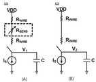
도 6내지 도 8을 참조하면, 각 센서 저항부(121) 및 더미저항부(122)는 각각 제1 전압-시간 변환부(131) 및 제2 전압-시간 변환부(132)에 연결될 수 있으며, 제1 전압-시간 변환부(131)는 온도 센서와 연결된 라인과 연결될 수 있고, 제2 전압-시간 변환부(132)는 센서가 없는 더미 라인과 연결 될 수 있다.6 to 8, each of the
각각의 회로 구성에 따라, 각각의 제1 전압-시간 변환부(131) 및 제2 전압-시간 변환부(132)는 클럭으로 인해 스위치가 꺼지고 방전이 시작된 시간 이후로부터 T1만큼의 시간 후에 도 8(A)의 전압 파형이 출력되며, T2만큼의 시간 후에 도 8(B)의 전압 파형이 출력될 수 있다.According to each circuit configuration, each of the first voltage-
이에 따라, T1과 T2의 크기가 앞서 수학식 2에서 개시된 값으로 지정될 있다. 시간차 연산부(133)는 이 두 시간의 차이인 T0를 연산하여, 온도 정보를 포함하는 시간 신호를 생성할 수 있다. 수학식 2에서 Tth는 캐패시터에 저장된 전압이 떨어지다가 인버터의 한계(threshold) 전압보다 아래로 떨어진 순간에 인버터의 출력에서 상승 펄스(rising pulse)가 생성되기 때문에 그 한계(threshold)만큼의 시간을 나타내며, 시간차 연산부(133) 이를 연산하여 제외시킬 수 있다.Accordingly, the magnitudes of T1 and T2 may be designated as the values described in Equation (2). The
이와 같이, 본 발명의 실시 예에 따른 온도 측정 장치(100)는 센서 저항부(121) 출력에서 더미저항부(122) 출력을 제외시켜 줌으로써, 센서와 회로를 이어주는 금속 선(metal wire)의 저항성분을 제거할 뿐만 아니라, 수학식 2에서와 같이, T1과 T2을 유도하는 과정에서 나타나는 다른 여러가지 offset term들을 모두 제거할 수 있게 된다. 따라서, 본 발명의 실시 예에 따른 온도 측정 장치(100)는 VDD와 Is가 불안정하더라도, 이에 영향받지 않고 정확한 시간 신호를 생성할 수 있게 한다.As described above, the temperature measuring apparatus 100 according to the embodiment of the present invention excludes the output of the
한편, 데이터 변환부(130)는 TDC(Time to digital converter)를 더 포함할 수 있다. TDC는 온도에 따라 변하지 않고 일정하게 동작할 수 있으며, 온도 정보를 포함하는 시간 신호를 디지털 신호로 변환하여 출력할 수 있다.Meanwhile, the
제어부(110)는 이와 같이 생성된 온도 정보에 기초하여 온도변화에 따른 저항 특성이 반영된 온도 값을 결정할 수 있다. 이를 위해, 제어부(110)는 각 센서에 대응되는 출력 테이블을 저장할 수 있다. 또한, 제어부(110)는 출력 테이블을 생성하기 위한 캘리브레이션을 더 수행할 수 있으며, 이에 대하여는 도 10 및 도 11에서 보다 상세히 설명하도록 한다.The
도 9는 본 발명의 실시 예에 따른 온도 측정 방법을 설명하기 위한 흐름도이다.9 is a flowchart for explaining a temperature measurement method according to an embodiment of the present invention.
도 9를 참조하면, 본 발명의 실시 예에 따른 온도 측정 장치(100)는, 먼저 온도 측정 장치(100)에 전원을 인가한다(S101).Referring to FIG. 9, the temperature measuring apparatus 100 according to the embodiment of the present invention first applies power to the temperature measuring apparatus 100 (S101).
전원부(111)는 제어부(110)의 제어에 의해 온도 측정 장치(100)의 동작을 위한 클럭 구동 전원 및 인가 전압(VDD) 등을 전반적인 온도 측정 장치(100)의 각각의 구성 요소로 인가할 수 있다.The
그리고, 본 발명의 실시 예에 따른 온도 측정 장치(100)는 전원이 인가되면, 선서 선택을 위한 클럭 신호를 입력한다(S103).When the power is applied, the temperature measuring apparatus 100 according to the embodiment of the present invention inputs a clock signal for selecting a swipe (S103).
제어부(110)는 특정 센서 저항부(120)를 선택하기 위한 클럭 신호를 생성하여, 선택 대상 센서 저항부(121)의 스위치로 인가할 수 있다.The
그리고, 온도 측정 장치(100)는 선택된 센서 저항부(121)에 포함된 캐패시터에 전하를 충전한다(S105).Then, the temperature measuring apparatus 100 charges the capacitor included in the selected sensor resistance unit 121 (S105).
전원부(111)로부터 공급되는 전류는 제어부(110)에서 제어되는 스위치에 의해, 센서 저항부(121)에 포함된 캐패시터로 공급될 수 있다.The current supplied from the
이후, 선택 클럭 신호가 해제되면 온도 측정 장치(100)는 충전된 캐패시터의 전하를 방전한다(S107).Thereafter, when the selected clock signal is released, the temperature measuring apparatus 100 discharges the charge of the charged capacitor (S107).
전술한 바와 같이, 클럭 신호 해제에 의한 스위치 제어에 의해 전원 인가가 차단되면, 센서 저항부(121)에 포함된 캐패시터는 직렬연결된 전류 소스(Is)의 동작에 의해 일정한 속도로 방전될 수 있다. 이 때, 더미저항부(122)에서는 센서 저항부(121)에 전원이 인가되는 동일한 시점에 동일한 충전 및 방전 동작을 수행할 수 있다. 그러나, 센서 저항부(121)에 포함된 센서 저항 자체의 특성에 의해 더미저항부(122)와 센서 저항부(121)의 시간당 전압 변화는 상이할 수 있다.As described above, when the power supply is cut off by the switch control by the release of the clock signal, the capacitor included in the
이에 따라, 온도 측정 장치(100)는 방전에 의해 발생되는 센서 저항부(121)의 한계(threshold) 전압 이상 값의 출력 시간 및 더미저항부(122)의 한계(threshold) 전압 이상 값의 출력 시간 간 시간 차를 연산한다(S109).Accordingly, the temperature measuring apparatus 100 measures the output time of the threshold voltage or more of the
전술한 바와 같이, 센서 저항부(121)에 포함된 센서 저항은 온도 특성에 따라 서로 다른 계수값을 갖는 선형적 특성을 가질 수 있다. 이와 같은 선형적 특성을 추출하기 위해, 시간차 연산부(133)는 도 8에 도시된 바와 같이, 센서 저항부(121)의 한계(threshold) 전압 이상 값의 출력 시간 및 더미저항부(122)의 한계(threshold) 전압 이상 값의 출력 시간 간 시간 차를 연산하여 그 결과값으로 TO라는 시간 전압 파형을 획득할 수 있다.As described above, the sensor resistance included in the
마지막으로, 온도 측정 장치(100)는 연산된 시간차에 기초하여 온도 값을 결정하고(S111), 외부로 출력한다.Finally, the temperature measuring apparatus 100 determines a temperature value based on the calculated time difference (S111) and outputs it to the outside.
먼저 데이터 변환부(130)의 시간-디지털 변환부(134)는 시간 전압 파형에 기초하여 디지털 변환된 시간 값을 획득하고, 제어부(110)로 전달할 수 있다. 그리고, 제어부(110)는 디지털 변환된 시간 값에 기초하여 온도 계수를 획득할 수 있으며, 미리 저장된 출력 테이블에 기초하여 측정 대상의 현재 온도를 획득하여 다른 마이크로 시스템 또는 외부로 출력할 수 있다.The time-to-
한편, 이와 같은 출력 테이블을 생성하기 위해, 제어부(110)는 캘리브레이션 과정을 수행할 수 있다.Meanwhile, in order to generate such an output table, the
도 10 및 도 11은 본 발명의 다른 일 실시 예에 따른 온도 측정 장치의 캘리브레이션 방법을 설명하기 위한 도면들이다.10 and 11 are views for explaining a calibration method of a temperature measuring apparatus according to another embodiment of the present invention.
보다 구체적으로, 온도 측정 장치(100)가 실제 반도체 ? 위에 구현되어 온도 센서로서의 역하을 수행하기 위하여는, 실제적인 온도 측정 장치(100)의 출력 대비 온도 값을 결정할 수 있는 출력 테이블이 존재할 필요성이 있다. 그러나, 각각의 센서 저항에 대하여 모든 방식의 출력 테이블을 생성하기에는 실용적이지 않은 측면이 존재한다.More specifically, when the temperature measuring apparatus 100 is an actual semiconductor? It is necessary to have an output table for determining the output temperature value of the actual temperature measuring apparatus 100 in order to perform the reversing as the temperature sensor. However, there are aspects that are impractical to generate output tables of all types for each sensor resistance.
따라서, 본 발명의 실시 예에 따른 온도 측정 장치(100)는 적어도 2개의 지점에 대한 캘리브레이션만을 수행함으로써 출력 테이블을 미리 생성하는 기능을 제공할 수 있다.Therefore, the temperature measuring apparatus 100 according to the embodiment of the present invention can provide a function of generating an output table in advance by performing only calibration for at least two points.
이를 위해, 본 발명의 실시 예에 따른 온도 측정 장치(100)는 센서 저항이 아닌 캘리브레이션을 위한 제1 저항(센서 저항과 저항 값 및 종류가 동일한 저항) 및 이와 상이한 제2 저항을 온도 측정 장치(100)가 설치된 칩의 적어도 2 이상의 위치에 형성할 수 있다.To this end, the temperature measuring apparatus 100 according to the embodiment of the present invention includes a first resistor (a resistance having the same resistance value and the same type as the sensor resistance) for calibrating rather than a sensor resistance, and a second resistor different from the first resistor 100 can be formed on at least two or more positions of the chip.
이와 같은 제1 저항 및 제2 저항은 하나의 캘리브레이션 세트로 호칭할 수 있다. 이와 같은 캘리브레이션 세트의 구조는 도 10에 도시된 바와 같이 예시될 수 있다. 캘리브레이션 세트는 제1 저항(201) 및 제2 저항(202)을 포함하여 온도 측정 장치(100)의 제어부(110)와 연결될 수 있다.Such a first resistor and a second resistor may be referred to as one calibration set. The structure of such a calibration set can be illustrated as shown in FIG. The calibration set may include a first resistor 201 and a
앞서 설명한 수학식 2의 최종 출력 식을 참조하면, 선형 특성을 갖는 저항의 최종 출력은 온도에 대해 선형적인 직선의 식으로 표현됨을 알 수 있다. 따라서, 적어도 2개의 점의 위치를 알거나, 한 개의 점의 위치를 알고 그 기울기를 파악하면 다른 지점의 온도 값을 모두 추정할 수 있다.Referring to the final output equation of Equation (2) described above, it can be seen that the final output of a resistor having a linear characteristic is represented by a linear linear equation with respect to temperature. Therefore, by knowing the positions of at least two points, or knowing the position of one point and grasping the slope, it is possible to estimate all the temperature values at other points.
이에 따라, 본 발명의 실시 예에 따른 제어부(110)는 직선의 식을 완성하기 위해, 적어도 항상 2 지점의 온도에 대한 출력 값 측정을 통해 선형 계수를 추정함으로서, 다른 지점에 대한 캘리브레이션 필요 없이도 캘리브레이션을 완료시킬 수 있다.Accordingly, in order to complete the equation of the straight line, the
예를 들어, 본 발명의 실시 예에 따른 온도 측정 장치(100)는 반도체 칩이 최초 제작되는 시점에, 상술한 본 발명의 실시 예에 따른 캘리브레이션을 적어도 2 이상의 지점에 대하여 수행함으로써, 수학식 2에 대응되는 TC(Temperature Coefficient)의 값을 추정할 수 있다.For example, the temperature measuring apparatus 100 according to the embodiment of the present invention can perform the calibration according to the embodiment of the present invention at the time when the semiconductor chip is initially manufactured, The value of the TC (Temperature Coefficient) corresponding to the temperature can be estimated.
그리고, 온도 측정 장치(100)는 미리 추정된 TC값을 다른 지점에 위치한 모든 센서 저항에 적용할 수 있다. 따라서, 온도 측정 장치(100)는 실제 센서로서 동작하는 경우 1 지점의 온도에 대해서만 캘리브레이션을 진행하면 각 센서 저항별 출력에 대응되는 온도 값을 갖는 출력 테이블을 생성할 수 있다. 이에 제어부(110)는 생성된 출력 테이블을 별도 메모리 등의 저장 공간에 미리 저장할 수 있다.Then, the temperature measuring apparatus 100 can apply the previously estimated TC value to all the sensor resistances located at different points. Accordingly, when the temperature measuring apparatus 100 is operated as an actual sensor, the output table having the temperature value corresponding to the output of each sensor resistance can be generated by performing the calibration only for the temperature of the one point. The
결과적으로, 본 발명의 실시 예에 따른 온도 측정 장치(100)는 캘리브레이션 횟수를 효과적으로 줄이는 결과를 이끌어낼 수 있다.As a result, the temperature measuring apparatus 100 according to the embodiment of the present invention can lead to a result of effectively reducing the number of calibrations.
도 11은 본 발명의 실시 예에 따른 캘리브레이션 방법을 설명하기 위한 흐름도이다.11 is a flowchart illustrating a calibration method according to an embodiment of the present invention.
도 11을 참조하면, 본 발명의 실시 예에 따른 온도 측정 장치(100)는 캘리브레이션 세트를 식별하고(S201), 제1 지점의 온도에 대한 제1 캘리브레이션을 수행하며(S203), 제2 지점의 온도에 대한 제2 캘리브레이션을 수행한다(S205).Referring to FIG. 11, a temperature measuring apparatus 100 according to an embodiment of the present invention identifies a calibration set (S201), performs a first calibration for a temperature at a first point (S203) A second calibration for the temperature is performed (S205).
앞서 설명한 바와 같이, 제어부(110)는 적어도 2 이상의 캘리브레이션 세트를 식별하고, 각 캘리브레이션 세트로부터 측정되는 측정 결과에 기초하여 캘리브레이션을 수행할 수 있다.As described above, the
캘리브레이션 세트는 전술한 제1 저항(201) 및 제2 저항(202)을 포함할 수 있으며, 제1 저항(201)은 본 발명의 실시 예에 따른 센서 저항부(121)의 센서 저항과 동일한 값 및 동일한 종류를 가질 수 있다. 그리고, 제2 저항(202)은 상기 센서 저항과는 상이한 저항을 포함할 수 있으며, 전압에 따라 온도를 가변하는 히터(HEATER) 역할을 수행할 수 있다. 예를 들어, 제1 저항(201)은 메탈 소재의 저항일 수 있으며, 제2 저항(202)은 폴리(POLY)소재의 저항일 수 있다.The calibration set may include the first resistor 201 and the
이에 따라, 제어부(110)는 식별된 각 지점별 캘리브레이션 세트를 제어하여, 제1 지점의 온도에 대한 제1 캘리브레이션을 수행하고, 제2 지점의 온도에 대한 제2 캘리브레이션을 수행할 수 있다.Accordingly, the
이후, 온도 측정 장치(100)는 제1 지점 및 제2 지점에 대한 캘리브레이션 수행 결과에 기초하여 온도 계수값을 산출한다(S207).Thereafter, the temperature measuring apparatus 100 calculates a temperature coefficient value based on a result of performing the calibration with respect to the first point and the second point (S207).
앞서 설명한 수학식 2와 같이, 2 지점에 대한 캘리브레이션이 수행되면 각 센서 저항에 대한 온도 변수로서, 온도 계수값 TC가 산출될 수 있다. 이는 제어부(110)의 제어에 의해 수행될 수 있다.When the calibration for two points is performed as shown in
그리고, 온도 측정 장치(100)는 온도 계수값을 이용하여 다른 일 지점에 대한 캘리브레이션을 수행한다(S209).Then, the temperature measuring apparatus 100 performs calibration for another point using the temperature coefficient value (S209).
앞서 설명한 바와 같이, 제어부(110)는 수학식 2에 기초하여, 미리 산출된 온도 계수값 TC가 존재하는 경우, 다른 지점의 실제 센서 저항부(121)의 센서 저항에 대한 캘리브레이션을 수행할 수 있게 된다. 이에 따라, 제어부(110)는 각 센서 저항부(121)의 온도 대비 출력 테이블을 생성할 수 있으며, 별도 저장 공간에 미리 저장할 수 있다.As described above, the
이를 위해, 제어부(110)는 별도의 저장부 등에 연결될 수 있으며, 저장부는 예를 들어, 제어부(110)의 동작을 위한 프로그램을 저장할 수 있고, 입/출력되는 데이터들을 임시 저장할 수도 있다. 저장부는 플래시 메모리 타입(flash memory type), 하드디스크 타입(hard disk type), 멀티미디어 카드 마이크로 타입(multimedia card micro type), 카드 타입의 메모리(예를 들어 SD 또는 XD 메모리 등), 램(Random Access Memory, RAM), SRAM(Static Random Access Memory), 롬(Read-Only Memory, ROM), EEPROM(Electrically Erasable Programmable Read-Only Memory), PROM(Programmable Read-Only Memory), 자기 메모리, 자기 디스크, 광디스크 중 적어도 하나의 타입의 저장매체를 포함할 수 있다.For this purpose, the
한편, 상술한 본 발명의 다양한 실시 예들에 따른 전자 장치의 제어 방법은 프로그램 코드로 구현되어 다양한 비일시적 판독 가능 매체(non-transitory computer readable medium)에 저장된 상태로 각 서버 또는 기기들에 제공될 수 있다.Meanwhile, the method of controlling an electronic device according to various embodiments of the present invention described above may be implemented in program code and provided to each server or devices in a state stored in various non-transitory computer readable media have.
비일시적 판독 가능 매체란 레지스터, 캐쉬, 메모리 등과 같이 짧은 순간 동안 데이터를 저장하는 매체가 아니라 반영구적으로 데이터를 저장하며, 기기에 의해 판독(reading)이 가능한 매체를 의미한다. 구체적으로는, 상술한 다양한 어플리케이션 또는 프로그램들은 CD, DVD, 하드 디스크, 블루레이 디스크, USB, 메모리카드, ROM 등과 같은 비일시적 판독 가능 매체에 저장되어 제공될 수 있다.A non-transitory readable medium is a medium that stores data for a short period of time, such as a register, cache, memory, etc., but semi-permanently stores data and is readable by the apparatus. In particular, the various applications or programs described above may be stored on non-volatile readable media such as CD, DVD, hard disk, Blu-ray disk, USB, memory card, ROM,
또한, 이상에서는 본 발명의 바람직한 실시예에 대하여 도시하고 설명하였지만, 본 발명은 상술한 특정의 실시예에 한정되지 아니하며, 청구범위에서 청구하는 본 발명의 요지를 벗어남이 없이 당해 발명이 속하는 기술분야에서 통상의 지식을 가진자에 의해 다양한 변형실시가 가능한 것은 물론이고, 이러한 변형실시들은 본 발명의 기술적 사상이나 전망으로부터 개별적으로 이해되어져서는 안될 것이다.While the present invention has been particularly shown and described with reference to exemplary embodiments thereof, it is to be understood that the invention is not limited to the disclosed exemplary embodiments, but, on the contrary, It will be understood by those skilled in the art that various changes in form and detail may be made therein without departing from the spirit and scope of the present invention.
Claims (20)
Translated fromKorean적어도 하나의 센서 저항을 포함하고, 동작 전압이 인가되면 온도에 따라 상기 센서 저항에 의해 선형적으로 가변되는 센싱신호를 출력하는 센서부;
상기 센서부로부터 출력되는 센싱신호에 기초하여 측정된 온도 변화를 시간 신호로 변환하고, 변환된 시간 신호에 기초하여 온도 정보를 생성하는 데이터 변환부; 및
상기 센서부 및 상기 데이터 변환부를 제어하고, 상기 온도 정보에 따라 결정된 온도 값을 출력하는 제어부를 포함하고,
상기 센서부는
상기 센서 저항을 포함하며, 제1 선택 신호에 따라 상기 센서 저항에 의한 제1 신호를 출력하는 센서 저항부; 및
상기 센서 저항부의 회로 연결구조로부터 상기 센서 저항이 생략된 연결구조를 가지며, 제2 선택 신호에 따라 제2 신호를 출력하는 더미저항부를 포함하며,
상기 데이터 변환부는
상기 제1 신호의 전압에 따라 제1 시간 동안 한계 전압 이상 값을 출력하는 제1 전압-시간 컨버터;
상기 제2 신호의 전압에 따라 제2 시간 동안 상기 한계 전압 이상 값을 출력하는 위한 제2 전압-시간 컨버터; 및
상기 제1 전압-시간 컨버터 및 상기 제2 전압-시간 컨버터 출력의 상기 제1 시간 및 상기 제2 시간 간 시간차를 연산하는 시간차 연산부;를 포함하고,
상기 시간차 연산부로부터 출력되는 상기 시간차에 대응하는 시간 신호를 디지털 신호로 변환하여 출력하는 온도 독립적 TDC(Time to digital converter);를 더 포함하는 온도 측정 장치.A temperature measuring apparatus comprising:
A sensor unit including at least one sensor resistor and outputting a sensing signal linearly varied by the sensor resistance according to a temperature when an operating voltage is applied;
A data converter for converting a temperature change measured based on the sensing signal output from the sensor unit into a time signal and generating temperature information based on the converted time signal; And
And a control unit controlling the sensor unit and the data conversion unit and outputting a temperature value determined according to the temperature information,
The sensor unit
A sensor resistor including the sensor resistor and outputting a first signal by the sensor resistor according to a first selection signal; And
And a dummy resistor part having a connection structure in which the sensor resistor is omitted from the circuit connection structure of the sensor resistor part and outputting a second signal according to a second selection signal,
The data conversion unit
A first voltage-time converter for outputting an over-limit voltage value for a first time according to the voltage of the first signal;
A second voltage-time converter for outputting the limit voltage abnormality value for a second time according to the voltage of the second signal; And
And a time difference arithmetic unit for calculating a time difference between the first time and the second time of the first voltage-time converter and the second voltage-time converter output,
And a temperature-independent TDC (Time to Digital Converter) for converting a time signal corresponding to the time difference output from the time difference calculating unit into a digital signal and outputting the digital signal.
상기 더미저항부에서 출력되는 제2 신호는
상기 더미저항부에 포함된 선 저항에 의해 형성되는 신호 성분을 포함하는 것을 특징으로 하는
온도 측정 장치.The method according to claim 1,
And the second signal outputted from the dummy resistor section
And a signal component formed by the line resistance included in the dummy resistor portion
Temperature measuring device.
상기 제어부는 상기 디지털 변환된 시간 신호에 기초하여 온도 계수를 획득하고, 상기 온도 계수를 미리 저장된 출력 테이블과 비교하여 현재 온도를 획득하는 온도 측정 장치.The method according to claim 1,
Wherein the controller acquires a temperature coefficient based on the digitally converted time signal and compares the temperature coefficient with a pre-stored output table to obtain a current temperature.
상기 제어부는
상기 데이터 변환부 출력에 대응하여, 상기 온도 값을 결정하기 위한 온도 정보 테이블을 캘리브레이션하여 미리 저장하는
온도 측정 장치.The method according to claim 1,
The control unit
A temperature information table for determining the temperature value corresponding to the output of the data conversion unit is calibrated and stored in advance
Temperature measuring device.
상기 센서부는
상기 제어부의 제1 선택 신호가 인가되면 상기 센서 저항과 연결된 제1 캐패시터에 전하를 충전하고,
상기 선택 신호가 해제된 시점부터 상기 제1 캐패시터로부터 전하가 방전되면서 상기 한계 전압 이상으로 유지되는 상기 제1 시간 동안 제1 전압을 출력하는
온도 측정 장치.The method according to claim 1,
The sensor unit
When a first selection signal of the controller is applied, charges are charged in a first capacitor connected to the sensor resistor,
The first capacitor is discharged from the time when the selection signal is released, and the first voltage is output during the first time period in which the voltage is maintained above the threshold voltage
Temperature measuring device.
상기 센서부는
상기 제어부의 제2 선택 신호가 인가되면 상기 센서 저항과 연결되지 않은 제2 캐패시터에 전하를 충전하고,
상기 선택 신호가 해제된 시점부터 상기 제2 캐패시터로부터 전하가 방전되면서 상기 한계전압 이상으로 유지되는 상기 제2 시간 동안 제2 전압을 출력하는
온도 측정 장치.8. The method of claim 7,
The sensor unit
When the second selection signal of the control unit is applied, charging the second capacitor not connected to the sensor resistor,
The second capacitor is discharged from the time when the selection signal is released, and the second voltage is output during the second time period when the selection signal is released,
Temperature measuring device.
상기 데이터 변환부는 상기 제1 전압 및 상기 제2 전압의 출력 시간 차이에 기초하여 상기 온도 정보를 생성하는 온도 측정 장치.10. The method of claim 9,
Wherein the data conversion unit generates the temperature information based on an output time difference between the first voltage and the second voltage.
동작 전압이 인가되면, 적어도 하나의 센서 저항으로부터 온도에 따라 상기 센서 저항에 의해 가변 측정되는 센싱신호를 출력하는 단계;
상기 센싱신호에 기초하여 측정된 온도 변화를 시간 신호로 변환하고, 상기 시간 신호에 기초하여 온도 정보를 생성하는 단계; 및
상기 온도 정보에 따라 결정된 온도 값을 출력하는 단계를 포함하고,
상기 센싱신호를 출력하는 단계는,
상기 동작 전압 인가에 따라, 센서 저항부에서 상기 센서 저항에 의한 제1 신호를 출력하는 단계; 및
상기 동작 전압 인가에 따라, 상기 센서 저항부의 회로 연결구조로부터 상기 센서 저항이 생략된 연결구조를 가지는 더미저항부에서 제2 신호를 출력하는 단계를 포함하고,
상기 온도 정보를 생성하는 단계는,
제1 전압-시간 컨버터에서 상기 제1 시간 동안 한계 전압 이상 값을 출력하는 단계;
제2 전압-시간 컨버터에서 상기 제2 시간 동안 상기 한계 전압 이상 값을 출력하는 단계; 및
상기 제1 전압-시간 컨버터 및 상기 제2 전압-시간 컨버터 출력의 상기제1 시간 및 상기 제2 시간 간 시간차를 연산하는 단계를 포함하고,
TDC(Time to digital converter)를 통해 상기 시간차에 대응하는 시간 신호를 디지털 신호로 변환하여 출력하는 단계를 더 포함하는 온도 측정 방법.In the temperature measuring method,
Outputting a sensing signal variable-measured by the sensor resistor according to a temperature from at least one sensor resistor when an operating voltage is applied;
Converting the measured temperature change based on the sensing signal into a time signal and generating temperature information based on the time signal; And
And outputting a temperature value determined according to the temperature information,
The step of outputting the sensing signal includes:
Outputting a first signal by the sensor resistor in the sensor resistor portion according to the application of the operating voltage; And
And outputting a second signal in a dummy resistor portion having a connection structure in which the sensor resistor is omitted from the circuit connection structure of the sensor resistor portion in accordance with application of the operating voltage,
Wherein the step of generating the temperature information comprises:
Outputting a threshold voltage value for the first time in the first voltage-time converter;
Outputting the limit voltage abnormality value for the second time in a second voltage-time converter; And
Time converter, and calculating a time difference between the first time and the second time of the first voltage-time converter and the second voltage-time converter output,
And converting the time signal corresponding to the time difference to a digital signal through a time to digital converter (TDC) and outputting the digital signal.
상기 제2 신호는
더미저항부에 포함된 선 저항에 의해 형성되는 신호 성분을 포함하는 것을 특징으로 하는
온도 측정 방법.12. The method of claim 11,
The second signal
And a signal component formed by a line resistance included in the dummy resistor portion
Method of measuring temperature.
상기 온도 정보에 대응하여, 상기 온도 값을 결정하기 위한 온도 정보 테이블을 캘리브레이션하여 미리 저장하는 단계를 더 포함하는
온도 측정 방법.12. The method of claim 11,
And calibrating and preliminarily storing a temperature information table for determining the temperature value corresponding to the temperature information
Method of measuring temperature.
상기 센싱신호를 출력하는 단계는,
상기 센서 저항을 선택하기 위한 제1 선택 신호가 인가되면 상기 센서 저항과 연결된 제1 캐패시터에 전하를 충전하는 단계; 및
상기 제1 선택 신호가 해제된 시점부터 상기 제1 캐패시터로부터 전하가 방전되면서 상기 한계 전압 이상으로 유지되는 제1 시간 동안 제1 전압을 출력하는 단계를 포함하는
온도 측정 방법.12. The method of claim 11,
The step of outputting the sensing signal includes:
Charging a first capacitor coupled to the sensor resistor when a first select signal for selecting the sensor resistor is applied; And
And outputting a first voltage during a first time period during which the charge is discharged from the first capacitor at a time point when the first selection signal is released and is maintained above the threshold voltage
Method of measuring temperature.
상기 센싱신호를 출력하는 단계는,
제2 선택 신호가 인가되면 상기 센서 저항과 연결되지 않은 제2 캐패시터에 전하를 충전하는 단계; 및
상기 제2 선택 신호가 해제된 시점부터 상기 제2 캐패시터로부터 전하가 방전되면서 상기 한계 전압으로 유지되는 제2 시간 동안 제2 전압을 출력하는 단계를 포함하는
온도 측정 방법.18. The method of claim 17,
The step of outputting the sensing signal includes:
Charging a second capacitor not connected to the sensor resistor when a second selection signal is applied; And
And outputting a second voltage for a second time period during which the charge is discharged from the second capacitor from the time when the second selection signal is released to be maintained at the threshold voltage
Method of measuring temperature.
Priority Applications (2)
| Application Number | Priority Date | Filing Date | Title |
|---|---|---|---|
| KR1020140069269AKR101615435B1 (en) | 2014-06-09 | 2014-06-09 | An appratus for sensing temperature using a sensor resistor and a method thereof |
| US14/733,527US9915569B2 (en) | 2014-06-09 | 2015-06-08 | Apparatus for sensing temperature using sensor resistor and method thereof |
Applications Claiming Priority (1)
| Application Number | Priority Date | Filing Date | Title |
|---|---|---|---|
| KR1020140069269AKR101615435B1 (en) | 2014-06-09 | 2014-06-09 | An appratus for sensing temperature using a sensor resistor and a method thereof |
Related Child Applications (1)
| Application Number | Title | Priority Date | Filing Date |
|---|---|---|---|
| KR1020140069280ADivisionKR101549341B1 (en) | 2014-06-09 | 2014-06-09 | An appratus for sensing temperature using a sensor resistor and a method thereof |
Publications (2)
| Publication Number | Publication Date |
|---|---|
| KR20150141227A KR20150141227A (en) | 2015-12-18 |
| KR101615435B1true KR101615435B1 (en) | 2016-04-26 |
Family
ID=54769350
Family Applications (1)
| Application Number | Title | Priority Date | Filing Date |
|---|---|---|---|
| KR1020140069269AExpired - Fee RelatedKR101615435B1 (en) | 2014-06-09 | 2014-06-09 | An appratus for sensing temperature using a sensor resistor and a method thereof |
Country Status (2)
| Country | Link |
|---|---|
| US (1) | US9915569B2 (en) |
| KR (1) | KR101615435B1 (en) |
Families Citing this family (8)
| Publication number | Priority date | Publication date | Assignee | Title |
|---|---|---|---|---|
| US9400511B1 (en)* | 2016-01-07 | 2016-07-26 | International Business Machines Corporation | Methods and control systems of resistance adjustment of resistors |
| CN105910726B (en)* | 2016-06-29 | 2019-06-25 | 江南大学 | A kind of hardware nonlinearity compensation method of platinum resistor temperature measuring |
| KR102533348B1 (en)* | 2018-01-24 | 2023-05-19 | 삼성전자주식회사 | Temperature sensing device and temperature-voltage converter |
| EP3978937A4 (en)* | 2019-05-27 | 2022-06-22 | Guangdong Oppo Mobile Telecommunications Corp., Ltd. | Temperature measurement method and apparatus, and storage medium |
| DE102019123582B3 (en)* | 2019-09-03 | 2020-11-12 | Infineon Technologies Ag | DEVICE AND METHOD FOR INSPECTING AT LEAST ONE SOLDER CONNECTION BETWEEN A CIRCUIT BOARD AND A CURRENT SENSOR |
| CN113945293B (en) | 2020-06-30 | 2023-04-18 | 长鑫存储技术有限公司 | Semiconductor device with a plurality of semiconductor chips |
| DE102020215326A1 (en)* | 2020-12-03 | 2022-06-09 | Robert Bosch Gesellschaft mit beschränkter Haftung | Method for determining a cable and/or connector temperature on an electric drive |
| CN118794566B (en)* | 2024-09-13 | 2024-11-22 | 南昌三盛半导体有限公司 | A quality assessment method and system for platinum thin film temperature sensor |
Family Cites Families (21)
| Publication number | Priority date | Publication date | Assignee | Title |
|---|---|---|---|---|
| US4050309A (en)* | 1974-11-04 | 1977-09-27 | William Wahl Corporation | Method and apparatus for measuring temperature |
| US4065715A (en)* | 1975-12-18 | 1977-12-27 | General Motors Corporation | Pulse duration modulated signal transducer |
| US4206648A (en)* | 1979-02-26 | 1980-06-10 | Rca Corporation | Impedance measuring circuit |
| GB2157515B (en)* | 1984-02-01 | 1987-10-07 | Suwa Seikosha Kk | Electronic thermometer |
| US4703886A (en)* | 1985-12-06 | 1987-11-03 | Chris Kirby | Heat/cool comfort controller |
| US4910689A (en)* | 1986-12-25 | 1990-03-20 | Canon Kabushiki Kaisha | Resistivity value measuring circuit |
| JP3352793B2 (en) | 1993-11-18 | 2002-12-03 | 株式会社チノー | Temperature measuring device |
| JPH07159460A (en)* | 1993-12-07 | 1995-06-23 | Toshiba Corp | Resistance sensor input device |
| EP0701687B1 (en)* | 1994-04-05 | 1999-07-28 | Koninklijke Philips Electronics N.V. | Resistance measuring circuit, and thermal appliance, electrical thermometer and cold-generating appliance including such a measuring circuit |
| US6320512B1 (en)* | 2000-11-03 | 2001-11-20 | Larry Nicholson | Temperature monitor for temperature sensitive products |
| US6824307B2 (en)* | 2000-12-12 | 2004-11-30 | Harris Corporation | Temperature sensor and related methods |
| CN1329719C (en)* | 2000-12-12 | 2007-08-01 | 迷你米特公司 | Digital Sensors and Body Temperature Monitors for Tiny Medical Thermometers |
| US6957910B1 (en)* | 2004-01-05 | 2005-10-25 | National Semiconductor Corporation | Synchronized delta-VBE measurement system |
| US8182139B2 (en)* | 2008-05-30 | 2012-05-22 | Apple Inc. | Calibration of temperature sensing circuitry in an electronic device |
| JP5215060B2 (en)* | 2008-07-02 | 2013-06-19 | テルモ株式会社 | Electronic thermometer and operation control method |
| KR101081366B1 (en)* | 2009-09-23 | 2011-11-08 | 포항공과대학교 산학협력단 | A time-domain voltage comparator for analog digital converter |
| JP5383610B2 (en)* | 2010-08-17 | 2014-01-08 | パナソニック株式会社 | A / D converter |
| JP5684076B2 (en)* | 2011-09-06 | 2015-03-11 | 株式会社日立製作所 | Analog to digital converter and radio receiver |
| KR101283998B1 (en)* | 2012-03-23 | 2013-07-10 | 포항공과대학교 산학협력단 | A time difference amplifier and amplification method using slew rate control |
| US9488530B2 (en)* | 2013-10-23 | 2016-11-08 | National Kaohsiung First University Of Science And Technology | Time-domain temperature sensing system with a digital output and method thereof |
| JP2016225951A (en)* | 2015-06-03 | 2016-12-28 | 株式会社東芝 | Amplifier circuit and analog/digital conversion circuit |
- 2014
- 2014-06-09KRKR1020140069269Apatent/KR101615435B1/ennot_activeExpired - Fee Related
- 2015
- 2015-06-08USUS14/733,527patent/US9915569B2/ennot_activeExpired - Fee Related
Also Published As
| Publication number | Publication date |
|---|---|
| US9915569B2 (en) | 2018-03-13 |
| KR20150141227A (en) | 2015-12-18 |
| US20150355034A1 (en) | 2015-12-10 |
Similar Documents
| Publication | Publication Date | Title |
|---|---|---|
| KR101615435B1 (en) | An appratus for sensing temperature using a sensor resistor and a method thereof | |
| KR100949271B1 (en) | Temperature information sensing device suitable for auto self refresh, having integrated circuit and temperature information sensing method | |
| US9813063B2 (en) | Method of using a field-effect transistor as a current sensing device | |
| CN108507699B (en) | Method for estimating surface temperature of portable device and portable device | |
| JP4942990B2 (en) | Semiconductor memory device | |
| TWI424441B (en) | Temperature sensing system and related temperature sensing method | |
| US20120268995A1 (en) | Non-volatile semiconductor memory device and electronic apparatus | |
| US11499874B2 (en) | Temperature sensor including diode and capacitor | |
| US10378969B2 (en) | Temperature sensor | |
| KR20140146711A (en) | Semiconductor memory device and semiconductor package | |
| US20180052506A1 (en) | Voltage and frequency scaling apparatus, system on chip and voltage and frequency scaling method | |
| US9645016B2 (en) | Temperature sensor | |
| JP5359886B2 (en) | Temperature measuring apparatus and method | |
| KR20160060556A (en) | Remaining battery life prediction device and battery pack | |
| JP2008060884A (en) | Semiconductor integrated circuit | |
| US10915257B2 (en) | Semiconductor device and semiconductor system | |
| US7610165B2 (en) | Semiconductor memory device having on die thermal sensor | |
| US10197455B2 (en) | Thermal oscillator | |
| KR101549341B1 (en) | An appratus for sensing temperature using a sensor resistor and a method thereof | |
| JP6313150B2 (en) | Semiconductor device, battery monitoring system, and battery monitoring method | |
| CN105280216B (en) | Semiconductor memory device and method of operating the same | |
| CN103035281A (en) | Temperature control self-refreshing method based on unit electric leakage detection | |
| US8922408B2 (en) | Semiconductor device | |
| KR102739824B1 (en) | Semiconductor device including temperature sensing circuit | |
| KR20150051471A (en) | Semiconductor device and method of driving the same |
Legal Events
| Date | Code | Title | Description |
|---|---|---|---|
| A107 | Divisional application of patent | ||
| A201 | Request for examination | ||
| PA0107 | Divisional application | St.27 status event code:A-0-1-A10-A18-div-PA0107 St.27 status event code:A-0-1-A10-A16-div-PA0107 | |
| PA0109 | Patent application | St.27 status event code:A-0-1-A10-A12-nap-PA0109 | |
| PA0201 | Request for examination | St.27 status event code:A-1-2-D10-D11-exm-PA0201 | |
| PN2301 | Change of applicant | St.27 status event code:A-3-3-R10-R13-asn-PN2301 St.27 status event code:A-3-3-R10-R11-asn-PN2301 | |
| R18-X000 | Changes to party contact information recorded | St.27 status event code:A-3-3-R10-R18-oth-X000 | |
| E902 | Notification of reason for refusal | ||
| PE0902 | Notice of grounds for rejection | St.27 status event code:A-1-2-D10-D21-exm-PE0902 | |
| E13-X000 | Pre-grant limitation requested | St.27 status event code:A-2-3-E10-E13-lim-X000 | |
| P11-X000 | Amendment of application requested | St.27 status event code:A-2-2-P10-P11-nap-X000 | |
| P13-X000 | Application amended | St.27 status event code:A-2-2-P10-P13-nap-X000 | |
| E90F | Notification of reason for final refusal | ||
| PE0902 | Notice of grounds for rejection | St.27 status event code:A-1-2-D10-D21-exm-PE0902 | |
| P11-X000 | Amendment of application requested | St.27 status event code:A-2-2-P10-P11-nap-X000 | |
| P13-X000 | Application amended | St.27 status event code:A-2-2-P10-P13-nap-X000 | |
| PG1501 | Laying open of application | St.27 status event code:A-1-1-Q10-Q12-nap-PG1501 | |
| E701 | Decision to grant or registration of patent right | ||
| PE0701 | Decision of registration | St.27 status event code:A-1-2-D10-D22-exm-PE0701 | |
| GRNT | Written decision to grant | ||
| PR0701 | Registration of establishment | St.27 status event code:A-2-4-F10-F11-exm-PR0701 | |
| PR1002 | Payment of registration fee | St.27 status event code:A-2-2-U10-U11-oth-PR1002 Fee payment year number:1 | |
| PG1601 | Publication of registration | St.27 status event code:A-4-4-Q10-Q13-nap-PG1601 | |
| FPAY | Annual fee payment | Payment date:20190402 Year of fee payment:4 | |
| PR1001 | Payment of annual fee | St.27 status event code:A-4-4-U10-U11-oth-PR1001 Fee payment year number:4 | |
| R18-X000 | Changes to party contact information recorded | St.27 status event code:A-5-5-R10-R18-oth-X000 | |
| PC1903 | Unpaid annual fee | St.27 status event code:A-4-4-U10-U13-oth-PC1903 Not in force date:20200420 Payment event data comment text:Termination Category : DEFAULT_OF_REGISTRATION_FEE | |
| PN2301 | Change of applicant | St.27 status event code:A-5-5-R10-R13-asn-PN2301 St.27 status event code:A-5-5-R10-R11-asn-PN2301 | |
| R18-X000 | Changes to party contact information recorded | St.27 status event code:A-5-5-R10-R18-oth-X000 | |
| PC1903 | Unpaid annual fee | St.27 status event code:N-4-6-H10-H13-oth-PC1903 Ip right cessation event data comment text:Termination Category : DEFAULT_OF_REGISTRATION_FEE Not in force date:20200420 | |
| R18-X000 | Changes to party contact information recorded | St.27 status event code:A-5-5-R10-R18-oth-X000 | |
| R18-X000 | Changes to party contact information recorded | St.27 status event code:A-5-5-R10-R18-oth-X000 |