KR101610186B1 - Dust collector of vacuum cleaner having a function of removing dust detached from filter - Google Patents
Dust collector of vacuum cleaner having a function of removing dust detached from filterDownload PDFInfo
- Publication number
- KR101610186B1 KR101610186B1KR1020090073101AKR20090073101AKR101610186B1KR 101610186 B1KR101610186 B1KR 101610186B1KR 1020090073101 AKR1020090073101 AKR 1020090073101AKR 20090073101 AKR20090073101 AKR 20090073101AKR 101610186 B1KR101610186 B1KR 101610186B1
- Authority
- KR
- South Korea
- Prior art keywords
- filter
- dust
- unit
- centrifugal separator
- collecting apparatus
- Prior art date
- Legal status (The legal status is an assumption and is not a legal conclusion. Google has not performed a legal analysis and makes no representation as to the accuracy of the status listed.)
- Active
Links
Images


Classifications
- A—HUMAN NECESSITIES
- A47—FURNITURE; DOMESTIC ARTICLES OR APPLIANCES; COFFEE MILLS; SPICE MILLS; SUCTION CLEANERS IN GENERAL
- A47L—DOMESTIC WASHING OR CLEANING; SUCTION CLEANERS IN GENERAL
- A47L9/00—Details or accessories of suction cleaners, e.g. mechanical means for controlling the suction or for effecting pulsating action; Storing devices specially adapted to suction cleaners or parts thereof; Carrying-vehicles specially adapted for suction cleaners
- A47L9/10—Filters; Dust separators; Dust removal; Automatic exchange of filters
- A47L9/12—Dry filters
- A—HUMAN NECESSITIES
- A47—FURNITURE; DOMESTIC ARTICLES OR APPLIANCES; COFFEE MILLS; SPICE MILLS; SUCTION CLEANERS IN GENERAL
- A47L—DOMESTIC WASHING OR CLEANING; SUCTION CLEANERS IN GENERAL
- A47L9/00—Details or accessories of suction cleaners, e.g. mechanical means for controlling the suction or for effecting pulsating action; Storing devices specially adapted to suction cleaners or parts thereof; Carrying-vehicles specially adapted for suction cleaners
- A47L9/10—Filters; Dust separators; Dust removal; Automatic exchange of filters
- A47L9/16—Arrangement or disposition of cyclones or other devices with centrifugal action
- A47L9/1658—Construction of outlets
- A47L9/1666—Construction of outlets with filtering means
- A—HUMAN NECESSITIES
- A47—FURNITURE; DOMESTIC ARTICLES OR APPLIANCES; COFFEE MILLS; SPICE MILLS; SUCTION CLEANERS IN GENERAL
- A47L—DOMESTIC WASHING OR CLEANING; SUCTION CLEANERS IN GENERAL
- A47L9/00—Details or accessories of suction cleaners, e.g. mechanical means for controlling the suction or for effecting pulsating action; Storing devices specially adapted to suction cleaners or parts thereof; Carrying-vehicles specially adapted for suction cleaners
- A47L9/10—Filters; Dust separators; Dust removal; Automatic exchange of filters
- A47L9/16—Arrangement or disposition of cyclones or other devices with centrifugal action
- A47L9/1683—Dust collecting chambers; Dust collecting receptacles
- A—HUMAN NECESSITIES
- A47—FURNITURE; DOMESTIC ARTICLES OR APPLIANCES; COFFEE MILLS; SPICE MILLS; SUCTION CLEANERS IN GENERAL
- A47L—DOMESTIC WASHING OR CLEANING; SUCTION CLEANERS IN GENERAL
- A47L9/00—Details or accessories of suction cleaners, e.g. mechanical means for controlling the suction or for effecting pulsating action; Storing devices specially adapted to suction cleaners or parts thereof; Carrying-vehicles specially adapted for suction cleaners
- A47L9/20—Means for cleaning filters
- B—PERFORMING OPERATIONS; TRANSPORTING
- B01—PHYSICAL OR CHEMICAL PROCESSES OR APPARATUS IN GENERAL
- B01D—SEPARATION
- B01D45/00—Separating dispersed particles from gases or vapours by gravity, inertia, or centrifugal forces
- B01D45/12—Separating dispersed particles from gases or vapours by gravity, inertia, or centrifugal forces by centrifugal forces
- B—PERFORMING OPERATIONS; TRANSPORTING
- B01—PHYSICAL OR CHEMICAL PROCESSES OR APPARATUS IN GENERAL
- B01D—SEPARATION
- B01D46/00—Filters or filtering processes specially modified for separating dispersed particles from gases or vapours
- B01D46/24—Particle separators, e.g. dust precipitators, using rigid hollow filter bodies
- B01D46/2403—Particle separators, e.g. dust precipitators, using rigid hollow filter bodies characterised by the physical shape or structure of the filtering element
- B01D46/2411—Filter cartridges
- B—PERFORMING OPERATIONS; TRANSPORTING
- B01—PHYSICAL OR CHEMICAL PROCESSES OR APPARATUS IN GENERAL
- B01D—SEPARATION
- B01D46/00—Filters or filtering processes specially modified for separating dispersed particles from gases or vapours
- B01D46/42—Auxiliary equipment or operation thereof
- B01D46/48—Removing dust other than cleaning filters, e.g. by using collecting trays
- B—PERFORMING OPERATIONS; TRANSPORTING
- B01—PHYSICAL OR CHEMICAL PROCESSES OR APPARATUS IN GENERAL
- B01D—SEPARATION
- B01D46/00—Filters or filtering processes specially modified for separating dispersed particles from gases or vapours
- B01D46/52—Particle separators, e.g. dust precipitators, using filters embodying folded corrugated or wound sheet material
- B01D46/521—Particle separators, e.g. dust precipitators, using filters embodying folded corrugated or wound sheet material using folded, pleated material
- B—PERFORMING OPERATIONS; TRANSPORTING
- B01—PHYSICAL OR CHEMICAL PROCESSES OR APPARATUS IN GENERAL
- B01D—SEPARATION
- B01D46/00—Filters or filtering processes specially modified for separating dispersed particles from gases or vapours
- B01D46/66—Regeneration of the filtering material or filter elements inside the filter
- B01D46/74—Regeneration of the filtering material or filter elements inside the filter by forces created by movement of the filter element
- B01D46/76—Regeneration of the filtering material or filter elements inside the filter by forces created by movement of the filter element involving vibrations
- B—PERFORMING OPERATIONS; TRANSPORTING
- B01—PHYSICAL OR CHEMICAL PROCESSES OR APPARATUS IN GENERAL
- B01D—SEPARATION
- B01D50/00—Combinations of methods or devices for separating particles from gases or vapours
- B01D50/20—Combinations of devices covered by groups B01D45/00 and B01D46/00
- B—PERFORMING OPERATIONS; TRANSPORTING
- B01—PHYSICAL OR CHEMICAL PROCESSES OR APPARATUS IN GENERAL
- B01D—SEPARATION
- B01D2279/00—Filters adapted for separating dispersed particles from gases or vapours specially modified for specific uses
- B01D2279/55—Filters adapted for separating dispersed particles from gases or vapours specially modified for specific uses for cleaning appliances, e.g. suction cleaners
Landscapes
- Chemical & Material Sciences (AREA)
- Chemical Kinetics & Catalysis (AREA)
- Engineering & Computer Science (AREA)
- Mechanical Engineering (AREA)
- Physics & Mathematics (AREA)
- Geometry (AREA)
- Filters For Electric Vacuum Cleaners (AREA)
Abstract
Translated fromKoreanDescription
Translated fromKorean본 발명은 필터부재에 포집된 먼지를 제거하고, 필터부재에서 분리된 필터먼지를 자동으로 제거하는 기능을 가지는 진공청소기의 집진장치에 관한 것이다.The present invention relates to a dust collecting apparatus for a vacuum cleaner having a function of removing dust collected on a filter member and automatically removing filter dust separated from the filter member.
먼지 봉투 교체의 번거로움 및 비용 부담을 해소하기 위하여 부압에 의해 유입된 먼지를 분리하는 원심분리기(사이클론, cyclone)와 원심분리기에서 분리된 먼지를 수납하는 먼지통 및 먼지가 분리된 공기에 포함된 미세 이물질을 걸러내는 필터(2차 필터라 함)를 포함하는 집진장치를 구비한 원심분리형(사이클론형) 진공청소기가 널리 보급되었다.(Cyclone) separating the dust introduced by the negative pressure and the dust bin containing the separated dust from the centrifuge and the fine dust contained in the separated air in order to solve the troubles of the dust bag replacement and the cost burden A centrifugal separator (cyclone type) vacuum cleaner having a dust collecting device including a filter (hereinafter referred to as a secondary filter) for filtering foreign matter has been widely popularized.
상술한 구성을 가지는 종래기술의 집진장치의 경우 2차 필터에 미세 먼지가 누적되면 흡입력이 떨어져 청소면의 이물질의 흡입 및 원심분리기 내부에서의 먼지 분리가 원활하지 않게 되는 문제점을 가진다.In the case of the conventional dust collecting apparatus having the above-described configuration, when fine dust accumulates in the secondary filter, the suction force is reduced and suction of foreign matter on the clean surface and dust separation in the centrifugal separator are not smooth.
이에 따라 2차 필터에 누적된 먼지를 제거하기 위한 다양한 종래기술이 개시 되어 있다.Accordingly, various conventional techniques for removing dust accumulated in the secondary filter are disclosed.
상술한 종래기술들의 예로는 일본 등록특허 소48-10345호(종래기술 1) 및 대한민국 등록특허 제804568호(종래기술 2) 등에 개시된 진공청소기 등에 개시된 진공청소기들을 들 수 있다.Examples of the above-mentioned prior arts include vacuum cleaners disclosed in Japanese Patent Application No. 48-10345 (Prior Art 1) and Korean Patent No. 804568 (Prior Art 2), etc., and the like.
상기 종래기술 1은 제진부에 의해 2차 필터에 포집된 먼지를 떨어내는 구조를 개시한다. 상기 2차 필터로부터 분리된 먼지는 먼지통에 형성되는 연락공과 외기를 흡입하는 통기공 사이를 연결하는 별도의 유로에 수집된다. 이에 의해 진공청소기가 구동되면 통기공을 통해 유입되는 외부 공기에 의해 2차 필터로부터 분리된 먼지를 연락공을 통해 먼지통의 내부로 수집한다.The above-mentioned prior art 1 discloses a structure in which dust collected in the secondary filter is removed by a dust-removing portion. The dust separated from the secondary filter is collected in a separate flow passage connecting between the communication hole formed in the dust container and the air hole for sucking the outside air. Accordingly, when the vacuum cleaner is driven, the dust separated from the secondary filter is collected into the dust container through the communication hole by the outside air introduced through the vent hole.
그러나 상기 종래기술 1의 경우에는 2차 필터에서 분리된 먼지를 먼지통으로 유입시키기 위한 별도의 유로를 구성하므로, 먼지통의 구조가 복잡해지며, 압력손실이 발생하는 문제점을 가진다. 또한, 진공청소기의 압력 손실 저하를 위해 연락공과 통기공을 연결하는 별도의 유로의 크기가 제한되므로 2차 필터에서 분리된 먼지가 용이하게 제거되지 못하는 문제점을 가진다.However, in the case of the prior art 1, since the dust separated from the secondary filter is configured as a separate flow path for introducing the dust into the dust box, the structure of the dust box is complicated and pressure loss is generated. In addition, since the size of a separate flow path connecting the communication hole and the vent hole is limited in order to lower the pressure loss of the vacuum cleaner, the dust separated from the secondary filter can not be easily removed.
종래기술 2의 경우에는 2차 필터에서 분리된 먼지를 별도의 저장 공간에 저장하게 된다. 이 경우 별도의 저장 공간은 그 부피가 작아 수집된 먼지를 자주 비워야 하므로 사용상의 불편함을 발생시킨다.In the case of the prior art 2, the dust separated from the secondary filter is stored in a separate storage space. In this case, the separate storage space is small in volume, and the collected dust often needs to be emptied, resulting in inconvenience in use.
또한, 종래기술들의 경우 집진장치의 각 구성의 분리가 용이하지 않아 수리, 교체 등의 관리가 어려운 문제점을 가진다.In addition, in the related art, separation of each constitution of the dust collecting apparatus is not easy, and there is a problem that it is difficult to manage repair, replacement, and the like.
따라서 상술한 종래기술의 문제점을 해결하기 위한 본 발명은, 필터부재에서 제거된 필터먼지를 자동으로 하나의 먼지통으로 이동시켜 원심분리부에서 분리된 먼지와 함께 비울 수 있도록 하는 진공청소기의 집진장치를 제공하는 것을 목적으로 한다.SUMMARY OF THE INVENTION Accordingly, the present invention has been made keeping in mind the above problems occurring in the prior art, and it is an object of the present invention to provide a dust collecting apparatus for a vacuum cleaner that automatically removes filter dust removed from a filter member to one dust container, The purpose is to provide.
또한, 본 발명은 필터부재가 재오염되는 것을 방지하는 진공청소기의 집진장치를 제공하는 것을 다른 목적으로 한다.It is another object of the present invention to provide a dust collecting apparatus for a vacuum cleaner which prevents the filter member from being re-contaminated.
또한, 본 발명은 집진장치의 각 구성의 청소, 수리, 교체 등의 관리를 용이하게 하는 진공청소기의 집진장치를 제공하는 것을 또 다른 목적으로 한다.It is still another object of the present invention to provide a dust collecting apparatus for a vacuum cleaner which facilitates the cleaning, repairing, and replacement of each constitution of the dust collecting apparatus.
상기 목적을 달성하기 위한 본 발명의 제진 기능을 가지는 진공청소기의 집진장치는, 원심분리부; 상기 원심분리부에서 분리된 먼지를 수집하는 먼지통; 상기 원심분리부에서 유입된 공기에 포함된 먼지를 필터부재에 의해 분리하고, 상기 필터부재에 포집된 필터먼지를 분리하여 상기 원심분리부의 상류(전류) 측으로 이동시키는 필터부;를 포함하여 구성되는 것을 특징으로 한다.According to another aspect of the present invention, there is provided a dust collecting apparatus for a vacuum cleaner having a dust collecting function, including: a centrifugal separator; A dust container for collecting dust separated by the centrifugal separator; And a filter unit that separates the dust contained in the air introduced from the centrifugal separator by the filter member and separates the filter dust collected in the filter member and moves the filter dust to the upstream side (current) side of the centrifugal separator .
본 발명은 또한, 상기 필터부에 설치되어 상기 필터먼지를 상기 원심분리부의 상류로 강제이동시키는 먼지배출부재를 더 포함하여 구성될 수 있다.The present invention may further comprise a dust discharging member installed on the filter unit for forcibly moving the filter dust upstream of the centrifugal separator.
상기 필터부는, 상기 원심분리부의 상류 측과 연통하는 필터먼지배출구멍이 형성된 필터케이스; 상기 필터케이스 내에 설치되어 공기에 포함된 먼지를 제거하는 필터유닛; 상기 필터유닛의 회전 시 상기 필터부재에 포집된 필터먼지를 떨어내는 제진부; 및, 상기 필터부재에서 분리된 필터먼지를 상기 필터먼지배출구멍을 통해 상기 원심분리부의 상류로 이동시키는 먼지배출부재;를 포함하여 구성될 수 있다.Wherein the filter unit comprises: a filter case having a filter dust outlet hole communicating with an upstream side of the centrifugal separator; A filter unit installed in the filter case to remove dust contained in the air; A damping unit for damping filter dust collected on the filter member when the filter unit rotates; And a dust discharging member for moving the filter dust separated from the filter member to the upstream side of the centrifugal separating unit through the filter dust discharging hole.
상기 제진부는 고정되어 있고, 상기 필터유닛은 회전되어 상기 필터부재에 묻은 상기 필터먼지를 분리하도록 구성될 수 있다.The damping portion is fixed, and the filter unit may be configured to rotate and separate the filter dust adhering to the filter member.
상기 필터유닛과 상기 먼지배출부재는 서로 연동되어 같이 회전되도록 구성될 수 있다.The filter unit and the dust discharging member may be configured to rotate in conjunction with each other.
상기 필터케이스는, 상기 필터먼지배출구멍과 연통하는 상기 먼지배출부재의 상부면에서 상기 필터먼지배출구멍 및 상기 필터케이스와 연통하는 상기 먼지배출부재의 영역을 차폐하도록 돌출 형성되는 차폐턱을 더 포함하여 구성될 수 있다.The filter case further includes a shielding protrusion protruding from an upper surface of the dust discharging member communicating with the filter dust discharging hole so as to shield the filter dust discharging hole and the region of the dust discharging member communicating with the filter case .
상기 필터유닛은 상기 먼지배출부재와 일체로 회전되는 필터안착부재;를 더 포함하고, 상기 제진부는 상기 필터부재의 내부면과 접촉되도록 설치되도록 구성될 수 있다.The filter unit may further include a filter seat member rotated integrally with the dust discharging member, and the dust removing unit may be configured to be installed in contact with the inner surface of the filter member.
상기 먼지배출부재는, 상기 필터유닛의 저면에 결합되어 날개 사이 영역을 형성하는 다수의 날개를 포함하여 구성될 수 있다.The dust discharging member may include a plurality of blades coupled to a bottom surface of the filter unit to form an area between the blades.
상기 먼지배출부재는 또한, 상기 필터유닛의 저면에 방사상으로 결합되어 다수의 날개 사이 영역을 형성하는 다수의 날개를 포함하여 구성되어, 상기 필터유닛과 함께 회전하면서 상기 필터먼지를 상기 필터먼지배출구멍으로 이동시키도록 구 성될 수 있다. 이를 위해 상기 먼지배출부재는 외주 면에 방사상으로 상기 날개들이 형성되는 날개관; 및 상기 날개관의 상부면에 돌출 형성되는 다수의 날개돌기;를 포함하여 구성될 수 있다. 상기 먼지배출부재가 회전하는 때에 상기 날개들이 형성하는 날개 사이 영역 중 적어도 하나는 상기 필터먼지배출구멍의 상부에 위치되어 상기 원심분리부의 상류 측과 연통한다.Wherein the dust drain member further comprises a plurality of vanes radially coupled to the bottom surface of the filter unit to form a plurality of vanes between the vanes, As shown in FIG. To this end, the dust discharging member includes a blade opening formed radially on the outer circumferential surface thereof; And a plurality of blade protrusions protruding from an upper surface of the blade opening. At least one of the areas between the wings formed by the vanes when the dust discharging member rotates is located at the upper portion of the filter dust discharging hole and communicates with the upstream side of the centrifugal separating unit.
상기 먼지통은 상기 집진장치와 착탈 가능하게 형성될 수 있다.The dust container may be detachably attached to the dust collecting device.
상기 집진장치는 상기 상류 및 하류를 형성하는 상기 원심분리부와 상기 먼지통과 상기 필터부가 수평으로 병렬 배치되도록 구성될 수 있다.The dust collecting device may be configured such that the centrifugal separator, the dust container, and the filter part forming the upstream and downstream are arranged in parallel horizontally.
상기 집진장치는 또한, 하부 원심분리부와 하부 필터부와 상기 먼지통이 장착 또는 탈착되는 먼지통안착부가 일체로 형성된 흡배기유로부; 상기 하부 원심분리부의 상부에 결합하여 상기 원심분리부를 형성하는 상부 원심분리부; 상기 하부 필터부의 상부에 결합하여 상기 필터부를 형성하는 상부 필터부; 및, 상기 먼지통안착부에 장착 또는 탈착되는 먼지통;으로 분리 구성될 수 있다.The dust collecting apparatus may further include a suction and discharge channel unit having a lower centrifugal separator, a lower filter unit, and a dust receptacle for mounting or dismounting the dust receptacle integrally formed therein; An upper centrifugal part coupled to an upper part of the lower centrifugal part to form the centrifugal part; An upper filter unit coupled to an upper portion of the lower filter unit to form the filter unit; And a dust container which is attached to or detached from the dust container receiving portion.
상기 상부 원심분리부와 상기 상부 필터부는 일체형으로 형성될 수 있다.The upper centrifugal separator and the upper filter may be integrally formed.
상술한 본 발명은 필터부재로부터 분리된 필터먼지를 원심분리부의 상류로 이동시키는 것에 의해 진공청소기의 구동 시 필터먼지가 먼지통으로 수집되도록 함으로써 필터먼지를 먼지통의 먼지와 동시에 배출할 수 있도록 하는 사용상의 편리성을 제공한다.The present invention is characterized in that the filter dust separated from the filter member is moved to the upstream side of the centrifugal separator to collect the filter dust into the dust container when the vacuum cleaner is driven so that the filter dust can be discharged simultaneously with the dust of the dust container. Provide convenience.
또한, 본 발명은 필터부재로부터 분리된 먼지가 먼지통에 수집되도록 하여 분리된 필터먼지에 의해 필터부재가 재오염되는 것을 방지한다.Further, according to the present invention, the dust separated from the filter member is collected in the dust container, thereby preventing the filter member from being re-contaminated by the separated filter dust.
또한, 본 발명은 원심분리부와 먼지통과 필터부가 수평으로 병렬 배치됨으로써 집진장치의 높이를 최소화하여, 집진장치 및 진공청소기의 크기를 줄일 수 있도록 한다.In addition, since the centrifugal separator, the dust container, and the filter unit are horizontally disposed in parallel, the height of the dust collector is minimized, thereby reducing the size of the dust collector and the vacuum cleaner.
또한, 본 발명은 먼지배출부재로 인해서 필터먼지 이동의 신뢰성을 확보할 수 있다.Further, in the present invention, reliability of movement of the filter dust can be secured by the dust discharging member.
또한, 본 발명은 집진장치의 각 구성의 분리 구조에 의해 집진장치의 관리를 용이하게 한다.Further, the present invention facilitates the management of the dust collecting apparatus by the separated structure of each constitution of the dust collecting apparatus.
이하, 본 발명의 실시 예를 나타내는 첨부 도면을 참조하여 본 발명을 더욱 상세히 설명한다.Hereinafter, the present invention will be described in more detail with reference to the accompanying drawings showing embodiments of the present invention.
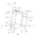
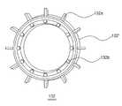
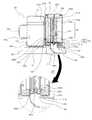
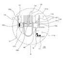
도 1은 본 발명의 실시 예에 따르는 집진장치(100)의 사시도, 도 2는 흡배기유로부(200)의 사시도, 도 3은 도 1의 III-III 선을 따라 절단한 후 III 방향으로 바라본 도 1의 집진장치(100)의 단면도, 도 4는 도 1의 IV-IV 선을 따라 절단한 후 IV 방향으로 바라본 도 1의 집진장치(100)의 단면도, 도 5는 필터유닛(131)의 저면 사시도, 도 6은 먼지배출부재(132)의 평면 사시도, 도 7은 도 1의 VII-VII 선을 따라 절단한 후 VII 방향으로 바라본 도 1의 집진장치(100)의 단면도이다.Fig. 1 is a perspective view of the
상기 집진장치(100)(도 1 참조)는 수평 방향으로 병렬 배치된 원심분리부(110), 먼지통(120) 및 필터부(130)를 포함하여 구성된다.1) includes a
상기 원심분리부(110)는 서로 분리되고 결합되는 상부 원심분리부(110a)와 하부 원심분리부(210)로 구성된다.The
상기 필터부(130) 또한, 서로 분리되고 결합되는 상부 필터부(130')와 하부 필터부(230)로 구성된다.The
도 2와 같이, 상기 하부 원심분리부(210)와 상기 하부 필터부(230)는 측부가 서로 연결되며, 하부 원심분리부(210)와 하부 필터부(230)의 결합부위의 측면으로 먼지통안착부(220)가 연결 형성된 일체형의 흡배기유로부(200)를 이룬다.2, the lower
상기 하부 원심분리부(210)는 안정기(112b), 가이드(112c) 및 흡입관(111)을 포함하여 구성된다.The lower
상기 하부 필터부(230)의 필터부배기구(139a)를 이루는 필터부배기관(139)의 상부 면에는 일정 간격으로 하부고정부재지지돌기홈(139c)이 형성되고, 내부에는 배기그릴(139b)이 형성된다.A lower fixing member supporting
상기 하부 필터부(230)의 상기 하부 원심분리부(210)와 대향하는 위치의 저면에는 하부 필터부(230)와 상기 원심분리부(110)의 상류를 이루는 흡입관(111)을 서로 연통시키는 필터먼지배출구멍(140)이 관통 형성된다(도 2 참조).A
상기 구성에서 상기 상부 원심분리부(110a)가 상기 하부 원심분리부(210)의 상부에 결합되고, 상기 상부 필터부(130')가 상기 하부 필터부(230)의 상부에 결합되며, 상기 먼지통안착부(220)에 상기 먼지통(120)이 장착되는 것에 의해 도 1의 일체형의 집진장치(100)로 결합된다.The upper
상기 원심분리부(110)(도 3 참조)는 흡입관(111), 안정기(112b), 가이드(112c), 원심분리부배기관(112) 및 내부 영역을 상부는 배기유로(112a)로 하부는 원심분리영역(110c)으로 분리하는 분리벽(110b)을 포함하여 구성된다. 이때 상기 흡입관(111)과 안정기(112b)는 하부 원심분리부(210)를 형성하고, 상기 원심분리부배기관(112)과 분리벽(110b) 및 배기유로(112a)는 상부 원심분리부(110a)를 형성한다.3) includes a
상기 흡입관(111)은 상기 원심분리부(110)의 저면에서 원심분리영역(110c)과 연통되게 형성된다. 상기 흡입관(111)의 원심분리영역(110c)과 결합하는 내부영역은 상기 필터부(130)에 형성되는 필터먼지배출구멍(140)(도 4 참조)을 통해 배출된 필터먼지(10)(도 8 및 도 9 참조)가 수집되는 필터먼지수집영역(111a)이 된다.The
상기 안정기(112b)는 상기 원심분리부배기관(112)과 서로 마주하는 단면이 동일 축 상에 위치되도록 상기 원심분리영역(110c)의 내부 저면에서 상 방향으로 돌출 형성된다.The
상기 가이드(112c)는 상기 안정기(112b)의 외주면을 따라 나선형을 이루며 형성되어 흡입관(111)을 통해 유입된 공기가 원심분리영역(110c) 내부에서 회전하며 상 방향으로 이동하는 것을 유도한다.The
상기 원심분리부배기관(112)은 상기 분리벽(110b)의 저면 중앙에서 하 방향으로 돌출 형성되어 원심분리영역(110c)과 배기유로(112a)을 연통시킨다.The
상기 원심분리영역(110c)의 상부 측면에는 회전하는 공기로부터 원심력에 의해 분리된 먼지를 먼지통(120)으로 배출하도록 먼지통(120)과 연통하는 먼지배출구(121)가 형성된다.A
상기 배기유로(112a)는 원심분리부(110)의 상부 내부 영역에 형성되어 원심분리영역(110c)에서 배출된 공기를 필터부유입구(130d)(도 4 참조)를 통해 필터부(130)로 유입시키도록 구성된다. 상기 배기유로(112a)를 상기 분리벽(110b)에 의해 원심분리영역(110c)과 분리벽(110b)에 의해 분리시킨 것은, 원심분리영역(110c) 내에서의 공기가 원활히 회전하도록 하며, 회전하는 공기에 포함된 크고 무거운 먼지가 필터부(130)로 유입되는 것을 방지하기 위함이다.The
상기 먼지통(120)은 먼지 배출을 위해 개폐 가능하게 결합되는 상부 먼지통커버(122)와 먼지수집영역(120a)에 먼지를 저장하는 하부먼지통(123)(도 3 참조)을 포함하여 구성된다. 상기 먼지통(120)은 상기 먼지배출구(121)를 통해 상기 원심분리부(110)와 연통하며, 상기 먼지통안착부(220)에 착탈 가능하도록 분리 구성된다. 상기 먼지통(120)의 착탈을 위해 상기 먼지통(120)의 외부면에는 먼지통손잡이(124)가 형성된다. 이와 달리, 상기 먼지통(120)은 상기 원심분리부(110)에 고정결합되도록 구성될 수도 있다.The
상기 필터부(130)(도 4 참조)는, 필터케이스(130a), 필터케이스커버(130b),필터유닛(131), 제진부(150) 및 먼지배출부재(132)를 포함하는 상부 필터부(130') 와 필터부배기관(139)을 포함하는 하부 필터부(230)로 구성된다.4) includes a
상기 필터케이스(130a)는 상부에 배기유로(112a)와 연통하는 필터부유입구(130d)가 형성된다. 상기 필터케이스(130a)의 저면 중앙에는 상기 필터부재(131a)에 의해 미세먼지가 분리된 공기가 배출되도록 외부와 연통하는 필터부배기관(139)이 형성된다. 상기 원심분리부(110) 측의 상기 필터케이스(130a) 내부의 저면에는 상기 원심분리부(110)의 상류부인 필터먼지수집영역(111a)과 연통하는 필터먼지배출구멍(140)이 형성된다. 상기 필터먼지배출구멍(140)의 상부에 위치되는 필터케이스(130a)의 내부 면에는 날개 사이 영역(132c)(도 6 참조)을 필터케이스(130a) 내부 영역과 차폐하기 위해 필터케이스(130a)의 내부로 일정 길이 돌출되는 차폐턱(141)이 형성된다.The
상기 필터케이스커버(130b)는 상기 필터케이스(130a)의 상부에 개폐 가능하며, 회전 가능하게 결합된다. 상기 필터케이스커버(130b)는 또한, 상부에 제진손잡이(134)가 형성되며, 저면에는 필터부재(131a)의 상부 단면이 결합하도록 구성된다. 이러한 구성의 필터케이스커버(130b)는 제진을 위한 회전력을 필터유닛(131)으로 제공한다. 상기 필터케이스커버(130b)는 사용자에 의해 회전되는 것으로 설명되었으나 회전력을 제공하는 기어장치, 모터 등이 연결 구성되어 모터에 의해 회전되도록 구성될 수도 있다.The
상기 필터유닛(131)은 상기 필터케이스커버(130b)의 저면에 부착되는 필터부재(131a)와 상기 필터부재(131a)를 상기 필터케이스(130a)의 내부에서 회전 가능하게 지지하는 필터안착부재(131c)를 포함하여 구성된다. 상기 구성에서 상기 필터부 재(131a)의 저면이 상기 필터안착부재(131c)의 상부면에 결합되어 필터유닛(131)을 형성한다.The
상기 필터부재(131a)는 중앙에 필터중공부(131b)가 형성되도록 원통형 구조로 형성된다. 이러한 필터부재(131a)는 미세 기공이 형성된 발포수지 부재, 플리츠 부재 등으로 형성될 수 있다.The
상기 필터안착부재(131c)는 중앙이 필터중공부(131b) 및 필터부배기구(139a)와 연통하도록 관통된 환형 구조로 형성되어 상부면이 상기 필터부재(131a)의 저면에 고정 부착된다.The
상기 필터안착부재(131c)의 저면에(도 5 참조)는 방사상으로 다수의 날개돌기홈(131d)이 형성된다. 상기 날개돌기홈(131d)에는 하기에 설명될 먼지배출부재(132)의 날개돌기(132b)가 각각 삽입결합된다.A plurality of
상기 제진부(150)(도 4 및 도 5 참조)는 제진판(151)과, 상부 지지대(152a), 하부 지지대(152b) 및 하부 고정부재(136b)를 포함하여 구성된다.4 and 5) includes a
상기 제진판(151)은 상기 필터부재(131a)의 필터중공부(131b)에서 측면이 필터부재(131a)의 내부 측면과 접촉되도록 설치된다.The
상기 상부 지지대(152a)는 상기 제진판(151)과 제진판(151)의 상부를 지지하며 필터케이스커버(130b)가 회전될 수 있도록 필터케이스커버(130b)의 저면에 형성된 상부고정부(136a)에 결합된다.The
상기 하부 지지대(152b)는 상기 상부 지지대(152a) 및 상기 제진판(151)의 하부를 회전되지 않도록 고정하기 위해 하단부가 하부 고정부재(136b)에 고정된다.The
상기 하부 고정부재(136b)는 내부 중공부에 중심이 결합되어 방사상으로 연장되는 다수의 지지대로 이루어지는 지지프레임(136d)이 형성된 환형 구조로 형성된다. 상기 지지프레임(136d)의 중심에는 상기 하부 지지대(152b)의 하단부가 고정 결합된다.The
또한, 상기 하부 고정부재(136b)의 외주 연에는 다수의 하부고정부재지지돌기(136c)가 서로 일정 간격을 이루는 방사상으로 돌출 형성된다. 상기 하부고정부재지지돌기(136c)들은 상기 필터부배기관(139)의 상부면에 형성되는 하부고정부재지지돌기홈(139c)에 삽입되어(도 2 참조) 고정됨으로써 제진부(150)를 회전하지 않도록 고정한다.In addition, a plurality of lower fixing
상기 먼지배출부재(132)(도 6 참조)는 외주연에 다수의 날개(132a)가 방사상으로 형성되고, 상부면에는 상기 날개돌기홈(131d)(도 5 참조)에 삽입되는 다수의 날개돌기(132b)가 형성된 원통형의 날개관(132')으로 형성된다.6) has a plurality of
상기 필터부(130)의 결합 구조를 설명한다.The coupling structure of the
상기 먼지배출부재(132)는 상기 필터부배기구(139a)를 이루는 필터부배기관(139)의 상단부 외주 연에 결합된다. 이때 날개(132a)들이 형성하는 날개 사이 영역(132c) 중 하나가 상기 필터먼지배출구멍(140)(도 4 참조)과 연통하게 된다.The
상기 하부 고정부재(136b)는 상기 필터부배기관(139)의 상부 면에 안착된다. 이때 하부 고정부재(136b)가 필터유닛(131)의 회전에 따라 회전하지 않도록 하부 고정부재(136b)의 외주 연에 형성된 하부고정부재지지돌기(136c)들이 필터부배기관(139)의 상부면에 형성된 하부고정부재지지돌기홈(139c)(도 2 참조)에 각각 삽입된다.The
상기 하부 고정부재(136b)가 상기 필터부배기관(139)의 상부면에 안착된 후 상기 필터유닛(131)이 상기 필터중공부(131b)가 필터부배기구(139a)와 연통하도록 상기 먼지배출부재(132)의 상부면에 결합된다. 이때 상기 필터유닛(131)의 회전에 따라 상기 먼지배출부재(132)가 회전될 수 있도록 상기 먼지배출부재(132)의 상부면에 형성된 날개돌기(132b)들이 상기 필터부배기관(139)의 저면에 형성되는 날개돌기홈(131d)들에 삽입된다.After the
상기 제진부(150)는 필터중공부(131b)로 삽입되면서 제진판(151)의 측면은 필터부재(131a)의 내측 면과 접촉되고, 하부 지지대(152b)의 하단부는 하부 고정부재(136b)(도 7 참조)에 고정결합된다.The side surface of the
상기와 같이 결합된 상태에서 필터케이스커버(130b)가 필터케이스(130a)의 상부에 회전 가능하게 결합되면, 상기 필터부재(131a)의 상부면이 상기 필터케이스커버(130b)의 저면에 결합되고, 상기 제진부(150)의 상부 지지대(152a)의 상단부는 필터케이스커버(130b)의 저면에 형성된 상부고정부(136a)에 결합된다.When the
상술한 결합에 의해 상기 필터케이스커버(130b)가 회전하는 경우, 제진부(150)는 고정된 상태를 유지하며, 필터유닛(131)과 먼지배출부재(132)는 필터케이스커버(130b)와 함께 회전한다. 상기 필터유닛(131)의 회전은 종래기술에서 공지된 바와 같이 모터에 의해 수행될 수도 있다.When the
이하, 상기 집진장치(100)의 기능을 설명한다.Hereinafter, functions of the
상기 구조의 집진장치(100)가 진공청소기(미 도시)에 장착된 후 진공청소기가 동작하면 먼지 등의 이물질을 포함하는 외부 공기가 흡입관(111)을 통해 원심분리부(110)의 원심분리영역(110c)으로 유입된다.When the vacuum cleaner is operated after the
상기 원심분리영역(110c)의 내부로 유입된 공기는 안정기(112b)와 원심분리부배기관(112)을 중심으로 회전되고, 회전에 따라 발생하는 원심력에 의해 크고 무거운 먼지를 포함하는 이물질이 분리된다.The air introduced into the
상기 원심분리영역(110c)에서 분리된 먼지 등의 이물질은 먼지배출구(121)를 통해 먼지통(120)으로 배출된다.The foreign matter such as dust separated from the
상기 원심분리영역(110c) 내에서 회전에 의해 이물질이 분리된 공기는 원심분리부배기관(112), 배기유로(112a) 및 필터부유입구(130d)를 통해 필터부(130)로 유입된다.The air separated from the
상기 필터부(130)로 유입된 공기는 필터부재(131a)의 외부에서 필터중공부(131b)로 유입된다. 이 과정에서 가볍고 작은 미세 먼지를 포함하는 이물질들이 필터부재(131a)에 의해 걸러진다.The air introduced into the
상기 필터부재(131a)에 의해 미세 이물질이 걸러진 공기는 필터중공부(131b)의 하부로 이동하여 상기 필터부배기구(139a) 및 필터부배기관(139)을 통해 후류(하류)를 형성하며 집진장치(100)의 외부로 배출된다.The air filtered by the
상술한 바와 같은 진공청소기의 동작이 계속되어 배기가 원활하지 않을 정도로 상기 필터부재(131a)에 미세 먼지가 누적되면, 사용자는 제진부(150)를 이용하여 필터부재(131a)에 포집된 필터먼지(10)를 필터부재(131a)로부터 분리할 수 있다.If the vacuum cleaner continues to operate and the fine dust accumulates on the
도 8은 필터부재(131a)의 제진과정을 설명하기 위한 필터부(130)의 수직 단면도이고, 도 9는 도 3의 IX 부분의 확대도로서, 도 8 및 도 9를 참조하여 상기 필터부재(131a)에 대한 제진과정 및 필터먼지(10)의 제거 과정을 설명한다.FIG. 8 is a vertical sectional view of a
상기 필터부재(131a)에 먼지가 과도하게 포집되어 배기가 원활하지 않게 되면, 사용자는 진공청소기의 동작 중이나 동작 정지 상태에서 제진손잡이(134)를 이용하여 필터케이스커버(130b)를 회전시킨다.When the dust is excessively collected in the
상기 필터케이스커버(130b)가 회전하면 필터케이스(130a) 내부에 설치된 필터유닛(131)이 회전한다. 이때 제진부(150)는 고정된 상태를 유지하게 되므로, 필터부재(131a)의 내부면과 접촉하는 제진판(151)의 측면이 필터부재(131a)와 충돌하면서 필터부재(131a)를 진동시켜 필터부재(131a)에 포집된 필터먼지(10)를 필터부재(131a)로부터 분리한다.When the
상기 제진판(151)에 의해 필터부재(131a)로부터 분리된 필터먼지(10)는 먼지배출부재(132)의 날개(132a)들이 형성하는 날개 사이 영역(132c)에 수집된다.The
상기 필터케이스커버(130b)의 회전에 따라 필터유닛(131)과 함께 먼지배출부재(132)가 회전하므로, 상기 날개 사이 영역(132c) 또한 먼지배출부재(132)의 회전에 따라 회전된다. 이때 회전하는 날개(132a)들이 날개 사이 영역(132c)에 수집된 필터먼지(10)를 쓸면서 이동시킨다.The dust-discharging
상기 먼지배출부재(132)의 회전에 의해 날개 사이 영역(132c)이 필터먼지배출구멍(140)의 상부에 위치하면 날개(132a)들에 의해 쓸리면서 이동된 필터먼지(10)들이 필터먼지배출구멍(140)을 통해 흡입관(111)의 필터먼지수집영역(111a)으로 배출된다.When the
상기와 같이 필터먼지수집영역(111a)으로 이동된 필터먼지(10)는 진공청소기의 구동 시 흡입되는 공기에 의해 원심분리영역(110c) 내부로 유입된 후 회전하는 공기로부터 분리되어 먼지배출구(121)를 통해 먼지통(120)으로 배출된다.As described above, the
이 과정에서 상기 차폐턱(141)은 필터먼지배출구멍(140)의 상부와 연통하는 날개 사이 영역(132c)의 상부를 필터부(130)와 차폐시켜 원심분리부(110)로 유입되는 상류 공기가 곧바로 필터부(130) 내부로 유입하는 것을 방지한다,The shielding
상기 동작을 수행하는 집진장치(100)는 별도의 외부 구성을 구비함이 없이 필터부재(131a)로부터 분리된 필터먼지(10)를 먼지통(120)에 수집할 수 있도록 하여 사용상의 편리성을 향상시킨다.The
또한, 상기 집진장치(100)는 원심분리부(110), 먼지통(120) 및 필터부(130)가 수평 방향으로 배치되므로 집진장치(100)의 높이를 최소화한다. 이에 따라 상기 집진장치(100)가 장착되는 진공청소기(미 도시)의 높이 또한 최소화시켜, 진공청소기를 소형화시킴은 물론, 무게 중심을 낮추어 진공청소기의 사용 안정성을 향상시킨다.The
또한, 상기 집진장치(100)는 상기 원심분리부(110), 필터부(130)가 각각 상부 및 하부 원심분리부(210), 상부 및 하부 필터부(230)로 분리 가능하게 구성되는 것에 의해 원심분리부(110)와 필터부(130)의 수리, 교체 및 관리를 용이하게 한다.Since the
또한, 상기 집진장치(100)는 상기 먼지통(120)이 착탈 가능하게 구성되는 것에 의해 상기 집진장치(100)가 진공청소기(미 도시)에 장착되는 경우 원심분리부(110)와 필터부(130)를 진공청소기로부터 분리함이 없이 먼지통(120) 만을 진공청소기로부터 분리하는 것을 가능하게 한다. 따라서 사용자가 먼지통(120)의 먼지를 비우고자 하는 경우 집진장치(100) 전체를 진공청소기로부터 분리함이 없이 먼지통(120)만을 분리하여 먼지를 비울 수 있다. 이는 사용자의 먼지 배출 과정을 용이하게 하여 진공청소기의 사용상의 편리성을 향상시킨다.When the
상술한 본 발명의 실시 예의 설명에서 상기 집진장치(100)에 구성되는 상기 원심분리부(110)가 수직형(트윈챔버(twin cahmber) 형)인 것으로 도시하였으나, 상기 원심분리부는 수평형(누운형)으로 구성될 수도 있다.Although the
또한, 상기 원심분리부(110)는 복수 개가 형성될 수도 있다.In addition, a plurality of the
또한, 상기 원심분리부(110)는 크고 무거운 먼지를 분리하는 주 원심분리부와 주 원심분리부에서 먼지가 분리된 공기에 포함되는 미세먼지 등을 제거하기 위한 다수의 보조원심분리부(미 도시)를 포함하여 구성될 수도 있다.In addition, the
상술한 본 발명의 집진장치는 직립형 진공청소기, 배낭형 진공청소기, 핸디 형 진공청소기 등의 모든 진공청소기에 다양하게 적용될 수 있다.The above-described dust collecting apparatus of the present invention can be variously applied to all vacuum cleaners such as an upright type vacuum cleaner, a backpack type vacuum cleaner, and a handy type vacuum cleaner.
본 발명은 산업용, 가정용, 업소용 청소기 등의 청소기기에 적용될 수 있다.INDUSTRIAL APPLICABILITY The present invention can be applied to cleaning apparatuses for industrial use, household use, business cleaners, and the like.
도 1은 본 발명의 실시 예에 따르는 집진장치(100)의 사시도,1 is a perspective view of a
도 2는 흡배기유로부(200)의 사시도,2 is a perspective view of the intake and
도 3은 도 1의 III-III 선을 따라 절단한 후 III 방향으로 바라본 도 1의 집진장치(100)의 단면도,FIG. 3 is a cross-sectional view of the
도 4는 도 1의 IV-IV 선을 따라 절단한 후 IV 방향으로 바라본 도 1의 집진장치(100)의 단면도,FIG. 4 is a sectional view of the
도 5는 필터유닛(131)의 저면 사시도,5 is a bottom perspective view of the
도 6은 먼지배출부재(132)의 평면 사시도,6 is a planar perspective view of the
도 7은 도 1의 VII-VII 선을 따라 절단한 후 VII 방향으로 바라본 도 1의 집진장치(100)의 단면도,FIG. 7 is a sectional view of the
도 8은 필터부재(131a)의 제진과정을 설명하기 위한 필터부(130)의 수직 단면도,8 is a vertical sectional view of the
도 9는 도 3의 IX 부분의 확대도이다.9 is an enlarged view of a portion IX in Fig.
* 도면의 주요 부호에 대한 설명 *DESCRIPTION OF THE RELATED ART [0002]
100: 집진장치10: 필터먼지110: 원심분리부100: dust collector 10: filter dust 110: centrifugal separator
120: 먼지통111a: 필터먼지수집영역(상류)120:
130: 필터부150: 제진부151: 제진판130: Filter part 150: Dust part 151: Damping plate
132: 먼지배출부재132c: 날개 사이 영역132:
140: 필터먼지배출구멍141: 차폐턱140: Filter dust vent hole 141: Shielded chin
Claims (14)
Translated fromKoreanPriority Applications (4)
| Application Number | Priority Date | Filing Date | Title |
|---|---|---|---|
| US12/790,664US8591615B2 (en) | 2009-06-17 | 2010-05-28 | Dust collecting apparatus of vacuum cleaner having function of removing dust detached from filter |
| EP10789647.4AEP2443979B1 (en) | 2009-06-17 | 2010-06-01 | Dust collecting apparatus for a vacuum cleaner having a dust removal function |
| PCT/KR2010/003533WO2010147320A2 (en) | 2009-06-17 | 2010-06-01 | Dust collecting apparatus for a vacuum cleaner having a dust removal function |
| CN201080027423.2ACN102497799B (en) | 2009-06-17 | 2010-06-01 | Dust collecting apparatus for a vacuum cleaner having a dust removal function |
Applications Claiming Priority (2)
| Application Number | Priority Date | Filing Date | Title |
|---|---|---|---|
| US18769909P | 2009-06-17 | 2009-06-17 | |
| US61/187,699 | 2009-06-17 |
Publications (2)
| Publication Number | Publication Date |
|---|---|
| KR20100135634A KR20100135634A (en) | 2010-12-27 |
| KR101610186B1true KR101610186B1 (en) | 2016-04-07 |
Family
ID=43510053
Family Applications (3)
| Application Number | Title | Priority Date | Filing Date |
|---|---|---|---|
| KR1020090073101AActiveKR101610186B1 (en) | 2009-06-17 | 2009-08-10 | Dust collector of vacuum cleaner having a function of removing dust detached from filter |
| KR1020090075876ACeasedKR20100135636A (en) | 2009-06-17 | 2009-08-17 | Dust collector of vacuum cleaner with dust removal filter dust removal function |
| KR1020090075875ACeasedKR20100135635A (en) | 2009-06-17 | 2009-08-17 | Dust collector of vacuum cleaner with dust removal filter dust removal function |
Family Applications After (2)
| Application Number | Title | Priority Date | Filing Date |
|---|---|---|---|
| KR1020090075876ACeasedKR20100135636A (en) | 2009-06-17 | 2009-08-17 | Dust collector of vacuum cleaner with dust removal filter dust removal function |
| KR1020090075875ACeasedKR20100135635A (en) | 2009-06-17 | 2009-08-17 | Dust collector of vacuum cleaner with dust removal filter dust removal function |
Country Status (5)
| Country | Link |
|---|---|
| US (1) | US8591615B2 (en) |
| EP (1) | EP2443979B1 (en) |
| KR (3) | KR101610186B1 (en) |
| CN (1) | CN102497799B (en) |
| WO (1) | WO2010147320A2 (en) |
Cited By (1)
| Publication number | Priority date | Publication date | Assignee | Title |
|---|---|---|---|---|
| KR20200124812A (en) | 2019-04-24 | 2020-11-04 | 한국원자력연구원 | Safety pin for fire extinguisher |
Families Citing this family (21)
| Publication number | Priority date | Publication date | Assignee | Title |
|---|---|---|---|---|
| US9675225B2 (en) | 2008-07-04 | 2017-06-13 | Emerson Electric Co. | Filter cage for wet/dry vacuums |
| US9510718B2 (en) | 2008-07-04 | 2016-12-06 | Emerson Electric Co. | Wet/dry vacuum cleaner filter for wet material collection |
| US8206482B2 (en) | 2008-07-04 | 2012-06-26 | Emerson Electric Co. | Vacuum appliance filter assemblies and associated vacuum systems |
| US11534043B2 (en) | 2011-03-04 | 2022-12-27 | Omachron Intellectual Property Inc. | Surface cleaning apparatus |
| US12171393B2 (en) | 2011-03-04 | 2024-12-24 | Omachron Intellectual Property Inc. | Surface cleaning apparatus |
| DE102011083445B4 (en)* | 2011-09-26 | 2014-07-10 | BSH Bosch und Siemens Hausgeräte GmbH | Filter device, vacuum cleaner and method for producing a filter device |
| CN103705171A (en)* | 2012-09-29 | 2014-04-09 | 乐金电子(天津)电器有限公司 | Vacuum cleaner |
| GB201311451D0 (en)* | 2013-06-27 | 2013-08-14 | Deregallera Holdings Ltd | Vacuum Cleaner |
| CN105979841B (en)* | 2014-03-12 | 2019-11-08 | 伊莱克斯公司 | Bagless with filter cleaning element |
| US11445873B2 (en) | 2014-12-17 | 2022-09-20 | Omachron Intellectual Property Inc. | Hand carryable surface cleaning apparatus |
| US11445874B2 (en) | 2014-12-17 | 2022-09-20 | Omachron Intellectual Property Inc. | Hand carryable surface cleaning apparatus |
| GB2546543B (en) | 2016-01-22 | 2019-01-02 | Dyson Technology Ltd | Separating apparatus and vacuum cleaner |
| GB2546542B (en) | 2016-01-22 | 2018-07-04 | Dyson Technology Ltd | Vacuum cleaner |
| GB2546541B (en) | 2016-01-22 | 2018-07-04 | Dyson Technology Ltd | Vacuum cleaning apparatus |
| US11930987B2 (en) | 2018-04-20 | 2024-03-19 | Omachron Intellectual Property Inc. | Surface cleaning apparatus |
| CN112004449B (en) | 2018-05-01 | 2021-05-25 | 尚科宁家运营有限公司 | Docking station for robot cleaner |
| CN115089055B (en) | 2018-07-20 | 2024-02-13 | 尚科宁家运营有限公司 | Docking station and cleaning system for robotic cleaner |
| CA3127792A1 (en)* | 2019-01-25 | 2020-07-30 | Sharkninja Operating Llc | Cyclonic separator for a vacuum cleaner and a vacuum cleaner having the same |
| DE102021205492B4 (en)* | 2021-05-31 | 2023-11-23 | BSH Hausgeräte GmbH | Filter unit for a vacuum cleaner |
| CZ35478U1 (en)* | 2021-09-23 | 2021-10-19 | Tomáš Čech | Centrifugal filtration equipment |
| CN114857722B (en)* | 2022-04-20 | 2024-05-10 | 深圳市赛普洁净技术有限公司 | Portable air purifier with multiple filtration subassembly |
Citations (4)
| Publication number | Priority date | Publication date | Assignee | Title |
|---|---|---|---|---|
| JP2007029586A (en) | 2005-07-29 | 2007-02-08 | Toshiba Tec Corp | Electric vacuum cleaner |
| JP2007054549A (en)* | 2005-08-26 | 2007-03-08 | Toshiba Tec Corp | Electric vacuum cleaner |
| JP2007054552A (en) | 2005-08-26 | 2007-03-08 | Toshiba Tec Corp | Electric vacuum cleaner |
| JP2008253376A (en) | 2007-04-02 | 2008-10-23 | Matsushita Electric Ind Co Ltd | Centrifugal dust collector and vacuum cleaner provided with the same |
Family Cites Families (32)
| Publication number | Priority date | Publication date | Assignee | Title |
|---|---|---|---|---|
| US2405129A (en) | 1941-02-10 | 1946-08-06 | Hoover Co | Vacuum cleaning system |
| US2403602A (en) | 1944-01-28 | 1946-07-09 | Hoover Co | Suction cleaner |
| JPS4810345B1 (en) | 1969-02-14 | 1973-04-02 | ||
| DE7733956U1 (en)* | 1977-11-04 | 1980-05-22 | Oberdorfer, Guido, 7919 Bellenberg | FILTER OF A CLEANER |
| SE421171B (en)* | 1980-04-18 | 1981-12-07 | Electrolux Ab | DEVICE BY A LIFT CLEANER |
| US4571772A (en)* | 1982-12-27 | 1986-02-25 | Prototypes, Ltd. | Upright vacuum cleaning appliance |
| CA1313578C (en)* | 1989-01-12 | 1993-02-16 | Kal Usmani | Central vacuum cleaner with detachable filter assembly |
| US5254147A (en)* | 1990-04-03 | 1993-10-19 | Nutone, Inc. | Draw-down cyclonic vaccum cleaner |
| US5045098A (en)* | 1990-08-13 | 1991-09-03 | The Spencer Turbine Company | Bag separator |
| US5145499A (en)* | 1990-09-21 | 1992-09-08 | Notetry Limited | Disposable bin for cyclonic vacuum |
| US5267371A (en)* | 1992-02-19 | 1993-12-07 | Iona Appliances Inc. | Cyclonic back-pack vacuum cleaner |
| US5607487A (en)* | 1993-03-17 | 1997-03-04 | Taylor; Leland T. | Bottom feed - updraft gasification system |
| SE509696C2 (en)* | 1996-09-04 | 1999-02-22 | Electrolux Ab | Separation device for a vacuum cleaner |
| EP0885585B1 (en)* | 1997-06-20 | 2002-04-17 | CANDY S.p.A. | Domestic vacuum cleaner with axial cyclone |
| US6141826A (en)* | 1999-01-08 | 2000-11-07 | G.B.D. Corp. | Center air feed for cyclonic separator |
| US6146434A (en)* | 1999-02-24 | 2000-11-14 | The Hoover Company | Cyclonic dirt cup assembly |
| DE60121652T2 (en)* | 2000-03-24 | 2007-07-26 | Sharp K.K. | Electric vacuum cleaner |
| US6797046B2 (en)* | 2002-08-23 | 2004-09-28 | Chun-Hsiang Wang | Structure of a dust-filtering module of a dust-collecting device |
| DE10321977A1 (en) | 2003-05-15 | 2004-12-02 | BSH Bosch und Siemens Hausgeräte GmbH | Vacuum cleaner with a compressed air cleaning device for ceramic filters |
| DE10321919A1 (en)* | 2003-05-15 | 2004-12-02 | BSH Bosch und Siemens Hausgeräte GmbH | Vacuum cleaner with a control device for a cleaning device for ceramic filters |
| US7186281B2 (en)* | 2003-07-02 | 2007-03-06 | San Ford Machinery Co., Ltd. | Dust-removing device for the dust-collecting tank of a dust-collecting machine |
| US7662198B2 (en)* | 2004-03-15 | 2010-02-16 | Koninklijke Philips Electronics N.V. | Separation assembly for a vaccuum cleaner with multi-stage dirt separation |
| TWM278467U (en)* | 2005-05-19 | 2005-10-21 | Oav Equipment & Tools Inc | Cleaning apparatus for dust collector |
| EP1743562B1 (en) | 2005-07-13 | 2011-09-28 | Toshiba TEC Kabushiki Kaisha | Electric vacuum cleaner |
| US8012250B2 (en)* | 2005-12-10 | 2011-09-06 | Lg Electronics Inc. | Vacuum cleaner |
| JP2008229279A (en)* | 2006-03-31 | 2008-10-02 | Matsushita Electric Ind Co Ltd | Electric vacuum cleaner |
| JP4709680B2 (en) | 2006-03-31 | 2011-06-22 | 株式会社東芝 | Electric vacuum cleaner |
| CA2599303A1 (en)* | 2007-08-29 | 2009-02-28 | Gbd Corp. | Surface cleaning apparatus |
| US7867308B2 (en)* | 2006-12-15 | 2011-01-11 | G.B.D. Corp. | Cyclonic array such as for a vacuum cleaner |
| SE531272C2 (en)* | 2007-03-02 | 2009-02-10 | Electrolux Ab | Vacuum cleaner |
| KR101534053B1 (en)* | 2008-03-25 | 2015-07-08 | 삼성전자주식회사 | Multicyclone dust collector |
| US8062398B2 (en)* | 2008-12-19 | 2011-11-22 | Bissell Homecare, Inc. | Vacuum cleaner and cyclone module therefor |
- 2009
- 2009-08-10KRKR1020090073101Apatent/KR101610186B1/enactiveActive
- 2009-08-17KRKR1020090075876Apatent/KR20100135636A/ennot_activeCeased
- 2009-08-17KRKR1020090075875Apatent/KR20100135635A/ennot_activeCeased
- 2010
- 2010-05-28USUS12/790,664patent/US8591615B2/enactiveActive
- 2010-06-01WOPCT/KR2010/003533patent/WO2010147320A2/ennot_activeCeased
- 2010-06-01CNCN201080027423.2Apatent/CN102497799B/enactiveActive
- 2010-06-01EPEP10789647.4Apatent/EP2443979B1/enactiveActive
Patent Citations (4)
| Publication number | Priority date | Publication date | Assignee | Title |
|---|---|---|---|---|
| JP2007029586A (en) | 2005-07-29 | 2007-02-08 | Toshiba Tec Corp | Electric vacuum cleaner |
| JP2007054549A (en)* | 2005-08-26 | 2007-03-08 | Toshiba Tec Corp | Electric vacuum cleaner |
| JP2007054552A (en) | 2005-08-26 | 2007-03-08 | Toshiba Tec Corp | Electric vacuum cleaner |
| JP2008253376A (en) | 2007-04-02 | 2008-10-23 | Matsushita Electric Ind Co Ltd | Centrifugal dust collector and vacuum cleaner provided with the same |
Cited By (1)
| Publication number | Priority date | Publication date | Assignee | Title |
|---|---|---|---|---|
| KR20200124812A (en) | 2019-04-24 | 2020-11-04 | 한국원자력연구원 | Safety pin for fire extinguisher |
Also Published As
| Publication number | Publication date |
|---|---|
| EP2443979A2 (en) | 2012-04-25 |
| EP2443979A4 (en) | 2014-03-26 |
| KR20100135636A (en) | 2010-12-27 |
| US8591615B2 (en) | 2013-11-26 |
| WO2010147320A2 (en) | 2010-12-23 |
| WO2010147320A3 (en) | 2011-03-17 |
| US20100319307A1 (en) | 2010-12-23 |
| CN102497799A (en) | 2012-06-13 |
| CN102497799B (en) | 2014-12-17 |
| KR20100135634A (en) | 2010-12-27 |
| KR20100135635A (en) | 2010-12-27 |
| EP2443979B1 (en) | 2016-02-10 |
Similar Documents
| Publication | Publication Date | Title |
|---|---|---|
| KR101610186B1 (en) | Dust collector of vacuum cleaner having a function of removing dust detached from filter | |
| US8161599B2 (en) | Cyclonic vacuum cleaner with improved filter cartridge | |
| CA2467151C (en) | Cyclone dust collecting apparatus of vacuum cleaner | |
| US7476267B2 (en) | Filter cartridge for vacuum cleaner | |
| RU2228704C2 (en) | Dust collector for use in vacuum cleaner and main casing of vacuum cleaner with such dust collector | |
| US20050223519A1 (en) | Light weight bagless vacuum cleaner | |
| EP1464265B1 (en) | Vacuum cleaner | |
| KR101578463B1 (en) | Dust collector of vacuum cleaner having a function of removing dust detached from filter and the vacuum cleaner | |
| KR100678673B1 (en) | Cyclone device for vacuum cleaner | |
| GB2402897A (en) | Dual cyclone separator module | |
| US20040064912A1 (en) | Dust and dirt collecting unit for vacuum cleaner | |
| KR100593619B1 (en) | Cyclone Dust Collector for Vacuum Cleaner | |
| CN216147985U (en) | Dust barrel, dust collection station and sweeping robot system | |
| JP6731317B2 (en) | Vacuum cleaner dust collector | |
| AU2015100048A4 (en) | Cyclonic vacuum cleaner with improved collection chamber | |
| JP2006325883A (en) | Vacuum cleaner | |
| KR100672533B1 (en) | Vacuum cleaner | |
| KR100657924B1 (en) | Cyclone Dust Collector for Vacuum Cleaner | |
| CN112386167A (en) | Grille filter, filtering system and dust collector |
Legal Events
| Date | Code | Title | Description |
|---|---|---|---|
| PA0109 | Patent application | Patent event code:PA01091R01D Comment text:Patent Application Patent event date:20090810 | |
| PG1501 | Laying open of application | ||
| N231 | Notification of change of applicant | ||
| PN2301 | Change of applicant | Patent event date:20110324 Comment text:Notification of Change of Applicant Patent event code:PN23011R01D | |
| A201 | Request for examination | ||
| PA0201 | Request for examination | Patent event code:PA02012R01D Patent event date:20140808 Comment text:Request for Examination of Application Patent event code:PA02011R01I Patent event date:20090810 Comment text:Patent Application | |
| E902 | Notification of reason for refusal | ||
| PE0902 | Notice of grounds for rejection | Comment text:Notification of reason for refusal Patent event date:20150724 Patent event code:PE09021S01D | |
| E701 | Decision to grant or registration of patent right | ||
| PE0701 | Decision of registration | Patent event code:PE07011S01D Comment text:Decision to Grant Registration Patent event date:20160125 | |
| GRNT | Written decision to grant | ||
| PR0701 | Registration of establishment | Comment text:Registration of Establishment Patent event date:20160401 Patent event code:PR07011E01D | |
| PR1002 | Payment of registration fee | Payment date:20160404 End annual number:3 Start annual number:1 | |
| PG1601 | Publication of registration | ||
| FPAY | Annual fee payment | Payment date:20190328 Year of fee payment:4 | |
| PR1001 | Payment of annual fee | Payment date:20190328 Start annual number:4 End annual number:4 | |
| PR1001 | Payment of annual fee | Payment date:20210330 Start annual number:6 End annual number:6 | |
| PR1001 | Payment of annual fee | Payment date:20220330 Start annual number:7 End annual number:7 | |
| PR1001 | Payment of annual fee | Payment date:20230330 Start annual number:8 End annual number:8 | |
| PR1001 | Payment of annual fee | Payment date:20240328 Start annual number:9 End annual number:9 |