KR101603903B1 - Method for modifying surface property of metal implant manufactured by 3D printing - Google Patents
Method for modifying surface property of metal implant manufactured by 3D printingDownload PDFInfo
- Publication number
- KR101603903B1 KR101603903B1KR1020150113394AKR20150113394AKR101603903B1KR 101603903 B1KR101603903 B1KR 101603903B1KR 1020150113394 AKR1020150113394 AKR 1020150113394AKR 20150113394 AKR20150113394 AKR 20150113394AKR 101603903 B1KR101603903 B1KR 101603903B1
- Authority
- KR
- South Korea
- Prior art keywords
- implant
- metal
- metal implant
- printing
- present
- Prior art date
- Legal status (The legal status is an assumption and is not a legal conclusion. Google has not performed a legal analysis and makes no representation as to the accuracy of the status listed.)
- Active
Links
Images


Classifications
- B—PERFORMING OPERATIONS; TRANSPORTING
- B22—CASTING; POWDER METALLURGY
- B22F—WORKING METALLIC POWDER; MANUFACTURE OF ARTICLES FROM METALLIC POWDER; MAKING METALLIC POWDER; APPARATUS OR DEVICES SPECIALLY ADAPTED FOR METALLIC POWDER
- B22F3/00—Manufacture of workpieces or articles from metallic powder characterised by the manner of compacting or sintering; Apparatus specially adapted therefor ; Presses and furnaces
- B22F3/24—After-treatment of workpieces or articles
- A—HUMAN NECESSITIES
- A61—MEDICAL OR VETERINARY SCIENCE; HYGIENE
- A61F—FILTERS IMPLANTABLE INTO BLOOD VESSELS; PROSTHESES; DEVICES PROVIDING PATENCY TO, OR PREVENTING COLLAPSING OF, TUBULAR STRUCTURES OF THE BODY, e.g. STENTS; ORTHOPAEDIC, NURSING OR CONTRACEPTIVE DEVICES; FOMENTATION; TREATMENT OR PROTECTION OF EYES OR EARS; BANDAGES, DRESSINGS OR ABSORBENT PADS; FIRST-AID KITS
- A61F2/00—Filters implantable into blood vessels; Prostheses, i.e. artificial substitutes or replacements for parts of the body; Appliances for connecting them with the body; Devices providing patency to, or preventing collapsing of, tubular structures of the body, e.g. stents
- A61F2/02—Prostheses implantable into the body
- A61F2/28—Bones
- A61F2/2875—Skull or cranium
- B—PERFORMING OPERATIONS; TRANSPORTING
- B22—CASTING; POWDER METALLURGY
- B22F—WORKING METALLIC POWDER; MANUFACTURE OF ARTICLES FROM METALLIC POWDER; MAKING METALLIC POWDER; APPARATUS OR DEVICES SPECIALLY ADAPTED FOR METALLIC POWDER
- B22F3/00—Manufacture of workpieces or articles from metallic powder characterised by the manner of compacting or sintering; Apparatus specially adapted therefor ; Presses and furnaces
- B22F3/10—Sintering only
- B22F3/105—Sintering only by using electric current other than for infrared radiant energy, laser radiation or plasma ; by ultrasonic bonding
- B—PERFORMING OPERATIONS; TRANSPORTING
- B24—GRINDING; POLISHING
- B24C—ABRASIVE OR RELATED BLASTING WITH PARTICULATE MATERIAL
- B24C1/00—Methods for use of abrasive blasting for producing particular effects; Use of auxiliary equipment in connection with such methods
- B24C1/10—Methods for use of abrasive blasting for producing particular effects; Use of auxiliary equipment in connection with such methods for compacting surfaces, e.g. shot-peening
- B—PERFORMING OPERATIONS; TRANSPORTING
- B24—GRINDING; POLISHING
- B24C—ABRASIVE OR RELATED BLASTING WITH PARTICULATE MATERIAL
- B24C11/00—Selection of abrasive materials or additives for abrasive blasts
- B—PERFORMING OPERATIONS; TRANSPORTING
- B33—ADDITIVE MANUFACTURING TECHNOLOGY
- B33Y—ADDITIVE MANUFACTURING, i.e. MANUFACTURING OF THREE-DIMENSIONAL [3-D] OBJECTS BY ADDITIVE DEPOSITION, ADDITIVE AGGLOMERATION OR ADDITIVE LAYERING, e.g. BY 3-D PRINTING, STEREOLITHOGRAPHY OR SELECTIVE LASER SINTERING
- B33Y70/00—Materials specially adapted for additive manufacturing
- B—PERFORMING OPERATIONS; TRANSPORTING
- B33—ADDITIVE MANUFACTURING TECHNOLOGY
- B33Y—ADDITIVE MANUFACTURING, i.e. MANUFACTURING OF THREE-DIMENSIONAL [3-D] OBJECTS BY ADDITIVE DEPOSITION, ADDITIVE AGGLOMERATION OR ADDITIVE LAYERING, e.g. BY 3-D PRINTING, STEREOLITHOGRAPHY OR SELECTIVE LASER SINTERING
- B33Y80/00—Products made by additive manufacturing
- B—PERFORMING OPERATIONS; TRANSPORTING
- B22—CASTING; POWDER METALLURGY
- B22F—WORKING METALLIC POWDER; MANUFACTURE OF ARTICLES FROM METALLIC POWDER; MAKING METALLIC POWDER; APPARATUS OR DEVICES SPECIALLY ADAPTED FOR METALLIC POWDER
- B22F3/00—Manufacture of workpieces or articles from metallic powder characterised by the manner of compacting or sintering; Apparatus specially adapted therefor ; Presses and furnaces
- B22F3/24—After-treatment of workpieces or articles
- B22F2003/247—Removing material: carving, cleaning, grinding, hobbing, honing, lapping, polishing, milling, shaving, skiving, turning the surface
- Y—GENERAL TAGGING OF NEW TECHNOLOGICAL DEVELOPMENTS; GENERAL TAGGING OF CROSS-SECTIONAL TECHNOLOGIES SPANNING OVER SEVERAL SECTIONS OF THE IPC; TECHNICAL SUBJECTS COVERED BY FORMER USPC CROSS-REFERENCE ART COLLECTIONS [XRACs] AND DIGESTS
- Y02—TECHNOLOGIES OR APPLICATIONS FOR MITIGATION OR ADAPTATION AGAINST CLIMATE CHANGE
- Y02P—CLIMATE CHANGE MITIGATION TECHNOLOGIES IN THE PRODUCTION OR PROCESSING OF GOODS
- Y02P10/00—Technologies related to metal processing
- Y02P10/25—Process efficiency
Landscapes
- Engineering & Computer Science (AREA)
- Health & Medical Sciences (AREA)
- Mechanical Engineering (AREA)
- Manufacturing & Machinery (AREA)
- Materials Engineering (AREA)
- Chemical & Material Sciences (AREA)
- Transplantation (AREA)
- Oral & Maxillofacial Surgery (AREA)
- Heart & Thoracic Surgery (AREA)
- Vascular Medicine (AREA)
- Life Sciences & Earth Sciences (AREA)
- Animal Behavior & Ethology (AREA)
- General Health & Medical Sciences (AREA)
- Public Health (AREA)
- Veterinary Medicine (AREA)
- Biomedical Technology (AREA)
- Cardiology (AREA)
- Orthopedic Medicine & Surgery (AREA)
- Neurosurgery (AREA)
- Physics & Mathematics (AREA)
- Optics & Photonics (AREA)
- Prostheses (AREA)
- Powder Metallurgy (AREA)
Abstract
Translated fromKoreanDescription
Translated fromKorean본 발명은 금속 임플란트의 표면특성 개질방법에 관한 것으로서, 더 상세하게는 3D 프린팅에 의해 제조된 금속 임플란트의 표면특성을 인체 삽입형 임플란트에 적합하도록 개질하는 방법에 관한 것이다.BACKGROUND OF THE INVENTION 1. Field of the Invention The present invention relates to a method for modifying surface characteristics of a metal implant, and more particularly, to a method for modifying surface characteristics of a metal implant manufactured by 3D printing to fit a human implantable implant.
임플란트는 뼈와 같은 인체조직이 상실되었을 때 상실된 인체조직을 대신하거나 이를 회복시켜주는 대치물을 의미한다. 특히 정형외과용 임플란트는 인체에 삽입되기 때문에 유독성이 없어야 하고, 임플란트 수명 기간 동안 골과의 결합력을 유지하여야 하고, 높은 내부식성을 지녀야만 한다. 이와 같은 임플란트의 조건 때문에 티타늄 또는 티타늄 합금을 임플란트로 가공하여 사용하여 왔다.Implants are replacements that replace or restore the lost human tissue when bone tissue, such as bone, is lost. In particular, orthopedic implants must be non-toxic because they are inserted into the human body, must maintain the bond strength with the bone during the implant lifetime, and have high corrosion resistance. Because of the conditions of these implants, titanium or titanium alloys have been used as implants.
한편, 환자의 두개강 내에서 발생하는 압력을 완화시키기 위해 시술되는 두개골 절제술은 두개강 내의 증가된 압력을 제어하기 위한 유용한 외과 수술법으로 널리 알려져 왔다. 그러나, 두개골 절제술의 시행에 따라 큰 두개골 결함의 발생은 불가피하여, 후속적으로 두개골 성형술은 반드시 필요하다. 일반적으로, 두개골 성형술은 절제된 부위에 인공의 구조물, 즉 두개골 임플란트로 대체하는 수술로서 1) 외력에 의한 환자의 뇌 보호, 2) 뇌혈류 변화에 따른 뇌기능 개선, 3) 외관적인 미용효과에 따른 사회참여도 증가 등의 측면에서 그 중요성이 높아지고 있는 추세이다. 두개골 성형술과 관련하여, 과거에는 초기 수술 중에 얻어진 자가 이식 골편(Autogenous bone flaps)을 이용한 두개골 성형술이 중요하게 여겨져 왔다. 이는 자기 이식 골편을 이용한 두개골 성형술이 특별한 제작 없이 손쉽게 시술될 수 있는 장점이 있었기 때문이다. 그러나, 자가 이식 골편을 이용한 두개골 성형술은 1) 장기간 외부보관에 따른 높은 염증 발생율, 2) 시술 후 50% 정도의 골 흡수(bone resorption)에 따른 뇌 보호 및 미용적인 문제로 실제 임상에서 환자에게 적용될 수 있는 경우가 적은 것으로 알려져 왔다. 따라서, 최근에는 이러한 자가 이식 골편의 단점을 극복하고자 비금속 또는 금속과 같은 인공재료를 이용한 두개골 임플란트의 제작이 폭 넓게 사용되고 있다. 상기 두개골 임플란트와 같은 정형외과용 임플란트는 환자의 손상 부위와 일치하도록 환자 맞춤형으로 설계되어야 하고, 생체 외에서 제작되어야 하며, 혈액 손실 및 감염 위험과 연관된 수술시간 단축, 두개골 형상의 미적 결과, 그리고 수술 비용 측면 모두를 만족시킬 수 있어야 한다. 하지만, 수술 중에 두개골 임플란트를 주조 방식을 통해 제작하는 과정은 크거나 복잡한 형상의 결손을 갖는 환자에게는 미용적인 측면에서 좋지 않은 결과를 초래하게 한다. 또한, 주조 방식으로 금속을 가공하여 치수 정밀도가 높은 금속 임플란트를 제조하는 경우 금형 비용이 증가하고 제조 공정이 복잡해지는 문제가 있다.On the other hand, cranial resection, which is performed to relieve the pressure generated in the patient's cranial cavity, has been widely known as a useful surgical procedure for controlling the increased pressure in the cranial cavity. However, large skull defects are inevitable following craniectomy, and subsequent cranioplasty is indispensable. In general, cranioplasty is an operation to substitute an artificial structure, ie, a cranial implant, in a resected area. 1) It protects the brain of the patient by external force, 2) improves brain function by changing cerebral blood flow, 3) Social participation is also increasing in importance. In relation to cranioplasty, cranioplasty with autogenous bone flaps, which were obtained during the initial operation, has been regarded as important in the past. This is because the cranioplasty using the autograft bone can be easily performed without special preparation. However, the autologous bone cranial arthroplasty can be applied to patients in clinical practice due to 1) high inflammation rate due to long-term external storage, 2) brain protection and cosmetic problems due to bone resorption of about 50% It has been known that there are few cases. Therefore, in recent years, in order to overcome the disadvantages of such autograft bone fragments, the manufacture of skull implants using artificial materials such as metal or metal has been widely used. Orthopedic implants, such as the cranial implants, should be designed to be patient-tailored to match the patient's site of injury, and should be made in vitro, reduced in time associated with blood loss and infection risk, aesthetic consequences of the skull shape, It should be able to satisfy both sides. However, the process of making the cranial implant through casting during the surgery is not good for the patients with large or complicated defects. In addition, when a metal implant is manufactured with high dimensional accuracy by processing a metal by a casting method, there is a problem that the cost of the die increases and the manufacturing process becomes complicated.
이를 해결하기 위해 최근 3D 프린팅에 통해 정형외과용 임플란트 제품을 제조하는 연구가 진행되고 있다. 예를 들어, 대한민국 공개특허공보 제10-2012-0088928호에는 (a) 환자의 두개골을 CT 촬영하여 CT 데이터를 획득하는 단계와; (b) 상기 CT 데이터에 기초하여 환자의 두개골 결손 영역에 대한 3D 임플란트 이미지를 생성하는 단계와; (c) 상기 3D 임플란트 이미지에 기초하여, 상기 두개골 결손 영역에 적용될 두개골 임플란트에 대한 3D 주형 이미지를 생성하는 단계와; (d) 3D 프린터를 통해 상기 3D 주형 이미지를 3D 프린팅하여 임플란트 주형을 생성하는 단계와; (e) 상기 임플란트 주형에 임플란트 소재를 주입하여 상기 두개골 임플란트를 생성하는 단계를 포함하는 것을 특징으로 맞춤형 두개골 임플란트의 제작 방법이 개시되어 있다. 3D 프린팅은 기존의 깎아서 가공하는 방식(subtractive manufacturing method)이 아닌 3D모델 데이터로부터 정보를 받아 한 층씩 쌓아가는 방식으로 대상물을 가공하는 방식으로서, 공식적인 기술용어는 적층가공(Additive Manufacturing)이다. 3D 프린팅은 시제품의 제작 비용 및 시간 절감, 다품종 소량 생산, 개인 맞춤형 제작 용이, 복잡한 형상 제작 및 재료비 절감 우위, 완제품 제작 시의 제작 공정 간소화 등과 같은 장점을 보유하고 있으며, 최근 항공산업과 의료분야 부품 제작 등에 이용되고 있다. 그러나, 현재의 3D 프린팅 기술을 이용하여 티타늄과 같은 금속 재료로부터 정형외과 시술에 사용되는 인체 삽입형 임플란트를 제조하는 경우 표면 조도, 압축 강도 등과 같은 표면특성이 만족스럽지 못하였고, 이를 개선할 필요가 있다.In order to solve this problem, research is being conducted to manufacture orthopedic implant products through 3D printing. For example, Korean Patent Laid-Open Publication No. 10-2012-0088928 discloses a method comprising: (a) CT photographing a skull of a patient to obtain CT data; (b) generating a 3D implant image for a cranial defect region of the patient based on the CT data; (c) generating a 3D mold image for a cranial implant to be applied to the cranial defect region, based on the 3D implant image; (d) 3D printing the 3D template image through a 3D printer to generate an implant template; (e) injecting an implant material into the implant template to generate the cranial implant. A method of manufacturing a customized cranial implant is disclosed. 3D printing is not a subtractive manufacturing method but a method of processing objects in a layer-by-layer manner by receiving information from 3D model data. The official technical term is additive manufacturing. 3D printing has advantages such as cost reduction and production time of prototypes, small quantity production of various kinds of products, easy customization of fabrication, complexity of production of form and material cost, simplification of production process of finished products, etc. Recently, And the like. However, when a human implantable implant used in orthopedic surgery is manufactured from a metal material such as titanium using current 3D printing technology, surface characteristics such as surface roughness, compressive strength and the like are unsatisfactory and it is necessary to improve it .
본 발명은 종래의 기술적 배경하에서 도출된 것으로서, 본 발명의 목적은 3D 프린팅에 의해 제조된 금속 임플란트의 표면특성을 인체 삽입형 임플란트에 적합하도록 개질하는 방법을 제공하는데에 있다.It is an object of the present invention to provide a method of modifying the surface characteristics of a metal implant manufactured by 3D printing so as to be suitable for a human implantable implant.
본 발명의 발명자들은 티타늄 금속 분말을 3D 프린팅 방법 중 하나인 전자빔 용해 방법으로 적층가공 하여 두개골 금속 임플란트를 제조하였다. 상기 두개골 금속 임플란트는 표면에 잔류분말 및 외부 응력에 쉽게 분리될 수 있는 가결합 분말이 존재하여 인체 삽입형으로는 부적합하였다. 또한, 상기 두개골 금속 임플란트는 표면 조도가 너무 크고 압축 강도는 너무 작아 두개골 금속 임플란트에 요구되는 물성을 만족하지 못하였다.The inventors of the present invention fabricated a cranial metal implant by laminating a titanium metal powder with an electron beam dissolution method, which is one of the 3D printing methods. The above-described skull metal implants were found to have residual powder on the surface and a cemented powder capable of easily separating from external stress, which was unsuitable for insertion into the human body. In addition, the above-described skull metal implant did not satisfy the physical properties required for the cranial metal implant because the surface roughness was too high and the compressive strength was too small.
본 발명의 발명자들은 상기 문제점을 해결하기 위해 분위기 열처리, 전해연마 및 마이크로블라스팅과 같은 다양한 표면처리 방법을 검토한 결과, 분위기 열처리의 경우 제품의 성분을 개질하기 때문에 생물학적 안전성 평가가 필요하고, 전해연마의 경우 표면 조도가 거울면과 같이 개선되어 골 접촉률을 저하시킬 염려가 있다는 점 때문에 마이크로블라스팅 방법을 선택하였다. 3D 프린팅에 의해 제조된 두개골 금속 임플란트의 표면을 소정의 조건에서 마이크로블라스팅 처리하면 인체 삽입형 금속 임플란트에 적합하도록 표면이 개질된다는 점을 확인하고 본 발명을 완성하였다.The inventors of the present invention have studied various surface treatment methods such as atmosphere heat treatment, electrolytic polishing and microblasting in order to solve the above problems. As a result, in the case of the atmosphere heat treatment, the components of the product are modified, The microblasting method was selected because the surface roughness was improved like the mirror surface and there was a possibility of lowering the bone contact rate. The surface of the skull metal implant manufactured by 3D printing is micro-blasted under predetermined conditions, and the surface is modified to be suitable for a human implantable metal implant. Thus, the present invention has been completed.
상기 목적을 해결하기 위하여, 본 발명은 금속 재료를 3D 프린팅 방법으로 성형하여 제조한 금속 임플란트의 표면에 마이크로블라스팅(Microblasting) 처리하는 단계를 포함하는 금속 임플란트의 표면특성 개질방법을 제공한다.In order to solve the above-mentioned problems, the present invention provides a method for modifying the surface property of a metal implant comprising microblasting the surface of a metal implant manufactured by molding a metal material by a 3D printing method.
이때, 상기 금속 재료는 정형외과용 임플란트를 제조하는데에 사용되는 것이라면 그 종류가 크게 제한되지 않으며, 신체에 유독성이 없어야 하고, 임플란트 수명 기간 동안 골과의 결합력을 유지하여야 하고, 높은 내부식성을 지녀야만 하는 인체 삽입형 임플란트의 특성을 고려할 때 티타늄, 티타늄 합금 또는 코발트-크롬 합금에서 선택되는 것이 바람직하다. 상기 티타늄 합금은 알루미늄(Al), 탄탈륨(Ta), 니오븀(Nb), 바나듐(V), 지르코늄(Zr), 플래티늄(Pt), 마그네슘(Mg), 나트륨(Na), 붕소(B), 규소(Si), 인(P), 칼슘(Ca), 스트론튬(Sr), 몰리브덴(Mo), 팔라듐(Pd), 인듐(In), 주석(Sn) 및 금(Au) 중에서 선택되는 적어도 하나와 티타늄을 포함할 수 있다.At this time, if the metal material is used for manufacturing an orthopedic implant, the kind of the metal material is not so limited, it should be free of toxicity to the body, maintain the bonding force with the bone during the life of the implant, Titanium alloy, titanium alloy, or cobalt-chromium alloy, considering the characteristics of implantable implants. The titanium alloy may be at least one selected from the group consisting of aluminum (Al), tantalum (Ta), niobium (Nb), vanadium (V), zirconium (Zr), platinum (Pt), magnesium (Mg), sodium At least one selected from the group consisting of silicon (Si), phosphorus (P), calcium (Ca), strontium (Sr), molybdenum (Mo), palladium (Pd), indium (In), tin . ≪ / RTI >
또한, 상기 3D 프린팅 방법은 금속 원료의 적층가공을 위해 사용되는 방법이라면 그 종류가 크게 제한되지 않으며, 예를 들어 레이저를 이용한 적층가공 방법, 전자빔을 이용한 적층가공 방법, 초음파를 이용한 적층가공 방법 등이 있다. 본 발명에서 사용되는 3D 프린팅 방법은 임플란트 제조를 위한 금속 원료가 주로 분말 형태인 점을 고려할 때 전자빔 용해(Electron Beam Melting, EBM) 방법, 선택적 레이저 용해(Selective Laser Melting, SLM) 방법, 선택적 레이저 소결(Selective Laser Sintering, SLS) 방법 또는 직접 금속 레이저 소결(Direct Metal Laser Sintering, DMLS)에서 선택되는 것이 바람직하다. 상기 전자빔 용해(Electron Beam Melting, EBM) 방법은 고진공 상태에서 전자빔을 활용하여 금속 분말을 용해하는 방식으로 적층가공 하는 기술이고, 상기 선택적 레이저 용해(Selective Laser Melting, SLM) 방법은 베드에 도포된 금속 분말에 선택적으로 고출력 레이저를 조사하여 용융시키는 방식으로 적층가공 하는 기술이고, 상기 선택적 레이저 소결(Selective Laser Sintering, SLS) 방법은 베드에 도포된 금속 분말에 선택적으로 레이저를 조사하여 소결하고, 금속 분말의 도포 공정을 반복하여 적층가공 하는 기술이고, 상기 직접 금속 레이저 소결(Direct Metal Laser Sintering, DMLS) 방법은 직접적으로 금속 분말을 레이저로 소결하여 적층가공 하는 기술이다. 상기 3D 프린팅 방법의 미세한 차이점은 공지된 선행문헌에 잘 나타나 있으므로 자세한 설명을 생략한다.In addition, the 3D printing method is not limited in its kind as long as it is a method used for laminating a metal raw material. For example, a laminating method using a laser, a laminating method using an electron beam, a laminating method using an ultrasonic wave . Considering that the metal raw material for preparing the implant is mainly in the form of powder, the 3D printing method used in the present invention can be classified into electron beam melting (EBM), selective laser melting (SLM) (Selective Laser Sintering (SLS) method or Direct Metal Laser Sintering (DMLS). The Electron Beam Melting (EBM) method is a technique of laminating metal powders by utilizing an electron beam in a high vacuum state. The Selective Laser Melting (SLM) The selective laser sintering (SLS) method is a technique in which a metal powder coated on a bed is selectively irradiated with a laser to be sintered, and a metal powder The direct metal laser sintering (DMLS) method is a technique for directly laminating a metal powder by sintering with a laser. The detailed differences between the 3D printing method and the 3D printing method are well known in the prior art documents, so a detailed description thereof will be omitted.
또한, 상기 금속 임플란트는 정형외과용 맞춤형 임플란트 또는 인체 삽입형 임플란트 등에서 선택될 수 있고, 대표적인 예로 두개골 임플란트가 있다.In addition, the metal implant may be selected from a custom implant for orthopedic implant, a human implantable implant, and the like, and a representative example thereof is a skull implant.
또한, 본 발명에서 금속 임플란트의 표면특성을 개질하기 위해 사용되는 마이크로블라스팅(Microblasting) 처리는 금속 기재 표면에 마이크로미터 크기의 미세 입자 형태인 미디어를 고속으로 또는 고압으로 분사하여 표면의 특성을 변화시키는 기술이다. 본 발명에서 마이크로블라스팅(Microblasting) 처리는 표면 가공 경화법인 숏 피닝(shot peening) 처리를 포함하는 개념이다. 본 발명에 따른 금속 임플란트의 표면특성 개질방법에서 상기 마이크로블라스팅 처리는 금속 임플란트에 요구되는 다양한 물성을 만족시킬 수 있도록 소정의 조건에서 수행된다. 구체적으로, 상기 마이크로블라스팅 처리시 미디어(Media)는 35~450㎛ 크기의 금속 입자 또는 35~450㎛ 크기의 세라믹 입자에서 선택되고, 미디어 분사 압력은 2~7 바(bar)에서 선택되고, 미디어 분사량은 금속 임플란트 표면적 400㎠ 을 기준으로 2~10㎏ 에서 선택되고, 미디어 분사 시간은 30초 내지 30분에서 선택된다. 또한, 상기 미디어로 사용되는 금속 입자는 강제(steel) 미립자인 것이 바람직하다. 또한, 상기 미디어로 사용되는 세라믹 입자는 실리카(SiO2) 입자 또는 알루미나(Al2O3) 입자에서 선택되는 1종 이상으로 구성되는 것이 바람직하다. 또한, 본 발명에서 최종 금속 임플란트의 표면특성을 고려할 때 상기 마이크로블라스팅 처리시 미디어(Media)는 250~450㎛ 크기의 강제 미립자이고, 미디어 분사 압력은 3~5 바(bar) 에서 선택되고, 미디어 분사량은 금속 임플란트 표면적 400㎠ 을 기준으로 4~8㎏ 에서 선택되고, 미디어 분사 시간은 30초 내지 10분에서 선택되는 것이 바람직하다.The microblasting treatment used for modifying the surface characteristics of the metal implant according to the present invention is a treatment for modifying the surface characteristics by spraying the micrometer-sized fine particles on the surface of the metal substrate at high or high pressure Technology. In the present invention, the microblasting treatment is a concept including a shot peening treatment, which is a surface hardening method. In the surface property modification method of the metal implant according to the present invention, the microblasting is performed under predetermined conditions so as to satisfy various physical properties required for the metal implant. Specifically, in the microblending process, the medium is selected from metal particles having a size of 35 to 450 μm or ceramic particles having a size of 35 to 450 μm, a media injection pressure is selected from 2 to 7 bar, The injection amount is selected from 2 to 10 kg based on the metal implant surface area of 400
본 발명에서 상기 마이크로블라스팅 처리 후 금속 임플란트는 그 표면에 존재하는 잔류 분말 및 외부 응력에 쉽게 분리될 가결합 분말이 제거될 뿐만 아니라 표면 조도 또는 압축 강도가 개선된다. 구체적으로, 상기 마이크로블라스팅 처리 후 금속 임플란트의 표면 조도는 바람직하게는 1~8㎛, 더 바람직하게는 2~6㎛ 이다. 또한, 상기 마이크로블라스팅 처리 후 금속 임플란트의 최대 압축 하중은 바람직하게는 4000~5500 뉴턴(N), 더 바람직하게는 4600~5300 뉴턴(N) 이다.In the present invention, the metal implant after the microblasting treatment not only removes residual powder present on the surface of the metal implant, but also removes the binding powder to be easily separated from external stress, and also improves surface roughness or compressive strength. Specifically, the surface roughness of the metal implant after the micro-blasting treatment is preferably 1 to 8 탆, more preferably 2 to 6 탆. In addition, the maximum compressive load of the metal implant after the microblasting is preferably 4000 to 5500 Newton (N), and more preferably 4600 to 5300 Newton (N).
본 발명에 따른 금속 임플란트의 표면특성 개질방법을 사용하는 경우 3D 프린팅를 이용하여 제조한 금속 임플란트의 표면 조도 및 압축 강도가 크게 향상된다. 또한, 본 발명에 따른 금속 임플란트의 표면특성 개질방법을 사용하는 경우 3D 프린터를 이용하여 제조한 금속 임플란트의 표면에 존재하는 잔류 분말 및 외부 응력에 쉽게 분리될 가결합 분말을 제거되고, 그로 인해 인체 삽입형 금속 임플란트의 안전성을 담보할 수 있다. 따라서, 본 발명에 따른 금속 임플란트의 표면특성 개질방법은 인체 삽입형 금속 임플란트, 정형외과용 맞춤형 임플란트, 특히 두개골 임플란트에 적용될 수 있다.The surface roughness and the compressive strength of the metal implant manufactured using 3D printing are greatly improved when the surface property modification method of the metal implant according to the present invention is used. In addition, when the surface property modification method of the metal implant according to the present invention is used, residual powder present on the surface of the metal implant manufactured using the 3D printer and the binder powder to be easily separated from external stress are removed, The safety of the implantable metal implant can be assured. Therefore, the method of modifying the surface characteristics of a metal implant according to the present invention can be applied to a human implantable metal implant, a customized implant for orthopedic surgery, particularly, a skull implant.
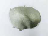
도 1은 전자빔 용해 방식의 3D 프린터를 이용하여 순수 티타늄 분말로부터 제조한 두개골 임플란트의 사진이다.
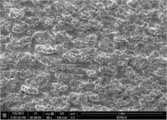
도 2는 전자빔 용해 방식의 3D 프린터를 이용하여 순수 티타늄 분말로부터 제조한 두개골 임플란트의 표면을 주사전자 현미경으로 촬영한 사진이다.
도 3은 3D 프린팅을 이용하여 순수 티타늄 분말로부터 제조한 두개골 임플란트의 표면을 소정의 조건에서 마이크로블라스팅 처리한 후의 사진이다.
도 4는 3D 프린팅을 이용하여 순수 티타늄 분말로부터 제조한 두개골 임플란트의 표면을 소정의 조건에서 마이크로블라스팅 처리한 후 주사전자 현미경으로 촬영한 사진이다.1 is a photograph of a skull implant prepared from pure titanium powder using an electron beam dissolution type 3D printer.
FIG. 2 is a photograph of a surface of a skull implant prepared from pure titanium powder using an electron beam dissolution type 3D printer and scanning the surface with a scanning electron microscope.
FIG. 3 is a photograph of a surface of a skull implant prepared from pure titanium powder using a 3D printing method after microblasting with a predetermined condition. FIG.
FIG. 4 is a photograph of a surface of a skull implant prepared from pure titanium powder by micro-blasting using a scanning electron microscope under predetermined conditions using 3D printing.
이하, 본 발명을 실시예를 통하여 구체적으로 설명한다. 다만, 하기 실시예는 본 발명의 기술적 특징을 명확하게 예시하기 위한 것 일뿐, 본 발명의 보호범위를 한정하는 것은 아니다.Hereinafter, the present invention will be described in detail with reference to examples. However, the following examples are intended to clearly illustrate the technical features of the present invention and do not limit the scope of protection of the present invention.
1.One.분석 방법Analysis method
(1) 금속 임플란트의 표면 조도(1) Surface roughness of metal implants
금속 임플란트의 표면 조도(roughness, Rauhigkeit)는 표면 조도계(모델명 : Dektak 150; 제조사 : Veeco, 미국)를 이용하여 측정하였다.The surface roughness (Rauhigkeit) of the metal implant was measured using a surface roughness meter (Model: Dektak 150; manufactured by Veeco, USA).
(2) 금속 임플란트의 압축 강도(2) Compressive strength of metal implants
금속 임플란트의 압축 강도는 만능재료시험기(모델명 : Instron 5966; 제조사 : Instron Engineering Co., 미국)를 이용하여 측정하였다. 만능재료시험기의 cross head speed를 5 ㎜/min 으로 하여 시편을 압축하였고, 최대 압축 하중을 측정하였다.The compressive strength of the metal implant was measured using an universal material tester (Model: Instron 5966; manufactured by Instron Engineering Co., USA). The specimens were compressed at a cross head speed of 5 mm / min in the universal testing machine and the maximum compressive load was measured.
2. 3D2. 3D프린팅을Printing 이용한 두개골 임플란트의 제조 Manufacture of Cranial Implants Used
2차원 의료용 CT/MRI 이미지를 3차원 설계 디자인으로 역설계하여 3D 프린터용 데이터를 획득하였다. 이후, 상기 3D 프린터용 데이터에 기초하여 2등급의 순수 티타늄(평균 입도 : 73㎛) 분말을 전자빔 용해(Electron Beam Melting, EBM) 방식의 3D 프린터(모델명 : A2X; 제조사 : Arcam AB, 스웨덴)로 적층가공하고 두개골 임플란트를 제조하였다. 제조된 두개골 임플란트의 표면 조도는 약 45㎛ 이었고, 최대 압축 하중은 약 2,800 뉴튼(N) 이었다.2D medical CT / MRI images were reversely designed with 3D design design to obtain data for 3D printer. Then, powder of pure titanium (average particle size: 73 mu m) of
도 1은 전자빔 용해 방식의 3D 프린터를 이용하여 순수 티타늄 분말로부터 제조한 두개골 임플란트의 사진이다. 또한, 도 2는 전자빔 용해 방식의 3D 프린터를 이용하여 순수 티타늄 분말로부터 제조한 두개골 임플란트의 표면을 주사전자 현미경으로 촬영한 사진이다. 도 1 및 도 2에서 보이는 바와 같이 전자빔 용해 방식의 3D 프린터를 이용하여 순수 티타늄 분말로부터 제조한 두개골 임플란트는 표면에 잔류 분말 및 외부 응력에 쉽게 분리될 수 있는 가결합 분말이 존재하였고, 표면이 매우 거칠었다.1 is a photograph of a skull implant prepared from pure titanium powder using an electron beam dissolution type 3D printer. 2 is a photograph of a surface of a cranial implant fabricated from pure titanium powder using an electron beam dissolution type 3D printer and taken with a scanning electron microscope. As shown in FIG. 1 and FIG. 2, a skull implant made from pure titanium powder using an electron beam dissolution type 3D printer has residual powder on the surface and a pre-bonded powder which can be easily separated from external stress. It was rough.
3. 3D3. 3D프린팅을Printing 이용하여 제조한 두개골 임플란트의 Of the cranial implants마이크로블라스팅Microblasting 처리 process
앞에서 제조한 두개골 임플란트의 표면을 마이크로블라스팅(구체적으로 숏 피닝, shot peening) 처리하였다. 마이크로블라스팅 처리시 미디어(Media)로 400㎛ 크기의 강제 미립자 숏을 사용하였고, 미디어 분사 압력은 3 바(bar) 이었고, 미디어 분사량은 두개골 임플란트 표면적 400㎠ 을 기준으로 약 7㎏ 이었고, 미디어 분사 시간은 1분 이었다. 마이크로블라스팅 처리된 두개골 임플란트의 표면 조도는 약 3㎛ 이었고, 최대 압축 하중은 약 5,100 뉴튼(N) 이었다.The surfaces of the previously prepared skull implants were subjected to microblasting (specifically, shot peening). The media injection pressure was 3 bar and the media injection amount was about 7 kg based on the surface area of the cranial implant of 400
도 3은 3D 프린팅을 이용하여 순수 티타늄 분말로부터 제조한 두개골 임플란트의 표면을 소정의 조건에서 마이크로블라스팅 처리한 후의 사진이다. 또한, 도 4는 3D 프린팅을 이용하여 순수 티타늄 분말로부터 제조한 두개골 임플란트의 표면을 소정의 조건에서 마이크로블라스팅 처리한 후 주사전자 현미경으로 촬영한 사진이다. 도 3 및 도 4에서 보이는 바와 같이 3D 프린팅을 이용하여 제조한 두개골 임플란트의 표면을 소정의 조건에서 마이크로블라스팅 처리하였을 때 표면에 존재하는 잔류 분말 및 외부 응력에 쉽게 분리될 수 있는 가결합 분말이 제거되었고, 표면이 매끄러워졌다.FIG. 3 is a photograph of a surface of a skull implant prepared from pure titanium powder using a 3D printing method after microblasting with a predetermined condition. FIG. FIG. 4 is a photograph of a surface of a skull implant prepared from pure titanium powder by micro-blasting using a scanning electron microscope under a predetermined condition, using 3D printing. As shown in FIGS. 3 and 4, when the surface of the cranial implant manufactured using 3D printing was subjected to microblasting at a predetermined condition, the residual powder present on the surface and the covalent powder easily separated from the external stress were removed And the surface was smooth.
이상에서와 같이 본 발명을 상기의 실시예를 통해 설명하였지만 본 발명이 반드시 여기에만 한정되는 것은 아니며 본 발명의 범주와 사상을 벗어나지 않는 범위 내에서 다양한 변형실시가 가능함은 물론이다. 따라서, 본 발명의 보호범위는 본 발명에 첨부된 특허청구의 범위에 속하는 모든 실시 형태를 포함하는 것으로 해석되어야 한다.While the present invention has been particularly shown and described with reference to exemplary embodiments thereof, it is to be understood that the invention is not limited to the disclosed exemplary embodiments, but, on the contrary, is intended to cover various modifications and equivalent arrangements included within the spirit and scope of the appended claims. Therefore, the scope of the present invention should be construed as including all embodiments falling within the scope of the appended claims.
Claims (10)
Translated fromKorean상기 금속 재료는 티타늄 또는 티타늄 합금에서 선택되고,
상기 3D 프린팅 방법은 전자빔 용해(Electron Beam Melting, EBM) 방법이고,
상기 마이크로블라스팅 처리시 미디어(Media)는 250~450㎛ 크기의 강제 미립자이고, 미디어 분사 압력은 3~5 바(bar) 에서 선택되고, 미디어 분사량은 금속 임플란트 표면적 400㎠ 을 기준으로 4~8㎏ 에서 선택되고, 미디어 분사 시간은 30초 내지 10분에서 선택되며,
상기 마이크로블라스팅 처리 후 두개골 금속 임플란트의 표면 조도는 1~8㎛ 인 것을 특징으로 하는 금속 임플란트의 표면특성 개질방법.
1. A method comprising microblasting a surface of a skull metal implant prepared by molding a metal material with a 3D printing method,
Wherein the metallic material is selected from titanium or a titanium alloy,
The 3D printing method is an electron beam melting (EBM) method,
In the microblending process, the media is a forceful particle having a size of 250 to 450 μm, a media injection pressure is selected at 3 to 5 bar, a media injection amount is 4 to 8 kg And the media ejection time is selected from 30 seconds to 10 minutes,
Wherein the surface roughness of the skull metal implant after the microblasting treatment is 1 to 8 占 퐉.
The method of claim 1, wherein the cranial metal implant is a customized implant for orthopedic implant.
Priority Applications (1)
| Application Number | Priority Date | Filing Date | Title |
|---|---|---|---|
| KR1020150113394AKR101603903B1 (en) | 2015-08-11 | 2015-08-11 | Method for modifying surface property of metal implant manufactured by 3D printing |
Applications Claiming Priority (1)
| Application Number | Priority Date | Filing Date | Title |
|---|---|---|---|
| KR1020150113394AKR101603903B1 (en) | 2015-08-11 | 2015-08-11 | Method for modifying surface property of metal implant manufactured by 3D printing |
Publications (1)
| Publication Number | Publication Date |
|---|---|
| KR101603903B1true KR101603903B1 (en) | 2016-03-17 |
Family
ID=55651663
Family Applications (1)
| Application Number | Title | Priority Date | Filing Date |
|---|---|---|---|
| KR1020150113394AActiveKR101603903B1 (en) | 2015-08-11 | 2015-08-11 | Method for modifying surface property of metal implant manufactured by 3D printing |
Country Status (1)
| Country | Link |
|---|---|
| KR (1) | KR101603903B1 (en) |
Cited By (7)
| Publication number | Priority date | Publication date | Assignee | Title |
|---|---|---|---|---|
| KR101758853B1 (en)* | 2017-01-16 | 2017-07-17 | 주식회사 쓰리디프리욜 | Cleaning method of 3 dimensional printed implant |
| KR101921281B1 (en)* | 2017-12-01 | 2018-11-22 | 선문대학교 산학협력단 | Method for manufacturing article using additive manufacturing and surface treatment |
| KR20200003297A (en)* | 2018-06-15 | 2020-01-09 | 부산대학교 산학협력단 | Method and apparatus for treating wearproof metal surface |
| KR20200019279A (en)* | 2018-08-07 | 2020-02-24 | 한국생산기술연구원 | 3d printing method for easy removal of support |
| KR20200045029A (en) | 2018-10-11 | 2020-05-04 | 한국생산기술연구원 | Method for treating surface of metal products |
| KR20200101480A (en)* | 2019-01-28 | 2020-08-28 | 연세대학교 산학협력단 | 3d implant used for cranioplasty and method for manufacturing the same |
| KR20210028617A (en) | 2018-10-11 | 2021-03-12 | 한국생산기술연구원 | Method for treating surface of metal products |
Citations (1)
| Publication number | Priority date | Publication date | Assignee | Title |
|---|---|---|---|---|
| JP2007262568A (en)* | 2005-12-06 | 2007-10-11 | Howmedica Osteonics Corp | Laser manufactured porous surface |
- 2015
- 2015-08-11KRKR1020150113394Apatent/KR101603903B1/enactiveActive
Patent Citations (1)
| Publication number | Priority date | Publication date | Assignee | Title |
|---|---|---|---|---|
| JP2007262568A (en)* | 2005-12-06 | 2007-10-11 | Howmedica Osteonics Corp | Laser manufactured porous surface |
Cited By (13)
| Publication number | Priority date | Publication date | Assignee | Title |
|---|---|---|---|---|
| KR101758853B1 (en)* | 2017-01-16 | 2017-07-17 | 주식회사 쓰리디프리욜 | Cleaning method of 3 dimensional printed implant |
| KR101921281B1 (en)* | 2017-12-01 | 2018-11-22 | 선문대학교 산학협력단 | Method for manufacturing article using additive manufacturing and surface treatment |
| WO2019108043A1 (en)* | 2017-12-01 | 2019-06-06 | 선문대학교 산학협력단 | Method for manufacturing surface-treated additive manufactured article |
| KR20200003297A (en)* | 2018-06-15 | 2020-01-09 | 부산대학교 산학협력단 | Method and apparatus for treating wearproof metal surface |
| KR102100038B1 (en)* | 2018-06-15 | 2020-04-10 | 부산대학교 산학협력단 | Method and apparatus for treating wearproof metal surface |
| KR102135825B1 (en) | 2018-08-07 | 2020-07-20 | 한국생산기술연구원 | 3d printing method for easy removal of support |
| KR20200019279A (en)* | 2018-08-07 | 2020-02-24 | 한국생산기술연구원 | 3d printing method for easy removal of support |
| KR20200045029A (en) | 2018-10-11 | 2020-05-04 | 한국생산기술연구원 | Method for treating surface of metal products |
| KR20210028617A (en) | 2018-10-11 | 2021-03-12 | 한국생산기술연구원 | Method for treating surface of metal products |
| KR102340440B1 (en) | 2018-10-11 | 2021-12-17 | 한국생산기술연구원 | Method for treating surface of metal products |
| KR20200101480A (en)* | 2019-01-28 | 2020-08-28 | 연세대학교 산학협력단 | 3d implant used for cranioplasty and method for manufacturing the same |
| WO2020159173A3 (en)* | 2019-01-28 | 2020-10-22 | 연세대학교 산학협력단 | Three-dimensional implant used in cranioplasty and method for manufacturing same |
| KR102238428B1 (en) | 2019-01-28 | 2021-04-09 | 연세대학교 산학협력단 | 3d implant used for cranioplasty and method for manufacturing the same |
Similar Documents
| Publication | Publication Date | Title |
|---|---|---|
| KR101603903B1 (en) | Method for modifying surface property of metal implant manufactured by 3D printing | |
| Tamayo et al. | Additive manufacturing of Ti6Al4V alloy via electron beam melting for the development of implants for the biomedical industry | |
| Bandyopadhyay et al. | 3D printing for bone regeneration | |
| Velásquez-García et al. | Biomedical applications of metal 3D printing | |
| US11173549B2 (en) | Process for producing a beta-alloy titanium niobium zirconium (TNZ) with a very low modulus of elasticity for biomedical applications and its embodiment by additive manufacturing | |
| Liang et al. | Recent advances in 3D printing of biodegradable metals for orthopaedic applications | |
| US10426869B2 (en) | Biodegradable magnesium alloys and composites | |
| Kanazawa et al. | Fabrication of titanium alloy frameworks for complete dentures by selective laser melting | |
| Liu et al. | Additive manufacturing techniques and their biomedical applications | |
| CN106457394A (en) | DMLS orthopedic intramedullary device and manufacturing method | |
| Alipour et al. | A review on in vitro/in vivo response of additively manufactured Ti–6Al–4V alloy | |
| CN112691233A (en) | 3D printing interbody fusion cage and preparation method thereof | |
| Yaqoob et al. | Novel method for the production of titanium foams to reduce stress shielding in implants | |
| de Freitas et al. | Sintering behaviour of Co-28% Cr-6% Mo compacted blocks for dental prosthesis | |
| Myszka et al. | Comparison of dental prostheses cast and sintered by SLM from Co-Cr-Mo-W alloy | |
| CN101128165A (en) | Preparation method of medical implant made of β-titanium molybdenum alloy and corresponding implant | |
| Gali et al. | 3D Printing: the future technology in prosthodontics | |
| Santos et al. | CoCrMo-base alloys for dental applications obtained by selective laser melting (slm) and cad/cam milling | |
| JP7263745B2 (en) | Zr alloys, Zr alloy products and Zr alloy parts | |
| Elbadawi et al. | Progress in bioactive metal and, ceramic implants for load-bearing application | |
| Sharma et al. | 3D Printable titanium alloys and their properties in biomedical applications: state of the art | |
| Fukuda | Additive manufacturing technology for orthopedic implants | |
| Mergulhão et al. | Perspective of additive manufacturing selective laser melting in Co-Cr-Mo alloy in the consolidation of dental prosthesis | |
| Gehrke et al. | Quasi‐static strength and fractography analysis of two dental implants manufactured by direct metal laser sintering | |
| Bose et al. | Binder jet additive manufacturing of biomaterials |
Legal Events
| Date | Code | Title | Description |
|---|---|---|---|
| PA0109 | Patent application | Patent event code:PA01091R01D Comment text:Patent Application Patent event date:20150811 | |
| PA0201 | Request for examination | ||
| PA0302 | Request for accelerated examination | Patent event date:20150916 Patent event code:PA03022R01D Comment text:Request for Accelerated Examination Patent event date:20150811 Patent event code:PA03021R01I Comment text:Patent Application | |
| PE0902 | Notice of grounds for rejection | Comment text:Notification of reason for refusal Patent event date:20151113 Patent event code:PE09021S01D | |
| AMND | Amendment | ||
| E601 | Decision to refuse application | ||
| PE0601 | Decision on rejection of patent | Patent event date:20160126 Comment text:Decision to Refuse Application Patent event code:PE06012S01D Patent event date:20151113 Comment text:Notification of reason for refusal Patent event code:PE06011S01I | |
| X091 | Application refused [patent] | ||
| AMND | Amendment | ||
| PX0901 | Re-examination | Patent event code:PX09011S01I Patent event date:20160126 Comment text:Decision to Refuse Application Patent event code:PX09012R01I Patent event date:20160111 Comment text:Amendment to Specification, etc. | |
| PX0701 | Decision of registration after re-examination | Patent event date:20160308 Comment text:Decision to Grant Registration Patent event code:PX07013S01D Patent event date:20160219 Comment text:Amendment to Specification, etc. Patent event code:PX07012R01I Patent event date:20160126 Comment text:Decision to Refuse Application Patent event code:PX07011S01I Patent event date:20160111 Comment text:Amendment to Specification, etc. Patent event code:PX07012R01I | |
| X701 | Decision to grant (after re-examination) | ||
| GRNT | Written decision to grant | ||
| PR0701 | Registration of establishment | Comment text:Registration of Establishment Patent event date:20160310 Patent event code:PR07011E01D | |
| PR1002 | Payment of registration fee | Payment date:20160311 End annual number:3 Start annual number:1 | |
| PG1601 | Publication of registration | ||
| FPAY | Annual fee payment | Payment date:20190102 Year of fee payment:4 | |
| PR1001 | Payment of annual fee | Payment date:20190102 Start annual number:4 End annual number:4 | |
| FPAY | Annual fee payment | Payment date:20191223 Year of fee payment:5 | |
| PR1001 | Payment of annual fee | Payment date:20191223 Start annual number:5 End annual number:5 | |
| PR1001 | Payment of annual fee | Payment date:20201228 Start annual number:6 End annual number:6 | |
| PR1001 | Payment of annual fee | Payment date:20220103 Start annual number:7 End annual number:7 | |
| PR1001 | Payment of annual fee | Payment date:20230102 Start annual number:8 End annual number:8 | |
| PR1001 | Payment of annual fee | Payment date:20231220 Start annual number:9 End annual number:9 | |
| PR1001 | Payment of annual fee | Payment date:20241223 Start annual number:10 End annual number:10 |