KR101603748B1 - Control apparatus for checking and changing insulating gas of load break switch on live wire state and method thereof - Google Patents
Control apparatus for checking and changing insulating gas of load break switch on live wire state and method thereofDownload PDFInfo
- Publication number
- KR101603748B1 KR101603748B1KR1020150133001AKR20150133001AKR101603748B1KR 101603748 B1KR101603748 B1KR 101603748B1KR 1020150133001 AKR1020150133001 AKR 1020150133001AKR 20150133001 AKR20150133001 AKR 20150133001AKR 101603748 B1KR101603748 B1KR 101603748B1
- Authority
- KR
- South Korea
- Prior art keywords
- gas
- pressure
- analysis
- recovery
- ground switch
- Prior art date
- Legal status (The legal status is an assumption and is not a legal conclusion. Google has not performed a legal analysis and makes no representation as to the accuracy of the status listed.)
- Ceased
Links
- 238000000034methodMethods0.000titleclaimsabstractdescription70
- 239000007789gasSubstances0.000claimsabstractdescription108
- 238000011084recoveryMethods0.000claimsabstractdescription53
- 238000007689inspectionMethods0.000claimsabstractdescription16
- 239000002912waste gasSubstances0.000claimsabstractdescription9
- 238000009530blood pressure measurementMethods0.000claimsabstractdescription6
- 238000009413insulationMethods0.000claimsdescription8
- 238000005259measurementMethods0.000claimsdescription4
- 238000003915air pollutionMethods0.000claimsdescription2
- 229910018503SF6Inorganic materials0.000description15
- SFZCNBIFKDRMGX-UHFFFAOYSA-Nsulfur hexafluorideChemical compoundFS(F)(F)(F)(F)FSFZCNBIFKDRMGX-UHFFFAOYSA-N0.000description15
- 229960000909sulfur hexafluorideDrugs0.000description15
- 238000002347injectionMethods0.000description5
- 239000007924injectionSubstances0.000description5
- 230000002950deficientEffects0.000description4
- 238000003912environmental pollutionMethods0.000description4
- 238000012986modificationMethods0.000description3
- 230000004048modificationEffects0.000description3
- 230000003014reinforcing effectEffects0.000description3
- QAOWNCQODCNURD-UHFFFAOYSA-NSulfuric acidChemical compoundOS(O)(=O)=OQAOWNCQODCNURD-UHFFFAOYSA-N0.000description2
- 230000005856abnormalityEffects0.000description2
- 230000000694effectsEffects0.000description2
- 238000004880explosionMethods0.000description2
- 238000013021overheatingMethods0.000description2
- 230000002159abnormal effectEffects0.000description1
- 230000032683agingEffects0.000description1
- 230000004075alterationEffects0.000description1
- 238000013459approachMethods0.000description1
- 230000001419dependent effectEffects0.000description1
- 230000014509gene expressionEffects0.000description1
- 238000009434installationMethods0.000description1
- 238000007789sealingMethods0.000description1
- 238000000926separation methodMethods0.000description1
- 238000012163sequencing techniqueMethods0.000description1
- 239000000243solutionSubstances0.000description1
- 239000000126substanceSubstances0.000description1
- 238000012546transferMethods0.000description1
- XLYOFNOQVPJJNP-UHFFFAOYSA-NwaterSubstancesOXLYOFNOQVPJJNP-UHFFFAOYSA-N0.000description1
Images


Classifications
- H—ELECTRICITY
- H01—ELECTRIC ELEMENTS
- H01H—ELECTRIC SWITCHES; RELAYS; SELECTORS; EMERGENCY PROTECTIVE DEVICES
- H01H33/00—High-tension or heavy-current switches with arc-extinguishing or arc-preventing means
- H01H33/02—Details
- H01H33/53—Cases; Reservoirs, tanks, piping or valves, for arc-extinguishing fluid; Accessories therefor, e.g. safety arrangements, pressure relief devices
- H01H33/56—Gas reservoirs
- H01H33/563—Gas reservoirs comprising means for monitoring the density of the insulating gas
- H—ELECTRICITY
- H01—ELECTRIC ELEMENTS
- H01H—ELECTRIC SWITCHES; RELAYS; SELECTORS; EMERGENCY PROTECTIVE DEVICES
- H01H9/00—Details of switching devices, not covered by groups H01H1/00 - H01H7/00
- H01H9/30—Means for extinguishing or preventing arc between current-carrying parts
- H01H2009/305—Means for extinguishing or preventing arc between current-carrying parts including means for screening for arc gases as protection of mechanism against hot arc gases or for keeping arc gases in the arc chamber
Landscapes
- Gas-Insulated Switchgears (AREA)
Abstract
Translated fromKoreanDescription
Translated fromKorean본 발명은 활선 지상 개폐기의 절연가스 점검 교체 컨트롤장치 및 이를 이용한 절연가스 점검 교체공법에 관한 것으로서, 보다 구체적으로는, 지상 개폐기의 절연가스에 대한 회수, 충전, 분석 등 일련의 과정을 자동 프로세스(Process)로 적용하여 목표 순도치에 도달할 수 있도록 하되 수작업에 의존하던 기존의 방식을 자동화하여 수작업에서 발생할 수 있는 과회수, 과충전 등 오차발생률을 최대한 낮추고, 기존의 폐가스를 액화하여 수집함으로써 환경오염을 최소화할 수 있도록 한 것이다.
BACKGROUND OF THE
일반적으로, 변전소에서 전력 수용가 측으로 공급하는 전력은 대략 22,000V에서 26,000V로 승압시켜 공급하고 있는데, 이 경우 전력회사에서는 전력계통의 보호를 위해 인도변의 지상이나 옥외에 전원공급을 제어할 수 있는 지상 개폐기를 설치하여 사용하고 있으며, 이러한 지상 개폐기의 내부에는 절연가스가 충진되어 있다.Generally, the power supplied from the substation to the power supply side is increased from approximately 22,000V to 26,000V. In this case, the electric power company has a ground The ground switch is filled with insulating gas inside.
지상 개폐기의 내부에 충진되는 절연가스로는 절연특성이 우수한 육불화황(SF6) 가스가 주로 사용되며, 육불화황(SF6) 가스는 물리적, 화학적, 전기적 성질이 매우 우수하고, 절연 내력과 소호 능력이 뛰어나 고전압과 대전력 차단에 적합한 것으로 알려져 있다.Sulfur hexafluoride (SF6) gas, which has excellent insulation properties, is mainly used as an insulating gas to be filled in the ground switch. SF6 gas has excellent physical, chemical and electrical properties, Are known to be suitable for high voltage and high power cutoff.
이러한 지상 개폐기는 고압 전류가 흐르는 지상 개폐기에 행인이 접근하는 경우 인명사고, 특히 폭우 또는 폭설 등에 기인한 습기에 의해 내부가 노화되거나, 외부로 방전되어 감전사고 등과 같은 인명사고가 발생하는 것을 방지하기 위하여 지상 개폐기의 경우에는 개폐기를 탱크로 완전 밀봉하여 절연에 만전을 기하고 있다.Such a ground switch may prevent accidents such as accidents such as electric shock due to aging of the inside due to humidity caused by human accidents, especially rain caused by heavy rain or heavy snow when a passenger approaches the ground switch with high voltage current, In the case of ground switchgear, the switchgear is completely sealed with a tank to ensure insulation.
그러나 밀봉 특성이 우수한 지상 개폐기의 경우에도 외부 기온의 급격한 상승, 과부화, 지락, 단락 등에 기인한 이상 전류에 의해 지상 개폐기의 탱크 내의 압력이 급격히 상승되면 지상 개폐기의 탱크 내부에 충진된 절연가스가 순간 6 ~ 10㎏/㎠ 이상의 고압력으로 팽창되어 개폐기의 탱크가 폭발되는 사고가 발생하고 있다.However, even in the case of a ground switch having excellent sealing characteristics, if the pressure in the tank of the ground switch is suddenly increased due to an abnormal current caused by a sudden increase in external temperature, overload, ground fault or short circuit, It is inflated at a high pressure of 6 to 10 kg / cm < 2 > or more to cause an explosion of the tank of the switch.
이에 따라, 지상 개폐기의 폭발 사고 등을 방지하기 위하여 노후화가 진행된 지상 개폐기들을 우선적으로 선정하여 점검한 후, 이상 유무에 따라 해당 지상 개폐기를 교체해야 하지만, 지상 개폐기 전부를 교체하는 경우 비교적 고가의 지상 개폐기 교체에 따른 막대한 비용과, 긴 작업시간으로 현실적으로 어려운 실정이었다.Accordingly, in order to prevent an explosion accident of the ground switch, it is necessary to first select and check the aged ground switch, and then replace the ground switch when there is an abnormality. However, if the ground switch is replaced, It was difficult in reality because of the huge cost of replacing the switch and the long working time.
이러한 문제를 해결하기 위하여 대한민국 등록특허 10-1178897호(등록일 : 2012. [0007] 08. 27)에는 지상 개폐기와 같은 지상기기에 충진된 절연가스가 손상에 의해 누설되거나 외부 환경에 의해 열화되는 경우, 지상기기 자체를 교체하지 않고도 용이하게 지상기기를 절연보강하여 누설을 막고, 절연가스의 교체를 신속하고 자동적으로 수행할 수 있는 지상기기의 절연가스 분석 및 보강방법에 대해 제안된 바 있었다.In order to solve such a problem, Korean Patent No. 10-1178897 (Registered: 2012. [0007] 08. 27) discloses that when an insulating gas filled in a ground device such as a ground switch is leaked due to damage or deteriorated by an external environment There has been proposed a method for inspecting and reinforcing insulated gas of a ground apparatus capable of easily inserting and reinforcing a ground apparatus without replacing the ground apparatus itself to prevent leakage and quickly and automatically replacing the insulated gas.
상기 대한민국 등록특허 10-1178897호에서 제안된 지상기기의 절연가스 분석 및 보강방법에서는 절연가스를 포함하고 있는 지상기기의 주입구에 일률적으로 정형화된 커넥터를 부착하여 지상기기의 주입구를 통해 절연가스를 배출하고, 배출된 절연가스를 이용하여 절연가스의 순도, 아황산 수분함량 등을 측정하여 이상 유무를 점검하였다.In the method of analyzing and reinforcing the insulating gas of the ground apparatus proposed in Korean Patent No. 10-1178897, a uniformly shaped connector is attached to the inlet of the ground apparatus including the insulating gas, and the insulating gas is discharged through the inlet of the ground apparatus And the purity of the insulating gas and the water content of the sulfuric acid were measured using the discharged insulating gas, and the abnormality was checked.
그러나 상기 대한민국 등록특허 10-1178897호에서와 같이 일률적으로 정형화된 커넥터를 부착하여 절연가스를 배출하거나 충진 시 커넥터의 진공통로가 협소하여 진공작업이 장시간 소요되는 등의 문제가 발생하였다.However, as described in Korean Patent No. 10-1178897, there is a problem that a uniformly shaped connector is attached to discharge the insulating gas or the vacuum passage of the connector is narrowed during the filling, and the vacuum operation takes a long time.
특히, 지상기기, 즉 지상 개폐기의 주입구는 각 지상 개폐기의 제조사별로 구조가 다르기 때문에 일률적으로 정형화된 커넥터를 부착하여 진공작업을 수행하는 경우 작업이 번거로울 뿐만 아니라 작업시간이 장시간 소요되어 수용가의 불편을 초래하는 등의 문제가 발생하였다.Particularly, since the structure of the grounding device, that is, the opening of the ground switch, differs according to the maker of each ground switch, it is troublesome to perform a vacuum operation by attaching a uniformly shaped connector, and the operation time is long, And the like.
이러한 문제를 해결하기 위하여 본 출원인에 의해 2013년 5월 7일자로 출원되어 2013년 9월 12자로 등록된 대한민국 등록특허 10-1310280호에는 "지상 개폐기의 절연가스 점검 및 교체방법"이 제안된 바 있으나, 대한민국 등록특허 10-1310280호는 사선 상태에서 지상 개폐기의 절연가스 점검 및 교체방법에 관한 것으로서, 사선 상태에서 지상 개폐기의 절연가스 점검 및 교체방법은 정전 상태에서 작업이 수행됨에 따라 안전성은 담보할 수 있으나, 수용가에게 불편함을 초래하고, 지상 변압기의 엘보 분리 등으로 인해 교체 비용이 과다 발생하는 등의 문제가 발생하였다.In order to solve such a problem, Korean Patent No. 10-1310280, filed on May 7, 2013 and registered as 12 in September, 2013, has proposed a method for inspecting and replacing insulated gas of a ground switch However, Korean Patent No. 10-1310280 discloses a method for inspecting and replacing insulated gas of a ground switch in an oblique line state. In the method of inspecting and replacing insulated gas of a ground switch in an oblique line, However, it causes inconvenience to the customer, and the replacement cost is excessively generated due to the elbow separation of the ground transformer.
특히 종래기술의 경우에는 교체작업을 수행하는 과정에서 작업자의 숙련도 등에 따라 과회수 및 과충전의 우려가 있다고 지적되고 있는 바 정형화된 일련의 회수, 충전, 분석의 프로세스(Process)를 사전에 입력된 최저압과 최고압을 설정하여 자동적으로 수행하여 안정적이고 일관된 작업의 필요성이 대두된다.
Particularly, in the case of the prior art, it is pointed out that there is a fear of over-recovery and over-charging according to skill of the operator in the process of performing the replacement work, and it is pointed out that the process of recovering, The pressure and the maximum pressure are automatically set by setting the pressure and the need for stable and consistent operation.
본 발명의 목적은, 지상 개폐기의 절연가스에 대한 회수, 충전, 분석 등 일련의 과정을 자동 프로세스(Process)로 적용하여 목표 순도치에 도달할 수 있도록 하되 수작업에 의존하던 기존의 방식을 자동화하여 수작업에서 발생할 수 있는 과회수, 과충전 등 오차발생률을 최대한 낮추고, 기존의 폐가스를 액화하여 수집함으로써 환경오염을 최소화할 수 있도록 한, 활선 지상 개폐기의 절연가스 점검 교체 컨트롤장치 및 이를 이용한 절연가스 점검 교체공법을 제공하는 것이다.
SUMMARY OF THE INVENTION An object of the present invention is to automate an existing method which is dependent on a manual operation so that a target sequence can be reached by applying a series of processes such as recovery, charging and analysis of an insulating gas of a ground switch to an automatic process Insulation gas inspection and replacement control device for live ground switchgear, which minimizes the environmental pollution by collecting and collecting the existing waste gas by minimizing the error incidence such as overflow and overcharge which can occur in manual operation, To provide a method.
상기 목적은, 가스의 회수, 충전, 분석을 컨트롤하는 컨트롤 박스(Control Box); 가스의 성분을 분석하는 분석기(Analyser); 및 가스를 회수하는 회수기(Recovery machine)가 하나의 모듈형태로 이루어지며; 상기 컨트롤 박스에서 최저 가스압과 정격압력을 설정해주면, 상기 최저 가스압 도달시 회수 단계에서 충전 단계로 자동 전환되고, 상기 정격압력 도달시 충전 단계에서 분석 단계로 자동 전환되도록 구성된 것을 특징으로 하는 활선 지상 개폐기의 절연가스 점검 교체 컨트롤 장치에 의해 달성된다.The object is achieved by a control box for controlling the collection, filling and analysis of gas; An analyzer for analyzing the components of the gas; And a recovery machine for recovering the gas are formed in a single module form; Wherein when the minimum gas pressure and the rated pressure are set in the control box, the automatic switch is made to the filling step in the recovery step when the minimum gas pressure has been reached, and automatically switched to the analysis step in the filling step when the rated pressure is reached. Of insulated gas inspection replacement control device.
상기 컨트롤 박스의 측면부에는 절연가스의 인렛 홀(SF6 Gas In Let Hole), 회수를 위한 아웃렛 홀(Out Let Hole), 분석을 위한 아웃렛 홀(Out Let Hole)이 형성될 수 있다.An inlet hole (SF6 Gas In Let Hole) for the insulating gas, an outlet hole (Out Let Hole) for recovery, and an outlet hole (Out Let Hole) for analysis may be formed on the side portion of the control box.
상기 컨트롤 박스는, 자동화 공정 중 예기치 못한 상황 발생 시에 장치를 중지시킬 수 있는 비상정지스위치(Emergency Stop Switch); 지상 개폐기 중 정격압력이 5psi의 경우 선택할 수 있는 버튼; 상기 지상 개폐기 중 정격압력이 7psi의 경우 선택할 수 있는 버튼; 상기 지상 개폐기 중 정격압력이 10psi의 경우 선택할 수 있는 버튼; 회수, 충전, 분석단계에서 현상황을 보여주는 램프들; 상기 회수, 충전, 분석단계에서 현상황을 보여주는 램프들에 대응되는 다수의 버튼들; 상기 지상 개폐기에 전원이 인가되어 작업이 가능함을 알려 주는 램프; 및 교체 전 순도측정이 끝난 후 자동화 공정을 시작하는 버튼을 포함할 수 있다.The control box may include an emergency stop switch capable of stopping the device when an unexpected situation occurs during an automation process; Selectable button for ground pressure switch with rated
한편, 상기 목적은, 디지털 게이지를 사용하여 절연가스의 압력을 측정하는 압력측정 단계; 교체전 분석기로 점검 분석을 하여 절연가스 교체 여부를 판단하는 점검 분석 단계; 지상 개폐기의 안정성 확보를 위해 안전구역(Green Zone)내에서 폐가스를 회수하는 회수 단계; 새로운 가스를 충전하는 충전 단계; 회수와 충전 상태를 분석하는 분석 단계;를 포함하며, 상기한 단계를 반복하여 목표치에 도달하면 분석 완료 후, 최종 압력을 측정하는 최종 압력측정 단계를 더 포함하며, 상기 압력측정 단계, 상기 점검 분석 단계, 상기 회수 단계, 상기 충전 단계, 상기 분석 단계 및 상기 최종 압력측정 단계는 자동 프로세스(Process)로 진행되는 것을 특징으로 하는 활선 상태에서 컨트롤장치를 이용한 절연가스 점검 교체공법에 의해 달성된다.The above object can be achieved by a pressure measuring method comprising: measuring a pressure of an insulating gas using a digital gauge; A check analysis step for checking whether or not the insulated gas is replaced by performing a check analysis with the pre-replacement analyzer; A recovery step of recovering waste gas in a green zone to secure stability of the ground switch; A charging step for charging a new gas; Further comprising a final pressure measuring step of measuring final pressure after completion of the analysis when the step is repeated to reach a target value, wherein the pressure measuring step, the checking analysis Wherein the charging step, the charging step, the analyzing step, and the final pressure measuring step are performed in an automatic process.
상기 회수 단계의 수행 시 최저 2psi 정도를 남겨두고 회수작업을 진행할 수 있다.The recovery operation can be performed while leaving at least about 2 psi in the recovery step.
컨트롤 박스의 설정모드부에 최저 가스압과 정격 압력을 설정해주어 최저 가스압 도달시 상기 회수 단계에서 상기 충전 단계로 자동 진행되도록 하여 과회수의 위험을 방지할 수 있도록 하고, 정격 압력 도달시 상기 충전 단계에서 상기 분석 단계로 자동 진행되도록 할 수 있다.The minimum gas pressure and the rated pressure are set in the set mode portion of the control box so that the minimum gas pressure reaches the minimum gas pressure so as to automatically proceed to the charging step in the recovery step to prevent the risk of over- So that it can be automatically progressed to the analysis step.
상기 최종 압력측정 단계의 수행 후, 목표 순도에 도달하면 컨트롤 장치에 내장되어 있는 작업 종료 알람이 울리되 이후에는 절연가스 주입구의 누기여부를 리크 디텍터(Leak Detector)를 이용 체크한 후에 절연가스 주입구를 마개로 밀봉할 수 있다.After the completion of the final pressure measurement step, when the target purity is reached, a work completion alarm built in the control device is turned on. After that, whether or not the insulating gas inlet is leaking is checked by using a leak detector, It can be sealed with a stopper.
본 발명에 따르면, 지상 개폐기의 절연가스에 대한 회수, 충전, 분석 등 일련의 과정을 자동 프로세스(Process)로 적용하여 목표 순도치에 도달할 수 있도록 하되 수작업에 의존하던 기존의 방식을 자동화하여 수작업에서 발생할 수 있는 과회수, 과충전 등 오차발생률을 최대한 낮추고, 기존의 폐가스를 액화하여 수집함으로써 환경오염을 최소화할 수 있는 효과가 있다.According to the present invention, a series of processes such as recovery, filling, and analysis of an insulating gas of a ground switch can be applied as an automatic process so as to reach a target net stiffness, It is possible to minimize the occurrence of errors such as overheating and overcharging that may occur in the exhaust gas, and collecting the existing waste gas by liquefaction, thereby minimizing environmental pollution.
특히, 본 발명에 따르면, 기존 수동식 절연가스 교체 방법에 비해 최소압력과 최대압력을 자동으로 제어하여 목표 순도치에 이를 때까지 회수, 충전, 분석을 시행할 수 있게 되므로 활선상태에서도 지상 개폐기에 부하를 주지 않고 안전하게 순도불량 가스를 고순도 가스로 교체할 수 있으며, 교체과정에서 회수되는 불량 가스는 액화하여 탱크에 보관하였다가 SF6 가스정제기로 정제를 하여 고순도로 재사용을 함으로써 환경오염 방지와 경제적 이익을 창출할 수 있는 효과를 제공할 수 있다.
Particularly, according to the present invention, the minimum pressure and the maximum pressure are automatically controlled as compared with the conventional manual insulated gas replacement method, so that it is possible to perform recovery, charging and analysis until the target net degree reaches the target net degree. , The defective gas recovered in the replacement process is liquefied and stored in the tank. It is refined with SF6 gas purifier and reused in high purity to prevent environmental pollution and economic benefit. It is possible to provide an effect that can be created.
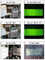
도 1 내지 도 5는 현재 설치 운용중인 지상 개폐기의 회수, 충전, 분석의 회차별 사진.
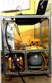
도 6은 지상 개폐기의 구성을 설명하기 위한 사진이다.
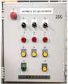
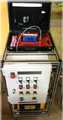
도 7 내지 도 11은 각각 본 발명의 일 실시예에 따른 활선 지상 개폐기의 절연가스 점검 교체 공법을 구현하기 위한 컨트롤 장치의 사진들이다.
도 12는 본 발명의 일 실시예에 따른 활선 지상 개폐기의 절연가스 점검 교체공법의 플로차트이다.
도 13은 본 발명의 일 실시예에 따른 활선 지상 개폐기의 절연가스 점검 교체 공법을 구현하기 위한 컨트롤 장치 최종 완성 사진.Figs. 1 to 5 are photographs showing the recovery, filling, and analysis of the ground-operated switches currently in operation.
6 is a photograph for explaining the configuration of the ground switch.
FIGS. 7 to 11 are photographs of a control device for implementing an insulated gas inspection and replacement method for a live wire ground switch according to an embodiment of the present invention, respectively.
FIG. 12 is a flowchart of an insulated gas inspection and replacement method for a live ground-based switch according to an embodiment of the present invention.
FIG. 13 is a finalized photograph of a control device for implementing insulated gas inspection and replacement of a live ground switch according to an embodiment of the present invention. FIG.
아래에서는 첨부한 도면을 참고로 하여 본 발명의 실시예에 대하여 본 발명이 속하는 기술분야에서 통상의 지식을 가진 자가 용이하게 실시할 수 있도록 상세히 설명한다.Hereinafter, embodiments of the present invention will be described in detail with reference to the accompanying drawings so that those skilled in the art can easily carry out the present invention.
그러나 본 발명에 관한 설명은 구조적 내지 기능적 설명을 위한 실시예에 불과하므로 본 발명의 권리범위는 본문에 설명된 실시예에 의하여 제한되는 것으로 해석되어서는 아니 된다.However, the description of the present invention is merely an example for structural or functional explanation, and thus the scope of the present invention should not be construed as being limited by the embodiments described in the text.
예컨대, 실시예들은 다양한 변경이 가능하고 여러 가지 형태를 가질 수 있기 때문에 본 발명의 권리범위는 기술적 사상을 실현할 수 있는 균등물들을 포함하는 것으로 이해되어야 한다.For example, since the embodiments are susceptible to various modifications and various forms, the scope of the present invention should be construed as including equivalents capable of realizing technical ideas.
또한 본 발명에서 제시된 목적 또는 효과는 특정 실시예가 이를 전부 포함하여야 한다거나 그러한 효과만을 포함하여야 한다는 의미는 아니기 때문에 본 발명의 권리범위는 이에 의하여 제한되는 것으로 이해되어서는 아니 될 것이다.It is to be understood that the scope of the present invention should not be construed as being limited thereto since the object or effect of the present invention is not limited to the specific embodiment.
본 명세서에서, 본 실시예는 본 발명의 개시가 완전하도록 하며, 본 발명이 속하는 기술분야에서 통상의 지식을 가진 자에게 발명의 범주를 완전하게 알려주기 위해 제공되는 것이다. 그리고 본 발명은 청구항의 범주에 의해 정의될 뿐이다.In the present specification, the present embodiment is provided to complete the disclosure of the present invention and to fully disclose the scope of the invention to a person having ordinary skill in the art to which the present invention belongs. And the present invention is only defined by the scope of the claims.
따라서 몇몇 실시예에서, 잘 알려진 구성 요소, 잘 알려진 동작 및 잘 알려진 기술들은 본 발명이 모호하게 해석되는 것을 피하기 위하여 구체적으로 설명되지 않는다.Thus, in some embodiments, well known components, well known operations, and well-known techniques are not specifically described to avoid an undesirable interpretation of the present invention.
한편, 본 발명에서 서술되는 용어의 의미는 사전적 의미에 제한되지 않으며, 다음과 같이 이해되어야 할 것이다.It is to be understood that the meaning of the terms used in the present invention is not limited to a dictionary meaning, but should be understood as follows.
어떤 구성요소가 다른 구성요소에 "연결되어" 있다고 언급된 때에는, 그 다른 구성요소에 직접적으로 연결될 수도 있지만, 중간에 다른 구성요소가 존재할 수도 있다고 이해되어야 할 것이다. 반면에, 어떤 구성요소가 다른 구성요소에 "직접 연결되어" 있다고 언급된 때에는 중간에 다른 구성요소가 존재하지 않는 것으로 이해되어야 할 것이다. 한편, 구성요소들 간의 관계를 설명하는 다른 표현들, 즉 "~사이에"와 "바로 ~사이에" 또는 "~에 이웃하는"과 "~에 직접 이웃하는" 등도 마찬가지로 해석되어야 한다.It is to be understood that when an element is referred to as being "connected" to another element, it may be directly connected to the other element, but there may be other elements in between. On the other hand, when an element is referred to as being "directly connected" to another element, it should be understood that there are no other elements in between. On the other hand, other expressions that describe the relationship between components, such as "between" and "between" or "neighboring to" and "directly adjacent to" should be interpreted as well.
단수의 표현은 문맥상 명백하게 다르게 뜻하지 않는 한 복수의 표현을 포함하는 것으로 이해되어야 하고, "포함하다" 또는 "가지다" 등의 용어는 설시된 특징, 숫자, 단계, 동작, 구성요소, 부분품 또는 이들을 조합한 것이 존재함을 지정하려는 것이며, 하나 또는 그 이상의 다른 특징이나 숫자, 단계, 동작, 구성요소, 부분품 또는 이들을 조합한 것들의 존재 또는 부가 가능성을 미리 배제하지 않는 것으로 이해되어야 한다.It should be understood that the singular " include "or" have "are to be construed as including a stated feature, number, step, operation, component, It is to be understood that the combination is intended to specify that it does not preclude the presence or addition of one or more other features, integers, steps, operations, elements, components, or combinations thereof.
여기서 사용되는 모든 용어들은 다르게 정의되지 않는 한, 본 발명이 속하는 분야에서 통상의 지식을 가진 자에 의해 일반적으로 이해되는 것과 동일한 의미를 가진다.All terms used herein have the same meaning as commonly understood by one of ordinary skill in the art to which this invention belongs, unless otherwise defined.
일반적으로 사용되는 사전에 정의되어 있는 용어들은 관련 기술의 문맥상 가지는 의미와 일치하는 것으로 해석되어야 하며, 본 발명에서 명백하게 정의하지 않는 한 이상적이거나 과도하게 형식적인 의미를 지니는 것으로 해석될 수 없다.Commonly used predefined terms should be interpreted to be consistent with the meanings in the context of the related art and can not be interpreted as having ideal or overly formal meaning unless explicitly defined in the present invention.
이하, 도면을 참조하여 본 발명의 실시예를 상세히 설명한다. 실시예의 설명 중 동일한 구성에 대해서는 동일한 참조부호를 부여하도록 하며, 경우에 따라 동일한 참조부호에 대한 설명은 생략하도록 한다.Hereinafter, embodiments of the present invention will be described in detail with reference to the drawings. In the description of the embodiments, the same components are denoted by the same reference numerals, and explanations of the same reference numerals will be omitted in some cases.
도 1 내지 도 5는 현재 설치 운용중인 지상 개폐기의 회수, 충전, 분석의 회차별 사진으로서, 회수, 충전, 분석이 이루어지면서 점차 가스의 순도가 향상되는 것을 알 수 있다.FIGS. 1 to 5 are photographs showing the recovery, filling, and analysis of the ground switch during the installation and operation, respectively. As the recovery, charging, and analysis are performed, the purity of the gas gradually improves.
도 6은 지상 개폐기의 구성을 설명하기 위한 사진이다.6 is a photograph for explaining the configuration of the ground switch.
이 도면을 참조하면, 본 실시예에 적용되는 지상 개폐기(100)는 개폐기 외함(111)과, 내부에 차단기(도시되지 않음)가 내장되고 절연가스가 충진되는 개폐기 내함(112)과, 개폐기 내함(112)에 마련되고 절연가스가 주입되는 절연가스 주입구(113)와, 개폐기 내함(112)의 내부에 충진된 절연가스의 압력을 표시하는 절연가스 압력계(114)와, 각 수용가나 지상 변압기로 제공되는 케이블이 연결되는 차단기의 선로 연결용 부싱(115)과, 접지 케이블용 부싱(116)을 포함한다.Referring to this figure, the
이외에도, 지상 개폐기(100)에는 제어박스, 절연가스의 온도-압력 특성 표시계, PT와 연결하는 부싱, 차단기의 정격사항을 표시하는 명판, 회로별 접지 시 사용하는 접지단자 등이 더 설치될 수 있는데, 이들에 대해서는 편의상 생략했다.In addition, the
도 7 내지 도 11은 각각 본 발명의 일 실시예에 따른 활선 지상 개폐기의 절연가스 점검 교체공법을 구현하기 위한 컨트롤 장치의 사진들이고, 도 12는 본 발명의 일 실시예에 따른 활선 지상 개폐기의 절연가스 점검 교체공법의 플로차트이며, 도 13은 본 발명의 일 실시예에 따른 활선 지상 개폐기의 절연가스 점검 교체 공법을 구현하기 위한 컨트롤 장치 최종 완성 사진.
FIGS. 7 to 11 are photographs of a control device for implementing an insulated gas inspection and replacement method for a live ground-based breaker according to an embodiment of the present invention, FIG. 12 is a view showing an insulation of a live ground breaker according to an embodiment of the present invention, FIG. 13 is a finalized photograph of a control device for implementing an insulated gas inspection and replacement method for a live ground-based switch according to an embodiment of the present invention. FIG.
한편, 본 발명은 한국전력공사의 지상 개폐기(100)의 절연가스(SF6 GAS)에 대한 자동화기기를 이용하여 불량 가스를 자동으로 교체 하여 순도(99%), SO2(0 PPM) 수분 (500 PPM이하)의 성질을 유지하기 위한 자동화 교체 공법으로 과회수 및 과충전을 사전에 방지하며, 회수 가스를 액화하여 회수하므로 대기방출을 최소화할 수 있는 친환경적인 공법으로 주입 회수 호스의 탈/부착이 없이 안정적으로 교체작업을 수행할 수 있는 공법이다.In the meantime, the present invention automatically removes defective gas by using automation equipment for insulated gas (SF6 GAS) of the
전술한 것처럼 지상 개폐기는 각 제조회사별로 절연가스(SF6 GAS) 주입구 형태와 크기가 다양하며 개폐기 탱크의 용량도 다르므로 개폐기별 가스 교체작업을 상황에 맞게 진행해야 하는 기존의 수동방식으로는 작업자의 숙련도 및 방식의 차이에 기인하는 과회수 및 과충전이 발생할 수 있으므로 이를 방지하기 위한 자동화된 기기의 도입이 절실한 상황인데, 본 발명은 이를 해결하기 위한 방안을 제시한다.As described above, since the type and size of the insulated gas (SF6 gas) inlet are different according to each manufacturer and the capacity of the switch tank is different, the conventional manual method in which the gas replacement work for each switch must be performed according to the situation, It is necessary to introduce an automated device to prevent the over-recovery and the overcharge due to the difference in proficiency and the method, and the present invention proposes a solution for this.
우선, 도 12를 먼저 참조하여 지상 개폐기(100)의 구조에서 개폐기 내함(112)에 충진되는 절연가스를 용이하게 점검 및 교체하기 위한 방법에 대해 설명한다.First, referring to FIG. 12, a method for easily inspecting and replacing insulated gas filled in the switchgear under
본 발명에 따른 활선 지상 개폐기의 절연가스 점검 교체 공법은, 압력측정 단계(S10), 점검 분석단계(S11), 회수 단계(S12), 충전 단계(S13), 분석 단계(S14), 최종 압력측정 단계(S15)를 포함할 수 있다.The insulated gas inspection and replacement method of the live ground switch according to the present invention is characterized in that the insulated gas inspection and replacement method of the present invention comprises a pressure measuring step (S10), a checking analysis step (S11), a collecting step (S12), a filling step (S13) Step S15 may be included.
압력측정 단계(S10)는 절연가스의 압력을 측정하는 단계로서, 압력측정 시 지상 개폐기(100)에 내장된 아날로그 게이지를 통해 육안으로 측정할 수도 있으나 간혹 게이지 불량으로 정확한 내압을 보여주지 못하는 사례가 있는 바 본 발명에서는 정밀한 디지털 게이지를 병행하여 측정하고 있다.The pressure measuring step (S10) is a step of measuring the pressure of the insulating gas. Although it can be measured with the naked eye through the analogue gauge embedded in the
점검 분석 단계(S11)은 절연가스의 교체 전 분석기로 점검 분석을 하여 절연가스의 교체 여부를 판단하는 단계이다.The inspection and analysis step (S11) is a step of checking whether the insulation gas is replaced or not by checking analysis with the pre-replacement analyzer of the insulated gas.
회수 단계(S12)는 지상 개폐기(100)의 안정성 확보를 위해 안전구역(Green Zone)내에서 폐가스를 회수하는 단계로서, 최저 2psi정도는 남겨두어서 회수작업을 시행할 수 있다.The recovery step S12 is a step of recovering the waste gas in the green zone in order to secure the stability of the
충전 단계(S13)는 새로운 가스를 충전하는 단계이다. 가스의 회수 및 충전 과정 시 기존의 수동 교체 방법은 아날로그 게이지를 측정하는 방법이 작업자 별로 조금씩 차이가 나게 되는 바, 활선상태에서의 과회수는 지상 개폐기(100)에 부담을 줄 수도 있는 위험성을 내포하게 된다.The charging step S13 is a step of charging a new gas. In the conventional manual replacement method, the method of measuring the analogue gauge is slightly different for each worker during recovery and charging of the gas, and the recovery in the live state may impose a burden on the
이를 위해 본 발명에서는 컨트롤 박스의 설정모드부에 최저 가스압을 설정해둠으로써 자동으로 회수과정에서 다음 충전단계로 진행되도록 하여 과회수의 위험을 방지할 수 있도록 하고 있다.To this end, in the present invention, by setting the lowest gas pressure in the setting mode part of the control box, it is possible to automatically proceed to the next charging step in the recovery process, thereby preventing the risk of over-recovery.
또한 충전 단계 역시 사전에 설정한 압력제어부의 값에 도달하면 자동으로 분석 단계로 진행되도록 하였다.Also, the charging step is automatically proceeded to the analyzing step when the preset pressure control value is reached.
이는 작업도중 발생할 수 있는 과회수 및 과압의 위험을 자동화 프로세스(Process)를 통하여 일괄 제어, 사전에 차단 할 수 있으므로 지상 개폐기(100)의 안정성 확보에 크게 기여한다 하겠다.This can greatly reduce the risk of over-recovery and over-pressure that may occur during the operation because it can block and control in advance through an automatic process, thereby securing stability of the
분석 단계(S14)는 회수와 충전 상태를 분석한다.The analysis step (S14) analyzes the recovery and charge state.
최종 압력측정 단계(S15)는 컨트롤 박스의 전면부에는 지상 개폐기(100)의 표준압력인 압력입력부가 설치되어 있는데 5psi, 7psi, 10psi, 그리고 수동메뉴로 설정할 수 있도록 되어 있다.In the final pressure measurement step (S15), the pressure input portion, which is the standard pressure of the
예컨대, 5psi로 설정한 후 시작버튼을 누르면 2psi까지 회수 후 자동으로 5psi까지 충전을 진행한 다음, 분석을 자동으로 진행하게 된다. 이때, 목표 순도에 도달하여 컨트롤 박스에 내장되어 있는 작업 종료 알람이 울리면 작업자는 최종적으로 디지털 압력계를 이용하여 지상 개폐기(100)의 내부에 부착된 표찰의 적정 압력여부를 확인한 후 절연가스 주입구(113)의 누기여부를 리크 디텍터(Leak Detector)를 이용 체크한 후 절연가스 주입구(113)를 마개로 밀봉하면 작업이 종료된다.For example, if you press the start button after setting it to 5 psi, it will collect up to 2 psi and then automatically charge to 5 psi, and then the analysis will proceed automatically. At this time, when the target purity is reached and a work end alarm built in the control box is turned on, the operator finally confirms whether or not the mark attached to the inside of the
이때, 앞서도 기술한 것처럼 본 발명에 따른 컨트롤 박스의 측면부에는 절연가스의 인렛 홀(SF6 Gas In Let Hole), 회수를 위한 아웃렛 홀(Out Let Hole), 분석을 위한 아웃렛 홀(Out Let Hole)이 형성되어 있어서 기존의 쓰리웨이밸브(Three Way valve) 방식의 복잡한 호스 구성 대신 컨트롤 박스와 직렬로 된 단일의 호스만을 사용하면 되기 때문에 좀 더 간결한 작업환경을 구성할 수 있고 제어 또한 간편하게 이루어 질 수 있다.At this time, as described above, the control box according to the present invention has an inlet hole SF6 gas inlet hole, an outlet let hole for recovery, and an outlet let hole for analysis. It is possible to use only a single hose in series with the control box instead of the conventional three way valve type hose configuration so that a more compact working environment can be constructed and control can be made easily .
또한 수동식 교체방법에서 발생할 수밖에 없는 공정 간의 인터벌 타임을 최소화할 수 있어 효율성 제고도 기대할 수 있다. In addition, it is possible to minimize the interval time between processes that can occur in the manual replacement method, thereby improving the efficiency.
또한 작업과정 중 예기치 못한 상황 발생 시 비상정지스위치(Emergency Stop Switch)를 장착하여 자동화 공정이 진행 중에도 프로세스(Process)를 정지시킬 수 있도록 하여 전체적인 안전성을 도모할 수 있다.In addition, when an unexpected situation occurs during the work process, the Emergency Stop Switch can be installed so that the process can be stopped even during the automation process, thereby achieving overall safety.
한편, 이와 같은 방법을 수행하기 위한 컨트롤 장치는 도 7 내지 도 11에 도시된 바와 같이, 가스의 회수, 충전, 분석을 컨트롤하는 컨트롤 박스(Control Box, 200), 분석기(Analyser) 및 회수기(Recovery machine)가 모듈형태로 이루어져 있는 것을 특징으로 한다. 따라서 회수와 충전 분석과정을 정밀 센서를 이용해 컨트롤할 수 있게 되어 컨트롤의 신뢰성이 높아질 수 있다.As shown in FIGS. 7 to 11, a control device for performing such a method includes a
이때, 컨트롤 장치의 측면부에는 절연가스의 인렛 홀(SF6 Gas In Let Hole), 회수를 위한 아웃렛 홀(Out Let Hole), 분석을 위한 아웃렛 홀(Out Let Hole)이 형성되어 있으며, 작업과정 중 예기치 못한 상황 발생 시 프로세스(Process)를 정지시킬 수 있도록 하는 비상정지스위치(Emergency Stop Switch, 도 7 참조)가 탑재되어 있다.At this time, the control unit has an inlet hole (SF6 Gas In Let Hole) for the insulating gas, an outlet hole (Out Let Hole) for the recovery and an outlet hole (Out Let Hole) for the analysis. An emergency stop switch (see FIG. 7) for stopping the process when an unexpected situation occurs is mounted.
또한 폐가스 회수과정에서는 지상 개폐기(100) 내부의 순도미달 가스는 액화과정을 거쳐 회수탱크로 안전하게 수집되도록 하여 대기오염도 최소화할 수 있도록 한다.Also, in the waste gas recovery process, the purity gas inside the
컨트롤 장치에 대해 도 7 내지 도 11, 도 13을 참조하여 알아본다.The control device will be described with reference to Figs. 7 to 11 and Fig.
도 7을 참조하면, 컨트롤 박스(200)의 전면 왼편 상단에는 비상정지스위치(Emergency Stop Switch)가 위치해 있으며, 상단 중앙에는 개폐기별 적정압력 제어부가 있고, 중앙에는 단계별 상황을 보여주는 램프부가 있으며, 그 바로 밑에는 단계별 작업공정을 보여주는 제어부가 위치하고 있다. 그리고 컨트롤 박스(200)의 하단부 좌측에는 파워 램프가, 우측에는 오토 스타트 스위치(Auto Start Switch)가 위치해 있다.7, an Emergency Stop Switch is located at the upper left of the front side of the
좀 더 구체적으로 알아보면 도 7의 1번은 자동화 공정 중 예기치 못한 상황 발생 시에 작업을 중지시킬 수 있는 비상정지스위치(Emergency Stop Switch)로서, 자동화 공정을 취소하고 매뉴얼 컨트롤이 가능토록 하는 푸쉬 버튼이다.More specifically, FIG. 7 shows an emergency stop switch (Emergency Stop Switch) capable of stopping the operation when an unexpected situation occurs during the automation process. It is a push button for canceling the automatic process and enabling manual control .
도 7의 2번은 지상 개폐기(100) 중 정격압력이 5psi의 경우 선택할 수 있는 버튼이다. 지상 개폐기(100) 내부에 기록되어 있는 표시찰을 통하여 작업자가 선택할 수 있다.7 is a button that can be selected when the rated pressure of the
도 7의 3번은 지상 개폐기(100) 중 정격압력이 7psi의 경우 선택할 수 있는 버튼이다.7 is a button that can be selected when the rated pressure of the
도 7의 4번은 지상 개폐기(100) 중 정격압력이 10psi의 경우 선택할 수 있는 버튼이다.Numeral 4 in FIG. 7 is a button that can be selected when the ground pressure of the
도 7의 5,6,7번은 각 공정별 진행상황을 보여주는 램프로 회수, 충전, 분석단계에서 현상황을 보여주는 램프이다.7, 5, 6 and 7 are lamps showing the progress of each process, and lamps showing the current situation in the recovery, charging and analysis stages.
도 7의 8번은 장치의 프로세스가 현재 회수 단계임을 알려주는 버튼으로 해당 버튼의 바로 위쪽 램프가 점등되며, 지상 개폐기(100) 내부의 불량 가스를 회수용 탱크로 내보내는 상태이며, 사전에 설정해 놓은 최저압에 도달 시까지 회수기(Recovery Machine)를 통해 기체상태의 불량 가스는 액화과정을 거쳐 회수 탱크로 보내진다.7 is a button for notifying that the process of the apparatus is the current collecting step, a lamp immediately above the corresponding button is turned on, and the defective gas in the
도 7의 9번은 충전 과정임을 알려주는 버튼으로 해당 단계일 때 위쪽의 램프가 점등된다. 사전에 설정한 적정압이 되면 다음 단계인 분석과정으로 자동으로 넘어가게 된다. 충전단계에서 10kg/㎠ 미만의 적정압으로 주입될 수 있도록 압력조정기(Regulator)를 거쳐 지상 개폐기(100)의 To Switch 커플러를 통해 개폐기의 주입구로 충전되는 과정이다.A
도 7의 10번은 지상 개폐기(100)가 분석과정임을 보여주는 것으로 분석버튼 위의 램프가 점등되며 적정압까지 충전되면 자동으로 분석단계로 넘어가게 된다.7 shows that the
지상 개폐기(100) 내부에 충전된 가스는 지상 개폐기(100)의 측면에 위치한 분석기(Analyzer) 커플러를 통해 모듈형태로 장착된 SF6 Gas 분석기(SF6 Multigas Analyzer)를 통하여 SF6, SO2, H2O의 값을 3분간 측정한 후 목표 순도치에 도달하면 컨트롤 장치 내부에 장착된 종료 알람이 작동된다.The gas filled in the
도 7의 11번은 지상 개폐기(100)에 전원이 인가되어 작업이 가능함을 알려 주는 램프이다.7 is a lamp for informing that the
그리고 도 7의 12번은 교체 전 순도측정이 끝난 후 자동화 공정을 시작하는 버튼으로 12번 버튼을 누르면 회수, 충전, 분석의 전공정이 목표 순도치에 이를 때까지 반복적으로 과정을 되풀이 할 수 있다.In FIG. 7, 12 is a button for starting the automated process after the pre-replacement purity measurement is completed. When the
한편, 도 8의 L1 은 To Switch Coupler로 컨트롤 장치와 지상 개폐기(100) 간의 연결구로 기밀이 보장되는 커플러에 의해 연결되며 모든 단계별 가스 이동통로 역할을 하게 된다. 이때, 각 지상 개폐기별 주입구의 형태와 모양이 다른데 당사에서는 대한민국 등록특허10-1310280(등록일2013년 09월 12일: 당사 보유 특허)를 통해 기 해결하였고 이를 바탕으로 모든 종류의 개폐기와 연결이 가능, 교체가 가능함을 보여준다.In FIG. 8, L1 is a To Switch Coupler, which is connected to the connection between the control device and the
또한 기존의 쓰리웨이밸브(Three Way Valve)방식과 비교하면 주입구에 걸리는 하중을 줄여주어 주입구 파손의 우려도 경감시킬 수 있다.Compared with the conventional three-way valve method, the load applied to the injection port is reduced, thereby reducing the risk of damage to the injection port.
도 8 L2는 컨트롤 장치에 전원을 인가해주는 파워 서플라이(Power Supply)이다Figure 8 L2 is a power supply that powers the control device
도 9의 R1은 절연가스의 인렛 커플러(SF6 Gas In Let Coupler)로 컨트롤 장치로 고순도 절연가스가 연결구로 이 또한 기밀이 보장되는 커플러에 의해 연결되며 가스 탱크와 컨트롤 장치 사이에는 압력 조정기(Regulator)를 통하여 가스가 일정한 압력으로 유입될 수 있도록 한다.In Fig. 9, R1 is an insulated gas inlet coupler (SF6 Gas Inject Coupler), which is connected to the controller by a coupler ensuring high purity insulation gas to the connection port, and a pressure regulator is connected between the gas tank and the control device. So that the gas can be introduced at a constant pressure.
도 9의 R2는 충전후 분석기로 가는 메인 라인이다.R2 in FIG. 9 is the main line to the post-charge analyzer.
도 9의 R3은 분석기(Analasyer) 연결용 커플로(Coupler)로서 교체 작업 전 순도측정 및 목표 순도치에 이르기까지 각 공정별 순도를 측정하게 되며 SF6 Multigas Analasyer를 이용하여 SF6, SO2, H2O의 값을 측정하는 과정이다.9 is a Coupler for analyzer connection. The purity of each process is measured up to the purity measurement before the replacement operation and the target purity. The SF6, SO2, and H2O values are measured using a SF6 Multigas Analyzer .
도 9의 R4는 회수기(Recovery Machine)로 연결된 가스 회수 호스이다.In Fig. 9, R4 is a gas recovery hose connected to a recovery machine.
도 10의 1은 상단에 장착된 분석기이고, 2는 컨트롤 박스(200)의 전면부 사진이다.In Fig. 10,
도 11의 1은 분석기 2는 컨트롤 박스(200), 3은 회수기, 4는 회수용 탱크의 사진이다.11, the
이상 설명한 바와 같은 구조와 작용을 갖는 본 실시예에 따르면, 지상 개폐기의 절연가스에 대한 회수, 충전, 분석 등 일련의 과정을 자동 프로세스(Process)로 적용하여 목표 순도치에 도달할 수 있도록 하되 수작업에 의존하던 기존의 방식을 자동화하여 수작업에서 발생할 수 있는 과회수, 과충전 등 오차발생률을 최대한 낮추고, 기존의 폐가스를 액화하여 수집함으로써 환경오염을 최소화할 수 있게 된다.According to the present embodiment having the structure and function as described above, it is possible to apply a series of processes such as recovery, charging and analysis of the insulating gas of the ground switch to an automatic process so as to reach the target net degree of order, It is possible to minimize the occurrence of errors such as overheating and overcharging which may occur in manual operation by minimizing the environmental pollution by collecting and collecting the existing waste gas.
이와 같이 본 발명은 기재된 실시예에 한정되는 것이 아니고, 본 발명의 사상 및 범위를 벗어나지 않고 다양하게 수정 및 변형할 수 있음은 이 기술의 분야에서 통상의 지식을 가진 자에게 자명하다. 따라서 그러한 수정예 또는 변형예들은 본 발명의 청구범위에 속한다 하여야 할 것이다.
It will be apparent to those skilled in the art that various modifications and variations can be made in the present invention without departing from the spirit or scope of the invention. It is therefore intended that such modifications or alterations be within the scope of the claims appended hereto.
100 : 지상 개폐기 111 : 개폐기 외함
112 : 개폐기 내함 113 : 절연가스 주입구
114 : 절연가스 압력계 115 : 선로 연결용 부싱
116 : 접지 케이블용 부싱 200 : 컨트롤 박스100: ground switch 111: switchgear enclosure
112: Actuator deck 113: Insulating gas inlet
114: insulated gas pressure gauge 115: bushing for line connection
116: bushing for grounding cable 200: control box
Claims (7)
Translated fromKorean가스의 성분을 분석하는 분석기(Analyser); 및
가스를 회수하는 회수기(Recovery machine)가 하나의 모듈형태로 이루어지며;
상기 컨트롤 박스에서 최저 가스압과 정격압력을 설정해주면, 상기 최저 가스압 도달시 회수 단계에서 충전 단계로 자동 전환되고, 상기 정격압력 도달시 충전 단계에서 분석 단계로 자동 전환되도록 구성된 것을 특징으로 하는 활선 지상 개폐기의 절연가스 점검 교체 컨트롤 장치.
Emergency Stop Switch which can stop the device when unexpected situation occurs during the automation process, button to be selected when the rated pressure is 5 psi among the ground switch, A button that can be selected when the rated pressure of the ground switch is 10 psi, lamps showing the current state in the recovery, charging and analysis stages, and a plurality of buttons corresponding to the lamps showing the current state in the recovery, A control box for controlling the recovery, charging and analysis of the gas, comprising a lamp indicating that the ground switch is powered by the power source and a button for starting an automation process after the pre-replacement purity measurement is completed, ;
An analyzer for analyzing the components of the gas; And
A recovery machine for recovering the gas is formed in a module form;
Wherein when the minimum gas pressure and the rated pressure are set in the control box, the automatic switch is made to the filling step in the recovery step when the minimum gas pressure has been reached, and automatically switched to the analysis step in the filling step when the rated pressure is reached. Insulated gas check replacement control device.
상기 컨트롤 박스의 측면부에는 절연가스의 인렛 홀(SF6 Gas In Let Hole), 회수를 위한 아웃렛 홀(Out Let Hole), 분석을 위한 아웃렛 홀(Out Let Hole)이 형성되어 있는 것을 특징으로 하는 활선 지상 개폐기의 절연가스 점검 교체 컨트롤 장치.
The method according to claim 1,
(SF6 Gas In Let Hole), an outlet hole (Out Let Hole) for collection, and an outlet hole (Out Let Hole) for analysis are formed on the side of the control box. Insulation gas inspection and replacement control device of switchgear.
교체 전 분석기로 점검 분석을 하여 절연가스 교체 여부를 판단하는 점검 분석 단계;
지상 개폐기의 안정성 확보를 위해 안전구역(Green Zone) 내에서 대기오염을 최소화할 수 있도록 순도미달 가스를 액화 과정을 거쳐 회수탱크로 수집하되, 최저 2psi 정도를 남겨두고 폐가스를 회수하는 회수 단계;
새로운 가스를 충전하는 충전 단계;
회수와 충전 상태를 분석하는 분석 단계;를 포함하며,
상기한 단계를 반복하여 목표치에 도달하면 분석 완료 후, 최종 압력을 측정하는 최종 압력측정 단계를 더 포함하며,
컨트롤 박스의 설정모드부에 최저 가스압과 정격 압력을 설정해주어 최저 가스압 도달시 상기 회수 단계에서 상기 충전 단계로 자동 진행되도록 하여 과회수의 위험을 방지할 수 있도록 하고, 정격 압력 도달시 상기 충전 단계에서 상기 분석 단계로 자동 진행되고,
상기 압력측정 단계, 상기 점검 분석 단계, 상기 회수 단계, 상기 충전 단계, 상기 분석 단계 및 상기 최종 압력측정 단계는 자동 프로세스(Process)로 진행되는 것을 특징으로 하는 활선 지상 개폐기의 절연가스 점검 교체 공법.A pressure measuring step of measuring the pressure of the insulating gas using a digital gauge;
A check analysis step for checking whether or not the insulated gas is replaced by performing a check analysis with the pre-replacement analyzer;
Collecting the undersurface gas into a recovery tank through a liquefaction process so as to minimize air pollution within the green zone to ensure stability of the ground switch, recovering the waste gas while leaving a minimum of 2 psi;
A charging step for charging a new gas;
And an analysis step of analyzing the number of times of collection and the state of charge,
Further comprising a final pressure measuring step of measuring a final pressure after the completion of the analysis when the above step is repeated to reach the target value,
The minimum gas pressure and the rated pressure are set in the set mode portion of the control box so that the minimum gas pressure reaches the minimum gas pressure so as to automatically proceed to the charging step in the recovery step to prevent the risk of over- Automatically proceeds to the analysis step,
Wherein the pressure measurement step, the inspection analysis step, the recovery step, the filling step, the analysis step, and the final pressure measurement step are performed in an automatic process.
Priority Applications (1)
| Application Number | Priority Date | Filing Date | Title |
|---|---|---|---|
| KR1020150133001AKR101603748B1 (en) | 2015-09-21 | 2015-09-21 | Control apparatus for checking and changing insulating gas of load break switch on live wire state and method thereof |
Applications Claiming Priority (1)
| Application Number | Priority Date | Filing Date | Title |
|---|---|---|---|
| KR1020150133001AKR101603748B1 (en) | 2015-09-21 | 2015-09-21 | Control apparatus for checking and changing insulating gas of load break switch on live wire state and method thereof |
Publications (1)
| Publication Number | Publication Date |
|---|---|
| KR101603748B1true KR101603748B1 (en) | 2016-03-15 |
Family
ID=55542365
Family Applications (1)
| Application Number | Title | Priority Date | Filing Date |
|---|---|---|---|
| KR1020150133001ACeasedKR101603748B1 (en) | 2015-09-21 | 2015-09-21 | Control apparatus for checking and changing insulating gas of load break switch on live wire state and method thereof |
Country Status (1)
| Country | Link |
|---|---|
| KR (1) | KR101603748B1 (en) |
Cited By (1)
| Publication number | Priority date | Publication date | Assignee | Title |
|---|---|---|---|---|
| KR101705498B1 (en) | 2016-10-27 | 2017-02-10 | 주식회사 건영종합전기 | Gas changing method using insulation gas withdrawing-charging apparatus |
Citations (7)
| Publication number | Priority date | Publication date | Assignee | Title |
|---|---|---|---|---|
| KR20060041580A (en) | 2004-11-09 | 2006-05-12 | 브이케이 주식회사 | Head-up Display System for Mobile Communication Terminal Screen of Vehicle |
| KR20100122540A (en) | 2009-05-13 | 2010-11-23 | 브이앤아이 주식회사 | Apparatus for displaying information in hud system of automotive vehicles |
| KR20110112102A (en) | 2010-04-06 | 2011-10-12 | 엘지전자 주식회사 | Information display |
| KR20130036934A (en) | 2011-10-05 | 2013-04-15 | 팅크웨어(주) | Mobile terminal for performing head up display function, operating method thereof, and routine informing device interacting thereof |
| KR101310280B1 (en) | 2013-05-07 | 2013-09-24 | 대흥전력기술 주식회사 | Method for checking and changing insulating gas of load break switch |
| KR101315995B1 (en)* | 2013-05-06 | 2013-10-10 | 샤론일렉콤 주식회사 | Apparatus for managing insulating gas of ground equipment in live wire and method thereof |
| KR101371667B1 (en)* | 2013-12-27 | 2014-03-07 | 대흥전력기술 주식회사 | Method for checking and changing insulating gas of load break switch on live wire state |
- 2015
- 2015-09-21KRKR1020150133001Apatent/KR101603748B1/ennot_activeCeased
Patent Citations (7)
| Publication number | Priority date | Publication date | Assignee | Title |
|---|---|---|---|---|
| KR20060041580A (en) | 2004-11-09 | 2006-05-12 | 브이케이 주식회사 | Head-up Display System for Mobile Communication Terminal Screen of Vehicle |
| KR20100122540A (en) | 2009-05-13 | 2010-11-23 | 브이앤아이 주식회사 | Apparatus for displaying information in hud system of automotive vehicles |
| KR20110112102A (en) | 2010-04-06 | 2011-10-12 | 엘지전자 주식회사 | Information display |
| KR20130036934A (en) | 2011-10-05 | 2013-04-15 | 팅크웨어(주) | Mobile terminal for performing head up display function, operating method thereof, and routine informing device interacting thereof |
| KR101315995B1 (en)* | 2013-05-06 | 2013-10-10 | 샤론일렉콤 주식회사 | Apparatus for managing insulating gas of ground equipment in live wire and method thereof |
| KR101310280B1 (en) | 2013-05-07 | 2013-09-24 | 대흥전력기술 주식회사 | Method for checking and changing insulating gas of load break switch |
| KR101371667B1 (en)* | 2013-12-27 | 2014-03-07 | 대흥전력기술 주식회사 | Method for checking and changing insulating gas of load break switch on live wire state |
Cited By (1)
| Publication number | Priority date | Publication date | Assignee | Title |
|---|---|---|---|---|
| KR101705498B1 (en) | 2016-10-27 | 2017-02-10 | 주식회사 건영종합전기 | Gas changing method using insulation gas withdrawing-charging apparatus |
Similar Documents
| Publication | Publication Date | Title |
|---|---|---|
| CN102621444B (en) | System and method for detecting high voltage resistance and connection and disconnection performance of socket synchronous to production line | |
| KR102139279B1 (en) | Apparatus and method for automatically shutting off the recovery error of insulated gas | |
| US20140339892A1 (en) | Disconnection unit for disconnecting a battery from a power system and a motor vehicle having a lithium-ion battery | |
| CN105405693A (en) | GIS breaker contact opening and closing condition monitoring system | |
| CN103209853A (en) | Power supply device, method for disconnecting a battery from a connection device and motor vehicle | |
| KR101603748B1 (en) | Control apparatus for checking and changing insulating gas of load break switch on live wire state and method thereof | |
| CN108459230B (en) | Fault detection method for electrical high-voltage equipment | |
| CN114137427A (en) | Method for automatically checking capacity of single storage battery in storage battery pack | |
| KR20150046858A (en) | Checking and repair system of sf6 gas machine | |
| CN207095963U (en) | Gas-insulated switch station rupture pressure disc off-line testing device | |
| CN211853529U (en) | Full-automatic density relay calibration device | |
| KR102697210B1 (en) | Apparatus and method for inspecting inner conductor for dead or live status of gas insulated switchgear | |
| CN103489676B (en) | The method of 220kV GIS device disconnecting link ground cutter deciliter reliability can be improved | |
| CN207067306U (en) | For searching the servicing unit of DC system grounding point failure | |
| CN204613737U (en) | Switch Simulator | |
| CN205680617U (en) | A kind of valve control SF with error locking proof function6density monitor three-way connection | |
| KR101371667B1 (en) | Method for checking and changing insulating gas of load break switch on live wire state | |
| KR20100005384U (en) | Portable Transformer for one phase Equipped with Solid Dielectric Switchgear | |
| CN205388644U (en) | Detection device of spring -operated mechanism | |
| CN212275896U (en) | Simulation circuit breaker test device | |
| KR101043371B1 (en) | Water removal method of current transformer switchgear section using excitation characteristics of current transformer | |
| CN210294433U (en) | Quick cutting device for temperature rise test of transformer | |
| KR101463745B1 (en) | Method for checking and changing insulating gas of load break switch on live wire state | |
| KR101229185B1 (en) | Compressor motor starting box tester for train | |
| CN208384059U (en) | A kind of low pressure withstand-voltage test bench |
Legal Events
| Date | Code | Title | Description |
|---|---|---|---|
| PA0109 | Patent application | Patent event code:PA01091R01D Comment text:Patent Application Patent event date:20150921 | |
| PA0201 | Request for examination | ||
| PA0302 | Request for accelerated examination | Patent event date:20151105 Patent event code:PA03022R01D Comment text:Request for Accelerated Examination Patent event date:20150921 Patent event code:PA03021R01I Comment text:Patent Application | |
| PE0902 | Notice of grounds for rejection | Comment text:Notification of reason for refusal Patent event date:20151208 Patent event code:PE09021S01D | |
| E701 | Decision to grant or registration of patent right | ||
| PE0701 | Decision of registration | Patent event code:PE07011S01D Comment text:Decision to Grant Registration Patent event date:20160307 | |
| GRNT | Written decision to grant | ||
| PR0701 | Registration of establishment | Comment text:Registration of Establishment Patent event date:20160309 Patent event code:PR07011E01D | |
| PR1002 | Payment of registration fee | Payment date:20160310 End annual number:3 Start annual number:1 | |
| PG1601 | Publication of registration | ||
| J204 | Request for invalidation trial [patent] | ||
| PJ0204 | Invalidation trial for patent | Patent event date:20170906 Comment text:Request for Trial Patent event code:PJ02042R01D Patent event date:20160309 Comment text:Registration of Establishment Patent event code:PJ02041E01I Appeal kind category:Invalidation Request date:20170906 Decision date:20180627 Appeal identifier:2017100002857 | |
| J301 | Trial decision | Free format text:TRIAL NUMBER: 2017100002857; TRIAL DECISION FOR INVALIDATION REQUESTED 20170906 Effective date:20180627 | |
| PJ1301 | Trial decision | Patent event code:PJ13011S05D Patent event date:20180627 Comment text:Trial Decision on Invalidation (Patent, Utility Model, Industrial Design) Appeal kind category:Invalidation Request date:20170906 Decision date:20180627 Appeal identifier:2017100002857 | |
| PJ2001 | Appeal | Patent event date:20180627 Comment text:Trial Decision on Invalidation (Patent, Utility Model, Industrial Design) Patent event code:PJ20011S05I Appeal kind category:Invalidation Decision date:20181122 Appeal identifier:2018200006054 Request date:20180726 | |
| PJ1302 | Judgment (patent court) | Patent event date:20181130 Comment text:Written Judgment (Patent Court) Patent event code:PJ13021S01D Request date:20180726 Decision date:20181122 Appeal identifier:2018200006054 Appeal kind category:Invalidation | |
| PJ2002 | Appeal before the supreme court | Comment text:Trial Decision on Invalidation (Patent, Utility Model, Industrial Design) Patent event date:20180627 Patent event code:PJ20021S05I Request date:20181210 Appeal identifier:2018300012196 Appeal kind category:Invalidation Decision date:20190314 | |
| FPAY | Annual fee payment | Payment date:20190225 Year of fee payment:4 | |
| PR1001 | Payment of annual fee | Payment date:20190225 Start annual number:4 End annual number:4 | |
| J221 | Remand (intellectual property tribunal) | Free format text:TRIAL NUMBER: 2019130000060; REMAND (INTELLECTUAL PROPERTY TRIBUNAL) FOR INVALIDATION | |
| J303 | Written judgement (supreme court) | Free format text:TRIAL NUMBER: 2018300012196; JUDGMENT (SUPREME COURT) FOR INVALIDATION REQUESTED 20181210 Effective date:20190314 | |
| PJ1303 | Judgment (supreme court) | Comment text:Written Judgment (Supreme Court) Patent event date:20190401 Patent event code:PJ13031S01D Decision date:20190314 Appeal kind category:Invalidation Request date:20181210 Appeal identifier:2018300012196 | |
| PJ2201 | Remand (intellectual property tribunal) | Request date:20190401 Appeal kind category:Invalidation Appeal identifier:2019130000060 Decision date:20190429 | |
| J301 | Trial decision | Free format text:TRIAL NUMBER: 2019130000060; TRIAL DECISION FOR INVALIDATION REQUESTED 20190401 Effective date:20190429 | |
| PJ1301 | Trial decision | Patent event code:PJ13011S09D Patent event date:20190429 Comment text:Trial Decision on Final Judgment on Revocation Appeal kind category:Invalidation Request date:20190401 Decision date:20190429 Appeal identifier:2019130000060 | |
| PC2102 | Extinguishment | Termination category:Others Termination date:20190701 |