KR101601190B1 - Dispenser and refill unit - Google Patents
Dispenser and refill unitDownload PDFInfo
- Publication number
- KR101601190B1 KR101601190B1KR1020117012401AKR20117012401AKR101601190B1KR 101601190 B1KR101601190 B1KR 101601190B1KR 1020117012401 AKR1020117012401 AKR 1020117012401AKR 20117012401 AKR20117012401 AKR 20117012401AKR 101601190 B1KR101601190 B1KR 101601190B1
- Authority
- KR
- South Korea
- Prior art keywords
- valve element
- annular wall
- cap
- refill unit
- valve
- Prior art date
- Legal status (The legal status is an assumption and is not a legal conclusion. Google has not performed a legal analysis and makes no representation as to the accuracy of the status listed.)
- Expired - Fee Related
Links
Images


Classifications
- B—PERFORMING OPERATIONS; TRANSPORTING
- B67—OPENING, CLOSING OR CLEANING BOTTLES, JARS OR SIMILAR CONTAINERS; LIQUID HANDLING
- B67D—DISPENSING, DELIVERING OR TRANSFERRING LIQUIDS, NOT OTHERWISE PROVIDED FOR
- B67D3/00—Apparatus or devices for controlling flow of liquids under gravity from storage containers for dispensing purposes
- A—HUMAN NECESSITIES
- A47—FURNITURE; DOMESTIC ARTICLES OR APPLIANCES; COFFEE MILLS; SPICE MILLS; SUCTION CLEANERS IN GENERAL
- A47K—SANITARY EQUIPMENT NOT OTHERWISE PROVIDED FOR; TOILET ACCESSORIES
- A47K5/00—Holders or dispensers for soap, toothpaste, or the like
- A47K5/06—Dispensers for soap
- A47K5/12—Dispensers for soap for liquid or pasty soap
- A47K5/1217—Electrical control means for the dispensing mechanism
- A—HUMAN NECESSITIES
- A47—FURNITURE; DOMESTIC ARTICLES OR APPLIANCES; COFFEE MILLS; SPICE MILLS; SUCTION CLEANERS IN GENERAL
- A47K—SANITARY EQUIPMENT NOT OTHERWISE PROVIDED FOR; TOILET ACCESSORIES
- A47K5/00—Holders or dispensers for soap, toothpaste, or the like
- A47K5/06—Dispensers for soap
- A47K5/12—Dispensers for soap for liquid or pasty soap
- A47K5/1202—Dispensers for soap for liquid or pasty soap dispensing dosed volume
- B—PERFORMING OPERATIONS; TRANSPORTING
- B65—CONVEYING; PACKING; STORING; HANDLING THIN OR FILAMENTARY MATERIAL
- B65D—CONTAINERS FOR STORAGE OR TRANSPORT OF ARTICLES OR MATERIALS, e.g. BAGS, BARRELS, BOTTLES, BOXES, CANS, CARTONS, CRATES, DRUMS, JARS, TANKS, HOPPERS, FORWARDING CONTAINERS; ACCESSORIES, CLOSURES, OR FITTINGS THEREFOR; PACKAGING ELEMENTS; PACKAGES
- B65D47/00—Closures with filling and discharging, or with discharging, devices
- B65D47/04—Closures with discharging devices other than pumps
- B65D47/20—Closures with discharging devices other than pumps comprising hand-operated members for controlling discharge
- B65D47/2018—Closures with discharging devices other than pumps comprising hand-operated members for controlling discharge comprising a valve or like element which is opened or closed by deformation of the container or closure
- B65D47/2031—Closures with discharging devices other than pumps comprising hand-operated members for controlling discharge comprising a valve or like element which is opened or closed by deformation of the container or closure the element being formed by a slit, narrow opening or constrictable spout, the size of the outlet passage being able to be varied by increasing or decreasing the pressure
- B—PERFORMING OPERATIONS; TRANSPORTING
- B65—CONVEYING; PACKING; STORING; HANDLING THIN OR FILAMENTARY MATERIAL
- B65D—CONTAINERS FOR STORAGE OR TRANSPORT OF ARTICLES OR MATERIALS, e.g. BAGS, BARRELS, BOTTLES, BOXES, CANS, CARTONS, CRATES, DRUMS, JARS, TANKS, HOPPERS, FORWARDING CONTAINERS; ACCESSORIES, CLOSURES, OR FITTINGS THEREFOR; PACKAGING ELEMENTS; PACKAGES
- B65D47/00—Closures with filling and discharging, or with discharging, devices
- B65D47/04—Closures with discharging devices other than pumps
- B65D47/20—Closures with discharging devices other than pumps comprising hand-operated members for controlling discharge
- B65D47/24—Closures with discharging devices other than pumps comprising hand-operated members for controlling discharge with poppet valves or lift valves, i.e. valves opening or closing a passageway by a relative motion substantially perpendicular to the plane of the seat
- B65D47/248—Closures with discharging devices other than pumps comprising hand-operated members for controlling discharge with poppet valves or lift valves, i.e. valves opening or closing a passageway by a relative motion substantially perpendicular to the plane of the seat the valve being opened or closed by imparting a motion to the valve stem
- B—PERFORMING OPERATIONS; TRANSPORTING
- B65—CONVEYING; PACKING; STORING; HANDLING THIN OR FILAMENTARY MATERIAL
- B65D—CONTAINERS FOR STORAGE OR TRANSPORT OF ARTICLES OR MATERIALS, e.g. BAGS, BARRELS, BOTTLES, BOXES, CANS, CARTONS, CRATES, DRUMS, JARS, TANKS, HOPPERS, FORWARDING CONTAINERS; ACCESSORIES, CLOSURES, OR FITTINGS THEREFOR; PACKAGING ELEMENTS; PACKAGES
- B65D47/00—Closures with filling and discharging, or with discharging, devices
- B65D47/36—Closures with frangible parts adapted to be pierced, torn or removed, to provide discharge openings
- B—PERFORMING OPERATIONS; TRANSPORTING
- B65—CONVEYING; PACKING; STORING; HANDLING THIN OR FILAMENTARY MATERIAL
- B65D—CONTAINERS FOR STORAGE OR TRANSPORT OF ARTICLES OR MATERIALS, e.g. BAGS, BARRELS, BOTTLES, BOXES, CANS, CARTONS, CRATES, DRUMS, JARS, TANKS, HOPPERS, FORWARDING CONTAINERS; ACCESSORIES, CLOSURES, OR FITTINGS THEREFOR; PACKAGING ELEMENTS; PACKAGES
- B65D55/00—Accessories for container closures not otherwise provided for
- B65D55/02—Locking devices; Means for discouraging or indicating unauthorised opening or removal of closure
- B65D55/024—Closures in which a part has to be ruptured to gain access to the contents
- F—MECHANICAL ENGINEERING; LIGHTING; HEATING; WEAPONS; BLASTING
- F16—ENGINEERING ELEMENTS AND UNITS; GENERAL MEASURES FOR PRODUCING AND MAINTAINING EFFECTIVE FUNCTIONING OF MACHINES OR INSTALLATIONS; THERMAL INSULATION IN GENERAL
- F16L—PIPES; JOINTS OR FITTINGS FOR PIPES; SUPPORTS FOR PIPES, CABLES OR PROTECTIVE TUBING; MEANS FOR THERMAL INSULATION IN GENERAL
- F16L37/00—Couplings of the quick-acting type
- F16L37/28—Couplings of the quick-acting type with fluid cut-off means
- F16L37/38—Couplings of the quick-acting type with fluid cut-off means with fluid cut-off means in only one of two pipe-end fittings
- F16L37/40—Couplings of the quick-acting type with fluid cut-off means with fluid cut-off means in only one of two pipe-end fittings with a lift valve being opened automatically when the coupling is applied
- F16L37/413—Couplings of the quick-acting type with fluid cut-off means with fluid cut-off means in only one of two pipe-end fittings with a lift valve being opened automatically when the coupling is applied the lift valve being of the sleeve type, i.e. a sleeve being telescoped over an inner cylindrical wall
- B—PERFORMING OPERATIONS; TRANSPORTING
- B65—CONVEYING; PACKING; STORING; HANDLING THIN OR FILAMENTARY MATERIAL
- B65D—CONTAINERS FOR STORAGE OR TRANSPORT OF ARTICLES OR MATERIALS, e.g. BAGS, BARRELS, BOTTLES, BOXES, CANS, CARTONS, CRATES, DRUMS, JARS, TANKS, HOPPERS, FORWARDING CONTAINERS; ACCESSORIES, CLOSURES, OR FITTINGS THEREFOR; PACKAGING ELEMENTS; PACKAGES
- B65D2401/00—Tamper-indicating means
- B65D2401/15—Tearable part of the closure
Landscapes
- Engineering & Computer Science (AREA)
- Mechanical Engineering (AREA)
- Health & Medical Sciences (AREA)
- Public Health (AREA)
- General Engineering & Computer Science (AREA)
- Closures For Containers (AREA)
- Devices For Dispensing Beverages (AREA)
- Containers And Packaging Bodies Having A Special Means To Remove Contents (AREA)
Abstract
Translated fromKoreanDescription
Translated fromKorean본 발명은 액체 비누 등을 분배하는 디스펜서에 관한 것이다.
The present invention relates to a dispenser for dispensing liquid soap and the like.
디스펜서는 베이스 유닛을 구비하고, 분배될 물질을 함유한 리필 유닛은 뒤집힌 형태로, 즉 최하단부에 배출구를 구비한 형태로 베이스 유닛에 끼워진다. 본 발명은 가정 환경에서 사용하기에 적합하도록 독립적으로 서있는 비누 디스펜서용으로 특수하게 설계되었다. 그러나, 본 발명은 벽걸이 유닛에 적용될 수도 있고, 공중화장실과 같은 대규모의 시설에 사용될 수 있다. 이 장치는 액체를 분배하기 위해 수동으로 작동되는 펌프를 구비할 수도 있지만, 바람직하게는 사용자의 손의 존재를 감지하는 근접 센서를 구비하고, 액체를 자동으로 분배하는 펌프를 구비한다.
The dispenser has a base unit, and the refill unit containing the substance to be dispensed is inserted into the base unit in an inverted form, that is, with the outlet at the lowermost end. The present invention is specifically designed for stand-alone soap dispensers suitable for use in a home environment. However, the present invention may be applied to a wall-mounted unit and may be used in a large-scale facility such as a public toilet. The device may have a manually operated pump to dispense the liquid, but preferably has a proximity sensor that senses the presence of a user's hand and has a pump that dispenses liquid automatically.
디스펜서는 주로 국내 시장용이기 때문에, 본질적으로 소비자는 매우 쉽고, 간단하게, 그리고 기껏해야 소비자를 짜증나게 하고 최악의 경우에 분배 기구를 파손시킬 수 있는 문제없이 리필 유닛을 교체할 수 있다.
Because the dispenser is primarily for the domestic market, it is essentially easy for the consumer to replace the refill unit very easily, simply and at best without irritating the consumer and at worst being able to break the dispensing mechanism.
본 발명에 따르면, 디스펜서는 액체를 분배하기 위한 작동 기구를 구비한 베이스 유닛 및 베이스 유닛에 액체를 공급하기 위해 배출구가 최하부에 위치되도록 뒤집힌 형태로 베이스 유닛에 삽입될 수 있는 리필 유닛을 포함하고, 리필 유닛은 리필 유닛 안으로 돌출되고 리필 유닛의 배출구를 형성하는 환형 벽을 포함하고, 환형 벽은 환형 벽 측으로 치우쳐져 있는(biased) 밸브 요소에 의해 최내단부가 폐쇄될 수 있고, 베이스 유닛은 중공의 삽입 꼭지 및 삽입 꼭지의 상부를 둘러싸고 삽입 꼭지의 상부로부터 이격되어 있는 환형 씰을 포함하고, 리필 유닛을 베이스 유닛에 삽입하면, 삽입 꼭지가 환형 벽에 진입하고 삽입 꼭지가 밸브 요소를 환형 벽으로부터 들어올려, 리필 유닛으로부터 삽입 꼭지의 상부 및/또는 밸브 요소의 바닥에 형성된 적어도 하나의 절개부를 거쳐 중공의 삽입 꼭지로 흘러내리는 유동 경로를 형성하며, 환형 씰이 삽입 꼭지와 환형 벽 사이를 밀봉하게 된다.According to the present invention, the dispenser includes a base unit having an operating mechanism for dispensing liquid, and a refill unit that can be inserted into the base unit in an inverted form so that the outlet is positioned at the lowermost position for supplying liquid to the base unit, The refill unit includes an annular wall protruding into the refill unit and forming an outlet of the refill unit, the annular wall being closable at its innermost end by a valve element biased towards the annular wall side, And an annular seal surrounding the top of the insertion cap and the top of the insertion cap. When the refill unit is inserted into the base unit, the insertion cap enters the annular wall and the insertion cap lifts the valve element from the annular wall, From the refill unit at least at the top of the insertion cap and / or at the bottom of the valve element Through the incision formed in the flow path flowing in insert of the hollow nipple, and an annular seal is a seal between the nipple insert and an annular wall.
상기한 구성은 리필 유닛이 간단하게 삽입 꼭지에 하강될 수 있게 하는 메카니즘을 제공한다. 이것은 유동 경로가 개방되도록 한다. 개방이 진행되는 동안, 환형 씰은 환형 벽에 밀봉을 형성하고, 이에 따라 개방이 진행되는 동안 누수가 방지된다.The above configuration provides a mechanism by which the refill unit can simply be lowered to the insertion cap. This causes the flow path to open. During the opening, the annular seal forms a seal in the annular wall, thereby preventing leakage during the opening.
따라서 본 발명은 리필 유닛이 완전히 비어있지 않은 경우에도 간단하게 그리고 문제없이 리필 유닛을 교체할 수 있다.Thus, the present invention can replace the refill unit simply and without problems even when the refill unit is not completely empty.
절개부는 밸브 요소의 바닥에 형성될 수 있다. 그러나, 절개부는 또한 밸브 요소에 절개부가 맞춰지도록 형성된 밸브 시트를 필요로 할 것이다. 따라서 절개부는 삽입 꼭지의 상부에 있는 것이 바람직하다. 바람직하게는, 복수의 유동 경로를 제공하기 위해 1개보다 많은 절개부가 존재한다. 바람직한 실시예에서, 절개부들은 실질적으로 삽입 꼭지의 상부에서 성벽 상단(castellations)의 형상을 갖는다.An incision may be formed in the bottom of the valve element. However, the incision will also require a valve seat formed to fit the incision in the valve element. It is therefore preferable that the incision is on the upper part of the insertion cap. Preferably, there are more than one incision to provide a plurality of flow paths. In a preferred embodiment, the incisions substantially have the shape of castellations at the top of the insertion nipple.
밸브 요소는 환형 벽으로부터 밸브 요소의 맞은편에 있는 스프링에 의해 지지될 수 있다. 그러나, 바람직하게는 밸브 요소는 적어도 하나의 탄성 부재에 의해 지지되고, 탄성 부재는 바람직하게는 일단이 밸브 요소에 결합되고, 타단이 환형 벽의 최내단부의 방사상 외측 및 아래의 위치에 결합되며, 탄성 부재 또는 각각의 탄성 부재는 밸브 요소가 환형 벽으로부터 상승되면 밸브 요소 및 환형 벽 사이에 유동 경로가 형성되도록 구성된다.The valve element can be supported by a spring on the opposite side of the valve element from the annular wall. Preferably, however, the valve element is supported by at least one resilient member, the resilient member preferably being coupled at one end to the valve element and at the other end to the radially outer and lower positions of the innermost end of the annular wall, The resilient member or each resilient member is configured such that a flow path is formed between the valve element and the annular wall when the valve element is lifted from the annular wall.
환형 벽의 외측에 고정된 적어도 하나의 탄성 부재를 이용함으로써, 탄성 요소들 자체와 탄성 부재들을 고정하는 수단은 리필 유닛의 현재 구조에 일체로 될 수 있기 때문에, 장치의 구조는 매우 단순화될 수 있다. 밸브 요소가 그 맞은편에 탄성적으로 지지되어 있다면, 밸브 요소를 지지하기 위한 추가적인 구조가 필요할 것이고, 이에 따라 설계가 복잡해진다.By using at least one elastic member fixed to the outside of the annular wall, the structure of the device can be greatly simplified since the means for fixing the elastic elements themselves and the elastic members can be integrated into the current structure of the refill unit . If the valve element is resiliently supported on its opposite side, an additional structure for supporting the valve element would be needed, thereby complicating the design.
이것은 디스펜서용 리필 유닛으로서 가장 넓은 의미로 한정될 수 있는 본 발명의 독립된 형태를 형성하고, 리필 유닛은 사용 중에 최하단부인 일단에 개구를 구비하고, 개구는 리필 유닛 안으로 돌출되고 환형 벽으로 치우쳐진 밸브 요소에 의해 최내단부가 폐쇄될 수 있는 환형 벽을 포함하고, 밸브 요소는 일단이 밸브 요소에 결합되고 타단이 환형 벽의 최내단부의 방사상 외측 및 아래의 위치에 결합된 적어도 하나의 탄성 부재에 의해 치우쳐지고, 탄성 부재 또는 각각의 탄성 부재는 밸브 요소가 환형 벽으로부터 상승되면 밸브 요소 및 환형 벽 사이에 유동 경로가 형성되도록 구성된다.This forms an independent form of the invention which can be defined in the broadest sense as a refill unit for a dispenser, wherein the refill unit has an opening at one end which is the lowermost end during use, the opening comprising a valve projected into the refill unit, Wherein the valve element has at least one resilient member, one end of which is coupled to the valve element and the other end of which is coupled radially outwardly and downwardly of the innermost end of the annular wall And the resilient member or each resilient member is configured such that a flow path is formed between the valve element and the annular wall when the valve element is lifted from the annular wall.
하나의 바이어싱 요소만이 사용되는 경우, 연속적인 환형 부품이 될 수는 없지만, 유동 경로가 생성될 수 있도록 홀들을 구비해야 하거나, 나선 구조 등을 구비해야만 할 것이다. 바람직하게는, 유동 경로를 형성하기 위해 복수의 탄성 요소들이 상기 탄성 요소들 사이에 틈새를 갖도록 배열된다.When only one biasing element is used, it can not be a continuous annular part, but it must have holes or be provided with a spiral structure or the like so that a flow path can be created. Preferably, a plurality of elastic elements are arranged to have a gap between the elastic elements to form a flow path.
탄성 부재 또는 각각의 탄성 부재는 밸브 요소와 별도로 제조되고, 함께 고정될 수 있다. 그러나, 바람직하게는 밸브 요소는 탄성 부재 또는 각각의 탄성 부재와 일체로 제조된다.The elastic members or the respective elastic members may be manufactured separately from the valve elements and fixed together. Preferably, however, the valve element is made integrally with the elastic member or each elastic member.
바람직하게는 탄성 부재 또는 각각의 탄성 부재는 리필 유닛의 캡에 고정된 주변의 밸브 플레이트로 연장된다.Preferably, the resilient member or each resilient member extends to a peripheral valve plate secured to the cap of the refill unit.
밸브 플레이트는 캡 내부에 간단하게 접착, 부착 또는 고정될 수 있다. 그러나, 바람직하게는 밸브 플레이트는 제자리에 고정할 수 있는 고정 플레이트와 캡 사이에 끼워진다. 바람직하게는, 캡, 밸브 플레이트, 고정 플레이트를 서로에 대해서 설치하기 위해, 캡, 밸브 플레이트 또는 고정 플레이트 중 하나에 1개 또는 그 이상의 고정 기둥들이 구비된다.The valve plate can simply be glued, attached or fixed inside the cap. Preferably, however, the valve plate is sandwiched between a fixed plate and a cap which can be held in place. Preferably, one or more clamping columns are provided on one of the cap, valve plate, or clamping plate to provide a cap, valve plate, and clamping plate relative to each other.
리필 유닛의 개구는 액체 배출구 또는 공기 배출구가 될 수 있다. 환형 벽, 밸브 요소 및 탄성 부재의 구조는 모두에 동일하게 적용될 수 있다.
The opening of the refill unit may be a liquid outlet or an air outlet. The structure of the annular wall, the valve element and the elastic member can be equally applied to both.
본 발명에 따르면, 소비자는 매우 쉽고, 간단하게, 그리고 기껏해야 소비자를 짜증나게 하고 최악의 경우에 분배 기구를 파손시킬 수 있는 문제없이 리필 유닛을 교체할 수 있다.
According to the invention, the consumer is able to replace the refill unit very easily, simply and at best without irritating the consumer and in the worst case causing the distribution mechanism to break down.
이하 첨부된 도면을 참조하여 본 발명에 따른 디스펜서 및 리필 유닛을 설명한다.
도 1은 디스펜서의 단면도,
도 2는 디스펜서로 도입되었지만 결합되지는 않은 리필 유닛의 단면도,
도 3은 중간 위치에 있는 리필 유닛을 도시한 도 2의 유사도,
도 4는 완전히 결합된 위치에 있는 리필 유닛을 도시한 도 3의 유사도,
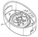
도 5는 조립되기 전의 캡 조립체의 사시도,
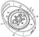
도 6은 조립된 후의 캡 조립체의 사시도,
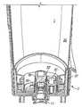
도 7은 용기 목과 캡 조립체 사이의 결합 상태를 도시한 단면도,
도 8은 부러지기 쉬운 부재를 구비한 캡의 사시도,
도 9는 용기가 캡에서 제거된 후를 도시한 도 7의 유사도,
도 10은 부러지기 쉬운 부재가 부러진 후를 도시한 도 8의 유사도,
도 11은 제2리필 유닛의 캡의 분해 사시도,
도 12는 조립된 캡을 도시한 도 11의 유사도,
도 13은 제2실시예의 압력 방출 밸브를 도시한 단면도,
도 14는 공기가 유동되도록 개방된 형태의 압력 방출 밸브를 도시한 도 13의 유사도,
도 15는 디스펜서의 제3리필 유닛을 도시한 도 4의 유사도,
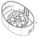
도 16은 제3리필 유닛의 캡을 도시한 도 5의 유사도,
도 17은 조립된 제3리필 유닛의 캡을 도시한 도 6의 유사도,
도 18은 제3리필 유닛을 도시한 도 7의 유사도.Hereinafter, a dispenser and a refill unit according to the present invention will be described with reference to the accompanying drawings.
1 is a sectional view of a dispenser,
Figure 2 is a cross-sectional view of a refill unit that was introduced into the dispenser but not combined,
Figure 3 shows the similarity of Figure 2 showing the refill unit in the intermediate position,
Figure 4 shows the similarity of Figure 3 illustrating the refill unit in its fully engaged position,
Figure 5 is a perspective view of the cap assembly before assembly,
Figure 6 is a perspective view of the cap assembly after assembly,
7 is a sectional view showing a state of engagement between the container neck and the cap assembly,
Figure 8 is a perspective view of a cap with a breakable member,
Figure 9 shows the similarity of Figure 7 after the container is removed from the cap,
Figure 10 shows the similarity of Figure 8 after breaking of a breakable member,
11 is an exploded perspective view of the cap of the second refill unit,
Figure 12 shows the similarity of Figure 11, showing the assembled cap,
13 is a cross-sectional view showing the pressure relief valve of the second embodiment,
Fig. 14 is a view similar to Fig. 13 showing a pressure relief valve of a type in which air is allowed to flow,
Fig. 15 shows the similarity of Fig. 4 showing the third refill unit of the dispenser,
Fig. 16 is a view similar to Fig. 5 showing the cap of the third refill unit,
17 shows the similarity of FIG. 6 showing the cap of the assembled third refill unit,
Figure 18 is a similarity view of Figure 7 showing a third refill unit.
디스펜서는 일반적으로 가정용으로 적합한 손을 사용하지 않고 이용할 수 있는 디스펜서이다. 디스펜서는 주로 액체 비누를 분배하지만, 예를 들면 핸드 크림, 바디 로션, 수분 크림, 얼굴 크림, 샴푸, 샤워 젤, 손 세정제, 면도 크림, 주방용 세제, 치약, 여드름 치료 크림, 표면 세척제 또는 알콜 젤과 같은 살균제 등의 (이상적으로 물보다 더 큰 점도를 갖는) 다른 액체 또는 반 액체 상태의 제품들을 분배하는데 이용될 수도 있다.A dispenser is a dispenser that can be used without using a hand suitable for home use. The dispenser dispenses liquid soap mainly, but it can be dispensed with, for example, hand cream, body lotion, moisture cream, face cream, shampoo, shower gel, hand cleaner, shaving cream, dishwashing detergent, toothpaste, acne treatment cream, May be used to dispense other liquid or semi-liquid products (ideally having a viscosity greater than that of water), such as the same biocide.
디스펜서는 2개의 주요부, 즉 리필 유닛(1) 및 베이스 유닛(2)을 포함한다. 리필 유닛(1)은 분배될 액체의 저장 공간을 제공하고, 이하에 설명되는 것처럼 베이스 유닛(2)에 끼워진다.The dispenser includes two main parts, a refill unit (1) and a base unit (2). The
베이스 유닛은 리필 유닛으로부터 액체가 분배되는 접속부(3)를 구비한다. 접속부(3)는 분배관(4)과 연통된다. 펌프(5)는 분배관(4)을 따라 분배 헤드(6) 밖으로 정량의 액체가 배출되도록 선택적으로 작동될 수 있다.The base unit has a connection portion (3) through which liquid is dispensed from the refill unit. The connection part (3) communicates with the distribution pipe (4). The pump 5 can be selectively operated to discharge a predetermined amount of liquid out of the dispensing head 6 along the dispensing tube 4. [
베이스 유닛은 디스펜서 부근에 사용자의 손이 존재하는지를 감지하기 위해 창(8)을 통하여 수신기(7B)로 적외선 빔을 전송하는 적외선 송신기(7A)를 구비한다. 제어 회로는 근접 센서로부터의 신호에 반응하여 펌프를 활성화시킨다. 도시된 센서는 브레이크 빔 센서(break beam sensor)지만, 반사 센서(reflective sensor)가 될 수도 있다. 적외선 센서가 도시되었지만, 용량성 센서(capacitive sensor)와 같은 다른 공지의 근접 센서가 이용될 수 있다. 장치는 주전원으로 구동되거나 배터리로 구동될 수 있다. 바람직하게는, 장치는 사용자가 레버를 눌러 제품을 교체하는 수동으로 작동되는 펌프 장치일 수 있다.The base unit includes an
이하, 도 2 내지 도 10을 참조하여, 리필 유닛(1)과 베이스 유닛(2) 사이의 접속부를 상세히 설명한다.Hereinafter, the connection between the
베이스 유닛(2)은 덮개(10)를 포함하고, 덮개(10)는 리필 유닛을 보호하고 지지하기 위해 리필 유닛의 상당 부분을 둘러싸고 있는 컵 형상의 하우징을 형성한다. 삽입 꼭지(11)는 덮개(10)의 베이스를 관통하여 돌출되고, 오링 씰(12)에 의해 덮개(10)에 밀폐된다. 삽입 꼭지는 상부면에 복수의 성벽 상단 형상부(13)를 구비한다. 제2오링 씰(14)은 성벽 상단 형상부(13)의 아래에서 삽입 꼭지(11)를 둘러싼다.The
리필 유닛(1)은 캡(21)이 고정되는 용기(20)를 구비한다. 용기(20)는 캡(21) 내부에서 환형의 플랜지(23)에 끼워져 밀폐되는 목(22)을 구비한다. 캡(21)은 캡의 외측 표면을 형성하는 상방으로 연장된 덮개(24)(도면에서 거꾸로 위치된 경우)를 구비한다. 덮개(24)로부터 내측으로 가면, 캡의 다음 형상은 일반적으로 덮개(24)와 동축을 갖는 외측 환형 벽(25)이 된다.The
이것은 도 5 내지 도 10에 자세히 도시된다.This is illustrated in detail in Figs.
외측 환형 벽(25)은, 서로 번갈아 위치되고 각각 도 5, 6, 8, 10에 도시된 원의 대략 1/4 정도로 연장된 한 쌍의 유지 부재(26)와 한 쌍의 지지 부재(27)로 구성된다. 지지 부재들(27)의 단면은 도 2에 도시된 것과 같다. 이 부재들은 캡의 하부 벽으로부터 직접 연장되고, 옆으로 나란하며, 상부 경사면(28)을 구비한다. 유지 부재들(26)의 단면은 도 7 및 도 9에 도시된다. 지지 부재들(27)과는 다르게, 유지 부재들(26)은 캡의 벽에 고정되지 않는다. 대신, 유지 부재들(26)은 양단부가 도 6 및 도 8에 잘 도시된 부러지기 쉬운 부재들(26)에 의해 지지 부재들(27)에 고정된다. 유지 부재들(26)은 옆으로 나란하고, 도 7 및 도 9에 도시된 상부 경사면(35)을 구비한다.The outer
도 7 및 도 9에 도시된 것처럼, 용기의 목(22)은 환형 벽(25)의 경사면들(28, 35)과 상호 보완적인 외측 경사면(36)을 구비한다. 외측 경사면(36) 뒤에는 용기(20)의 주 몸체와 대향하는 단턱(37)이 있다. 외측 경사면(36)과 단턱(37)은 유지 부재들(26) 부근에만 존재하고, 지지 부재들(27) 부근에는 존재하지 않는다. 지지 부재들(27)과 인접한 목(22)은 도 2에 도시된 것과 같이 옆으로 나란한 구성을 갖는다.7 and 9, the
용기(20)를 캡(21)에 삽입하기 위해, 용기(20)는 가압되어 용기의 목이 환형 플랜지(23)에 끼워진다. 용기의 외측 경사면(36)은 경사면들(28, 35)과 협력하여, 도 7에 도시된 것처럼 단턱(37)이 유지 부재들(26) 뒤에 끼워져 위치될 때까지 유지 부재들(26)들이 방사상 외측방향으로 이동되도록 한다. 용기(20)가 캡(21)에서 빠질 때, 단턱(37)이 유지 부재들(26)과 접촉되어 힘을 가하고, 이로 인해 부러지기 쉬운 부재들(29)이 파손되어 유지 부재들(26)은 도 9 및 도 10에 도시된 것처럼 캡(21)으로부터 분리된다. 이러한 경우가 발생하면, 용기의 캡을 유지하는 것이 더 이상 불가능하고, 따라서 리필 유닛(1)을 계속 사용할 수 없다.To insert the
뚜껑으로부터 완전히 분리되도록 하기 위해, 유지 부재들(26) 모두가 필요하지 않다는 것을 알아야 한다. 유지 부재들 중 하나만이 분리될 수 있고, 또는 유지 부재들 중 하나 또는 2개 모두가 유지 부재들이 용기의 목과 더 이상 체결되지 않는 위치로 간단하게 이동될 수 있다.To ensure complete separation from the lid, it should be noted that not all of the retaining
다시 도 2 내지 도 4를 참조하여, 이하에 액체 배출구 및 해당 밸브를 설명한다.Referring again to Figs. 2 to 4, the liquid outlet and the corresponding valve will be described below.
저장 공간으로부터의 액체 배출구는 중심 개구(31)를 둘러싼 환형 벽(30)을 구비한다. 환형 벽(30)의 상부에는 배출 밸브 요소(33)용 밸브 시트를 제공하는 경사면(32)(도 4 참조)이 있다. 경사면(32)은 U자 컵 형상 부재의 형태로 도시되지만, 동시에 고체 부재 또는 중공 볼 형태의 부재일 수 있다. 배출 밸브 요소(33)는 복수의 바이어싱(biasing) 요소들(34)에 의해 폐쇄된 위치로 치우쳐져 있다. 바이어싱 요소들(34)은 그 상측 단부가 밸브 요소(33)의 상부를 향하여 부착되고, 그 하측 단부들이 환형 벽(30)의 방사상 외측 및 환형 벽(33)의 상부 아래에 부착된다. 바이어싱 요소들(34)은 바람직하게는 밸브 요소(33)와 일체로 형성된다.The liquid outlet from the storage space has an annular wall (30) surrounding the central opening (31). Above the
도 2 내지 도 4에 도시된 것처럼, 리필 유닛(1)은 베이스 유닛(2)으로 하강하고, 삽입 꼭지(11)는 도 3에 도시된 것처럼 밸브 요소(33)의 하면에 체결된다. 또한 리필 유닛의 하부로의 이동은 밸브 요소(33)가 시트로부터 상승하도록 하고, 또한 오링(14)이 환형 벽(30)과 밀봉 결합되도록 한다. 밸브 요소(33)는 도 4에 도시된 위치로 상승한다. 이 위치에서, 용기(20) 안의 액체는 바이어싱 요소들(34) 주변으로 흐를 수 있고, 성벽 상단 형상부(13)를 통해 삽입 꼭지로 진입함으로써 베이스 유닛(2)으로 유입된다. 액체는 오링 씰(14)에 의해 삽입 꼭지(11)와 환형 벽(30) 사이에서 누수가 방지된다. 이러한 구성은 리필 유닛의 충진 높이에 상관없이 사용자가 리필 유닛을 간단하고 문제없이 삽입할 수 있도록 한다.2 to 4, the
리필 유닛을 제거하기 위해, 소비자는 베이스 유닛 밖으로 리필 유닛을 들어올리고, 그 결과 바이어싱 요소(34)가 밸브 요소(33)를 시트(32)로 복귀시킨다. 이러한 이동 중에, 삽입 꼭지(22)와 환형 벽(30) 사이의 밀봉은 오링 씰(14)에 의해 유지된다. 그리고, 다 쓴 리필 유닛은 상기한 절차를 따라 새로운 리필 유닛으로 교체된다.To remove the refill unit, the consumer lifts the refill unit out of the base unit, so that the biasing
캡은 한 쌍의 압력 방출 밸브(40)를 구비한다. 이들 각각은 캡(21)과 일체로 되어 있는 환형 보스(41)에 의해 형성된다. 압력 방출 밸브 요소(42)는 환형 보스(41)의 상부에 안착되고, (예를 들면 도 5에 도시된 것처럼) 한 쌍의 바이어싱 요소(43)에 의해 제자리에 치우쳐져 있다. 탄성력(biassing force)은 정상 조건 하에서 압력 방출 밸브 요소(42)가 보스(41)에 기밀 씰을 형성하도록 한다. 그러나, 용기(20) 내부의 압력이 특정 수준 이하로 떨어지면, 압력 방출 밸브 요소(42) 건너편의 압력차는 바이어싱 요소(43)에 의해 가해지는 힘을 극복하고, 용기(20) 안으로 공기가 유입되도록 할 만큼이 된다. 이것은 압력차를 감소시켜서 유체의 누수없이 기밀 씰을 복구한다.The cap has a pair of pressure relief valves (40). Each of which is formed by an
각각의 압력 방출 밸브(40)는 환형 장벽(44)으로 둘러싸이고, 환형 장벽(44)은 환형 벽(30)의 상부 높이의 축방향 위에 있는 높이로 축방향으로 연장된다. 따라서, 밸브 요소(33)가 개방되면, 방출 밸브(40)로 유입된 공기는 배출되는 유체 스트림에 합류되지 않을 것이다. 실제로, 이것은 방출 밸브가 배출구에 인접하게 위치될 수 있다는 것을 의미하고, 따라서 더욱 콤팩트한 캡을 구성할 수 있다. 2개의 방출 밸브들이 도시되어 있지만, 1개의 밸브, 또는 필요하다면 2개 이상의 밸브들이 구비될 수 있다.Each
캡이 조립되는 방식이 도 5 및 도 6에 도시되어 있다.The manner in which the cap is assembled is shown in Figures 5 and 6.
조립체는 캡(21), 밸브 플레이트(45) 및 고정 플레이트(46)를 포함하는 세 부분으로 된 구조이다. 캡은 환형 플랜지(23), 환형 벽(25) 및 환형 보스들(41)을 포함하는 다수의 몰드 형상을 갖는다. 또한, 캡(21)은 복수의 고정 기둥들(47)을 구비한다.The assembly is a three-part structure comprising a
밸브 플레이트(45)는 탄성 중합체 물질이고, 밸브 요소(33), 바이어싱 요소(34), 방출 밸브 요소(42) 및 바이어싱 요소들(43)과 일체로 형성된다. 밸브 플레이트는 고정 기둥들(47)과 대응되는 복수의 로케이팅 홀들(48)을 구비한다.
고정 플레이트(46)는 경질 플라스틱 물질이고, 환형 장벽(44)과 일체로 형성된다. 밸브 플레이트(45)와 마찬가지로, 고정 플레이트(46) 역시 고정 기둥들(47)과 대응되는 복수의 로케이팅 홀들(49)을 구비한다.The fixed
캡을 조립하기 위해, 도 6에 도시된 것처럼 부품들이 정확하게 정렬되도록 고정 기둥들이 로케이팅 홀들에 진입하는 상태로 3개의 부품들이 서로의 상부에 위치된다. 그리고 고정 기둥들을 고정 플레이트(46)에 고정시키기 위해 고정 기둥들(47)의 상부에 열 또는 접착제가 적용된다. 따라서 탄성 중합체 밸브 플레이트(45)는 밸브 요소들(33, 42)을 제자리에 유지하는 고정 플레이트(46)와 캡(21) 사이에 끼워진다.To assemble the cap, three parts are placed on top of each other with the fixing posts entering the locating holes so that the parts are aligned exactly as shown in Fig. And heat or glue is applied to the upper portions of the fixing
이하, 도 11 내지 도 14를 참조하여 리필 유닛용 캡의 제2실시예를 설명한다.Hereinafter, a second embodiment of the cap for the refill unit will be described with reference to Figs. 11 to 14. Fig.
제2실시예의 배출 밸브 요소(33)의 구조는 본질적으로 제1실시예와 동일하므로, 제2실시예에 대해서 다시 설명하지 않는다.Since the structure of the
도 11에 도시된 것처럼, 캡(21)은 환형 벽들(25, 30) 및 이하에 기술되는 압력 방출 밸브의 원뿔부(50)와 같이, 다수의 형상들과 일체로 몰딩된다. (이하에 더욱 자세히 기술될) 압력 방출 밸브의 탄성 립(53)은 밸브 플레이트(45)와 일체로 몰딩된다. 또한 고정 플레이트(46)는 방출 밸브용 차폐벽(57)을 구비한다. 이것은 도 2의 장벽(44)과 동등한 것이지만, 배출 밸브 요소(33)를 향하는 방출 밸브의 측면 주변으로만 연장된다. 장벽(44)과 차폐벽(57)은 두 실시예에서 교체 사용될 수 있다.As shown in Fig. 11, the
캡 조립체는 제1실시예와 동일한 방식으로 조립된다.The cap assembly is assembled in the same manner as in the first embodiment.
압력 방출 밸브(60)가 도 13 및 도 14에 도시되어 있다.A
밸브는 상기한 것처럼 캡(21)과 일체로 된 부분인 원뿔부(50)를 구비한다. 원뿔부(50)의 상부에는 원통 기둥(61)이 있다. 탄성 립(53)은 실질적으로 탄성 물질 밸브 플레이트(52)의 중공의 절두원뿔 형상 연장부이고, 이 연장부는 원뿔부(50)를 따라 연장되고 원뿔부(50)로부터 약간 이격되어 기둥(61)에 밀착된다. 적어도 하나의 공기 흡입구(62)(도 11에도 도시됨)가 원뿔부(50)의 벽을 관통하여 형성되고, 도 11에 도시된 것처럼 보통 때는 탄성 립(53)에 의해 덮여있다. 액체가 비어 용기(20)의 압력이 떨어지면, 탄성 립(53) 건너편의 압력차는 결국 도 14의 화살표로 도시된 것처럼 용기(20) 안으로 공기(A)가 유입될 수 있는 충분한 각도로 탄성 립(53)이 이동될 만큼이 될 것이다. 도 8에 도시된 탄성 립(53)이 원뿔부(50)로부터 상승하는 각도는 과장되어 있으며, 실제로 이 각도는 거의 감지할 수 없다는 것을 알아야 한다.The valve has a
기둥을 밀봉하는 대신, 탄성 립(53)은 원뿔부(50)를 밀봉할 것이다. 이 경우, 립은 도시된 것처럼 원뿔부로부터 이격되지 않는다. 그 대신, 실제로 립은 원뿔부에 자연스럽게 치우쳐지도록 원뿔부(50)의 각도보다 작은 경사각을 갖는다.Instead of sealing the column, the
이하, 도 15 내지 도 18을 참조하여 리필 유닛의 제3실시예를 설명한다. 제3실시예는 제1실시예와 거의 동일하고, 여기서는 중요한 차이점만 설명한다.Hereinafter, a third embodiment of the refill unit will be described with reference to FIGS. 15 to 18. FIG. The third embodiment is almost the same as the first embodiment, and only important differences are described here.
도 15에 도시된 것처럼, 배출 밸브 요소(33')가 다르게 형성되어 있다. 이 경우, 밸브가 환형 벽을 밀봉하는 것을 돕기 위해 폐쇄될 때 환형 벽(30) 내부에 끼워지는 소경부(60)가 존재한다.As shown in Fig. 15, the discharge valve element 33 'is formed differently. In this case, there is a
한 쌍의 압력 방출 밸브(40)는 하나의 통상적인 우산 밸브(umbrella valve)(61)로 대체되어 있다.The pair of
부러지기 쉬운 부재들(29)을 구비한 유지 부재들(26)은 서로 이격되어 있는 복수의 단턱들(62)로 대체되어 있고, 이 단턱들(62)은 도 18에 도시된 것처럼 용기(20)의 목에서 상호 보완적인 단턱들(63)과 결합된다. 플랜지(64)에 의해 용기 목의 내측 굴절이 방지된다. 도 18에 도시된 것처럼 위치되면, 단턱들 사이의 결합력은 모든 실질적인 목적을 위해 캡이 용기로부터 이탈되는 것을 방지할 만큼 강하다. 이것은 도 16 및 도 17에 도시된 것처럼 캡의 키 구성(64)에 의해 가능해지고, 키 구성(64)은 캡(21)과 용기(20) 사이의 상대 회전을 방지하기 위해 용기의 상호보완적인 돌출부(미도시)와 체결된다.The retaining
Claims (18)
Translated fromKorean상기 리필 유닛은 상기 리필 유닛 안으로 돌출되고 상기 리필 유닛의 배출구를 형성하는 환형 벽을 포함하고,
상기 환형 벽은 상기 환형 벽 상에 치우쳐져 있는 밸브 요소에 의해 최내단부가 폐쇄될 수 있고,
상기 베이스 유닛은 중공의 삽입 꼭지 및 상기 삽입 꼭지의 상부를 둘러싸고 상기 삽입 꼭지로부터 이격되어 있는 환형 씰을 포함하고,
상기 리필 유닛을 상기 베이스 유닛에 삽입하면, 상기 삽입 꼭지가 상기 환형 벽에 진입하고 상기 삽입 꼭지가 상기 밸브 요소를 상기 환형 벽으로부터 들어올려, 상기 리필 유닛으로부터 상기 삽입 꼭지의 상부 및 상기 밸브 요소의 바닥 중 적어도 하나에 형성된 적어도 하나의 절개부를 거쳐 상기 중공의 삽입 꼭지로 흘러내리는 유동 경로를 형성하며, 상기 환형 씰이 상기 삽입 꼭지와 상기 환형 벽 사이를 밀봉하고,
상기 밸브 요소는 적어도 하나의 탄성 부재에 의해 상기 환형 벽으로 치우쳐 있으며,
상기 탄성 부재 또는 각각의 탄성 부재는 상기 리필 유닛의 캡에 고정된 주변의 밸브 플레이트로 연장된 것을 특징으로 하는 디스펜서.
A base unit having an operating mechanism for dispensing liquid, and a refill unit that can be inserted into the base unit in an inverted form so that an outlet is located at the lowermost position for supplying liquid to the base unit,
Wherein the refill unit comprises an annular wall protruding into the refill unit and defining an outlet of the refill unit,
The annular wall may be closed at its innermost end by a valve element biased on the annular wall,
The base unit including a hollow insertion cap and an annular seal surrounding and spaced from the insertion cap,
Inserting the refill unit into the base unit causes the inserting faucet to enter the annular wall and the inserting cap to lift the valve element from the annular wall so that from the refill unit to the top of the inserting cap and the bottom of the valve element The annular seal defining a flow path through the at least one incision formed in at least one of the hollow insertion noses, the annular seal sealing between the insertion nip and the annular wall,
The valve element being biased by the annular wall by at least one resilient member,
Wherein the elastic member or each resilient member is extended to a peripheral valve plate fixed to a cap of the refill unit.
상기 적어도 하나의 탄성 부재는 일단이 상기 밸브 요소에 결합되고, 타단이 상기 환형 벽의 최내단부의 방사상 외측 및 아래의 위치에 결합되고,
상기 탄성 부재 또는 각각의 탄성 부재는, 상기 밸브 요소가 상기 환형 벽으로부터 상승되면, 상기 밸브 요소와 상기 환형 벽 사이에 유동 경로가 형성되도록 구성된 것을 특징으로 하는 디스펜서.
The method according to claim 1,
Wherein the at least one resilient member is coupled at one end to the valve element and at the other end to a radially outer and lower position of the innermost end of the annular wall,
Wherein the resilient member or each resilient member is configured to form a flow path between the valve element and the annular wall when the valve element is lifted from the annular wall.
상기 유동 경로를 형성하기 위하여 복수의 탄성 요소들이 상기 탄성 요소들 사이에 틈새를 갖도록 배열되어 있는 것을 특징으로 하는 디스펜서.
The method of claim 3,
And a plurality of elastic elements are arranged to have a gap between the elastic elements to form the flow path.
상기 밸브 요소는 상기 탄성 부재 또는 각각의 탄성 부재와 일체로 제조된 것을 특징으로 하는 디스펜서.
The method of claim 3,
Wherein the valve element is manufactured integrally with the elastic member or each elastic member.
상기 밸브 플레이트는 상기 캡과 고정 플레이트 사이에 끼워지는 것을 특징으로 하는 디스펜서.
The method according to claim 1,
Wherein the valve plate is sandwiched between the cap and the stationary plate.
상기 캡, 밸브 플레이트, 고정 플레이트를 서로에 대해 설치하기 위하여, 상기 캡, 밸브 플레이트 또는 고정 플레이트 중 하나에 1개 또는 그 이상의 고정 기둥들이 구비된 것을 특징으로 하는 디스펜서.
8. The method of claim 7,
Wherein one or more fixed posts are provided on one of said cap, valve plate, or stationary plate to provide said cap, valve plate, and stationary plate relative to each other.
상기 리필 유닛은 물보다 큰 점도를 갖는 액체로 채워진 것을 특징으로 하는 디스펜서.
The method according to claim 1,
Wherein the refill unit is filled with a liquid having a viscosity greater than water.
상기 리필 유닛은 사용 중에 최하단부인 일단에 개구를 포함하고,
상기 개구는 상기 리필 유닛으로 돌출되고 환형 벽에 치우쳐진 밸브 요소에 의해 최내단부가 폐쇄될 수 있는 상기 환형 벽을 포함하고,
상기 밸브 요소는, 일단이 상기 밸브 요소에 결합되고 타단이 상기 환형 벽의 최내단부의 방사상 외측 및 아래의 위치에 결합된 적어도 하나의 탄성 부재에 의해 치우쳐지고,
상기 탄성 부재 또는 각각의 탄성 부재는 상기 밸브 요소가 상기 환형 벽으로부터 상승되면 상기 밸브 요소와 상기 환형 벽 사이에 유동 경로가 형성되도록 구성되며,
상기 탄성 부재 또는 각각의 탄성 부재는 상기 리필 유닛의 캡에 고정된 주변의 밸브 플레이트로 연장된 것을 특징으로 하는 리필 유닛.
As a refill unit for a dispenser,
The refill unit includes an opening at one end which is the lowermost end during use,
Said opening comprising said annular wall protruding into said refill unit and being capable of being closed at its innermost end by a valve element biased towards said annular wall,
Wherein the valve element is biased by at least one resilient member, one end of which is coupled to the valve element and the other end is coupled radially outwardly and downwardly of the innermost end of the annular wall,
Wherein the resilient member or each resilient member is configured to form a flow path between the valve element and the annular wall when the valve element is lifted from the annular wall,
Wherein the elastic member or each elastic member extends to a peripheral valve plate fixed to the cap of the refill unit.
상기 유동 경로를 형성하기 위하여 복수의 탄성 요소들이 상기 탄성 요소들 사이에 틈새를 갖도록 배열되어 있는 것을 특징으로 하는 리필 유닛.
11. The method of claim 10,
Wherein a plurality of elastic elements are arranged to have a gap between the elastic elements so as to form the flow path.
상기 밸브 요소는 상기 탄성 부재 또는 각각의 탄성 부재와 일체로 제조된 것을 특징으로 하는 리필 유닛.
11. The method of claim 10,
Wherein the valve element is made integrally with the elastic member or each elastic member.
상기 밸브 플레이트는 상기 캡과 고정 플레이트 사이에 끼워진 것을 특징으로 하는 리필 유닛.
11. The method of claim 10,
Wherein the valve plate is sandwiched between the cap and the stationary plate.
상기 캡, 밸브 플레이트, 고정 플레이트를 서로에 대해 설치하기 위하여, 상기 캡, 밸브 플레이트 또는 고정 플레이트 중 하나에 1개 또는 그 이상의 고정 기둥들이 구비된 것을 특징으로 하는 리필 유닛.
15. The method of claim 14,
Wherein one of the cap, the valve plate, or the fixing plate is provided with one or more fixing posts for installing the cap, the valve plate, and the fixing plate relative to each other.
상기 개구는 액체 배출구이고, 상기 밸브 요소는 액체 배출 밸브 요소인 것을 특징으로 하는 리필 유닛.
11. The method of claim 10,
Wherein the opening is a liquid outlet and the valve element is a liquid discharge valve element.
상기 개구는 공기 배출구이고, 상기 밸브 요소는 공기 배출 밸브 요소인 것을 특징으로 하는 리필 유닛.
11. The method of claim 10,
Wherein the opening is an air outlet and the valve element is an air outlet valve element.
Applications Claiming Priority (2)
| Application Number | Priority Date | Filing Date | Title |
|---|---|---|---|
| GBGB0820981.9AGB0820981D0 (en) | 2008-11-17 | 2008-11-17 | Dispenser and refill unit |
| GB0820981.9 | 2008-11-17 |
Publications (2)
| Publication Number | Publication Date |
|---|---|
| KR20110086127A KR20110086127A (en) | 2011-07-27 |
| KR101601190B1true KR101601190B1 (en) | 2016-03-08 |
Family
ID=40194738
Family Applications (1)
| Application Number | Title | Priority Date | Filing Date |
|---|---|---|---|
| KR1020117012401AExpired - Fee RelatedKR101601190B1 (en) | 2008-11-17 | 2009-11-17 | Dispenser and refill unit |
Country Status (14)
| Country | Link |
|---|---|
| US (2) | US8662356B2 (en) |
| EP (2) | EP3431439A1 (en) |
| JP (1) | JP5425223B2 (en) |
| KR (1) | KR101601190B1 (en) |
| CN (1) | CN102216200B (en) |
| AU (1) | AU2009315391B2 (en) |
| BR (1) | BRPI0921551B1 (en) |
| CA (1) | CA2743259A1 (en) |
| GB (1) | GB0820981D0 (en) |
| MX (1) | MX2011005086A (en) |
| MY (1) | MY156557A (en) |
| RU (1) | RU2531725C2 (en) |
| WO (1) | WO2010055314A1 (en) |
| ZA (1) | ZA201103449B (en) |
Families Citing this family (53)
| Publication number | Priority date | Publication date | Assignee | Title |
|---|---|---|---|---|
| GB0820981D0 (en)* | 2008-11-17 | 2008-12-24 | Reckitt & Colman Overseas | Dispenser and refill unit |
| GB0820984D0 (en)* | 2008-11-17 | 2008-12-24 | Reckitt & Colman Overseas | A bottle with a tamper-proof cap |
| KR101802912B1 (en)* | 2009-10-09 | 2017-11-29 | 다니엘 파이 | Device with co-molded closure, one-way valve and variable-volume storage chamber, and related method |
| GB201007238D0 (en)* | 2010-04-30 | 2010-06-16 | Reckitt & Colman Overseas | A liquid delivery system |
| US20120111884A1 (en)* | 2010-10-21 | 2012-05-10 | Chun Kwong Choi | Automatic soap dispenser with notification function |
| GB2484935A (en) | 2010-10-26 | 2012-05-02 | Reckitt Benckiser Llc | Container with frangible device interface |
| GB201018005D0 (en)* | 2010-10-26 | 2010-12-08 | Reckitt Benckiser Inc | Dispenser for a foaming liquid composition |
| GB201020841D0 (en) | 2010-12-09 | 2011-01-19 | Reckitt & Colman Overseas | Dispenser for a foaming liquid composition with improved foam recovery feature |
| GB201104525D0 (en) | 2011-03-17 | 2011-05-04 | Reckitt & Colman Overseas | Dispenser and refill unit |
| US8616420B2 (en) | 2011-12-15 | 2013-12-31 | The Dial Corporation | Bottle closure with breakaway skirt for non-refillable bottles |
| WO2013119874A2 (en) | 2012-02-08 | 2013-08-15 | Simplehuman, Llc | Liquid dispensing units |
| GB201202578D0 (en) | 2012-02-15 | 2012-03-28 | Reckitt Benckiser Llc | Dispenser and refill unit and dispensing methods |
| US20130221032A1 (en)* | 2012-02-24 | 2013-08-29 | The Coca-Cola Company | Mechanical Dispensing System |
| US8851335B2 (en)* | 2012-04-17 | 2014-10-07 | Gojo Industries, Inc. | Water-driven dispensing systems employing concentrated product |
| US9038862B2 (en)* | 2013-01-23 | 2015-05-26 | Gojo Industries, Inc. | Pumps with container vents |
| US9271613B2 (en) | 2013-02-15 | 2016-03-01 | Delta Faucet Company | Electronic soap dispenser |
| US9648992B2 (en) | 2013-12-19 | 2017-05-16 | Gojo Industries, Inc. | Pumps with vents to vent inverted containers and refill units having non-collapsing containers |
| US10189038B2 (en) | 2013-12-20 | 2019-01-29 | Toaster Labs, Inc. | Inductively heatable fluid reservoir for various fluid types |
| US10144032B2 (en) | 2013-12-20 | 2018-12-04 | Toaster Labs, Inc. | Inductively heatable fluid reservoir |
| US10098510B2 (en) | 2013-12-20 | 2018-10-16 | Toaster Loabs, Inc. | Pneumatically driven fluid dispenser |
| US10433372B2 (en) | 2013-12-20 | 2019-10-01 | Toaster Labs, Inc. | Portable fluid warming device |
| US9801505B2 (en) | 2013-12-20 | 2017-10-31 | Toaster Labs, Inc. | Automatic fluid dispenser |
| US9974416B2 (en) | 2013-12-20 | 2018-05-22 | Toaster Labs, Inc. | Automatic heated fluid dispenser |
| US9578996B2 (en) | 2014-01-15 | 2017-02-28 | Gojo Industries, Inc. | Pumps with angled outlets, refill units and dispensers having angled outlets |
| JP6734780B2 (en) | 2014-02-24 | 2020-08-05 | ゴジョ・インダストリーズ・インコーポレイテッド | Non-vented collapsible container, refillable refill container, dispenser and refill unit |
| GB201404950D0 (en)* | 2014-03-19 | 2014-04-30 | Reckitt Benckiser Brands Ltd | Dispensing device |
| JP2016029795A (en)* | 2014-07-18 | 2016-03-03 | 株式会社半導体エネルギー研究所 | Semiconductor device, imaging device, and electronic apparatus |
| KR20170030630A (en)* | 2014-07-25 | 2017-03-17 | 에이비비 슈바이쯔 아게 | Refill-container for replenishing and/or reconditioning an insulation fluid contained in an insulation space of an electrical apparatus |
| US9596963B2 (en) | 2014-07-30 | 2017-03-21 | Gojo Industries, Inc. | Vented refill units and dispensers having vented refill units |
| US10517441B2 (en)* | 2014-08-27 | 2019-12-31 | Gojo Industries, Inc. | Energy harvesting for dispensing system |
| MY186715A (en) | 2014-10-02 | 2021-08-12 | Unilever Plc | Liquid dispenser with framed refill receiving bay |
| US9884336B2 (en)* | 2014-10-10 | 2018-02-06 | The Procter & Gamble Company | Multifunctional dispensing device for dispensing fluid compositions |
| GB2535239A (en) | 2015-02-13 | 2016-08-17 | Nerudia Ltd | System and apparatus |
| GB2535982A (en) | 2015-02-13 | 2016-09-07 | Nerudia Ltd | System and apparatus |
| US10076216B2 (en)* | 2015-02-25 | 2018-09-18 | Simplehuman, Llc | Foaming soap dispensers |
| CA2922625A1 (en) | 2015-03-06 | 2016-09-06 | Simplehuman, Llc | Foaming soap dispensers |
| USD773848S1 (en) | 2015-03-06 | 2016-12-13 | Simplehuman, Llc | Liquid dispenser cartridge |
| GB201517754D0 (en)* | 2015-10-07 | 2015-11-18 | Rieke Packaging Systems Ltd | Liquid dosing devices |
| GB2537471B (en)* | 2016-02-25 | 2017-09-06 | Packaging Innovation Ltd | A fluid coupling |
| AU2017276358B2 (en)* | 2016-06-08 | 2018-07-05 | Rick Soley | Sports hydration apparatus |
| NL2017109B1 (en) | 2016-07-05 | 2018-01-12 | Heineken Supply Chain Bv | Beverage dispensing assembly and beverage container |
| AU2017351946B2 (en) | 2016-10-28 | 2023-08-31 | Rb Health (Us) Llc | Feminine hygiene products |
| ES2857923T3 (en) | 2017-03-17 | 2021-09-29 | Simplehuman Llc | Soap pump |
| NL2018955B1 (en)* | 2017-05-19 | 2018-11-28 | Heineken Supply Chain Bv | Beverage dispensing assembly and beverage container |
| NL2018956B1 (en) | 2017-05-19 | 2018-11-28 | Heineken Supply Chain Bv | Beverage dispensing assembly and beverage container |
| WO2019074926A1 (en)* | 2017-10-09 | 2019-04-18 | Pathspot Technologies Inc. | Systems and methods for detection of contaminants on surfaces |
| US12285142B2 (en)* | 2019-09-03 | 2025-04-29 | Peter Bai | Dispenser system |
| USD962672S1 (en) | 2020-08-26 | 2022-09-06 | Simplehuman, Llc | Dispenser |
| USD967650S1 (en) | 2020-10-26 | 2022-10-25 | Simplehuman, Llc | Liquid dispenser |
| CA3147987A1 (en) | 2021-02-05 | 2022-08-05 | Simplehuman, Llc | Push-pump for dispensing soap or other liquids |
| US11759060B2 (en) | 2021-02-08 | 2023-09-19 | Simplehuman, Llc | Portable consumer liquid pump |
| US11641985B2 (en)* | 2021-04-13 | 2023-05-09 | Alo New York Llc | Modular fluid dispensing system |
| WO2024194982A1 (en)* | 2023-03-20 | 2024-09-26 | 株式会社Lixil | Liquid dispensing container |
Citations (1)
| Publication number | Priority date | Publication date | Assignee | Title |
|---|---|---|---|---|
| US5556005A (en) | 1995-01-09 | 1996-09-17 | Sprintvest Corporation Nv | Collapsible soap dispenser |
Family Cites Families (15)
| Publication number | Priority date | Publication date | Assignee | Title |
|---|---|---|---|---|
| FR2198559A5 (en)* | 1972-08-30 | 1974-03-29 | Seppic Sa | Removable liquid-soap dispenser - with polypropylene supply container |
| US4964544A (en)* | 1988-08-16 | 1990-10-23 | Bobrick Washroom Equipment, Inc. | Push up dispenser with capsule valve |
| US5031676A (en)* | 1988-09-30 | 1991-07-16 | Liqui-Box Corporation | Decap dispensing system for water cooler bottles |
| US5273083A (en)* | 1991-10-07 | 1993-12-28 | Ebtech, Inc. | Bottle cap and valve assembly for a bottled water station |
| US5232125A (en)* | 1991-10-08 | 1993-08-03 | Portola Packaging, Inc. | Non-spill bottle cap used with water dispensers |
| US5839614A (en)* | 1991-12-06 | 1998-11-24 | Aptar Group, Inc. | Dispensing package |
| CN2140353Y (en)* | 1992-12-29 | 1993-08-18 | 江鑫 | Valve assembly for infrared cleaner dispenser |
| US6269837B1 (en)* | 1998-11-09 | 2001-08-07 | The Procter & Gamble Company | Rechargeable dispensing system |
| US6276565B1 (en)* | 1999-05-11 | 2001-08-21 | Arichell Technologies, Inc. | Gas-driven liquid dispenser employing separate pressurized-gas source |
| US8237558B2 (en)* | 2007-03-30 | 2012-08-07 | University Health Network | Hand hygiene compliance system |
| US7898407B2 (en)* | 2007-03-30 | 2011-03-01 | Toronto Rehabilitation Institute | Hand hygiene compliance system |
| GB2449469B (en)* | 2007-05-23 | 2011-11-23 | Brightwell Dispensers Ltd | Coupling |
| GB0820981D0 (en)* | 2008-11-17 | 2008-12-24 | Reckitt & Colman Overseas | Dispenser and refill unit |
| GB0820984D0 (en)* | 2008-11-17 | 2008-12-24 | Reckitt & Colman Overseas | A bottle with a tamper-proof cap |
| US8245877B2 (en)* | 2009-07-22 | 2012-08-21 | Gotohti.Com Inc. | Dispenser with palm reader |
- 2008
- 2008-11-17GBGBGB0820981.9Apatent/GB0820981D0/ennot_activeCeased
- 2009
- 2009-11-17KRKR1020117012401Apatent/KR101601190B1/ennot_activeExpired - Fee Related
- 2009-11-17CACA2743259Apatent/CA2743259A1/ennot_activeAbandoned
- 2009-11-17MYMYPI2011002151Apatent/MY156557A/enunknown
- 2009-11-17AUAU2009315391Apatent/AU2009315391B2/enactiveActive
- 2009-11-17JPJP2011543808Apatent/JP5425223B2/enactiveActive
- 2009-11-17WOPCT/GB2009/002682patent/WO2010055314A1/enactiveApplication Filing
- 2009-11-17CNCN200980145568XApatent/CN102216200B/enactiveActive
- 2009-11-17BRBRPI0921551-4Apatent/BRPI0921551B1/enactiveIP Right Grant
- 2009-11-17USUS13/129,164patent/US8662356B2/enactiveActive
- 2009-11-17RURU2011124521/12Apatent/RU2531725C2/enactive
- 2009-11-17MXMX2011005086Apatent/MX2011005086A/enactiveIP Right Grant
- 2009-11-17EPEP18182502.7Apatent/EP3431439A1/ennot_activeCeased
- 2009-11-17EPEP09760264.3Apatent/EP2365933B1/enactiveActive
- 2011
- 2011-05-11ZAZA2011/03449Apatent/ZA201103449B/enunknown
- 2013
- 2013-11-22USUS14/087,433patent/US8998036B2/enactiveActive
Patent Citations (2)
| Publication number | Priority date | Publication date | Assignee | Title |
|---|---|---|---|---|
| US5556005A (en) | 1995-01-09 | 1996-09-17 | Sprintvest Corporation Nv | Collapsible soap dispenser |
| JP3739793B2 (en)* | 1995-01-09 | 2006-01-25 | デブ アイピー リミテッド | Foldable soap dispenser |
Also Published As
| Publication number | Publication date |
|---|---|
| BRPI0921551A2 (en) | 2016-03-08 |
| HK1163045A1 (en) | 2012-09-07 |
| GB0820981D0 (en) | 2008-12-24 |
| AU2009315391B2 (en) | 2013-06-13 |
| US20140084021A1 (en) | 2014-03-27 |
| JP2012508676A (en) | 2012-04-12 |
| US8998036B2 (en) | 2015-04-07 |
| WO2010055314A1 (en) | 2010-05-20 |
| RU2531725C2 (en) | 2014-10-27 |
| MY156557A (en) | 2016-02-26 |
| MX2011005086A (en) | 2011-07-29 |
| EP3431439A1 (en) | 2019-01-23 |
| US8662356B2 (en) | 2014-03-04 |
| AU2009315391A1 (en) | 2010-05-20 |
| CN102216200A (en) | 2011-10-12 |
| CN102216200B (en) | 2013-03-27 |
| ZA201103449B (en) | 2012-07-25 |
| CA2743259A1 (en) | 2010-05-20 |
| EP2365933B1 (en) | 2018-08-22 |
| RU2011124521A (en) | 2012-12-27 |
| KR20110086127A (en) | 2011-07-27 |
| BRPI0921551B1 (en) | 2019-06-18 |
| JP5425223B2 (en) | 2014-02-26 |
| EP2365933A1 (en) | 2011-09-21 |
| US20120097711A1 (en) | 2012-04-26 |
Similar Documents
| Publication | Publication Date | Title |
|---|---|---|
| KR101601190B1 (en) | Dispenser and refill unit | |
| KR101557085B1 (en) | A relief valve | |
| JP5368582B2 (en) | Bottle with foreign matter prevention cap | |
| KR20130079416A (en) | Kit comprising a liquid container and a refill device | |
| HK1163045B (en) | Dispenser and refill unit | |
| HK1163036B (en) | A relief valve,a container having the relief valve and a refill unit | |
| HK1163035B (en) | A bottle with a tamper-proof cap |
Legal Events
| Date | Code | Title | Description |
|---|---|---|---|
| PA0105 | International application | St.27 status event code:A-0-1-A10-A15-nap-PA0105 | |
| PG1501 | Laying open of application | St.27 status event code:A-1-1-Q10-Q12-nap-PG1501 | |
| PN2301 | Change of applicant | St.27 status event code:A-3-3-R10-R13-asn-PN2301 St.27 status event code:A-3-3-R10-R11-asn-PN2301 | |
| A201 | Request for examination | ||
| PA0201 | Request for examination | St.27 status event code:A-1-2-D10-D11-exm-PA0201 | |
| E902 | Notification of reason for refusal | ||
| PE0902 | Notice of grounds for rejection | St.27 status event code:A-1-2-D10-D21-exm-PE0902 | |
| E13-X000 | Pre-grant limitation requested | St.27 status event code:A-2-3-E10-E13-lim-X000 | |
| P11-X000 | Amendment of application requested | St.27 status event code:A-2-2-P10-P11-nap-X000 | |
| P13-X000 | Application amended | St.27 status event code:A-2-2-P10-P13-nap-X000 | |
| E701 | Decision to grant or registration of patent right | ||
| PE0701 | Decision of registration | St.27 status event code:A-1-2-D10-D22-exm-PE0701 | |
| GRNT | Written decision to grant | ||
| PR0701 | Registration of establishment | St.27 status event code:A-2-4-F10-F11-exm-PR0701 | |
| PR1002 | Payment of registration fee | St.27 status event code:A-2-2-U10-U12-oth-PR1002 Fee payment year number:1 | |
| PG1601 | Publication of registration | St.27 status event code:A-4-4-Q10-Q13-nap-PG1601 | |
| FPAY | Annual fee payment | Payment date:20190129 Year of fee payment:4 | |
| PR1001 | Payment of annual fee | St.27 status event code:A-4-4-U10-U11-oth-PR1001 Fee payment year number:4 | |
| PN2301 | Change of applicant | St.27 status event code:A-5-5-R10-R11-asn-PN2301 | |
| PN2301 | Change of applicant | St.27 status event code:A-5-5-R10-R14-asn-PN2301 | |
| FPAY | Annual fee payment | Payment date:20200129 Year of fee payment:5 | |
| PR1001 | Payment of annual fee | St.27 status event code:A-4-4-U10-U11-oth-PR1001 Fee payment year number:5 | |
| PR1001 | Payment of annual fee | St.27 status event code:A-4-4-U10-U11-oth-PR1001 Fee payment year number:6 | |
| PR1001 | Payment of annual fee | St.27 status event code:A-4-4-U10-U11-oth-PR1001 Fee payment year number:7 | |
| PC1903 | Unpaid annual fee | St.27 status event code:A-4-4-U10-U13-oth-PC1903 Not in force date:20230303 Payment event data comment text:Termination Category : DEFAULT_OF_REGISTRATION_FEE | |
| PC1903 | Unpaid annual fee | St.27 status event code:N-4-6-H10-H13-oth-PC1903 Ip right cessation event data comment text:Termination Category : DEFAULT_OF_REGISTRATION_FEE Not in force date:20230303 |