KR101600947B1 - Data transfer across power domains - Google Patents
Data transfer across power domainsDownload PDFInfo
- Publication number
- KR101600947B1 KR101600947B1KR1020157016769AKR20157016769AKR101600947B1KR 101600947 B1KR101600947 B1KR 101600947B1KR 1020157016769 AKR1020157016769 AKR 1020157016769AKR 20157016769 AKR20157016769 AKR 20157016769AKR 101600947 B1KR101600947 B1KR 101600947B1
- Authority
- KR
- South Korea
- Prior art keywords
- stage
- circuit
- power
- tier
- level shifter
- Prior art date
- Legal status (The legal status is an assumption and is not a legal conclusion. Google has not performed a legal analysis and makes no representation as to the accuracy of the status listed.)
- Expired - Fee Related
Links
Images


Classifications
- G06F17/5072—
- G—PHYSICS
- G06—COMPUTING OR CALCULATING; COUNTING
- G06F—ELECTRIC DIGITAL DATA PROCESSING
- G06F1/00—Details not covered by groups G06F3/00 - G06F13/00 and G06F21/00
- G06F1/26—Power supply means, e.g. regulation thereof
- G06F1/32—Means for saving power
- G—PHYSICS
- G06—COMPUTING OR CALCULATING; COUNTING
- G06F—ELECTRIC DIGITAL DATA PROCESSING
- G06F1/00—Details not covered by groups G06F3/00 - G06F13/00 and G06F21/00
- G06F1/26—Power supply means, e.g. regulation thereof
- G06F1/32—Means for saving power
- G06F1/3203—Power management, i.e. event-based initiation of a power-saving mode
- G06F1/3234—Power saving characterised by the action undertaken
- G06F1/3287—Power saving characterised by the action undertaken by switching off individual functional units in the computer system
- G06F17/5068—
- G—PHYSICS
- G06—COMPUTING OR CALCULATING; COUNTING
- G06F—ELECTRIC DIGITAL DATA PROCESSING
- G06F30/00—Computer-aided design [CAD]
- G06F30/30—Circuit design
- G06F30/39—Circuit design at the physical level
- G—PHYSICS
- G06—COMPUTING OR CALCULATING; COUNTING
- G06F—ELECTRIC DIGITAL DATA PROCESSING
- G06F30/00—Computer-aided design [CAD]
- G06F30/30—Circuit design
- G06F30/39—Circuit design at the physical level
- G06F30/392—Floor-planning or layout, e.g. partitioning or placement
- G—PHYSICS
- G06—COMPUTING OR CALCULATING; COUNTING
- G06F—ELECTRIC DIGITAL DATA PROCESSING
- G06F30/00—Computer-aided design [CAD]
- G06F30/30—Circuit design
- G06F30/39—Circuit design at the physical level
- G06F30/394—Routing
- G—PHYSICS
- G06—COMPUTING OR CALCULATING; COUNTING
- G06F—ELECTRIC DIGITAL DATA PROCESSING
- G06F30/00—Computer-aided design [CAD]
- G06F30/30—Circuit design
- G06F30/39—Circuit design at the physical level
- G06F30/398—Design verification or optimisation, e.g. using design rule check [DRC], layout versus schematics [LVS] or finite element methods [FEM]
- G—PHYSICS
- G11—INFORMATION STORAGE
- G11C—STATIC STORES
- G11C5/00—Details of stores covered by group G11C11/00
- G11C5/14—Power supply arrangements, e.g. power down, chip selection or deselection, layout of wirings or power grids, or multiple supply levels
- H—ELECTRICITY
- H01—ELECTRIC ELEMENTS
- H01L—SEMICONDUCTOR DEVICES NOT COVERED BY CLASS H10
- H01L23/00—Details of semiconductor or other solid state devices
- H01L23/52—Arrangements for conducting electric current within the device in operation from one component to another, i.e. interconnections, e.g. wires, lead frames
- H01L23/522—Arrangements for conducting electric current within the device in operation from one component to another, i.e. interconnections, e.g. wires, lead frames including external interconnections consisting of a multilayer structure of conductive and insulating layers inseparably formed on the semiconductor body
- H01L23/5226—Via connections in a multilevel interconnection structure
- H—ELECTRICITY
- H03—ELECTRONIC CIRCUITRY
- H03K—PULSE TECHNIQUE
- H03K19/00—Logic circuits, i.e. having at least two inputs acting on one output; Inverting circuits
- H03K19/0008—Arrangements for reducing power consumption
- G06F2217/62—
- G—PHYSICS
- G06—COMPUTING OR CALCULATING; COUNTING
- G06F—ELECTRIC DIGITAL DATA PROCESSING
- G06F30/00—Computer-aided design [CAD]
- G06F30/30—Circuit design
- G—PHYSICS
- G06—COMPUTING OR CALCULATING; COUNTING
- G06F—ELECTRIC DIGITAL DATA PROCESSING
- G06F30/00—Computer-aided design [CAD]
- G06F30/30—Circuit design
- G06F30/32—Circuit design at the digital level
- G06F30/327—Logic synthesis; Behaviour synthesis, e.g. mapping logic, HDL to netlist, high-level language to RTL or netlist
- G—PHYSICS
- G06—COMPUTING OR CALCULATING; COUNTING
- G06F—ELECTRIC DIGITAL DATA PROCESSING
- G06F30/00—Computer-aided design [CAD]
- G06F30/30—Circuit design
- G06F30/39—Circuit design at the physical level
- G06F30/396—Clock trees
- H—ELECTRICITY
- H01—ELECTRIC ELEMENTS
- H01L—SEMICONDUCTOR DEVICES NOT COVERED BY CLASS H10
- H01L2924/00—Indexing scheme for arrangements or methods for connecting or disconnecting semiconductor or solid-state bodies as covered by H01L24/00
- H01L2924/0001—Technical content checked by a classifier
- H01L2924/0002—Not covered by any one of groups H01L24/00, H01L24/00 and H01L2224/00
- Y—GENERAL TAGGING OF NEW TECHNOLOGICAL DEVELOPMENTS; GENERAL TAGGING OF CROSS-SECTIONAL TECHNOLOGIES SPANNING OVER SEVERAL SECTIONS OF THE IPC; TECHNICAL SUBJECTS COVERED BY FORMER USPC CROSS-REFERENCE ART COLLECTIONS [XRACs] AND DIGESTS
- Y02—TECHNOLOGIES OR APPLICATIONS FOR MITIGATION OR ADAPTATION AGAINST CLIMATE CHANGE
- Y02D—CLIMATE CHANGE MITIGATION TECHNOLOGIES IN INFORMATION AND COMMUNICATION TECHNOLOGIES [ICT], I.E. INFORMATION AND COMMUNICATION TECHNOLOGIES AIMING AT THE REDUCTION OF THEIR OWN ENERGY USE
- Y02D10/00—Energy efficient computing, e.g. low power processors, power management or thermal management
Landscapes
- Engineering & Computer Science (AREA)
- Physics & Mathematics (AREA)
- Theoretical Computer Science (AREA)
- Computer Hardware Design (AREA)
- General Engineering & Computer Science (AREA)
- General Physics & Mathematics (AREA)
- Geometry (AREA)
- Evolutionary Computation (AREA)
- Computing Systems (AREA)
- Power Engineering (AREA)
- Mathematical Physics (AREA)
- Architecture (AREA)
- Condensed Matter Physics & Semiconductors (AREA)
- Microelectronics & Electronic Packaging (AREA)
- Computer Networks & Wireless Communication (AREA)
- Design And Manufacture Of Integrated Circuits (AREA)
- Semiconductor Integrated Circuits (AREA)
- Logic Circuits (AREA)
- Power Sources (AREA)
- Semiconductor Memories (AREA)
- Metal-Oxide And Bipolar Metal-Oxide Semiconductor Integrated Circuits (AREA)
Abstract
Translated fromKoreanDescription
Translated fromKorean3535U.S.CU.S.C.§119 하에서의 우선권 주장Priority claim under §119
[0001] 본 특허 출원은:[0001] This patent application claims priority to:
2012년 11월 28일자로 출원되고, 본원의 양수인에게 양도되며, 여기서 본원에 인용에 의해 명시적으로 포함되는, 발명의 명칭이 "DATA TRANSFER ACROSS POWER DOMAINS"인 가특허 출원 제61/730,767호, 및Filed on November 28, 2012, assigned to the assignee hereof and hereby expressly incorporated herein by reference, are described in detail in
2012년 11월 28일자로 출원되고, 본원의 양수인에게 양도되며, 여기서 본원에 인용에 의해 명시적으로 포함되는, 발명의 명칭이 "CLOCK DISTRIBUTION NETWORK FOR 3D INTEGRATED CIRCUIT"인 가특허 출원 제61/730,755호No. 61 / 730,755, filed November 28, 2012, which is assigned to the assignee hereof and which is expressly incorporated herein by reference, is entitled " CLOCK DISTRIBUTION NETWORK FOR 3D INTEGRATED CIRCUIT & number
를 우선권으로 주장한다.
As a priority.
공동-계류중인 특허Co-pending patent출원들에 대한 참조Reference to Applications
[0002] 본 특허 출원은, 이하의 공동-계류중인 U.S 특허 출원(들)에 관한 것이다:[0002] This patent application relates to the following co-pending U.S. patent application (s):
2013년 3월 5일자로 출원되고, 본원의 양수인에게 양도되며, 본원에 인용에 의해 명시적으로 포함되는, 어토니 도켓 번호 제123412호를 갖는, Yang Du, Jing Xie 및 Kambiz Samadi에 의한 "MONOLITHIC 3D IC FLIP-FLOP DESIGN";Quot; MONOLITHIC " by Yang Du, Jing Xie, and Kambiz Samadi, having the Attorney Docket No. 123412, filed March 5, 2013, assigned to the assignee hereof and expressly incorporated herein by reference, 3D IC FLIP-FLOP DESIGN ";
2013년 3월 7일자로 출원되고, 본원의 양수인에게 양도되며, 본원에 인용에 의해 명시적으로 포함되는, 어토니 도켓 번호 제120600호를 갖는, Yang Du에 의한 "MONOLITHIC THREE DIMENSIONAL INTEGRATION OF SEMICONDUCTOR INTEGRATED CIRCUITS"; 및Quot; MONOLITHIC THREE DIMENSIONAL INTEGRATION OF SEMICONDUCTOR INTEGRATED " filed on March 7, 2013, assigned to the assignee hereof and having the Attorney Docket Number 120600, expressly incorporated herein by Yang Du CIRCUITS "; And
[****]자로 출원되고, 본원의 양수인에게 양도되며, 본원에 인용에 의해 명시적으로 포함되는, 어토니 도켓 번호 제124318호를 갖는, Kambiz Samadi, Shreepad Panth, Jing Xie 및 Yang Du에 의한 "CLOCK DISTRIBUTION NETWORK FOR 3D INTEGRATED CIRCUIT".
Kambiz Samadi, Shreepad Panth, Jing Xie, and Yang Du, having an Attorney Docket No. 124318, filed as [****], assigned to the assignee hereof and expressly incorporated herein by reference, "CLOCK DISTRIBUTION NETWORK FOR 3D INTEGRATED CIRCUIT ".
본example개시물의Initiation 분야 Field
[0003] 개시된 실시예들은 일반적으로, 집적 회로들 내에서 하나의 전력 도메인으로부터 다른 상이한 전력 도메인으로의 데이터의 효율적인 트랜스퍼에 관한 것이다. 더욱 구체적으로는, 개시된 실시예들은, 저전력의 집적 회로들 내에서 하나의 전력 도메인으로부터 다른 전력 도메인으로 데이터를 트랜스퍼하면서 면적 소모, 전력 소모, 기록 시간 딜레이, 전력 도메인들 간의 크로스-토크, 및 다른 성능 파라미터들을 최적화하기 위한 시스템들 및 방법들에 관한 것이다.[0003] The disclosed embodiments generally relate to efficient transfer of data from one power domain to another in the integrated circuits. More specifically, the disclosed embodiments provide a method and system for transferring data from one power domain to another power domain in low-power integrated circuits such as area consumption, power consumption, write time delay, cross-talk between power domains, To systems and methods for optimizing performance parameters.
[0004] 디지털 회로들에서, 배선(wire)의 2개의 로지컬 상태들은 보통 2개의 상이한 전압들로 나타난다. 배선 전압이 미리결정된 임계치 미만일 때, 배선 상의 신호는 "로우(low)"로 판독된다. 배선 전압이 미리결정된 임계치를 초과할 때, 배선상의 신호는 "하이(high)"로 판독된다. 로직 하이 전압은 종종 Vdd로 지칭되고, 로직 로우 전압은 종종 디지털 "접지"인 Vss로 지칭된다. 현대의 디지털 로직 시스템들에서, 상이한 Vdd 레벨들은 종종 시스템 성능 및 전력 소모를 관리하기 위해 상이한 기능 회로 블록들에 대해 활용된다. 예를 들어, 특정 회로 블록들은 다른 회로 블록들처럼 빠르게 동작할 필요는 없다. 따라서, 특정 회로 블록들에 대한 Vdd는 다른 회로 블록들에 대한 Vdd와는 상이한 레벨로 설정될 수 있다. 기능 회로 블록의 Vdd 레벨은 종종 회로 블록의 전력 도메인으로 지칭된다. 디지털 신호들이 하나의 전력 도메인에서 동작하는 회로 블록으로부터 다른 전력 도메인에서 동작하는 회로 블록으로 트랜스퍼될 때, 신호들은 하나의 전력 도메인으로부터 다른 도메인으로 컨버팅될 필요가 있다. 레벨 시프터 회로는, 하나의 전력 도메인으로부터의 신호들을 다른 전력 도메인으로 시프트하며, 전력 도메인 A에서 동작하는 기능 회로 블록과 전력 도메인 B에서 동작하는 기능 블록 사이의 인터페이스로서 종종 이용된다. 다수의 전력 도메인들을 제공하는 것은 또한 다수의 전력 레일들을 요구하여 집적 회로상에서의 전력 레일 물리적 라우팅 혼잡(power rail physical routing congestion)을 증가시킨다[0004] In digital circuits, two logical states of a wire usually appear as two different voltages. When the wiring voltage is below the predetermined threshold, the signal on the wiring is read as " low ". When the wiring voltage exceeds a predetermined threshold, the signal on the wiring is read as "high ". The logic high voltage is often referred to as Vdd and the logic low voltage is often referred to as Vss, which is a digital "ground. &Quot; In modern digital logic systems, different Vdd levels are often utilized for different functional circuit blocks to manage system performance and power consumption. For example, certain circuit blocks do not need to operate as fast as other circuit blocks. Thus, Vdd for particular circuit blocks may be set to a different level than Vdd for other circuit blocks. The Vdd level of the functional circuit block is often referred to as the power domain of the circuit block. When digital signals are transferred from a circuit block operating in one power domain to a circuit block operating in another power domain, the signals need to be converted from one power domain to another. The level shifter circuit shifts signals from one power domain to another power domain and is often used as an interface between a functional circuit block operating in power domain A and a functional block operating in power domain B. [ Providing multiple power domains also requires multiple power rails to increase the power rail physical routing congestion on the integrated circuit
[0005] 전력 소모 및 면적 효율은, 오늘날의 소형, 고속 그리고 고-성능의 모바일 애플리케이션들에서의 중대한 문제들이다. 소위 시스템-온-칩(SoC) 설계들에서, 전력 소모를 감소시키기 위한 통상적인 기법은 시스템을 상이한 전력 도메인들로 분할하는 것이다. 예를 들어, 대략적인(coarse) 레벨에서, 계산 로직 및 캐시는 그들 자신의 공급 전압들에서 동작하도록 설계될 수 있다. 다수의 프로세싱 코어들을 동일한 칩에 제공하는 시스템들(즉, 멀티-코어 시스템들)에서, 다수의 전력 도메인들은 각각의 코어에 대한 동적 전압 및 주파수 스케일링(DVFS; dynamic voltage and frequency scaling)을 가능하게 하기 위해 요구된다. 일반적으로, 더 정교한 입도의 전력 도메인들을 제공하는 것은, 시스템 전력을 효율적으로 감소시키는 것으로 알려져 있고, 파워 월 문제(power wall problem)를 해결하기 위한 매력적인 접근방식으로 고려된다. 앞서 설명된 바와 같이, 멀티-도메인 설계들은, 신뢰가능한 크로스 도메인 데이터 트랜스퍼를 보장하고 그리고 크로스 도메인 데이터 트래픽을 관리하기 위해 도메인 바운더리에 소정 타입의 레벨 시프터 회로를 요구한다. 그러나, 소형, 고속 그리고 고성능의 애플리케이션에 레벨 시프터 회로를 제공하기 위한 알려진 시도들은, 면적 소모, 전력 소모, 기록 시간 딜레이, 전력 레일 혼잡 등과 같은 다양한 성능 파라미터들에서의 비효율성들로 인해 비현실적이었다. 이러한 문제점들은, 정교한-입도의 멀티-전력 도메인 시스템 설계들의 광범위한 허용(widespread acceptance)을 방해해왔다.[0005] Power consumption and area efficiency are significant problems in today's small, high speed and high-performance mobile applications. In so-called system-on-chip (SoC) designs, a common technique for reducing power consumption is to partition the system into different power domains. For example, at a coarse level, the calculation logic and the cache may be designed to operate at their own supply voltages. In systems that provide multiple processing cores on the same chip (i.e., multi-core systems), multiple power domains enable dynamic voltage and frequency scaling (DVFS) for each core . In general, providing power domains with more sophisticated granularity is known to efficiently reduce system power and is considered an attractive approach to solving power wall problems. As described above, multi-domain designs require some type of level shifter circuitry at the domain boundary to ensure reliable cross domain data transfer and to manage cross domain data traffic. However, known attempts to provide level shifter circuitry for small, high speed and high performance applications have been impractical due to inefficiencies in various performance parameters such as area consumption, power consumption, write time delay, power rail congestion, and the like. These problems have hindered widespread acceptance of sophisticated-granular multi-power domain system designs.
[0006] 다수의 전력 도메인들에 걸쳐 동작하는 멀티-스테이지 플립-플롭(예를 들어, 마스터-슬레이브 플립-플롭)에 레벨 시프터를 통합하기 위한 알려진 시도들의 예시들은, Fujio Ishiha,LevelconversionforDual-SupplySystems, in Trans. VLSI System, 2004; 및 H. Mahmoodi-Meimand,Atop-downlowpowerdesign techniqueusingclusteredvoltagescalingwithvariablesupply -voltage scheme, in Proc. CICC, 1998을 포함한다. 그러나, 로컬 셀 레벨들 내에 멀티-전력 공급 전압들을 제공하는 어려움들 및 유도된 면적 페널티는, 2D IC 설계들에서의 폭넓은 허용을 억제한다. 이러한 설계들의 결함들은, (i) 고전력 스테이지로부터 패스 게이트를 통한 저전력 스테이지로의 피드백 신호 경로의 존재, 및 (ii) 딜레이, 누설 및 동적 전력을 증가시키는, 레벨 시프터 스테이지 상에서의 기록 강화 고려사항들의 결여를 포함한다. 이러한 결함들은, 더 소형 피쳐 크기의 설계들에서는 훨씬 더 심각하다.Examples of known attempts to integrate level shifters into multi-stage flip-flops (e.g., master-slave flip-flops) operating across multiple power domains are described by Fujio Ishiha,LevelconversionforDual-SupplySystems , in Trans. VLSI System, 2004; And H. Mahmoodi-Meimand,Atop-downlowpowerdesigntechniqueusingclusteredvoltagescalingwithvariablesupply-voltagescheme , in Proc. CICC, 1998. However, the difficulties and the induced area penalty of providing multi-power supply voltages within the local cell levels suppress the wide acceptance in 2D IC designs. The deficiencies of these designs include (i) the presence of a feedback signal path from the high power stage to the low power stage through the pass gate, and (ii) the enhancement of write enhancement considerations on the level shifter stage, which increases delay, . These defects are even more severe in designs with smaller feature sizes.
[0007] 이에 따라, 면적 소모, 전력 소모, 전력 도메인들 간의 크로스-토크, 기록 시간 딜레이, 전력 레일 혼잡 등을 포함하는 다양한 성능 파라미터들을 해결하고 개선시키는 집적 회로 레벨 시프터 설계들 및 구현 기법들에 대한 필요성이 존재한다.[0007] Thus, integrated circuit level shifter designs and implementation techniques that solve and improve various performance parameters including area consumption, power consumption, cross-talk between power domains, write time delay, power rail congestion, There is a need for.
[0008] 개시된 실시예들은, 2개의 상이한 전력 도메인에서 동작하는 저장 엘리먼트들 사이에서 동기화된 데이터를 신뢰가능하게 그리고 효율적으로 트랜스퍼하는 크로스 전력 도메인 인터페이스를 구현하기 위한 디바이스들 및 방법들을 제공한다. 저장 엘리먼트들은 마스터-슬레이브 플립-플롭 회로로서 구현될 수 있고, 여기서 마스터 플립-플롭은 하나의 전력 도메인에서 동작하고, 슬레이브 플립-플롭은 다른 전력 도메인에서 동작한다. 하나의 전력 도메인에서의 마스터 스테이지는 플립-플롭 셋업&홀드 타임들을 결정하고, 슬레이브 스테이지는 클록-Q를 결정하고 또한 로직 레벨 시프터로서 기능한다. 슬레이브 플립-플롭 및 레벨 시프터는, 쉬운 기록, 고속, 그리고 낮은 스위칭 에너지를 위해 크기설정될 수 있는 6 트랜지스터 SRAM 셀 및 헤더 셀로서 구현될 수 있다. 개시된 실시예들은 제 1 전력 도메인과 제 2 전력 도메인 사이의 데이터 경로에서 차동 쌍의 공통 소스 n-채널 MOSFET들로서 구현될 수 있는 절연 회로를 이용하여 절연 문제들을 해결한다. 기록 강화 회로가 레벨 변환 효율을 강화하고(즉, 로직 1 기록 강화) 변환 전력을 감소시키기 위해 제공된다. 헤더 셀은, 자기 유도 전력(Vdd) 붕괴를 제공하는 "항상 on"인 p-채널 MOSFET 헤더로서 구현될 수 있는 기록 강화 기능을 포함할 수 있다. 추가적인 이점들이 듀얼-티어 모놀리식 3D IC 내에서 크로스 전력 도메인 인터페이스를 구현함으로써 달성된다. 크로스 전력 도메인 인터페이스의 2개의 전력 레일들은 3D IC의 2개의 별도의 티어들(tiers)로 손쉽게 배열되어, 이에 의해 전력 레일 물리적 라우팅 혼잡 문제를 감소시킨다.[0008] The disclosed embodiments provide devices and methods for implementing a cross-power domain interface that reliably and efficiently transfers synchronized data between storage elements operating in two different power domains. The storage elements may be implemented as a master-slave flip-flop circuit, wherein the master flip-flop operates in one power domain and the slave flip-flop operates in a different power domain. The master stage in one power domain determines the flip-flop setup & hold times, the slave stage determines the clock-Q and also functions as a logic level shifter. The slave flip-flop and level shifter can be implemented as a 6-transistor SRAM cell and a header cell that can be sized for easy writing, high speed, and low switching energy. The disclosed embodiments solve isolation problems using isolation circuits that can be implemented as common-source n-channel MOSFETs of a differential pair in a data path between a first power domain and a second power domain. A write enforcement circuit is provided to enhance the level conversion efficiency (i. E. Logic one write enhancement) and reduce the conversion power. The header cell may include a write enforcement function that may be implemented as a " always on "p-channel MOSFET header that provides magnetic induction power (Vdd) decay. Additional benefits are achieved by implementing a cross-power domain interface within a dual-tier monolithic 3D IC. The two power rails of the cross power domain interface are easily arranged into two separate tiers of 3D ICs, thereby reducing the power rail physical routing congestion problem.
[0009] 개시된 실시예들의 일 양상은, 전력 도메인 A에서 동작하는 제 1 스테이지; 전력 도메인 B에서 동작하는 제 2 스테이지; 제 1 티어; 제 2 티어를 포함하는 멀티-스테이지 회로 구성을 갖는 멀티-티어 집적 회로를 제공하고, 상기 제 1 스테이지는 데이터를 저장하기 위한 제 1 수단을 가지며, 상기 제 2 스테이지는 데이터를 레벨 시프트 및 저장하기 위한 수단을 가지며, 상기 제 1 티어는 제 1 스테이지 및 제 1 스테이지에 전력을 제공하기 위한 수단을 포함하며, 상기 제 2 티어는 제 2 스테이지 및 제 2 스테이지에 전력을 제공하기 위한 수단을 포함한다. 제 1 스테이지에 전력을 제공하기 위한 수단은 제 1 전력 레일을 포함할 수 있고, 제 2 스테이지에 전력을 제공하기 위한 수단은 제 2 전력 레일을 포함할 수 있다. 멀티-티어 회로는 제 1 스테이지와 상기 제 2 스테이지 사이에서 데이터를 전송하기 위한 수단을 포함하고, 데이터를 전송하기 위한 수단은 비아들의 네트워크를 포함할 수 있다. 비아들은 모놀리식 티어-간 비아들을 포함할 수 있다.[0009] One aspect of the disclosed embodiments includes a first stage operating in power domain A; A second stage operating in power domain B; A first tier; A multi-tier integrated circuit having a multi-stage circuit configuration including a second tier, said first stage having first means for storing data, said second stage being capable of level shifting and storing data Wherein the first tier comprises means for providing power to the first stage and the first stage and the second tier comprises means for providing power to the second stage and the second stage . The means for providing power to the first stage may comprise a first power rail and the means for providing power to the second stage may comprise a second power rail. The multi-tier circuit includes means for transferring data between the first stage and the second stage, and the means for transferring the data may comprise a network of vias. The vias may include monolithic tier-to-vias.
[0010] 개시된 실시예들의 다른 양상은 멀티-스테이지 회로를 설계하는 방법을 제공하는데, 이 방법은: 전력 도메인 A에서 동작하는 제 1 스테이지 회로를 설계하는 단계; 전력 도메인 B에서 동작하는 제 2 스테이지 회로를 설계하는 단계; 레벨 시프터 저장 회로를 상기 제 2 스테이지 회로에 통합하는 단계 ― 상기 레벨 시프터 저장 회로는 전력 도메인 A에서 수신된 데이터를 전력 도메인 B로 시프트하고, 상기 레벨 시프터 저장 회로에 상기 시프팅된 데이터를 기록함 ―; 상기 제 1 스테이지 회로 및 제 1 스테이지 전력 레일을 멀티-티어 구성의 제 1 티어 상에 위치시키는 단계; 및 상기 제 2 스테이지 회로 및 제 2 스테이지 전력 레일을 상기 멀티-티어 구성의 제 2 티어 상에 위치시키는 단계를 포함한다.[0010] Another aspect of the disclosed embodiments provides a method of designing a multi-stage circuit, comprising: designing a first stage circuit operating in power domain A; Designing a second stage circuit operating in power domain B; Integrating the level shifter storage circuit into the second stage circuit, wherein the level shifter storage circuit shifts the data received in power domain A to power domain B and writes the shifted data to the level shifter storage circuit, ; Positioning the first stage circuit and the first stage power rail on a first tier of a multi-tier configuration; And positioning the second stage circuit and the second stage power rail on a second tier of the multi-tier configuration.
[0011] 개시된 실시예들의 다른 양상은, 멀티-스테이지 회로를 설계하는 방법을 제공하며, 상기 방법은, 전력 스테이지 A에서 동작하는 제 1 스테이지 저장 회로를 설계하는 단계; 전력 스테이지 B에서 동작하는 제 2 스테이지 회로를 설계하는 단계; 레벨 시프터 저장 회로를 상기 제 2 스테이지 회로에 통합하는 단계 ― 상기 레벨 시프터 저장 회로는, 전력 도메인 A로부터 수신된 데이터를 전력 도메인 B로 시프트하는 레벨 시프트 기능을 포함하고, 상기 레벨 시프터 저장 회로에 상기 시프트된 데이터를 기록함 ―; 기록 강화 기능을 상기 레벨 시프터 저장 회로에 통합하는 단계 ― 상기 기록 강화 회로는 상기 시프트된 데이터를 상기 레벨 시프터 저장 회로에 기록하는 효율을 개선시킴 ―; 상기 레벨 시프터 저장 회로의 크기 및 전력 소모를 감소시키는 단계; 상기 제 2 저장 회로에 절연 회로를 통합하는 단계 ― 상기 절연 회로는 전력 도메인 A에서 동작하는 상기 제 1 스테이지 저장 회로와 전력 도메인 B에서 동작하는 상기 제 2 스테이지 회로 사이의 크로스 토크를 제한함 ―; 필요한 경우, 추가로, 상기 레벨 시프터 저장 회로의 상기 크기 또는 전력 소모를 감소시키거나 상기 설계를 조절하는 단계; 및 필요한 경우, 상기 절연 회로의 상기 설계, 크기 및/또는 전력 소모를 조절하는 단계를 포함한다. 방법은 또한, 상기 제 2 스테이지 회로의 상기 크기, 전력 소모 및/또는 기록 효율이 최적화되었는지 여부를 평가하는 단계; 필요한 경우, 추가로, 상기 레벨 시프터 저장 회로의 상기 크기 또는 전력 소모를 감소시키거나 또는 상기 설계를 조절하는 단계; 및 필요한 경우, 상기 절연 회로의 상기 설계, 크기 및/또는 전력 소모를 조절하는 단계를 더 포함한다.[0011] Another aspect of the disclosed embodiments provides a method of designing a multi-stage circuit, the method comprising: designing a first stage storage circuit operating in a power stage A; Designing a second stage circuit operating in power stage B; Integrating a level shifter storage circuit into the second stage circuit, the level shifter storage circuit including a level shift function for shifting data received from power domain A to power domain B, Record shifted data; Integrating a record enhancing function in the level shifter storage circuit, the write enhancement circuit improving the efficiency of writing the shifted data to the level shifter storage circuit; Reducing the size and power consumption of the level shifter storage circuitry; Integrating an isolation circuit in the second storage circuit, the isolation circuitry limiting crosstalk between the first stage storage circuit operating in power domain A and the second stage circuit operating in power domain B; Further comprising: if desired, reducing the size or power consumption of the level shifter storage circuit or adjusting the design; And adjusting the design, size and / or power consumption of the isolation circuitry, if necessary. The method also includes evaluating whether the size, power consumption and / or write efficiency of the second stage circuit has been optimized; If necessary, further reducing the size or power consumption of the level shifter storage circuit or adjusting the design; And adjusting the design, size and / or power consumption of the isolation circuit if necessary.
[0012] 첨부된 도면들은, 개시된 실시예들의 설명을 지원하도록 제시되고, 오직 실시예들의 한정이 아닌 예시를 위해서만 제공된다.
[0013] 도 1은 개시된 실시예들의 블록도이다.
[0014] 도 2는 개시된 실시예들에 의해 다양한 성능 파라미터들이 어떻게 개선될 수 있는지를 나타내는 표이다.
[0015] 도 3은 개시된 실시예들의 2 티어 예를 예시하는 블록도이다.
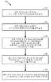
[0016] 도 4는 개시된 실시예들의 방법을 예시하는 흐름도이다.
[0017] 도 5는 개시된 실시예들의 다른 방법을 예시하는 흐름도이다.
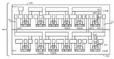
[0018] 도 6a는 도 1에 나타난 블록도의 더욱 상세한 구현이다.
[0019] 도 6b는 도 6a에 나타낸 회로에 대해 시간이 경과함에 따른 특정 전압 신호들의 경로를 예시하는 그래프이다.
[0020] 도 7은 모놀리식 3D 집적 회로로서 개시된 실시예들의 플립 플롭 구현의 단면도이다.BRIEF DESCRIPTION OF THE DRAWINGS [0012] The accompanying drawings are provided to illustrate the disclosed embodiments, and are provided by way of illustration only, and not limitation, of the embodiments.
[0013] FIG. 1 is a block diagram of the disclosed embodiments.
[0014] FIG. 2 is a table illustrating how various performance parameters may be improved by the disclosed embodiments.
[0015] FIG. 3 is a block diagram illustrating a two-tier example of the disclosed embodiments.
[0016] FIG. 4 is a flow chart illustrating the method of the disclosed embodiments.
[0017] FIG. 5 is a flow chart illustrating another method of the disclosed embodiments.
[0018] FIG. 6A is a more detailed implementation of the block diagram shown in FIG.
[0019] FIG. 6B is a graph illustrating the path of certain voltage signals over time for the circuit shown in FIG. 6A.
[0020] FIG. 7 is a cross-sectional view of a flip-flop implementation of embodiments disclosed as a monolithic 3D integrated circuit.
[0021] 본 발명의 양상들이, 본 발명의 특정 실시예들에 관련하여 이하의 설명 및 관련 도면들에 개시된다. 대안적인 실시예들이 본 발명의 범위로부터 벗어나지 않고 고안될 수 있다. 추가적으로, 본 발명의 잘-알려진 엘리먼트들은 본 발명의 관련 세부사항들을 모호하게 하지 않기 위해 상세하게 설명되지 않거나 또는 생략될 것이다.[0021] Aspects of the present invention are set forth in the following description and the associated drawings in connection with specific embodiments of the invention. Alternate embodiments may be devised without departing from the scope of the present invention. In addition, well-known elements of the present invention will not be described in detail or will be omitted so as not to obscure the relevant details of the present invention.
[0022] 단어 "예시적인"은 본원에서 "예, 예시, 또는 예증으로서 기능하는 것"을 의미하도록 사용된다. "예시적인"으로서 본원에 설명된 임의의 실시예는 반드시 다른 실시예들보다 바람직하거나 유리한 것으로서 해석되지는 않는다. 유사하게, 용어 "실시예들"은, 본 발명의 모든 실시예들이 논의된 특징, 이점 또는 동작의 모드를 포함하도록 요구하지 않는다.[0022] The word "exemplary" is used herein to mean "serving as an example, instance, or illustration. &Quot; Any embodiment described herein as "exemplary " is not necessarily to be construed as preferred or advantageous over other embodiments. Similarly, the term "embodiments " does not require that all embodiments of the invention include the features, advantages or modes of operation discussed.
[0023] 본원에 이용된 용어는, 오직 특정한 실시예들을 설명하기 위한 목적이고, 본 발명의 실시예들을 제한하도록 의도되지는 않는다. 본원에 이용된 바와 같이, 문맥이 그렇지 않은 것으로 명확하게 지시하지 않는 한, 단수 형태들은 복수 형태들도 또한 포함하는 것으로 의도된다. 용어들 "포함하다(comprises)", "포함하는(comprising)", "포함하다(includes)" 및/또는 "포함하는(including)"은, 본원에 이용되는 경우, 언급된 특징들, 정수들, 단계들, 동작들, 엘리먼트들, 및/또는 컴포넌트들의 존재를 특정하지만, 하나 또는 그 초과의 다른 특징들, 정수들, 단계들, 동작들, 엘리먼트들, 컴포넌트들, 및/또는 이들의 그룹들의 존재 또는 부가를 배제하는 것은 아니라는 것을 더 이해할 것이다.[0023] The terminology used herein is for the purpose of describing particular embodiments only, and is not intended to limit the embodiments of the invention. As used herein, the singular forms are intended to also include the plural forms unless the context clearly dictates otherwise. The terms " comprises, "" comprising," " includes, " and / or "including ", when used in this specification, Elements, steps, operations, elements, components, and / or components, but rather may involve one or more other features, integers, steps, operations, elements, Quot; is not intended to exclude the presence or addition of "
[0024] 게다가, 수많은 실시예들이, 예를 들어, 컴퓨팅 디바이스의 엘리먼트들에 의해 수행될 동작들의 시퀀스들과 관련하여 설명된다. 본원에 설명된 다양한 동작들은, 특정 회로들(예컨대, 주문형 집적회로들(ASIC들))에 의해, 하나 또는 그 초과의 프로세서들에 의해 실행되는 프로그램 명령들에 의해, 또는 이 둘의 조합에 의해 수행될 수 있다는 것을 인식할 것이다. 추가적으로, 본원에 설명된 동작들의 이러한 시퀀스는, 실행시에, 관련 프로세서로 하여금 본원에 설명된 기능을 수행하게 하는 대응 세트의 컴퓨터 명령들이 저장된 임의의 형태의 컴퓨터 판독가능 저장 매체 내에서 전체적으로 구현되는 것으로 고려될 수 있다. 따라서, 본원의 다양한 양상들은 다수의 상이한 형태들로 구현될 수 있고, 이 형태들 모두는 청구된 청구대상의 범위 내에 있는 것으로 고려된다. 또한, 본원에 설명된 실시예들 각각에 대해, 임의의 이러한 실시예들의 대응하는 형태는, 예를 들어, 설명된 동작을 수행하도록 "구성된 로직"으로서 본원에 설명될 수 있다.[0024] In addition, numerous embodiments are described in connection with, for example, sequences of operations to be performed by elements of a computing device. The various operations described herein may be performed by specific circuits (e.g., application specific integrated circuits (ASICs)), by program instructions executed by one or more processors, or by a combination of the two As will be appreciated by those skilled in the art. Additionally, such a sequence of operations described herein may be implemented entirely within any form of computer-readable storage medium having stored thereon a corresponding set of computer instructions for causing the associated processor to perform the functions described herein . ≪ / RTI > Accordingly, the various aspects of the present disclosure may be embodied in many different forms, all of which are considered to be within the scope of the claimed subject matter. Further, for each of the embodiments described herein, the corresponding form of any of these embodiments may be described herein as, for example, "configured logic" to perform the described operation.
[0025] 이제 관련 동작 환경의 개관을 참조하면, 정밀한 입도의 멀티-전력 도메인들은 현대의 SoC(즉, 시스템 온 칩) 설계들에서 성능 및 전력 관리를 위해 유리하다. 전력 도메인들 간의 동기화된 데이터 트랜스퍼는 로직 레벨 시프터를 요구한다. 또한, 크로스 도메인 레벨 시프터는 상이한 파워 서플라이들을 요구하며 이는 상당한 면적 페널티 및 도메인들 사이에서 크로싱하는 Vdd를 유도할 수 있다. 추가적으로, 이러한 전력 도메인들 간의 데이터 트랜스퍼는, 예를 들어, (1) 추가적인 레벨 시프터들에 대한 필요성이 상당한 면적 소모를 유도하는 것; (2) 크로스 도메인 레벨 시프터가 도메인들 사이에서 트립하는(tripping) Vdd를 위태롭게 하는 것; (3) 로컬 셀 레벨에서의 다수의 파워 서플라이 레일들도 또한 추가적인 면적 페널티를 유도하는 것을 포함하는 수많은 문제점들을 도입한다. 이러한 그리고 다른 문제들을 극복하기 위해, 개시된 실시예들은 콤팩트형 크로스 도메인 데이터 트랜스퍼 인터페이스로서 집적된 레벨 시프터를 갖는 저장 엘리먼트를 제안한다. 개시된 실시예들은 또한, 파워 서플라이들을 별개의 티어들로 분할하기 위해 3D 집적 회로 기술을 채용하며, 이에 의해 로컬 전력 레일 혼잡을 회피하고 추가로 크로스 토크를 최소화한다.[0025] Referring now to the overview of the relevant operating environment, fine-grained multi-power domains are advantageous for performance and power management in modern SoC (i.e., system-on-chip) designs. Synchronized data transfer between power domains requires a logic level shifter. In addition, cross domain level shifters require different power supplies, which can lead to significant area penalties and Vdd crossing between domains. In addition, data transfer between these power domains can be achieved, for example, by (1) the need for additional level shifters leading to significant area consumption; (2) jeopardizing the Vdd cross domain level shifter tripping between domains; (3) multiple power supply rails at the local cell level also introduce a number of problems including inducing additional area penalties. To overcome these and other problems, the disclosed embodiments propose a storage element having a level shifter integrated as a compact cross-domain data transfer interface. The disclosed embodiments also employ 3D integrated circuit technology to divide power supplies into separate tiers, thereby avoiding local power rail congestion and further minimizing crosstalk.
[0026] 이하에 더욱 상세하게 설명되고 예시된 바와 같이, 저장 엘리먼트는 모놀리식 3D 기술을 활용하는 상이한 전력 도메인들 간에 데이터를 트랜스퍼하는 레벨 시프터와 집적된 플립-플롭 회로로서 구현될 수 있다. 실시예들은 일반적으로 저전력 디지털 집적 회로들(IC) 및 3D IC 설계들의 분야이다. 더욱 구체적으로, 본 개시물은, 마스터-슬레이브 플립-플롭 내에 레벨 시프터를 통합시킴으로써 그리고 상이한 3D IC 티어들로 배열된 상이한 전력 도메인들에 걸친 데이터 경로를 제공함으로써 크로스 도메인 데이터 트랜스퍼 인터페이스의 회로 토폴로지 및 모놀리식 3D IC 구현을 설명하는데, 이는 (i) 플립-플롭(FF) 회로, (ii) FF 회로 내에 집적된 상이한 전력 도메인들 간의 레벨 시프터, (iii) 자기 유도 전력 붕괴 기법에 의한 기록 시간 딜레이들의 감소, (iv) 모놀리식 3D IC 기술을 이용하여 FF 파워 서플라이들을 상이한 티어들로 분할하는 것, 및 (v) 3D IC 티어들 사이에서의 크로스 전력 도메인 데이터 트랜스퍼들을 포함한다.[0026] As described and illustrated in greater detail below, the storage elements may be implemented as level shifters and integrated flip-flop circuits that transfer data between different power domains utilizing monolithic 3D technology. Embodiments are generally the field of low power digital integrated circuits (IC) and 3D IC designs. More particularly, the present disclosure provides circuit topology of a cross-domain data transfer interface by providing a data path across different power domains arranged by merging a level shifter in a master-slave flip-flop and with different 3D IC tiers and (Ii) a level shifter between different power domains integrated in the FF circuit, (iii) a level shifter between the write times by the magnetic induction power collapse technique, (Iv) dividing FF power supplies into different tiers using monolithic 3D IC technology, and (v) cross power domain data transfers between 3D IC tiers.
[0027] 이제 특정 개시된 실시예들을 참조하면, 도 1은 개시된 실시예들의 멀티-스테이지 회로(10)의 블록도이다. 나타낸 바와 같이, 멀티-스테이지 회로(10)는, 전력 도메인 A에서 동작하는 제 1 스테이지(26)와 함께 전력 도메인 B에서 동작하는 제 2 스테이지(40)를 포함한다. 전력 도메인 A는 전력 도메인 B와 상이하다. 로직 회로들은 데이터(예를 들어, D, msnd, msnd_n, Q)를 멀티-스테이지 회로(10) 내부로 그리고 외부로 통신한다. 클록 회로(80)는 로직(12, 14) 및 멀티-스테이지 회로(10)의 다양한 동기 컴포넌트들에 대한 클록 신호들(clk)을 제공한다. 데이터 경로들(16, 18, 20, 22, 24)은 다양한 회로들에 데이터 및 클록 신호들을 송신하기 위해 제공된다. 제 1 스테이지(26)는 전력 도메인 A에서 동작하는 저장 회로(28)를 포함한다. 제 2 스테이지(40)는, 전력 도메인 B에서 모두 동작하는, 절연 회로(42), 및 저장 기능(61), 레벨 시프트 기능(63) 및/또는 기록 강화 기능(65)을 갖춘 레벨 시프터 저장 회로(LSSC)(60)를 포함한다.[0027] Referring now to the specific disclosed embodiments, FIG. 1 is a block diagram of a
[0028] LSSC(60)는 레벨 시프팅 및 데이터 저장 기능들을 둘 다를 수행한다. 더욱 구체적으로, LSSC(60)는, 전력 도메인 A로부터 수신된 데이터를 전력 도메인 B로 시프트하고, 그리고 시프트된 전력 도메인 B 데이터를 LSSC(60)에 기록한다. 절연 회로(42)는 전력 도메인 A 전압 신호들과 전력 도메인 B 전압 신호들 사이의 절연을 제공하며 이에 의해 전력 도메인 A 신호들과 전력 도메인 B 신호들 사이의 크로스-토크에 대한 잠재성을 감소시킨다. 기록 강화 기능(65)은, 시프트된 전력 도메인 B 데이터를 LSSC(60)에 기록하는데 소요되는 시간만큼 야기된 딜레이(즉, 기록 시간 딜레이)를 감소시킴으로써 전반적인 효율을 개선시킨다.[0028] The
[0029] 개시된 실시예들, 및 특히 도 1에 나타낸 실시예의 하나의 중요한 양상은, 이들이 주요 회로 컴포넌트들(예를 들어, LSSC(60))의 크기가 감소되게 허용한다는 것이다. (도 6 및 도 7에 나타내고 그리고 이하 더욱 상세하게 설명된 바와 같이) 개시된 LSSC(60)가 MOSFET(Metal Oxide Semiconductor Field Effect Transistors)의 어레이로서 구현되는 경우, MOSFET들이 크기면에서 축소되기 때문에, 상당한 성능 이점들(예를 들어, 전력 및 면적 소모)이 달성될 수 있다.[0029] One important aspect of the disclosed embodiments, and in particular of the embodiment shown in FIG. 1, is that they allow the size of major circuit components (eg, LSSC 60) to be reduced. When the disclosed
[0030] 제 2 스테이지(40) 및 그의 컴포넌트들(42, 60)은, LSSC(60)로 하여금, 제 2 스테이지(40)가 알려진 레벨 시프터 저장 회로의 성능 페널티들(예를 들어, 면적 소모, 전력 소모, 기록 딜레이 등) 없이 구현될 수 있도록 충분히 작게 크기설정되게 허용한다. 이하 더욱 상세하게 설명된 바와 같이, 개시된 제 2 스테이지(40)는 종래의 슬레이브 스테이지의 풋프린트와 실질적으로 동일하게 가능한 작게 크기설정될 수 있다. 절연 회로(42)는 전력 도메인들(A, B) 사이의 크로스-토크를 제거하여 이에 의해 LSSC(60)의 크기가 알려진 레벨 시프터 저장 회로 구현들로부터 상당히 감소되게 허용한다. LSSC(60)의 크기를 감소시키는 것은 제 2 스테이지(40)의 전체 면적 및 전력 소모를 감소시킨다. LSSC(60)의 상대적으로 더 작은 면적 및 전력 소모로 인해, 데이터 기록 속도 및 효율이 개선된다. 데이터를 LSSC(60)에 더 쉽고 더 빠르게 기록하게 하기 위해 기록 강화 기능(65)에 추가적인 개선이 또한 제공된다. 절연 회로(42) 및 기록 강화 기능(65)은, 오직 소수의(a few) 액티브 엘리먼트들만을 갖는 단순한 설계들로서 구현될 수 있고 이에 의해 이들의 전력 및 면적 소모를 상대적으로 낮게 설정할 수 있다. 이에 따라, LSSC(60)의 크기를 감소시키는 것은 면적 및 전력 소모를 감소시키는 한편, 절연 회로(42) 및 기록 강화(65)는 효율을 개선시킨다(크로스-토크를 저하시키고, 기록 속도를 증가시킨다). 제 2 스테이지(40)에서의 비교적 단순한 절연 회로(42) 및 비교적 단순한 기록 강화 회로(65)의 추가로 인한 면적 및 전력 감소에 있어서의 약간의 증가는, LSSC(60)의 크기 및 풋프린트를 감소시키고 그리고 별도의 로직 레벨 시프터에 대한 필요성을 제거하는 것으로 인한 면적 및 전력 절감들에 의해 상쇄되는 것 이상이 된다.The
[0031] 따라서, 본원에 설명되고 예시된 회로 구성들을 활용하여, LSSC(60)의 면적 및 전력 소모가 상당히 감소될 수 있다는 점이 관찰될 수 있다. 예를 들어, 개시된 실시예들에 후속하여 6T(6개의 트랜지스터) 기록 강화 SRAM(WES) 구성(60c)(도 6a에 나타냄)으로서 LSSC(60)가 구현될 때, 6T SRAM의 풋프린트 면적은, 크로스 커플 인버터 래치의 크기를 축소함으로써, 제시된 기술 노드에서의 통상적 비트셀 풋프린트보다 더 작거나 또는 80%일 수 있다. 이는, (상보적 입력 msnd_n이 로우에 있으면서) 입력 신호(msnd)가 하이에 있을 때 내부 노드 bit_n을 접지로 풀링하고(pull) 그리고 래치 셀이 내부 노드 비트를 하이(전력 도메인 B의 Vdd)로 충전하게 강제하는 차동 n-채널 MOSFET 입력 트랜지스터들(44, 46)에 의해 제안된 추가적인 풀 다운 세기로 달성되며, 이에 따라 LSSC(60c) 내부의 트랜지스터들이 비례해서 크기가 축소되어 기록 전력 및 효율이 개선될 수 있다.[0031] Thus, it can be observed that utilizing the circuit configurations described and illustrated herein, the area and power consumption of the
[0032] 도 2는, 도 1에 나타낸 제 2 스테이지 회로(40)를 이용하여 달성될 수 있는 전력 소모, 면적 소모 및 IC 딜레이 이점들의 일례를 예시하는 표이다. 도 2는, 종래의 제 2 스테이지 레벨 시프터 및 저장 회로의 전력 소모, 면적 소모 및 IC 딜레이를 도 1에 나타낸 제 2 스테이지 회로(40)와 비교한다. 예시의 목적들로, 종래 설계의 저장 회로는 플립-플롭(FF) 회로이다. 또한, 예시 및 비교의 목적들로, 종래의 레벨 시프터 + FF 설계의 전반적인 제 2 스테이지 전력 소모에 대한 기여는 임의적으로 1.00로 설정되며, 종래의 레벨 시프터 + FF 설계의 전반적인 면적 소모에 대한 기여는 임의적으로 1.00로 설정되며, IC 딜레이에 대한 기여도 임의적으로 1.00로 설정된다. 제 2 스테이지 레벨 시프터 및 저장 엘리먼트들(61, 63)은, 이들의 전력 소모가 예를 들어 0.50이고 이들의 면적 소모가 예를 들어 0.50이 될 때까지, 계속적으로 감소된다. 절연 회로(42)는, 이 절연 회로가 상당한 과잉 전력 소모를 유도하지 않고 자신의 면적 소모가 예를 들어 0.125가 되도록, 소수의(few) 액티브 엘리먼트들을 갖는 단순한 회로로서 구현된다. 기록 강화(65)는, 이 기록 강화가 상당한 과잉 전력 소모를 유도하지 않고 자신의 면적 소모가 예를 들어 0.125가 되도록, 소수의 액티브 엘리먼트들을 갖는 단순한 회로로서 구현된다. 후술되는 더욱 상세한 실시예들에서, 기록 강화는 레벨 시프터에 의해 제공되어, 이러한 실시예들의 경우, 면적 소모에 대한 기록 강화의 기여는 실질적으로 0일 것이다. 추가적으로, 기록 강화(65)는, 제 2 스테이지 저장(61)에 대한 기록 시간이 예를 들어 0.50이 되도록, 기록 딜레이를 감소시킨다. 이에 따라, 조합된 제 2 스테이지 회로(40)는 0.50의 전체 전력 소모, 0.75의 전체 면적 소모, 및 0.50의 전체 기록 시간 딜레이를 갖는다. 이에 따라, 개시된 실시예에 따라 조합된 제 2 스테이지 회로(40)는 전력 및 면적 소모 절감과 함께 앞서 설명된 개선된 기록 효율을 제공한다. 앞서-설명된 실시예들은, 레벨 시프팅 및 저장 회로로 하여금 멀티-스테이지 회로(10)의 전체 회로 면적의 대략적으로/약 70%미만을 포함하도록 허용하고, 전체 레벨 시프터 집적 마스터-슬레이브 플립-플롭 설계는 종래의 FF + 시프터 설계의 전체 풋프린트의 대략적으로/약 50% 미만을 포함한다. 멀티-스테이지 회로의 전체 회로 면적이 각각의 스테이지의 회로 면적들의 합계를 나타낸다는 점을 주목해야 한다.[0032] FIG. 2 is a table illustrating an example of power consumption, area consumption, and IC delay benefits that may be achieved using the
[0033] 도 3은, 전력 도메인 A에서 동작하는 제 1 티어(102)와 함께 전력 도메인 B에서 동작하는 제 2 티어(104)를 갖는 멀티-티어 회로(100)에서 구현된 멀티-스테이지 회로(10a)를 예시한다. 멀티-티어 회로(10a)의 제 1 스테이지(26a)는 제 1 티어(102) 상에 있고, 멀티-티어 회로(10a)의 제 2 스테이지(40a)는 제 2 티어(104) 상에 있다. 제 2 스테이지(40a)는 도 1에 나타낸 제 2 스테이지 회로(42, 65)를 포함하거나 또는 포함하지 않을 수 있다. 각각의 전력 도메인(A 및 B)은 통상적으로 그들 자신의 전력 레일(106, 108)을 요구한다. 멀티-티어 구성(100) 상에서 구현된 멀티-스테이지 회로(10a)는 전력 레일(106)이 제 1 티어(102) 상에서 구현되도록 허용하고 그리고 전력 레일(108)이 제 2 티어(104) 상에서 구현되도록 허용한다. 이에 따라, 퍼(per)/티어 전력 레일 혼잡은 멀티-스테이지 회로(10a)의 단일 티어 구현을 통해 감소된다.[0033] Figure 3 illustrates a multi-stage circuit 100 implemented in a multi-tier circuit 100 having a
[0034] 도 4 및 도 5는 개시된 실시예들의 설계 기법들을 추가로 예시하는 프로세스 흐름도들이다. 도 4는 도 1에 나타낸 회로 토폴로지에 대한 설계 기법(200)을 추가로 예시하고, 도 5는 도 3에 나타낸 회로 토폴로지에 대한 설계 기법(300)을 추가로 예시한다. 도 4 및 도 5에 나타낸 설계 단계들의 시퀀스는 오직 예시의 목적들을 위한 것이며, 실제로, 이 단계들은 나타낸 순서로 수행될 수 있거나 또는 수행되지 않을 수도 있다. 예를 들어, LSSC(60)의 크기를 감소시키는 것은 설계 프로세스에서 다른 단계들과 함께 그 이전에, 그 후에 또는 동시에 수행될 수 있는 반복적이고 연속적인 평가이다. 도 4에 나타낸 바와 같이, 단계(202)에서 설계 기법(200)은 전력 도메인 A에서 동작하는 제 1 스테이지 저장 회로(FSSC)(26, 28)를 선택 및/또는 설계한다. 단계(204)는 전력 도메인 B에서 동작하는 제 2 스테이지 회로(SSC)(40)를 설계 및/또는 선택한다. 단계(206)는 저장 기능(61) 및 레벨 시프트 기능(63)을 SSC(40)에 통합하고, 여기서 레벨 시프트(63)는 전력 도메인 A로부터 수신된 데이터를 전력 도메인 B로 시프트하고 그 데이터를 저장소(61)에 기록한다. 단계(208)는 LSSC(60)의 크기 및 전력 소모를 감소시킨다. 단계(210)는 절연 회로(42)를 SSC(40)에 통합하고, 여기서 절연 회로(42)는 전력 도메인 A에서 동작하는 FSSC(26, 28)와 전력 도메인 B에서 동작하는 SSC(40) 사이에서의 크로스 토크를 제한한다. 단계(212)는 기록 강화(WE)(65)를 SSC(40)에 통합하고, 여기서 WE(65)는 LSSC(60)에 데이터를 기록하는 효율을 개선시킨다. 단계(214)는, 필요한 경우, 추가로, LSSC(60)의 크기 및/또는 전력 소모를 감소시키고 그리고/또는 설계를 조절한다. 단계(216)는, 필요한 경우, 절연 회로(42)의 설계, 크기 및/또는 전력 소모를 조절한다. 단계(220)는, SSC(40)의 풋프린트, 전력 소모 및/또는 기록 효율이 최적화되었는지 여부를 평가한다. 만약 아니라면, 설계 기법(200)은 단계(214)로 돌아가고, 필요한 경우, 추가로, LSSC(60)의 크기 및/또는 전력 소모를 감소시키고 그리고/또는 설계를 조절한다. 단계(220)에서의 질의에 대한 답변이 예이면, 설계 기법(200)은 단계(222)로 계속하고 FSSC(26) 및 그의 연관된 제 1 전력 레일 A(106)을 멀티-티어 구성(100)의 제 1 티어(102) 상에 위치시킨다. 단계(224)는 SSC(40) 및 그의 연관된 제 2 전력 레일(108)을 멀티-티어 구성(100)의 제 2 티어(104) 상에 위치시킨다.[0034] Figures 4 and 5 are process flow diagrams that further illustrate the design techniques of the disclosed embodiments. FIG. 4 further illustrates a
[0035] 도 5는 도 3에 나타낸 회로 토폴로지(100)에 대한 예시적인 설계 기법(300)을 예시한다. 도 5에 나타낸 바와 같이, 단계(302)는 전력 도메인 A에서 동작하는 FSC(26a)를 선택 및/또는 설계한다. 단계(304)는 전력 도메인 B에서 동작하는 SSC(40a)를 선택 및/또는 설계한다. 단계(306)는 LSSC(60a)를 SSC(40a)에 통합하고, 여기서 LSSC(60a)는 전력 도메인 A에서 수신된 데이터를 전력 도메인 B로 시프트하고 그리고 시프트된 데이터를 LSSC(60a)에 기록한다. 단계(308)는 FSC(26a) 및 그의 연관된 제 1 스테이지 전력 레일(106)을 멀티-티어 구성(100)의 제 1 티어(102) 상에 위치시킨다. 최종적으로, 단계(310)는 SSC(40a) 및 그의 연관된 제 2 스테이지 전력 레일(108)을 멀티-티어 구성(100)의 제 2 티어(104) 상에 위치시킨다.[0035] FIG. 5 illustrates an
[0036] 도 6a는 도 1에 나타낸 멀티-스테이지 회로(10)의 더욱 상세화된 구현인 멀티-스테이지 회로(10c)를 예시한다. 멀티-스테이지 회로(10c)는 마스터-슬레이브 플립-플롭 구성으로 나타나며, 여기서 제 1 스테이지 저장 회로(28c)는 전력 도메인 A에서 동작하는 마스터 플립-플롭 회로로서 구현되고, 제 2 스테이지 저장 회로(40c)는 모두 전력 도메인 B에서 동작하는, 슬레이브 플립-플롭 구성(61c), 절연 회로 구성(42c) 및 기록 강화 회로 구성(65c)으로서 구현된다. 클록 회로(80c)는 멀티-스테이지 회로(10c)의 다양한 동기화 컴포넌트들에 대한 클록 신호들(clk)을 제공한다.[0036] FIG. 6A illustrates a
[0037] 마스터 플립-플롭 회로(28c)는, 나타낸 바와 같이 구성된, 제 1 인버터(30), 제 2 인버터(34), 및 제 3 인버터(36)를 포함한다. 슬레이브 저장 회로(40c)는, 마스터 플립 플롭(28a)으로부터 데이터(msnd)를 동기식으로 수신하고, 전력 도메인 A으로부터 수신된 데이터를 전력 도메인 B로 시프트하고, 그리고 데이터를 저장 회로(61c)에 기록한다. 절연 회로(42c)는 제 1 입력 n-채널 MOSFET (metal oxide semiconductor field effect transistor)(44), 제 2 차동 입력 n-채널 MOSFET(46), 및 출력 Q 상태를 정정하기 위해 데이터를 변환하고 나타낸 바와 같이 구성된 출력 Q에 절연을 제공하는 인버터(48)를 포함한다. 기록 강화(65c)는 나타낸 바와 같이 구성된 제 1 p-채널 MOSFET(52)로서 구현된다. 레벨 시프터 저장 회로(60a)는, 나타낸 바와 같이 구성된, 제 2 p-채널 MOSFET(62), 제 3 p-채널 MOSFET(64), 제 3 n-채널 MOSFET(66), 제 4 n-채널 MOSFET(68), 제 5 n-채널 MOSFET(70) 및 제 6 n-채널 MOSFET(72)을 포함하는 6T SRAM 구성으로서 구현된다. 클록 회로(80a)는 나타낸 바와 같이 구성된 압전 결정체 또는 패스 게이트(32), 제 4 인버터(74) 및 제 5 인버터(76)로서 구현된다.The master flip-
[0038] 이제, 멀티-스테이지 회로(10c)의 동작이 도 6a 및 도 6b에 나타낸 전압/시간 그래프들과 관련하여 설명될 것이다. 동작시에, 입력 데이터 D는 전력 도메인 A에서 마스터 플립-플롭(28c)에 동기식으로 저장된다. 전력 도메인 A에서의 마스터 플립-플롭(28c)은 FF 셋업 & 홀드 시간들을 결정한다. 데이터 D(0 또는 1)는 D를 D_n으로 인버팅하는 인버터(30)에 도달하고 그리고 입력에 대한 전압 절연으로서 기능한다. 클록 신호가 하이(1)로 진행할 때, 패스 게이트(32)는 턴 온 되고, 데이터 D_n은 데이터 D_n을 다시 D로 변환하는 인버터(34)로 전달되어 "msnd"에서의 출력 상태 D가 슬레이브 스테이지의 n-채널 MOSFET(44)의 게이트에 제시된다. 상보적 D_n은 또한 msnd_n에서 n-채널 MOSFET(46)의 게이트에 제시된다. 이제, 클록 신호가 로우(0)로 진행하면, 패스 게이트(32)는 턴 오프된다. 동시에, 인버터(36)는 복합 클록 신호(conjugated clock signal)에 의해 인에이블되어, 백-투-백 인버터 래치 루프를 폐쇄하고 저장 기능이 발생하도록 인에이블한다. 데이터 D는 이제, 다음 클록 사이클까지 인버터(30)에 제시되는 어떠한 이후의 데이터 상태(0 또는 1)에도 상관없이, 마스터 스테이지에 저장된다. 이때, 모든 동작들은 전력 도메인 A에서 수행되고, 이에 따라 저장된 그리고 출력된 데이터는 모두 전력 도메인 A 전압 레벨에 의해 정의된다.[0038] Now, the operation of the
[0039] msnd 데이터는 제 1 n-채널 MOSFET(44)에 제공되고 상보적 msnd_n은 제 2 n-채널 MOSFET(46)에 제공된다. msnd 데이터가 패스 게이트 트랜지스터(70)에 전달되는 종래의 접근방식들과는 다르게, n-채널 MOSFET들(44, 46)은, (1) 도메인 A와 도메인 B 사이에서 파워 서플라이들을 절연하고; (2) 슬레이브 스테이지 데이터 입력 포트들로서 기능하며; (3) 개선된 기록 성능을 가지고, 저장 유닛(61c)이 크기가 축소되게 허용하는 하이에 입력 신호가 있을 때 여분의 풀 다운 세기를 제공하도록 작용한다.[0039] The msnd data is provided to the first n-
[0040] msnd 데이터 D가 전력 도메인 A의 Vdd 레벨에서 하이(1)이면, n-채널 MOSFET(44)가 턴 온 하면서 액세스 트랜지스터(70)가 클록 신호(clk)에 의해 (선택되어) 턴 온 한다. 이러한 조합된 동작은 도 6a에 나타낸 바와 같이 "bit_n"를 로우(0)로 풀링하도록 기능한다. bit_n이 로우 쪽으로 이동함에 따라, Vdd-Vbit_n이 p-채널 MOSFET(64)의 임계 전압보다 더 클 때 p-채널 MOSFET(64)을 턴 온시키고, Vbit_n이 n-채널 MOSFET(68)의 임계 전압보다 더 낮을 때 n-채널 MOSFET(68)를 셧 오프(shut off)시킨다. 결과적으로, 노드 "bit"는 파워 서플라이 Vdd에 의해 충전되고, "bit" 레벨(전압)이 Vdd 쪽으로 계속 이동함에 따라, 결국 p-채널 MOSFET(62)을 셧 오프시키고 n-채널 MOSFET(66)을 턴 온시키며, 이에 따라 포지티브 피드백 래치가 인에이블되어, "bit_n"을 접지로 빠르게 풀링하면서 "bit"를 Vdd로 푸쉬한다. 이에 따라, 데이터 D에 의해 정의된 새로운 상태가 저장 셀(61c)에 레코딩(기록)된다. 인버터(48)는 이제 로우(0)에서의 "bit_n"를 하이(1)에서의 Q로 인버팅하도록 기능한다. 이 동작의 이러한 부분이 전력 도메인 B에 있기 때문에, 하이 출력은 또한 정확한 Vdd 레벨의 도메인 B를 갖는다. 이때, 전력 도메인 A 전압 레벨에서의 입력 하이(D=1)는 전력 도메인 B 전압 레벨에서의 출력 하이(Q=1)로 성공적으로 트랜스퍼된다. 유사하게, msnd 데이터 D가 로우(0)이면, msnd_n는 하이(1)에 있다. n-채널 트랜지스터(46) 및 p-채널 트랜지스터(62)가 턴 온되어, bit_n가 Vdd에 의해 충전되도록 강제되고 그리고 데이터가 저장 셀(61c)에 기록되며, 결국 하이 bit_n 신호(1)가 정확한 로우 출력 데이터(Q=0)로 변환된다.When the msnd data D is high (1) at the Vdd level of the power domain A, the
[0041] 이에 따라, 멀티-스테이지 회로(10c)는 입력 데이터 D를 2개의 상이한 전력 도메인들에 걸친 정확한 출력 Q 상태로 트랜스퍼한다. 기록 효율의 추가적인 강화는, 저장 회로(61c)와 파워 서플라이를 연결하는 언제나(all-time) 온(on) 상태의 p-채널 MOSFET(52)인 자기 유도 전력 붕괴(SIPC) 회로를 이용하여 제공된다. 앞서 설명된 바와 같이, 저장 회로(61c)는 저장 상태를 설정하는 래치 기능을 제공하는데, 이 기능은 예를 들어, "bit_n"을 하이(1)로부터 로우(0)로 스위칭하고 "bit"를 로우(0)로부터 하이(1)로 스위칭한다. 스위칭 속도는, "bit_n" 전압이 얼마나 빨리 풀 다운될 수 있는지에 의해 주로 결정된다. 그러나, "bit" 전압이 Vdd-Vbit_n까지 충전되지 않은 초기 트랜션트(transient) 동안, 트랜지스터(62)는 여전히 온(on)이며 이는 "bit_n"를 계속해서 충전할 것이다. "bit_n"의 전압은 p-채널 트랜지스터(62)에 의한 풀-업 그리고 n-채널 트랜지스터들(44 및 66)에 의한 풀-다운의 경쟁적인 힘들에 의해 결정되지 않는다. SIPC는, 트랜지스터들(62 및 64)을 로딩하는 노드 S에서 내부 바이어싱 전압을 억제함으로써 이러한 트랜션트 문제를 극복한다. 트랜션트 기간에, 전류는 언제나 온(on)인 p채널 트랜지스터(52)를 통해서 전도하고 있다. 트랜지스터는, 이 트랜지스터가 적절한 전압 강하, 예를 들어, 도 6b에 나타낸 바와 같이 저장 셀이 래치하기 시작할 때 Vdd로 복귀하지만 트랜션트 시에 Vdd 서플라이로부터 20-30% 전압 강하를 전달하게 크기설정된다. 이러한 강화만으로도 clk-대-Q 딜레이에 대해 대략적으로 20% 개선이 달성된다.[0041] Thus, the
[0042] 도 7은, 전력 도메인 A에서 동작하는 제 1 티어(102d) 및 전력 도메인 B에서 동작하는 제 2 티어(104d)를 갖는 모놀리식 3D 집적 회로(100d)에서 구현되는 도 6a의 마스터-슬레이브 FF 회로(10c)의 일부의 예시적인 단면도를 예시한다. 단면은, 모든 상호연결부들을 나타내도록 의도되지 않은 구현예이다. 예시된 설계는, 멀티 전력 도메인 데이터 트랜스퍼 인터페이스를 실현하기 위해 각각의 티어 상에 오직 단일 전력 레일(미도시)을 필요로 하는 모놀리식 3D 집적 회로들에서 활용될 수 있다. 이는, 레이아웃 면적을 크게 감소시킬 수 있고 물리적 설계 복잡도를 크게 감소시킬 수 있다. 마스터 스테이지 및 슬레이브 레벨 시프터 스테이지는, 유사한 전체 트랜지스터 폭을 갖고, 더 나은 풋프린트 효율을 위해 2개의 티어들(102, 104)로 균등하게 분할된다. 도 7은, 설계의 마스터 및 슬레이브 스테이지들이 모놀리식 티어-간 비아들에 의해 연결되는 일례를 도시한다. MIV1(112)은, msnd_n에 대한 크로스 티어 데이터 경로를 제공하는, 도 6a의 티어 0의 마스터 스테이지의 패스 게이트 트랜지스터(30)의 드레인(D)으로부터 티어 1의 슬레이브 스테이지(미도시)의 입력 트랜지스터(46)로의 연결을 예시한다. MIV2(116)는, msnd에 대한 크로스 티어 데이터 경로를 제공하는, 도 6a의 티어 0의 인버터(34)의 출력으로부터 티어 1의 슬레이브 스테이지(미도시)의 입력 트랜지스터(44)로의 연결을 예시한다. MIV3(114)은 도 6a의 클록 생성기 블록(80)에 의해 공급된 클록에 대한 링크일 수 있다. 각각의 티어에서 NMOS 및 PMOS 및 콘택, M1, M2, V1은 마스터 및 슬레이브 스테이지들의 대응 회로의 회로들을 연결하는 컴포넌트들이다. 일 실시예는 도 7에 나타낸 바와 같이 연결을 위해 금속의 2개의 층들을 이용한다.[0042] FIG. 7 illustrates the master of FIG. 6a implemented in a monolithic 3D integrated
[0043] 따라서, 개시된 실시예들은 전력 도메인들에 걸쳐 효율적으로 동작하는, 매우 콤팩트하고, 매우 신뢰가능한 저전력 컴포넌트들 및 회로들임을 알 수 있다. 개시된 실시예들은 딜레이 개선 및 에너지 절감 둘 다를 추가로 제공한다. 일 실시예에서, 알려진 접근방식에 비해 40%의 클록-Q 딜레이 감소 및 50% 이상의 전력 절감이 달성된다. 에너지-딜레이 곱(energy-delay product)은 55%만큼 감소된다. 개선된 성능 파라미터들 및 감소된 컴포넌트 풋프린트는 설계 강건성을 보장하고, 3D 집적 회로 구현 기법들은 미래의 멀티-전력 도메인 3D IC 시스템들에서 크로스 티어, 크로스 도메인 동기화 데이터 트랜스퍼에 있어서 필수적이다. 게다가, 레벨 시프터 저장소를 크기 축소시키는 것은 또한 기록 속도 및 효율에 도움을 준다. 이에 따라, 전체 기록 강화 기법들은 2개의 주요 컴포넌트들을 포함한다: (1) 자기 유도 전력 붕괴 기법(예를 들어, p-채널 MOSFET 헤더 셀), 이에 의해 기록 전력 및 시간이 감소됨; (2) 레벨 시프터 저장 래치 쌍들의 풋프린트가 감소되고, 이에 의해 충전 커패시턴스를 감소시키는데, 이는 (절연을 위한) 차동 입력 트랜지스터들이 기록 동작 동안 여분의 풀 다운 세기를 제공하기 때문에 가능하다.[0043] Thus, it will be appreciated that the disclosed embodiments are very compact, highly reliable low power components and circuits that operate efficiently across power domains. The disclosed embodiments additionally provide both delay improvement and energy saving. In one embodiment, a 40% clock-Q delay reduction and a 50% power savings over the known approach are achieved. The energy-delay product is reduced by 55%. Improved performance parameters and reduced component footprint ensure design robustness and 3D integrated circuit implementation techniques are essential for cross-tier, cross-domain synchronized data transfer in future multi-power domain 3D IC systems. In addition, reducing the size of the level shifter storage also contributes to recording speed and efficiency. Thus, the overall write enforcement techniques include two major components: (1) a magnetic induction power collapse technique (e.g., a p-channel MOSFET header cell), thereby reducing write power and time; (2) The footprint of the level shifter storage latch pairs is reduced, thereby reducing charge capacitance, which is possible because differential input transistors (for isolation) provide extra pull down strength during a write operation.
[0044] 이전 개시물 및 예시들이 본 발명의 실시예들을 나타내지만, 첨부된 청구항들에 의해 정의되는 본 발명의 범위로부터 벗어나지 않고 다양한 변화들 및 변형들이 본원에서 행해질 수 있다는 것에 주목해야 한다. 예를 들어, 본원에 설명된 본 발명의 실시예들에 따른 방법 청구항들의 기능들, 단계들 및/또는 동작들은 임의의 특정한 순서로 수행될 필요는 없다. 게다가, 본 발명의 엘리먼트들은 단수표현으로 설명되거나 또는 청구될 수 있지만, 단수표현으로의 제한이 명확하게 언급되지 않는 한 복수표현도 고려된다.[0044] It should be noted that while the foregoing disclosure and examples illustrate embodiments of the invention, various changes and modifications can be made herein without departing from the scope of the invention as defined by the appended claims. For example, the functions, steps and / or operations of method claims in accordance with the embodiments of the invention described herein need not be performed in any particular order. In addition, elements of the invention may be described or claimed in the singular, but multiple representations are contemplated unless limitation to the singular is explicitly stated.
[0045] 본원에 개시된 실시예들과 관련하여 설명되는 다양한 예시적인 논리 블록들, 모듈들, 회로들 및 알고리즘 단계들은 전자 하드웨어, 컴퓨터 소프트웨어, 또는 이들 둘의 조합들로서 구현될 수 있다는 것이 당업자들에게 인식될 것이다. 하드웨어와 소프트웨어의 상호 교환 가능성을 명료하게 설명하기 위해, 다양한 예시적인 컴포넌트들, 블록들, 모듈들, 회로들 및 단계들이 그들의 기능과 관련하여 앞서 일반적으로 설명되어 있다. 이러한 기능이 하드웨어로 구현되는지 또는 소프트웨어로 구현되는지는 특정 애플리케이션 및 전체 시스템에 부과되는 설계 제약들에 의존한다. 당업자들은 설명된 기능을 각각의 특정한 애플리케이션에 대하여 다양한 방식들로 구현할 수 있으나, 이러한 구현 결정들은 본 발명의 범위를 벗어나게 하는 것으로 해석되어서는 안된다.It should be understood by those skilled in the art that the various illustrative logical blocks, modules, circuits, and algorithm steps described in connection with the embodiments disclosed herein may be implemented as electronic hardware, computer software, Will be recognized. To clearly illustrate the interchangeability of hardware and software, various illustrative components, blocks, modules, circuits, and steps have been generally described above in terms of their functionality. Whether such functionality is implemented as hardware or software depends upon the particular application and design constraints imposed on the overall system. Skilled artisans may implement the described functionality in varying ways for each particular application, but such implementation decisions should not be interpreted as causing a departure from the scope of the present invention.
[0046] 본원에 개시된 실시예들과 관련하여 설명된 방법들, 시퀀스들 및/또는 알고리즘들은 직접 하드웨어로 구현되거나, 프로세서에 의해 실행되는 소프트웨어 모듈로 구현되거나, 또는 이 둘의 조합으로 구현될 수 있다. 소프트웨어 모듈은 RAM 메모리, 플래시 메모리, ROM 메모리, EPROM 메모리, EEPROM 메모리, 레지스터들, 하드 디스크, 탈착식 디스크, CD-ROM, 또는 당업계에 공지된 임의의 다른 형태의 저장 매체에 상주할 수 있다. 예시적인 저장 매체는, 프로세서가 저장 매체로부터 정보를 판독하고 저장 매체에 정보를 기록할 수 있도록, 프로세서에 커플링된다. 대안적으로, 저장 매체는 프로세서에 통합될 수 있다. 이에 따라, 본 발명의 실시예는 개시된 그리고 청구된 실시예를 수행하기 위한 방법을 채용하는 컴퓨터 판독가능 매체를 포함할 수 있다. 이에 따라, 본 발명은 예시된 예시들로 제한되지 않으며, 본원에 설명된 기능을 수행하기 위한 임의의 수단은 본 발명의 실시예에 포함된다.[0046] The methods, sequences and / or algorithms described in connection with the embodiments disclosed herein may be embodied directly in hardware, in a software module executed by a processor, or in a combination of the two have. The software module may reside in RAM memory, flash memory, ROM memory, EPROM memory, EEPROM memory, registers, a hard disk, a removable disk, a CD-ROM, or any other form of storage medium known in the art. An exemplary storage medium is coupled to the processor such that the processor can read information from, and write information to, the storage medium. Alternatively, the storage medium may be integrated into the processor. Accordingly, embodiments of the invention may include computer readable media employing methods for performing the disclosed and claimed embodiments. Accordingly, the invention is not limited to the illustrated examples, and any means for performing the functions described herein are included in embodiments of the present invention.
Claims (40)
Translated fromKorean전력 도메인 A에서 동작하는 제 1 스테이지 및 전력 도메인 B에서 동작하는 제 2 스테이지를 포함하는 멀티-스테이지 회로 구성;
제 1 티어; 및
제 2 티어를 포함하고,
상기 제 1 스테이지는 데이터를 저장하기 위한 제 1 수단을 포함하고;
상기 제 2 스테이지는 데이터를 레벨 시프트 및 저장하기 위한 수단을 포함하며;
상기 제 1 티어는 상기 제 1 스테이지 및 상기 제 1 스테이지에 전력을 제공하기 위한 수단을 포함하고; 그리고
상기 제 2 티어는 상기 제 2 스테이지 및 상기 제 2 스테이지에 전력을 제공하기 위한 수단을 포함하는,
멀티-티어 집적 회로.A multi-tier integrated circuit comprising:
A multi-stage circuit configuration comprising a first stage operating in power domain A and a second stage operating in power domain B;
A first tier; And
A second tier,
The first stage comprising first means for storing data;
The second stage comprising means for level shifting and storing data;
The first tier including means for providing power to the first stage and the first stage; And
And the second tier comprises means for providing power to the second stage and the second stage.
Multi-tier integrated circuit.
상기 제 1 스테이지에 전력을 제공하기 위한 상기 수단은 제 1 전력 레일을 포함하고; 그리고
상기 제 2 스테이지에 전력을 제공하기 위한 상기 수단은 제 2 전력 레일을 포함하는,
멀티-티어 집적 회로.The method according to claim 1,
Wherein the means for providing power to the first stage comprises a first power rail; And
Wherein the means for providing power to the second stage comprises a second power rail,
Multi-tier integrated circuit.
상기 제 1 스테이지와 상기 제 2 스테이지 사이에서 데이터를 전송(transporting)하기 위한 수단을 더 포함하는,
멀티-티어 집적 회로.3. The method of claim 2,
Further comprising means for transporting data between the first stage and the second stage,
Multi-tier integrated circuit.
상기 데이터를 전송하기 위한 수단은 비아들의 네트워크를 포함하는,
멀티-티어 집적 회로.The method of claim 3,
Wherein the means for transmitting the data comprises a network of vias,
Multi-tier integrated circuit.
상기 비아들의 네트워크는 모놀리식 티어-간(monolithic inter-tier) 비아들을 포함하는,
멀티-티어 집적 회로.5. The method of claim 4,
The network of vias may include monolithic inter-tier vias,
Multi-tier integrated circuit.
전력 도메인 A에서 동작하는 제 1 스테이지;
전력 도메인 B에서 동작하는 제 2 스테이지; 및
제 1 티어 및 제 2 티어를 포함하고,
상기 제 1 스테이지는 데이터를 저장하기 위한 제 1 수단을 포함하고;
상기 제 2 스테이지는 전력 도메인 A에서 동작하는 상기 제 1 스테이지를 전력 도메인 B에서 동작하는 상기 제 2 스테이지로부터 절연시키기 위한 수단을 포함하고;
상기 제 2 스테이지는 전력 도메인 B에서 데이터를 레벨 시프트 및 저장하기 위한 수단을 더 포함하고,
상기 레벨 시프트 및 저장하기 위한 수단은, 상기 레벨 시프트 및 저장하기 위한 수단에 데이터를 기록하는 것을 강화하기 위한 수단을 더 포함하고,
상기 제 1 티어는 상기 제 1 스테이지 및 상기 제 1 스테이지에 전력을 제공하기 위한 수단을 포함하고; 그리고
상기 제 2 티어는 상기 제 2 스테이지 및 상기 제 2 스테이지에 전력을 제공하기 위한 수단을 포함하는,
멀티-스테이지 회로 구성물.14. A multi-stage circuit arrangement comprising:
A first stage operating in power domain A;
A second stage operating in power domain B; And
A first tier and a second tier,
The first stage comprising first means for storing data;
The second stage comprising means for isolating the first stage operating in power domain A from the second stage operating in power domain B;
The second stage further comprises means for level shifting and storing data in power domain B,
Wherein the means for level shifting and storing further comprises means for enhancing the writing of data to the means for level shifting and storing,
The first tier including means for providing power to the first stage and the first stage; And
And the second tier comprises means for providing power to the second stage and the second stage.
A multi-stage circuit arrangement.
상기 제 1 스테이지에 전력을 제공하기 위한 상기 수단은 제 1 전력 레일을 포함하고; 그리고
상기 제 2 스테이지에 전력을 제공하기 위한 상기 수단은 제 2 전력 레일을 포함하는,
멀티-스테이지 회로 구성물.The method according to claim 6,
Wherein the means for providing power to the first stage comprises a first power rail; And
Wherein the means for providing power to the second stage comprises a second power rail,
A multi-stage circuit arrangement.
상기 제 1 스테이지와 상기 제 2 스테이지 사이에서 데이터를 전송하기 위한 수단을 더 포함하는,
멀티-스테이지 회로 구성물.8. The method of claim 7,
Further comprising means for transferring data between the first stage and the second stage,
A multi-stage circuit arrangement.
상기 데이터를 전송하기 위한 수단은 비아들의 네트워크를 포함하는,
멀티-스테이지 회로 구성물.9. The method of claim 8,
Wherein the means for transmitting the data comprises a network of vias,
A multi-stage circuit arrangement.
상기 비아들의 네트워크는 모놀리식 티어-간 비아들을 포함하는,
멀티-스테이지 회로 구성물.10. The method of claim 9,
Wherein the network of vias includes monolithic tier-
A multi-stage circuit arrangement.
상기 데이터를 저장하기 위한 수단은 마스터 플립-플롭을 포함하고;
상기 데이터를 레벨 시프트 및 저장하기 위한 수단은 슬레이브 플립-플롭 및 레벨 시프터 회로를 포함하는,
멀티-스테이지 회로 구성물.The method according to claim 6,
Wherein the means for storing the data comprises a master flip-flop;
Wherein the means for level shifting and storing the data comprises a slave flip-flop and a level shifter circuit,
A multi-stage circuit arrangement.
상기 슬레이브 플립-플롭 및 레벨 시프터는 복수의 SRAM 트랜지스터들을 포함하는,
멀티-스테이지 회로 구성물.12. The method of claim 11,
Wherein the slave flip-flop and the level shifter comprise a plurality of SRAM transistors,
A multi-stage circuit arrangement.
상기 데이터를 레벨 시프트 및 저장하기 위한 수단은, 상기 멀티-스테이지 회로 구성물의 전체 회로 면적의 70% 미만을 포함하는,
멀티-스테이지 회로 구성물.12. The method of claim 11,
Wherein the means for level shifting and storing the data comprises less than 70% of the total circuit area of the multi-
A multi-stage circuit arrangement.
상기 절연시키기 위한 수단은, 공통 소스 n-채널 MOSFET들을 포함하는,
멀티-스테이지 회로 구성물.The method according to claim 6,
Wherein the means for isolating comprises a common source n-
A multi-stage circuit arrangement.
상기 강화하기 위한 수단은, 항상 온(on)인 p-채널 MOSFET 헤더를 포함하는,
멀티-스테이지 회로 구성물.The method according to claim 6,
Wherein the means for enhancing comprises a p-channel MOSFET header that is always on,
A multi-stage circuit arrangement.
전력 도메인 A에서 동작하는 제 1 스테이지 ― 상기 제 1 스테이지는 저장 회로를 포함함 ―; 및
전력 도메인 B에서 동작하는 제 2 스테이지 ― 상기 제 2 스테이지는 레벨 시프터 저장 회로 및 상기 레벨 시프터 저장 회로에 커플링된 자기 유도 전력 붕괴 회로(self-induced power collapsing circuit)를 포함함 ― 를 포함하고,
상기 제 2 스테이지는 상기 저장 회로로부터 입력 신호를 수신하는 절연 회로를 더 포함하는,
멀티-스테이지 회로 구성물.14. A multi-stage circuit arrangement comprising:
A first stage operating in power domain A, the first stage including a storage circuit; And
A second stage operating in power domain B, the second stage including a level shifter storage circuit and a self-induced power collapsing circuit coupled to the level shifter storage circuit,
The second stage further comprising an isolation circuit for receiving an input signal from the storage circuit,
A multi-stage circuit arrangement.
상기 레벨 시프터 저장 회로는 기록 강화 기능을 더 포함하는,
멀티-스테이지 회로 구성물.17. The method of claim 16,
Wherein the level shifter storage circuit further comprises a write enhancement function,
A multi-stage circuit arrangement.
제 1 티어 및 제 2 티어를 더 포함하고,
상기 제 1 티어는 상기 제 1 스테이지 및 제 1 스테이지 전력 레일을 포함하고; 그리고
상기 제 2 티어는 상기 제 2 스테이지 및 제 2 스테이지 전력 레일을 포함하는,
멀티-스테이지 회로 구성물.18. The method of claim 17,
Further comprising a first tier and a second tier,
The first tier including the first stage and first stage power rails; And
And the second tier comprises the second stage and second stage power rails.
A multi-stage circuit arrangement.
상기 제 1 스테이지와 상기 제 2 스테이지 사이에서 데이터를 송신하기 위한 비아들의 네트워크를 더 포함하는,
멀티-스테이지 회로 구성물.19. The method of claim 18,
Further comprising a network of vias for transmitting data between the first stage and the second stage,
A multi-stage circuit arrangement.
상기 비아들의 네트워크는 모놀리식 티어-간 비아들을 포함하는,
멀티-스테이지 회로 구성물.20. The method of claim 19,
Wherein the network of vias includes monolithic tier-
A multi-stage circuit arrangement.
상기 제 1 스테이지는 제 1 플립-플롭 회로를 포함하고; 그리고
상기 레벨 시프터 저장 회로는 제 2 플립-플롭 회로를 포함하는,
멀티-스테이지 회로 구성물.18. The method of claim 17,
The first stage comprising a first flip-flop circuit; And
Wherein the level shifter storage circuit comprises a second flip-flop circuit,
A multi-stage circuit arrangement.
상기 기록 강화는 데이터를 상기 레벨 시프터 저장 회로에 기록하는 효율을 개선시키는,
멀티-스테이지 회로 구성물.18. The method of claim 17,
Wherein the recording enhancement is an improvement of the efficiency of writing data to the level shifter storage circuit,
A multi-stage circuit arrangement.
상기 기록 강화는 p-채널 MOSFET를 포함하는,
멀티-스테이지 회로 구성물.23. The method of claim 22,
The recording enhancement includes a p-channel MOSFET,
A multi-stage circuit arrangement.
상기 제 1 플립-플롭 회로는 마스터 플립-플롭 구성을 포함하고;
상기 제 2 플립-플롭 회로는 슬레이브 플립-플롭 구성을 포함하는,
멀티-스테이지 회로 구성물.22. The method of claim 21,
Wherein the first flip-flop circuit comprises a master flip-flop configuration;
Wherein the second flip-flop circuit comprises a slave flip-
A multi-stage circuit arrangement.
상기 슬레이브 플립-플롭 구성은 SRAM 셀을 포함하는,
멀티-스테이지 회로 구성물.25. The method of claim 24,
The slave flip-flop configuration includes an SRAM cell.
A multi-stage circuit arrangement.
상기 절연 회로는, 전력 도메인 A에서 동작하는 상기 제 1 스테이지와 전력 도메인 B에서 동작하는 상기 레벨 시프터 저장 회로 사이의 크로스 토크(cross-talk)를 제한하는,
멀티-스테이지 회로 구성물.17. The method of claim 16,
Wherein the isolation circuit limits cross-talk between the first stage operating in power domain A and the level shifter storage circuit operating in power domain B,
A multi-stage circuit arrangement.
상기 절연 회로는 차동 n-채널 MOSFET들을 포함하는,
멀티-스테이지 회로 구성물.27. The method of claim 26,
The isolation circuit includes differential n-channel MOSFETs.
A multi-stage circuit arrangement.
프로세서로 하여금 멀티-스테이지 회로를 설계하는 방법을 수행하게 하는 명령들이 저장되어 있고,
상기 방법은:
전력 도메인 A에서 동작하는 제 1 스테이지 회로를 설계하는 단계;
전력 도메인 B에서 동작하는 제 2 스테이지 회로를 설계하는 단계;
레벨 시프터 저장 회로를 상기 제 2 스테이지 회로에 통합하는 단계 ― 상기 레벨 시프터 저장 회로는, 전력 도메인 A에서 수신된 데이터를 전력 도메인 B로 시프트하고, 상기 시프트된 데이터를 상기 레벨 시프터 저장 회로에 기록함 ―;
상기 제 1 스테이지 회로 및 제 1 스테이지 전력 레일을 멀티-티어 구성의 제 1 티어 상에 위치시키는 단계; 및
상기 제 2 스테이지 회로 및 제 2 스테이지 전력 레일을 상기 멀티-티어 구성의 제 2 티어 상에 위치시키는 단계를 포함하는,
컴퓨터-판독가능 저장 매체.17. A computer-readable storage medium,
Instructions for causing a processor to perform a method of designing a multi-stage circuit are stored,
The method comprising:
Designing a first stage circuit operating in power domain A;
Designing a second stage circuit operating in power domain B;
Integrating the level shifter storage circuit into the second stage circuit, wherein the level shifter storage circuit shifts the data received in power domain A to power domain B and writes the shifted data to the level shifter storage circuit, ;
Positioning the first stage circuit and the first stage power rail on a first tier of a multi-tier configuration; And
And positioning the second stage circuit and the second stage power rail on a second tier of the multi-tier configuration.
Computer-readable storage medium.
프로세서로 하여금 멀티-스테이지 회로를 설계하는 방법을 수행하게 하는 명령들이 저장되어 있고,
상기 방법은:
전력 도메인 A에서 동작하는 제 1 스테이지 저장 회로를 설계하는 단계;
전력 도메인 B에서 동작하는 제 2 스테이지 회로를 설계하는 단계;
레벨 시프터 저장 회로를 상기 제 2 스테이지 회로에 통합하는 단계 ― 상기 레벨 시프터 저장 회로는, 전력 도메인 A로부터 수신된 데이터를 전력 도메인 B로 시프트하고, 상기 시프트된 데이터를 상기 레벨 시프터 저장 회로에 기록함 ―;
기록 강화를 상기 레벨 시프터 저장 회로에 통합하는 단계 ― 상기 기록 강화는 상기 레벨 시프터 저장 회로에 상기 시프트된 데이터를 기록하는 효율을 개선시킴 ―;
상기 레벨 시프터 저장 회로의 크기 및 전력 소모를 감소시키는 단계;
절연 회로를 상기 레벨 시프터 저장 회로에 통합하는 단계 ― 상기 절연 회로는 전력 도메인 A에서 동작하는 상기 제 1 스테이지 저장 회로와 전력 도메인 B에서 동작하는 상기 제 2 스테이지 회로 사이의 크로스 토크를 제한함 ―;
필요한 경우, 추가로, 상기 레벨 시프터 저장 회로의 상기 크기 또는 전력 소모를 감소시키거나 상기 설계를 조절하는 단계; 및
필요한 경우, 상기 절연 회로의 상기 설계, 크기 및/또는 전력 소모를 조절하는 단계를 포함하는,
컴퓨터-판독가능 저장 매체.17. A computer-readable storage medium,
Instructions for causing a processor to perform a method of designing a multi-stage circuit are stored,
The method comprising:
Designing a first stage storage circuit operating in power domain A;
Designing a second stage circuit operating in power domain B;
Integrating a level shifter storage circuit into the second stage circuit, wherein the level shifter storage circuit shifts data received from power domain A to power domain B and writes the shifted data to the level shifter storage circuitry, ;
Integrating the write enrichment into the level shifter storage circuit, the write enrichment improving the efficiency of writing the shifted data to the level shifter storage circuit;
Reducing the size and power consumption of the level shifter storage circuitry;
Integrating an isolation circuit in the level shifter storage circuit, the isolation circuitry limiting crosstalk between the first stage storage circuit operating in power domain A and the second stage circuit operating in power domain B;
Further comprising: if desired, reducing the size or power consumption of the level shifter storage circuit or adjusting the design; And
Adjusting the design, size and / or power consumption of the isolation circuit if necessary.
Computer-readable storage medium.
상기 방법은,
상기 제 2 스테이지 회로의 상기 크기, 전력 소모 및/또는 기록 효율이 최적화되었는지 여부를 평가하는 단계;
필요한 경우, 추가로, 상기 레벨 시프터 저장 회로의 상기 크기 또는 전력 소모를 감소시키거나 상기 설계를 조절하는 단계; 및
필요한 경우, 추가로, 상기 절연 회로의 상기 설계, 크기 및/또는 전력 소모를 조절하는 단계를 더 포함하는,
컴퓨터-판독가능 저장 매체.30. The method of claim 29,
The method comprises:
Evaluating whether the size, power consumption and / or write efficiency of the second stage circuit has been optimized;
Further comprising: if desired, reducing the size or power consumption of the level shifter storage circuit or adjusting the design; And
Further comprising adjusting the design, size and / or power consumption of the isolation circuit if necessary. ≪ RTI ID = 0.0 >
Computer-readable storage medium.
상기 방법은,
상기 제 1 스테이지 저장 회로 및 제 1 스테이지 전력 레일을 멀티-티어 구성의 제 1 티어 상에 위치시키는 단계; 및
상기 레벨 시프터 저장 회로 및 제 2 스테이지 전력 레일을 상기 멀티-티어 구성의 제 2 티어 상에 위치시키는 단계를 더 포함하는,
컴퓨터-판독가능 저장 매체.31. The method of claim 30,
The method comprises:
Positioning the first stage storage circuit and the first stage power rail on a first tier of a multi-tier configuration; And
Further comprising positioning the level shifter storage circuit and the second stage power rail on a second tier of the multi-
Computer-readable storage medium.
상기 제 1 스테이지는 제 1 플립-플롭 회로를 포함하고; 그리고
상기 레벨 시프터 저장 회로는 제 2 플립-플롭 회로를 포함하는,
컴퓨터-판독가능 저장 매체.30. The method of claim 29,
The first stage comprising a first flip-flop circuit; And
Wherein the level shifter storage circuit comprises a second flip-flop circuit,
Computer-readable storage medium.
상기 제 1 플립-플롭 회로는 마스터 플립-플롭 구성을 포함하고; 그리고
상기 제 2 플립-플롭 회로는 슬레이브 플립-플롭 구성을 포함하는,
컴퓨터-판독가능 저장 매체.33. The method of claim 32,
Wherein the first flip-flop circuit comprises a master flip-flop configuration; And
Wherein the second flip-flop circuit comprises a slave flip-
Computer-readable storage medium.
상기 슬레이브 플립-플롭 구성은 SRAM 셀을 포함하는,
컴퓨터-판독가능 저장 매체.34. The method of claim 33,
The slave flip-flop configuration includes an SRAM cell.
Computer-readable storage medium.
상기 절연 회로는, 전력 도메인 A에서 동작하는 상기 제 1 스테이지와 전력 도메인 B에서 동작하는 상기 레벨 시프터 저장 회로 사이의 크로스 토크를 제한하는,
컴퓨터-판독가능 저장 매체.33. The method of claim 32,
Wherein the isolation circuit limits crosstalk between the first stage operating in power domain A and the level shifter storage circuit operating in power domain B,
Computer-readable storage medium.
상기 절연 회로는 차동 n-채널 MOSFET들을 포함하는,
컴퓨터-판독가능 저장 매체.36. The method of claim 35,
The isolation circuit includes differential n-channel MOSFETs.
Computer-readable storage medium.
상기 기록 강화는 상기 데이터를 상기 레벨 시프터 저장 회로에 기록하는 효율을 개선시키는,
컴퓨터-판독가능 저장 매체.30. The method of claim 29,
Wherein the write enrichment is performed to improve the efficiency of writing the data to the level shifter storage circuit,
Computer-readable storage medium.
상기 기록 강화는 p-채널 MOSFET를 포함하는,
컴퓨터-판독가능 저장 매체.
39. The method of claim 37,
The recording enhancement includes a p-channel MOSFET,
Computer-readable storage medium.
Applications Claiming Priority (9)
| Application Number | Priority Date | Filing Date | Title |
|---|---|---|---|
| US201261730755P | 2012-11-28 | 2012-11-28 | |
| US201261730767P | 2012-11-28 | 2012-11-28 | |
| US61/730,767 | 2012-11-28 | ||
| US61/730,755 | 2012-11-28 | ||
| US13/792,592 | 2013-03-11 | ||
| US13/792,486 | 2013-03-11 | ||
| US13/792,486US9098666B2 (en) | 2012-11-28 | 2013-03-11 | Clock distribution network for 3D integrated circuit |
| US13/792,592US8984463B2 (en) | 2012-11-28 | 2013-03-11 | Data transfer across power domains |
| PCT/US2013/072374WO2014085685A2 (en) | 2012-11-28 | 2013-11-27 | Data transfer across power domains |
Publications (2)
| Publication Number | Publication Date |
|---|---|
| KR20150082656A KR20150082656A (en) | 2015-07-15 |
| KR101600947B1true KR101600947B1 (en) | 2016-03-08 |
Family
ID=50772543
Family Applications (2)
| Application Number | Title | Priority Date | Filing Date |
|---|---|---|---|
| KR1020157016747AExpired - Fee RelatedKR101612795B1 (en) | 2012-11-28 | 2013-11-27 | Clock distribution network for 3d integrated circuit |
| KR1020157016769AExpired - Fee RelatedKR101600947B1 (en) | 2012-11-28 | 2013-11-27 | Data transfer across power domains |
Family Applications Before (1)
| Application Number | Title | Priority Date | Filing Date |
|---|---|---|---|
| KR1020157016747AExpired - Fee RelatedKR101612795B1 (en) | 2012-11-28 | 2013-11-27 | Clock distribution network for 3d integrated circuit |
Country Status (6)
| Country | Link |
|---|---|
| US (2) | US8984463B2 (en) |
| EP (2) | EP2926279B1 (en) |
| JP (4) | JP5944590B2 (en) |
| KR (2) | KR101612795B1 (en) |
| CN (2) | CN104885085B (en) |
| WO (2) | WO2014085685A2 (en) |
Families Citing this family (221)
| Publication number | Priority date | Publication date | Assignee | Title |
|---|---|---|---|---|
| US9509313B2 (en) | 2009-04-14 | 2016-11-29 | Monolithic 3D Inc. | 3D semiconductor device |
| US8395191B2 (en) | 2009-10-12 | 2013-03-12 | Monolithic 3D Inc. | Semiconductor device and structure |
| US8058137B1 (en) | 2009-04-14 | 2011-11-15 | Monolithic 3D Inc. | Method for fabrication of a semiconductor device and structure |
| US8669778B1 (en) | 2009-04-14 | 2014-03-11 | Monolithic 3D Inc. | Method for design and manufacturing of a 3D semiconductor device |
| US10157909B2 (en) | 2009-10-12 | 2018-12-18 | Monolithic 3D Inc. | 3D semiconductor device and structure |
| US9385088B2 (en) | 2009-10-12 | 2016-07-05 | Monolithic 3D Inc. | 3D semiconductor device and structure |
| US10910364B2 (en) | 2009-10-12 | 2021-02-02 | Monolitaic 3D Inc. | 3D semiconductor device |
| US10366970B2 (en) | 2009-10-12 | 2019-07-30 | Monolithic 3D Inc. | 3D semiconductor device and structure |
| US11374118B2 (en) | 2009-10-12 | 2022-06-28 | Monolithic 3D Inc. | Method to form a 3D integrated circuit |
| US9099424B1 (en) | 2012-08-10 | 2015-08-04 | Monolithic 3D Inc. | Semiconductor system, device and structure with heat removal |
| US11018133B2 (en) | 2009-10-12 | 2021-05-25 | Monolithic 3D Inc. | 3D integrated circuit |
| US10388863B2 (en) | 2009-10-12 | 2019-08-20 | Monolithic 3D Inc. | 3D memory device and structure |
| US10354995B2 (en) | 2009-10-12 | 2019-07-16 | Monolithic 3D Inc. | Semiconductor memory device and structure |
| US12027518B1 (en) | 2009-10-12 | 2024-07-02 | Monolithic 3D Inc. | 3D semiconductor devices and structures with metal layers |
| US10043781B2 (en) | 2009-10-12 | 2018-08-07 | Monolithic 3D Inc. | 3D semiconductor device and structure |
| US11984445B2 (en) | 2009-10-12 | 2024-05-14 | Monolithic 3D Inc. | 3D semiconductor devices and structures with metal layers |
| US9099526B2 (en) | 2010-02-16 | 2015-08-04 | Monolithic 3D Inc. | Integrated circuit device and structure |
| US8026521B1 (en) | 2010-10-11 | 2011-09-27 | Monolithic 3D Inc. | Semiconductor device and structure |
| US10217667B2 (en) | 2011-06-28 | 2019-02-26 | Monolithic 3D Inc. | 3D semiconductor device, fabrication method and system |
| US9953925B2 (en) | 2011-06-28 | 2018-04-24 | Monolithic 3D Inc. | Semiconductor system and device |
| US12362219B2 (en) | 2010-11-18 | 2025-07-15 | Monolithic 3D Inc. | 3D semiconductor memory device and structure |
| US10497713B2 (en) | 2010-11-18 | 2019-12-03 | Monolithic 3D Inc. | 3D semiconductor memory device and structure |
| US8163581B1 (en) | 2010-10-13 | 2012-04-24 | Monolith IC 3D | Semiconductor and optoelectronic devices |
| US11482440B2 (en) | 2010-12-16 | 2022-10-25 | Monolithic 3D Inc. | 3D semiconductor device and structure with a built-in test circuit for repairing faulty circuits |
| US11024673B1 (en) | 2010-10-11 | 2021-06-01 | Monolithic 3D Inc. | 3D semiconductor device and structure |
| US10896931B1 (en) | 2010-10-11 | 2021-01-19 | Monolithic 3D Inc. | 3D semiconductor device and structure |
| US10290682B2 (en) | 2010-10-11 | 2019-05-14 | Monolithic 3D Inc. | 3D IC semiconductor device and structure with stacked memory |
| US11018191B1 (en) | 2010-10-11 | 2021-05-25 | Monolithic 3D Inc. | 3D semiconductor device and structure |
| US11257867B1 (en) | 2010-10-11 | 2022-02-22 | Monolithic 3D Inc. | 3D semiconductor device and structure with oxide bonds |
| US11469271B2 (en) | 2010-10-11 | 2022-10-11 | Monolithic 3D Inc. | Method to produce 3D semiconductor devices and structures with memory |
| US11227897B2 (en) | 2010-10-11 | 2022-01-18 | Monolithic 3D Inc. | Method for producing a 3D semiconductor memory device and structure |
| US11315980B1 (en) | 2010-10-11 | 2022-04-26 | Monolithic 3D Inc. | 3D semiconductor device and structure with transistors |
| US11600667B1 (en) | 2010-10-11 | 2023-03-07 | Monolithic 3D Inc. | Method to produce 3D semiconductor devices and structures with memory |
| US11158674B2 (en) | 2010-10-11 | 2021-10-26 | Monolithic 3D Inc. | Method to produce a 3D semiconductor device and structure |
| US11869915B2 (en) | 2010-10-13 | 2024-01-09 | Monolithic 3D Inc. | Multilevel semiconductor device and structure with image sensors and wafer bonding |
| US11133344B2 (en) | 2010-10-13 | 2021-09-28 | Monolithic 3D Inc. | Multilevel semiconductor device and structure with image sensors |
| US12360310B2 (en) | 2010-10-13 | 2025-07-15 | Monolithic 3D Inc. | Multilevel semiconductor device and structure with oxide bonding |
| US11694922B2 (en) | 2010-10-13 | 2023-07-04 | Monolithic 3D Inc. | Multilevel semiconductor device and structure with oxide bonding |
| US11437368B2 (en) | 2010-10-13 | 2022-09-06 | Monolithic 3D Inc. | Multilevel semiconductor device and structure with oxide bonding |
| US10943934B2 (en) | 2010-10-13 | 2021-03-09 | Monolithic 3D Inc. | Multilevel semiconductor device and structure |
| US11855100B2 (en) | 2010-10-13 | 2023-12-26 | Monolithic 3D Inc. | Multilevel semiconductor device and structure with oxide bonding |
| US11063071B1 (en) | 2010-10-13 | 2021-07-13 | Monolithic 3D Inc. | Multilevel semiconductor device and structure with waveguides |
| US10978501B1 (en) | 2010-10-13 | 2021-04-13 | Monolithic 3D Inc. | Multilevel semiconductor device and structure with waveguides |
| US10998374B1 (en) | 2010-10-13 | 2021-05-04 | Monolithic 3D Inc. | Multilevel semiconductor device and structure |
| US12080743B2 (en) | 2010-10-13 | 2024-09-03 | Monolithic 3D Inc. | Multilevel semiconductor device and structure with image sensors and wafer bonding |
| US10679977B2 (en) | 2010-10-13 | 2020-06-09 | Monolithic 3D Inc. | 3D microdisplay device and structure |
| US11404466B2 (en) | 2010-10-13 | 2022-08-02 | Monolithic 3D Inc. | Multilevel semiconductor device and structure with image sensors |
| US12094892B2 (en) | 2010-10-13 | 2024-09-17 | Monolithic 3D Inc. | 3D micro display device and structure |
| US11855114B2 (en) | 2010-10-13 | 2023-12-26 | Monolithic 3D Inc. | Multilevel semiconductor device and structure with image sensors and wafer bonding |
| US10833108B2 (en) | 2010-10-13 | 2020-11-10 | Monolithic 3D Inc. | 3D microdisplay device and structure |
| US11605663B2 (en) | 2010-10-13 | 2023-03-14 | Monolithic 3D Inc. | Multilevel semiconductor device and structure with image sensors and wafer bonding |
| US11929372B2 (en) | 2010-10-13 | 2024-03-12 | Monolithic 3D Inc. | Multilevel semiconductor device and structure with image sensors and wafer bonding |
| US11984438B2 (en) | 2010-10-13 | 2024-05-14 | Monolithic 3D Inc. | Multilevel semiconductor device and structure with oxide bonding |
| US11164898B2 (en) | 2010-10-13 | 2021-11-02 | Monolithic 3D Inc. | Multilevel semiconductor device and structure |
| US11043523B1 (en) | 2010-10-13 | 2021-06-22 | Monolithic 3D Inc. | Multilevel semiconductor device and structure with image sensors |
| US11163112B2 (en) | 2010-10-13 | 2021-11-02 | Monolithic 3D Inc. | Multilevel semiconductor device and structure with electromagnetic modulators |
| US11327227B2 (en) | 2010-10-13 | 2022-05-10 | Monolithic 3D Inc. | Multilevel semiconductor device and structure with electromagnetic modulators |
| US11521888B2 (en) | 2010-11-18 | 2022-12-06 | Monolithic 3D Inc. | 3D semiconductor device and structure with high-k metal gate transistors |
| US12033884B2 (en) | 2010-11-18 | 2024-07-09 | Monolithic 3D Inc. | Methods for producing a 3D semiconductor device and structure with memory cells and multiple metal layers |
| US12243765B2 (en) | 2010-11-18 | 2025-03-04 | Monolithic 3D Inc. | 3D semiconductor device and structure with metal layers and memory cells |
| US11804396B2 (en) | 2010-11-18 | 2023-10-31 | Monolithic 3D Inc. | Methods for producing a 3D semiconductor device and structure with memory cells and multiple metal layers |
| US11569117B2 (en) | 2010-11-18 | 2023-01-31 | Monolithic 3D Inc. | 3D semiconductor device and structure with single-crystal layers |
| US11004719B1 (en) | 2010-11-18 | 2021-05-11 | Monolithic 3D Inc. | Methods for producing a 3D semiconductor memory device and structure |
| US12068187B2 (en) | 2010-11-18 | 2024-08-20 | Monolithic 3D Inc. | 3D semiconductor device and structure with bonding and DRAM memory cells |
| US11615977B2 (en) | 2010-11-18 | 2023-03-28 | Monolithic 3D Inc. | 3D semiconductor memory device and structure |
| US11784082B2 (en) | 2010-11-18 | 2023-10-10 | Monolithic 3D Inc. | 3D semiconductor device and structure with bonding |
| US11482438B2 (en) | 2010-11-18 | 2022-10-25 | Monolithic 3D Inc. | Methods for producing a 3D semiconductor memory device and structure |
| US12100611B2 (en) | 2010-11-18 | 2024-09-24 | Monolithic 3D Inc. | Methods for producing a 3D semiconductor device and structure with memory cells and multiple metal layers |
| US11094576B1 (en) | 2010-11-18 | 2021-08-17 | Monolithic 3D Inc. | Methods for producing a 3D semiconductor memory device and structure |
| US11443971B2 (en) | 2010-11-18 | 2022-09-13 | Monolithic 3D Inc. | 3D semiconductor device and structure with memory |
| US11508605B2 (en) | 2010-11-18 | 2022-11-22 | Monolithic 3D Inc. | 3D semiconductor memory device and structure |
| US11107721B2 (en) | 2010-11-18 | 2021-08-31 | Monolithic 3D Inc. | 3D semiconductor device and structure with NAND logic |
| US12272586B2 (en) | 2010-11-18 | 2025-04-08 | Monolithic 3D Inc. | 3D semiconductor memory device and structure with memory and metal layers |
| US12154817B1 (en) | 2010-11-18 | 2024-11-26 | Monolithic 3D Inc. | Methods for producing a 3D semiconductor memory device and structure |
| US12125737B1 (en) | 2010-11-18 | 2024-10-22 | Monolithic 3D Inc. | 3D semiconductor device and structure with metal layers and memory cells |
| US11610802B2 (en) | 2010-11-18 | 2023-03-21 | Monolithic 3D Inc. | Method for producing a 3D semiconductor device and structure with single crystal transistors and metal gate electrodes |
| US11495484B2 (en) | 2010-11-18 | 2022-11-08 | Monolithic 3D Inc. | 3D semiconductor devices and structures with at least two single-crystal layers |
| US11923230B1 (en) | 2010-11-18 | 2024-03-05 | Monolithic 3D Inc. | 3D semiconductor device and structure with bonding |
| US11355381B2 (en) | 2010-11-18 | 2022-06-07 | Monolithic 3D Inc. | 3D semiconductor memory device and structure |
| US11211279B2 (en) | 2010-11-18 | 2021-12-28 | Monolithic 3D Inc. | Method for processing a 3D integrated circuit and structure |
| US11164770B1 (en) | 2010-11-18 | 2021-11-02 | Monolithic 3D Inc. | Method for producing a 3D semiconductor memory device and structure |
| US11482439B2 (en) | 2010-11-18 | 2022-10-25 | Monolithic 3D Inc. | Methods for producing a 3D semiconductor memory device comprising charge trap junction-less transistors |
| US11355380B2 (en) | 2010-11-18 | 2022-06-07 | Monolithic 3D Inc. | Methods for producing 3D semiconductor memory device and structure utilizing alignment marks |
| US11121021B2 (en) | 2010-11-18 | 2021-09-14 | Monolithic 3D Inc. | 3D semiconductor device and structure |
| US11862503B2 (en) | 2010-11-18 | 2024-01-02 | Monolithic 3D Inc. | Method for producing a 3D semiconductor device and structure with memory cells and multiple metal layers |
| US11018042B1 (en) | 2010-11-18 | 2021-05-25 | Monolithic 3D Inc. | 3D semiconductor memory device and structure |
| US11854857B1 (en) | 2010-11-18 | 2023-12-26 | Monolithic 3D Inc. | Methods for producing a 3D semiconductor device and structure with memory cells and multiple metal layers |
| US12144190B2 (en) | 2010-11-18 | 2024-11-12 | Monolithic 3D Inc. | 3D semiconductor device and structure with bonding and memory cells preliminary class |
| US11031275B2 (en) | 2010-11-18 | 2021-06-08 | Monolithic 3D Inc. | 3D semiconductor device and structure with memory |
| US12136562B2 (en) | 2010-11-18 | 2024-11-05 | Monolithic 3D Inc. | 3D semiconductor device and structure with single-crystal layers |
| US11901210B2 (en) | 2010-11-18 | 2024-02-13 | Monolithic 3D Inc. | 3D semiconductor device and structure with memory |
| US11735462B2 (en) | 2010-11-18 | 2023-08-22 | Monolithic 3D Inc. | 3D semiconductor device and structure with single-crystal layers |
| US10388568B2 (en) | 2011-06-28 | 2019-08-20 | Monolithic 3D Inc. | 3D semiconductor device and system |
| US8832478B2 (en)* | 2011-10-27 | 2014-09-09 | Intel Corporation | Enabling a non-core domain to control memory bandwidth in a processor |
| US11088050B2 (en) | 2012-04-09 | 2021-08-10 | Monolithic 3D Inc. | 3D semiconductor device with isolation layers |
| US11164811B2 (en) | 2012-04-09 | 2021-11-02 | Monolithic 3D Inc. | 3D semiconductor device with isolation layers and oxide-to-oxide bonding |
| US11616004B1 (en) | 2012-04-09 | 2023-03-28 | Monolithic 3D Inc. | 3D semiconductor device and structure with metal layers and a connective path |
| US11410912B2 (en) | 2012-04-09 | 2022-08-09 | Monolithic 3D Inc. | 3D semiconductor device with vias and isolation layers |
| US8557632B1 (en) | 2012-04-09 | 2013-10-15 | Monolithic 3D Inc. | Method for fabrication of a semiconductor device and structure |
| US11881443B2 (en) | 2012-04-09 | 2024-01-23 | Monolithic 3D Inc. | 3D semiconductor device and structure with metal layers and a connective path |
| US11476181B1 (en) | 2012-04-09 | 2022-10-18 | Monolithic 3D Inc. | 3D semiconductor device and structure with metal layers |
| US10600888B2 (en) | 2012-04-09 | 2020-03-24 | Monolithic 3D Inc. | 3D semiconductor device |
| US11594473B2 (en) | 2012-04-09 | 2023-02-28 | Monolithic 3D Inc. | 3D semiconductor device and structure with metal layers and a connective path |
| US11735501B1 (en) | 2012-04-09 | 2023-08-22 | Monolithic 3D Inc. | 3D semiconductor device and structure with metal layers and a connective path |
| US11694944B1 (en) | 2012-04-09 | 2023-07-04 | Monolithic 3D Inc. | 3D semiconductor device and structure with metal layers and a connective path |
| US8984463B2 (en)* | 2012-11-28 | 2015-03-17 | Qualcomm Incorporated | Data transfer across power domains |
| US9064077B2 (en)* | 2012-11-28 | 2015-06-23 | Qualcomm Incorporated | 3D floorplanning using 2D and 3D blocks |
| US11063024B1 (en) | 2012-12-22 | 2021-07-13 | Monlithic 3D Inc. | Method to form a 3D semiconductor device and structure |
| US11309292B2 (en) | 2012-12-22 | 2022-04-19 | Monolithic 3D Inc. | 3D semiconductor device and structure with metal layers |
| US11018116B2 (en) | 2012-12-22 | 2021-05-25 | Monolithic 3D Inc. | Method to form a 3D semiconductor device and structure |
| US12051674B2 (en) | 2012-12-22 | 2024-07-30 | Monolithic 3D Inc. | 3D semiconductor device and structure with metal layers |
| US11967583B2 (en) | 2012-12-22 | 2024-04-23 | Monolithic 3D Inc. | 3D semiconductor device and structure with metal layers |
| US8674470B1 (en) | 2012-12-22 | 2014-03-18 | Monolithic 3D Inc. | Semiconductor device and structure |
| US11217565B2 (en) | 2012-12-22 | 2022-01-04 | Monolithic 3D Inc. | Method to form a 3D semiconductor device and structure |
| US11916045B2 (en) | 2012-12-22 | 2024-02-27 | Monolithic 3D Inc. | 3D semiconductor device and structure with metal layers |
| US11784169B2 (en) | 2012-12-22 | 2023-10-10 | Monolithic 3D Inc. | 3D semiconductor device and structure with metal layers |
| US11961827B1 (en) | 2012-12-22 | 2024-04-16 | Monolithic 3D Inc. | 3D semiconductor device and structure with metal layers |
| US10892169B2 (en) | 2012-12-29 | 2021-01-12 | Monolithic 3D Inc. | 3D semiconductor device and structure |
| US10115663B2 (en) | 2012-12-29 | 2018-10-30 | Monolithic 3D Inc. | 3D semiconductor device and structure |
| US12249538B2 (en) | 2012-12-29 | 2025-03-11 | Monolithic 3D Inc. | 3D semiconductor device and structure including power distribution grids |
| US11430667B2 (en) | 2012-12-29 | 2022-08-30 | Monolithic 3D Inc. | 3D semiconductor device and structure with bonding |
| US10903089B1 (en) | 2012-12-29 | 2021-01-26 | Monolithic 3D Inc. | 3D semiconductor device and structure |
| US10651054B2 (en) | 2012-12-29 | 2020-05-12 | Monolithic 3D Inc. | 3D semiconductor device and structure |
| US11004694B1 (en) | 2012-12-29 | 2021-05-11 | Monolithic 3D Inc. | 3D semiconductor device and structure |
| US11177140B2 (en) | 2012-12-29 | 2021-11-16 | Monolithic 3D Inc. | 3D semiconductor device and structure |
| US9871034B1 (en) | 2012-12-29 | 2018-01-16 | Monolithic 3D Inc. | Semiconductor device and structure |
| US11430668B2 (en) | 2012-12-29 | 2022-08-30 | Monolithic 3D Inc. | 3D semiconductor device and structure with bonding |
| US9385058B1 (en) | 2012-12-29 | 2016-07-05 | Monolithic 3D Inc. | Semiconductor device and structure |
| US11087995B1 (en) | 2012-12-29 | 2021-08-10 | Monolithic 3D Inc. | 3D semiconductor device and structure |
| US10600657B2 (en) | 2012-12-29 | 2020-03-24 | Monolithic 3D Inc | 3D semiconductor device and structure |
| US9536840B2 (en) | 2013-02-12 | 2017-01-03 | Qualcomm Incorporated | Three-dimensional (3-D) integrated circuits (3DICS) with graphene shield, and related components and methods |
| US12094965B2 (en) | 2013-03-11 | 2024-09-17 | Monolithic 3D Inc. | 3D semiconductor device and structure with metal layers and memory cells |
| US11935949B1 (en) | 2013-03-11 | 2024-03-19 | Monolithic 3D Inc. | 3D semiconductor device and structure with metal layers and memory cells |
| US10325651B2 (en) | 2013-03-11 | 2019-06-18 | Monolithic 3D Inc. | 3D semiconductor device with stacked memory |
| US11869965B2 (en) | 2013-03-11 | 2024-01-09 | Monolithic 3D Inc. | 3D semiconductor device and structure with metal layers and memory cells |
| US8902663B1 (en) | 2013-03-11 | 2014-12-02 | Monolithic 3D Inc. | Method of maintaining a memory state |
| US10840239B2 (en) | 2014-08-26 | 2020-11-17 | Monolithic 3D Inc. | 3D semiconductor device and structure |
| US12100646B2 (en) | 2013-03-12 | 2024-09-24 | Monolithic 3D Inc. | 3D semiconductor device and structure with metal layers |
| US11923374B2 (en) | 2013-03-12 | 2024-03-05 | Monolithic 3D Inc. | 3D semiconductor device and structure with metal layers |
| US8994404B1 (en) | 2013-03-12 | 2015-03-31 | Monolithic 3D Inc. | Semiconductor device and structure |
| US11088130B2 (en) | 2014-01-28 | 2021-08-10 | Monolithic 3D Inc. | 3D semiconductor device and structure |
| US11398569B2 (en) | 2013-03-12 | 2022-07-26 | Monolithic 3D Inc. | 3D semiconductor device and structure |
| US9117749B1 (en) | 2013-03-15 | 2015-08-25 | Monolithic 3D Inc. | Semiconductor device and structure |
| US9171608B2 (en) | 2013-03-15 | 2015-10-27 | Qualcomm Incorporated | Three-dimensional (3D) memory cell separation among 3D integrated circuit (IC) tiers, and related 3D integrated circuits (3DICS), 3DIC processor cores, and methods |
| US10224279B2 (en) | 2013-03-15 | 2019-03-05 | Monolithic 3D Inc. | Semiconductor device and structure |
| US11341309B1 (en) | 2013-04-15 | 2022-05-24 | Monolithic 3D Inc. | Automation for monolithic 3D devices |
| US11720736B2 (en) | 2013-04-15 | 2023-08-08 | Monolithic 3D Inc. | Automation methods for 3D integrated circuits and devices |
| US11030371B2 (en) | 2013-04-15 | 2021-06-08 | Monolithic 3D Inc. | Automation for monolithic 3D devices |
| US11270055B1 (en) | 2013-04-15 | 2022-03-08 | Monolithic 3D Inc. | Automation for monolithic 3D devices |
| US9021414B1 (en) | 2013-04-15 | 2015-04-28 | Monolithic 3D Inc. | Automation for monolithic 3D devices |
| US11487928B2 (en) | 2013-04-15 | 2022-11-01 | Monolithic 3D Inc. | Automation for monolithic 3D devices |
| US11574109B1 (en) | 2013-04-15 | 2023-02-07 | Monolithic 3D Inc | Automation methods for 3D integrated circuits and devices |
| US9013235B2 (en)* | 2013-07-16 | 2015-04-21 | Qualcomm Incorporated | Monolithic three dimensional (3D) flip-flops with minimal clock skew and related systems and methods |
| US12094829B2 (en) | 2014-01-28 | 2024-09-17 | Monolithic 3D Inc. | 3D semiconductor device and structure |
| US11031394B1 (en) | 2014-01-28 | 2021-06-08 | Monolithic 3D Inc. | 3D semiconductor device and structure |
| US11107808B1 (en) | 2014-01-28 | 2021-08-31 | Monolithic 3D Inc. | 3D semiconductor device and structure |
| US10297586B2 (en) | 2015-03-09 | 2019-05-21 | Monolithic 3D Inc. | Methods for processing a 3D semiconductor device |
| JP6328974B2 (en) | 2014-03-28 | 2018-05-23 | 株式会社メガチップス | Semiconductor device and design method of semiconductor device |
| US9256246B1 (en)* | 2015-01-29 | 2016-02-09 | Qualcomm Incorporated | Clock skew compensation with adaptive body biasing in three-dimensional (3D) integrated circuits (ICs) (3DICs) |
| US9483598B2 (en)* | 2015-02-09 | 2016-11-01 | Qualcomm Incorporated | Intellectual property block design with folded blocks and duplicated pins for 3D integrated circuits |
| US9537471B2 (en)* | 2015-02-09 | 2017-01-03 | Qualcomm Incorporated | Three dimensional logic circuit |
| US9508615B2 (en) | 2015-02-09 | 2016-11-29 | Qualcomm Incorporated | Clock tree synthesis for low cost pre-bond testing of 3D integrated circuits |
| US11056468B1 (en) | 2015-04-19 | 2021-07-06 | Monolithic 3D Inc. | 3D semiconductor device and structure |
| US10825779B2 (en) | 2015-04-19 | 2020-11-03 | Monolithic 3D Inc. | 3D semiconductor device and structure |
| US10381328B2 (en) | 2015-04-19 | 2019-08-13 | Monolithic 3D Inc. | Semiconductor device and structure |
| US11011507B1 (en) | 2015-04-19 | 2021-05-18 | Monolithic 3D Inc. | 3D semiconductor device and structure |
| GB2540741B (en)* | 2015-07-14 | 2018-05-09 | Advanced Risc Mach Ltd | Clock signal distribution and signal value storage |
| US11956952B2 (en) | 2015-08-23 | 2024-04-09 | Monolithic 3D Inc. | Semiconductor memory device and structure |
| US9722611B2 (en) | 2015-09-01 | 2017-08-01 | Samsung Electronics Co., Ltd. | Semiconductor circuits |
| US10033386B2 (en) | 2015-09-01 | 2018-07-24 | Samsung Electronics Co., Ltd. | Semiconductor circuits |
| KR102386907B1 (en) | 2015-09-10 | 2022-04-14 | 삼성전자주식회사 | Semiconductor Integrated Circuit |
| US9824174B2 (en) | 2015-09-11 | 2017-11-21 | Qualcomm Incorporated | Power-density-based clock cell spacing |
| US12100658B2 (en) | 2015-09-21 | 2024-09-24 | Monolithic 3D Inc. | Method to produce a 3D multilayer semiconductor device and structure |
| US12250830B2 (en) | 2015-09-21 | 2025-03-11 | Monolithic 3D Inc. | 3D semiconductor memory devices and structures |
| US12178055B2 (en) | 2015-09-21 | 2024-12-24 | Monolithic 3D Inc. | 3D semiconductor memory devices and structures |
| CN108401468A (en) | 2015-09-21 | 2018-08-14 | 莫诺利特斯3D有限公司 | 3D semiconductor devices and structures |
| US11114427B2 (en) | 2015-11-07 | 2021-09-07 | Monolithic 3D Inc. | 3D semiconductor processor and memory device and structure |
| US11937422B2 (en) | 2015-11-07 | 2024-03-19 | Monolithic 3D Inc. | Semiconductor memory device and structure |
| US11978731B2 (en) | 2015-09-21 | 2024-05-07 | Monolithic 3D Inc. | Method to produce a multi-level semiconductor memory device and structure |
| DE102015218959A1 (en)* | 2015-09-30 | 2017-03-30 | Zf Friedrichshafen Ag | Diagnosis of a control unit |
| US10522225B1 (en) | 2015-10-02 | 2019-12-31 | Monolithic 3D Inc. | Semiconductor device with non-volatile memory |
| US12035531B2 (en) | 2015-10-24 | 2024-07-09 | Monolithic 3D Inc. | 3D semiconductor device and structure with logic and memory |
| US12120880B1 (en) | 2015-10-24 | 2024-10-15 | Monolithic 3D Inc. | 3D semiconductor device and structure with logic and memory |
| US11114464B2 (en) | 2015-10-24 | 2021-09-07 | Monolithic 3D Inc. | 3D semiconductor device and structure |
| US12219769B2 (en) | 2015-10-24 | 2025-02-04 | Monolithic 3D Inc. | 3D semiconductor device and structure with logic and memory |
| US11296115B1 (en) | 2015-10-24 | 2022-04-05 | Monolithic 3D Inc. | 3D semiconductor device and structure |
| US10418369B2 (en) | 2015-10-24 | 2019-09-17 | Monolithic 3D Inc. | Multi-level semiconductor memory device and structure |
| US11991884B1 (en) | 2015-10-24 | 2024-05-21 | Monolithic 3D Inc. | 3D semiconductor device and structure with logic and memory |
| US10847540B2 (en) | 2015-10-24 | 2020-11-24 | Monolithic 3D Inc. | 3D semiconductor memory device and structure |
| US12016181B2 (en) | 2015-10-24 | 2024-06-18 | Monolithic 3D Inc. | 3D semiconductor device and structure with logic and memory |
| US9960769B2 (en)* | 2015-12-17 | 2018-05-01 | Nxp B.V. | Power-domain optimization |
| US11869591B2 (en) | 2016-10-10 | 2024-01-09 | Monolithic 3D Inc. | 3D memory devices and structures with control circuits |
| US12225704B2 (en) | 2016-10-10 | 2025-02-11 | Monolithic 3D Inc. | 3D memory devices and structures with memory arrays and metal layers |
| US11930648B1 (en) | 2016-10-10 | 2024-03-12 | Monolithic 3D Inc. | 3D memory devices and structures with metal layers |
| US11711928B2 (en) | 2016-10-10 | 2023-07-25 | Monolithic 3D Inc. | 3D memory devices and structures with control circuits |
| US11812620B2 (en) | 2016-10-10 | 2023-11-07 | Monolithic 3D Inc. | 3D DRAM memory devices and structures with control circuits |
| US11251149B2 (en) | 2016-10-10 | 2022-02-15 | Monolithic 3D Inc. | 3D memory device and structure |
| US11329059B1 (en) | 2016-10-10 | 2022-05-10 | Monolithic 3D Inc. | 3D memory devices and structures with thinned single crystal substrates |
| US10318694B2 (en)* | 2016-11-18 | 2019-06-11 | Qualcomm Incorporated | Adaptive multi-tier power distribution grids for integrated circuits |
| US10141045B2 (en)* | 2016-12-15 | 2018-11-27 | Taiwan Semiconductor Manufacturing Co., Ltd. | Dual rail device with power detector for controlling power to first and second power domains |
| US9929733B1 (en) | 2017-02-21 | 2018-03-27 | Qualcomm Incorporated | Connection propagation for inter-logical block connections in integrated circuits |
| US10256796B2 (en) | 2017-03-03 | 2019-04-09 | Qualcomm Incorporated | Master-slave level shifter array architecture with pre-defined power-up states |
| CN106960087B (en)* | 2017-03-13 | 2020-05-19 | 上海华力微电子有限公司 | Clock distribution network structure and generation method thereof |
| US10833078B2 (en)* | 2017-12-04 | 2020-11-10 | Tokyo Electron Limited | Semiconductor apparatus having stacked gates and method of manufacture thereof |
| US10796068B2 (en)* | 2018-09-11 | 2020-10-06 | Samsung Electronics Co., Ltd. | Standard cell design system, standard cell design optimization method thereof, and semiconductor design system |
| CN109818492B (en)* | 2019-01-28 | 2021-01-22 | 上海华虹宏力半导体制造有限公司 | Secondary power supply generating circuit capable of reducing interference |
| CN109960851B (en)* | 2019-02-22 | 2023-04-28 | 南方电网科学研究院有限责任公司 | A data transmission method and handshake protocol circuit based on different voltage domains |
| US11158652B1 (en) | 2019-04-08 | 2021-10-26 | Monolithic 3D Inc. | 3D memory semiconductor devices and structures |
| US11763864B2 (en) | 2019-04-08 | 2023-09-19 | Monolithic 3D Inc. | 3D memory semiconductor devices and structures with bit-line pillars |
| US10892016B1 (en) | 2019-04-08 | 2021-01-12 | Monolithic 3D Inc. | 3D memory semiconductor devices and structures |
| US11296106B2 (en) | 2019-04-08 | 2022-04-05 | Monolithic 3D Inc. | 3D memory semiconductor devices and structures |
| US11018156B2 (en) | 2019-04-08 | 2021-05-25 | Monolithic 3D Inc. | 3D memory semiconductor devices and structures |
| TWI749667B (en)* | 2020-07-27 | 2021-12-11 | 瑞昱半導體股份有限公司 | Integrated circuit and signal transmission method thereof |
| CN112084733B (en)* | 2020-08-14 | 2024-06-21 | 深圳天狼芯半导体有限公司 | Clock tree layout method and device for chip |
| US11719738B2 (en) | 2020-10-15 | 2023-08-08 | Samsung Display Co., Ltd. | Two-domain two-stage sensing front-end circuits and systems |
| US11455454B2 (en)* | 2020-11-24 | 2022-09-27 | Arm Limited | Methods and apparatuses for concurrent coupling of inter-tier connections |
| CN115224936B (en)* | 2021-04-15 | 2025-05-16 | 瑞昱半导体股份有限公司 | Voltage conversion circuit with adaptive mechanism |
| US12061853B2 (en) | 2021-04-21 | 2024-08-13 | Arm Limited | Multi-dimensional network interface |
| CN114239475B (en)* | 2021-12-17 | 2023-05-16 | 郑州信大华芯信息科技有限公司 | Clock structure of low-frequency digital-analog hybrid module and scan chain design method |
| US12087387B2 (en)* | 2022-03-02 | 2024-09-10 | Samsung Electronics Co., Ltd. | Methods and systems for managing read operation of memory device with single ended read path |
| KR20240033841A (en)* | 2022-09-06 | 2024-03-13 | 삼성전자주식회사 | Semiconductor device |
Family Cites Families (143)
| Publication number | Priority date | Publication date | Assignee | Title |
|---|---|---|---|---|
| JP3593348B2 (en) | 1992-12-29 | 2004-11-24 | 富士通株式会社 | Integrated circuit |
| JPH07176688A (en) | 1993-12-20 | 1995-07-14 | Mitsubishi Electric Corp | Semiconductor integrated circuit |
| US5495419A (en) | 1994-04-19 | 1996-02-27 | Lsi Logic Corporation | Integrated circuit physical design automation system utilizing optimization process decomposition and parallel processing |
| JPH08129576A (en)* | 1994-11-01 | 1996-05-21 | Matsushita Electric Ind Co Ltd | Method for designing mask layout of semiconductor device |
| US5724557A (en) | 1995-07-10 | 1998-03-03 | Motorola, Inc. | Method for designing a signal distribution network |
| US5760478A (en) | 1996-08-20 | 1998-06-02 | International Business Machines Corporation | Clock skew minimization system and method for integrated circuits |
| US6374200B1 (en) | 1997-02-03 | 2002-04-16 | Fujitsu Limited | Layout apparatus for laying out objects in space and method thereof |
| JP3577404B2 (en)* | 1997-08-27 | 2004-10-13 | 株式会社東芝 | Latch circuit and flip-flop circuit with voltage level conversion function |
| US6037822A (en) | 1997-09-30 | 2000-03-14 | Intel Corporation | Method and apparatus for distributing a clock on the silicon backside of an integrated circuit |
| US6686623B2 (en) | 1997-11-18 | 2004-02-03 | Semiconductor Energy Laboratory Co., Ltd. | Nonvolatile memory and electronic apparatus |
| US6295636B1 (en)* | 1998-02-20 | 2001-09-25 | Lsi Logic Corporation | RTL analysis for improved logic synthesis |
| JP4085459B2 (en) | 1998-03-02 | 2008-05-14 | セイコーエプソン株式会社 | Manufacturing method of three-dimensional device |
| US6022770A (en)* | 1998-03-24 | 2000-02-08 | International Business Machines Corporation | NVRAM utilizing high voltage TFT device and method for making the same |
| US6260182B1 (en) | 1998-03-27 | 2001-07-10 | Xilinx, Inc. | Method for specifying routing in a logic module by direct module communication |
| US6305001B1 (en) | 1998-06-18 | 2001-10-16 | Lsi Logic Corporation | Clock distribution network planning and method therefor |
| US6125217A (en) | 1998-06-26 | 2000-09-26 | Intel Corporation | Clock distribution network |
| US7157314B2 (en) | 1998-11-16 | 2007-01-02 | Sandisk Corporation | Vertically stacked field programmable nonvolatile memory and method of fabrication |
| FR2797713B1 (en) | 1999-08-20 | 2002-08-02 | Soitec Silicon On Insulator | PROCESS FOR PROCESSING SUBSTRATES FOR MICROELECTRONICS AND SUBSTRATES OBTAINED BY THIS PROCESS |
| JP2001160612A (en) | 1999-12-01 | 2001-06-12 | Takehide Shirato | Semiconductor device and its manufacturing method |
| US7483329B2 (en) | 2000-01-06 | 2009-01-27 | Super Talent Electronics, Inc. | Flash card and controller with integrated voltage converter for attachment to a bus that can operate at either of two power-supply voltages |
| KR100549258B1 (en) | 2000-06-02 | 2006-02-03 | 주식회사 실트론 | SOH wafer manufacturing method |
| US6834380B2 (en) | 2000-08-03 | 2004-12-21 | Qualcomm, Incorporated | Automated EMC-driven layout and floor planning of electronic devices and systems |
| US6627985B2 (en) | 2001-12-05 | 2003-09-30 | Arbor Company Llp | Reconfigurable processor module comprising hybrid stacked integrated circuit die elements |
| US6754877B1 (en)* | 2001-12-14 | 2004-06-22 | Sequence Design, Inc. | Method for optimal driver selection |
| US6730540B2 (en) | 2002-04-18 | 2004-05-04 | Tru-Si Technologies, Inc. | Clock distribution networks and conductive lines in semiconductor integrated circuits |
| JP4131119B2 (en)* | 2002-04-19 | 2008-08-13 | 富士通株式会社 | Semiconductor integrated circuit design method and semiconductor integrated circuit design program |
| DE10226915A1 (en) | 2002-06-17 | 2004-01-08 | Infineon Technologies Ag | Process for changing design data for the production of a component and associated units |
| US6979630B2 (en) | 2002-08-08 | 2005-12-27 | Isonics Corporation | Method and apparatus for transferring a thin layer of semiconductor material |
| US7209378B2 (en) | 2002-08-08 | 2007-04-24 | Micron Technology, Inc. | Columnar 1T-N memory cell structure |
| US7358121B2 (en) | 2002-08-23 | 2008-04-15 | Intel Corporation | Tri-gate devices and methods of fabrication |
| US7508034B2 (en) | 2002-09-25 | 2009-03-24 | Sharp Kabushiki Kaisha | Single-crystal silicon substrate, SOI substrate, semiconductor device, display device, and manufacturing method of semiconductor device |
| US7042756B2 (en) | 2002-10-18 | 2006-05-09 | Viciciv Technology | Configurable storage device |
| US6965527B2 (en) | 2002-11-27 | 2005-11-15 | Matrix Semiconductor, Inc | Multibank memory on a die |
| US7138685B2 (en) | 2002-12-11 | 2006-11-21 | International Business Machines Corporation | Vertical MOSFET SRAM cell |
| JP4554152B2 (en) | 2002-12-19 | 2010-09-29 | 株式会社半導体エネルギー研究所 | Manufacturing method of semiconductor chip |
| US6727530B1 (en) | 2003-03-04 | 2004-04-27 | Xindium Technologies, Inc. | Integrated photodetector and heterojunction bipolar transistors |
| US6911375B2 (en) | 2003-06-02 | 2005-06-28 | International Business Machines Corporation | Method of fabricating silicon devices on sapphire with wafer bonding at low temperature |
| US8071438B2 (en) | 2003-06-24 | 2011-12-06 | Besang Inc. | Semiconductor circuit |
| US7107200B1 (en)* | 2003-10-03 | 2006-09-12 | Sun Microsystems, Inc. | Method and apparatus for predicting clock skew for incomplete integrated circuit design |
| JP2005252048A (en)* | 2004-03-05 | 2005-09-15 | Nec Electronics Corp | Semiconductor integrated circuit device and its manufacturing method |
| US7378702B2 (en) | 2004-06-21 | 2008-05-27 | Sang-Yun Lee | Vertical memory device structures |
| US7546571B2 (en) | 2004-09-08 | 2009-06-09 | Mentor Graphics Corporation | Distributed electronic design automation environment |
| US20060190889A1 (en) | 2005-01-14 | 2006-08-24 | Cong Jingsheng J | Circuit floorplanning and placement by look-ahead enabled recursive partitioning |
| US7218549B2 (en)* | 2005-01-31 | 2007-05-15 | Kabushiki Kaisha Toshiba | Memory cell with stability switch for stable read operation and improved write operation |
| WO2006135780A1 (en) | 2005-06-10 | 2006-12-21 | The Regents Of The University Of California | Fast dual-vdd buffer insertion and buffered tree construction for power minimization |
| EP1907957A4 (en) | 2005-06-29 | 2013-03-20 | Otrsotech Ltd Liability Company | Methods and systems for placement |
| US7280397B2 (en) | 2005-07-11 | 2007-10-09 | Sandisk 3D Llc | Three-dimensional non-volatile SRAM incorporating thin-film device layer |
| DE102005039365B4 (en) | 2005-08-19 | 2022-02-10 | Infineon Technologies Ag | Gate-controlled fin resistive element operating as a pinch - resistor for use as an ESD protection element in an electrical circuit and a device for protecting against electrostatic discharges in an electrical circuit |
| US7663620B2 (en) | 2005-12-05 | 2010-02-16 | Microsoft Corporation | Accessing 2D graphic content using axonometric layer views |
| US20070244676A1 (en) | 2006-03-03 | 2007-10-18 | Li Shang | Adaptive analysis methods |
| US7579654B2 (en) | 2006-05-31 | 2009-08-25 | Corning Incorporated | Semiconductor on insulator structure made using radiation annealing |
| KR20080038535A (en) | 2006-10-30 | 2008-05-07 | 삼성전자주식회사 | Manufacturing Method of Stacked Semiconductor Device |
| WO2008078661A1 (en)* | 2006-12-25 | 2008-07-03 | Semiconductor Energy Laboratory Co., Ltd. | Semiconductor device |
| US7859117B2 (en) | 2007-02-27 | 2010-12-28 | Taiwan Semiconductor Manufacturing Company, Ltd. | Clocking architecture in stacked and bonded dice |
| JP4957297B2 (en)* | 2007-03-06 | 2012-06-20 | セイコーエプソン株式会社 | Manufacturing method of semiconductor device |
| US7669152B1 (en) | 2007-03-13 | 2010-02-23 | Silicon Frontline Technology Inc. | Three-dimensional hierarchical coupling extraction |
| US7739642B2 (en)* | 2007-05-02 | 2010-06-15 | Cadence Design Systems, Inc. | Optimizing integrated circuit design through balanced combinational slack plus sequential slack |
| US7624364B2 (en) | 2007-05-02 | 2009-11-24 | Cadence Design Systems, Inc. | Data path and placement optimization in an integrated circuit through use of sequential timing information |
| US8513791B2 (en) | 2007-05-18 | 2013-08-20 | International Business Machines Corporation | Compact multi-port CAM cell implemented in 3D vertical integration |
| US20080291767A1 (en) | 2007-05-21 | 2008-11-27 | International Business Machines Corporation | Multiple wafer level multiple port register file cell |
| US7796092B2 (en) | 2007-05-24 | 2010-09-14 | The Boeing Company | Broadband composite dipole antenna arrays for optical wave mixing |
| US7459716B2 (en) | 2007-06-11 | 2008-12-02 | Kabushiki Kaisha Toshiba | Resistance change memory device |
| US8046727B2 (en) | 2007-09-12 | 2011-10-25 | Neal Solomon | IP cores in reconfigurable three dimensional integrated circuits |
| US8136071B2 (en) | 2007-09-12 | 2012-03-13 | Neal Solomon | Three dimensional integrated circuits and methods of fabrication |
| US8059443B2 (en) | 2007-10-23 | 2011-11-15 | Hewlett-Packard Development Company, L.P. | Three-dimensional memory module architectures |
| US7710796B2 (en)* | 2007-11-06 | 2010-05-04 | International Business Machines Corporation | Level shifter for boosting wordline voltage and memory cell performance |
| JP2009164480A (en) | 2008-01-09 | 2009-07-23 | Toshiba Corp | Resistance change memory device |
| US7622955B2 (en)* | 2008-04-17 | 2009-11-24 | Texas Instruments Incorporated | Power savings with a level-shifting boundary isolation flip-flop (LSIFF) and a clock controlled data retention scheme |
| US8218377B2 (en)* | 2008-05-19 | 2012-07-10 | Stmicroelectronics Pvt. Ltd. | Fail-safe high speed level shifter for wide supply voltage range |
| US8716805B2 (en) | 2008-06-10 | 2014-05-06 | Toshiba America Research, Inc. | CMOS integrated circuits with bonded layers containing functional electronic devices |
| US8060843B2 (en) | 2008-06-18 | 2011-11-15 | Taiwan Semiconductor Manufacturing Company, Ltd. | Verification of 3D integrated circuits |
| US8006212B2 (en) | 2008-07-30 | 2011-08-23 | Synopsys, Inc. | Method and system for facilitating floorplanning for 3D IC |
| EP2161755A1 (en) | 2008-09-05 | 2010-03-10 | University College Cork-National University of Ireland, Cork | Junctionless Metal-Oxide-Semiconductor Transistor |
| US8230375B2 (en) | 2008-09-14 | 2012-07-24 | Raminda Udaya Madurawe | Automated metal pattern generation for integrated circuits |
| WO2010062644A2 (en) | 2008-10-28 | 2010-06-03 | The Regents Of The University Of California | Vertical group iii-v nanowires on si, heterostructures, flexible arrays and fabrication |
| US8531204B2 (en) | 2008-11-13 | 2013-09-10 | Nxp, B.V. | Testable integrated circuit and test method therefor |
| US20100140790A1 (en) | 2008-12-05 | 2010-06-10 | Seagate Technology Llc | Chip having thermal vias and spreaders of cvd diamond |
| US8146032B2 (en) | 2009-01-30 | 2012-03-27 | Synopsys, Inc. | Method and apparatus for performing RLC modeling and extraction for three-dimensional integrated circuit (3D-IC) designs |
| US7884004B2 (en) | 2009-02-04 | 2011-02-08 | International Business Machines Corporation | Maskless process for suspending and thinning nanowires |
| WO2010098151A1 (en) | 2009-02-24 | 2010-09-02 | 日本電気株式会社 | Semiconductor device and method for manufacturing same |
| US8214790B2 (en)* | 2009-03-04 | 2012-07-03 | Oracle America | Low RC global clock distribution |
| US7964916B2 (en) | 2009-04-14 | 2011-06-21 | Monolithic 3D Inc. | Method for fabrication of a semiconductor device and structure |
| US8258810B2 (en) | 2010-09-30 | 2012-09-04 | Monolithic 3D Inc. | 3D semiconductor device |
| US8395191B2 (en) | 2009-10-12 | 2013-03-12 | Monolithic 3D Inc. | Semiconductor device and structure |
| US8362482B2 (en) | 2009-04-14 | 2013-01-29 | Monolithic 3D Inc. | Semiconductor device and structure |
| US8115511B2 (en) | 2009-04-14 | 2012-02-14 | Monolithic 3D Inc. | Method for fabrication of a semiconductor device and structure |
| US9509313B2 (en) | 2009-04-14 | 2016-11-29 | Monolithic 3D Inc. | 3D semiconductor device |
| US8341501B2 (en)* | 2009-04-30 | 2012-12-25 | International Business Machines Corporation | Adaptive endurance coding of non-volatile memories |
| WO2010134019A2 (en) | 2009-05-19 | 2010-11-25 | Ramot At Tel Aviv University Ltd. | Vertical junction pv cells |
| US8422273B2 (en) | 2009-05-21 | 2013-04-16 | International Business Machines Corporation | Nanowire mesh FET with multiple threshold voltages |
| ES2558341T3 (en)* | 2009-08-26 | 2016-02-03 | Fraunhofer-Gesellschaft zur Förderung der angewandten Forschung e.V. | Bypass and protection circuit for a solar module and procedure for the control of a solar module |
| US7955940B2 (en) | 2009-09-01 | 2011-06-07 | International Business Machines Corporation | Silicon-on-insulator substrate with built-in substrate junction |
| WO2011031949A1 (en) | 2009-09-10 | 2011-03-17 | Lockheed Martin Corporation | Graphene nanoelectronic device fabrication |
| US8631055B2 (en) | 2009-09-30 | 2014-01-14 | Samplify Systems, Inc. | Enhanced multi-processor waveform data exchange using compression and decompression |
| US8164089B2 (en) | 2009-10-08 | 2012-04-24 | Xerox Corporation | Electronic device |
| US8450804B2 (en) | 2011-03-06 | 2013-05-28 | Monolithic 3D Inc. | Semiconductor device and structure for heat removal |
| US8247895B2 (en) | 2010-01-08 | 2012-08-21 | International Business Machines Corporation | 4D device process and structure |
| US8026521B1 (en) | 2010-10-11 | 2011-09-27 | Monolithic 3D Inc. | Semiconductor device and structure |
| US8298875B1 (en) | 2011-03-06 | 2012-10-30 | Monolithic 3D Inc. | Method for fabrication of a semiconductor device and structure |
| US20120305893A1 (en) | 2010-02-19 | 2012-12-06 | University College Cork-National University of Ireland ,Cork | Transistor device |
| US8450779B2 (en) | 2010-03-08 | 2013-05-28 | International Business Machines Corporation | Graphene based three-dimensional integrated circuit device |
| US8315084B2 (en) | 2010-03-10 | 2012-11-20 | Taiwan Semiconductor Manufacturing Company, Ltd. | Fully balanced dual-port memory cell |
| WO2011114428A1 (en) | 2010-03-15 | 2011-09-22 | 株式会社日立製作所 | Semiconductor device, and test method for same |
| US20110272788A1 (en) | 2010-05-10 | 2011-11-10 | International Business Machines Corporation | Computer system wafer integrating different dies in stacked master-slave structures |
| US8395942B2 (en) | 2010-05-17 | 2013-03-12 | Sandisk Technologies Inc. | Junctionless TFT NAND flash memory |
| CN101907881B (en)* | 2010-06-04 | 2012-05-23 | 西安电子科技大学 | Programmable digital pulse generator |
| US8332803B1 (en) | 2010-06-28 | 2012-12-11 | Xilinx, Inc. | Method and apparatus for integrated circuit package thermo-mechanical reliability analysis |
| US7969193B1 (en) | 2010-07-06 | 2011-06-28 | National Tsing Hua University | Differential sensing and TSV timing control scheme for 3D-IC |
| CN102315197B (en)* | 2010-07-09 | 2013-04-17 | 中国科学院微电子研究所 | 3D integrated circuit structure and method for detecting whether chip structures are aligned or not |
| JP5395009B2 (en)* | 2010-07-30 | 2014-01-22 | 株式会社半導体理工学研究センター | Power supply voltage control circuit and control method for subthreshold SRAM |
| TWI562313B (en) | 2010-09-06 | 2016-12-11 | shu lu Chen | Electrical switch using a recessed channel gated resistor structure and method for three dimensional integration of semiconductor device |
| US8273610B2 (en) | 2010-11-18 | 2012-09-25 | Monolithic 3D Inc. | Method of constructing a semiconductor device and structure |
| US8114757B1 (en) | 2010-10-11 | 2012-02-14 | Monolithic 3D Inc. | Semiconductor device and structure |
| CN201956999U (en)* | 2010-10-15 | 2011-08-31 | 北京工业大学 | Clock network of three-dimensional (3D) domino integrated circuit |
| WO2012077280A1 (en) | 2010-12-09 | 2012-06-14 | パナソニック株式会社 | Design support device and design support method for three-dimensional integrated circuit |
| US8691179B2 (en) | 2011-01-04 | 2014-04-08 | Korea Institute Of Science And Technology | Method for fabricating graphene sheets or graphene particles using supercritical fluid |
| US8409957B2 (en) | 2011-01-19 | 2013-04-02 | International Business Machines Corporation | Graphene devices and silicon field effect transistors in 3D hybrid integrated circuits |
| US8487378B2 (en) | 2011-01-21 | 2013-07-16 | Taiwan Semiconductor Manufacturing Company, Ltd. | Non-uniform channel junction-less transistor |
| JP5684590B2 (en) | 2011-01-28 | 2015-03-11 | ピーエスフォー ルクスコ エスエイアールエルPS4 Luxco S.a.r.l. | Semiconductor device |
| FR2972077B1 (en) | 2011-02-24 | 2013-08-30 | Thales Sa | ELECTRONIC COMPONENT, METHOD FOR MANUFACTURING AND USE OF GRAPHENE IN AN ELECTRONIC COMPONENT |
| WO2012119053A1 (en) | 2011-03-02 | 2012-09-07 | King Abdullah University Of Science And Technology | Cylindrical-shaped nanotube field effect transistor |
| US8975670B2 (en) | 2011-03-06 | 2015-03-10 | Monolithic 3D Inc. | Semiconductor device and structure for heat removal |
| FR2973938A1 (en) | 2011-04-08 | 2012-10-12 | Soitec Silicon On Insulator | METHODS OF FORMING BONDED SEMICONDUCTOR STRUCTURES, AND SEMICONDUCTOR STRUCTURES FORMED THEREFROM |
| US8685825B2 (en) | 2011-07-27 | 2014-04-01 | Advanced Ion Beam Technology, Inc. | Replacement source/drain finFET fabrication |
| FR2978604B1 (en) | 2011-07-28 | 2018-09-14 | Soitec | METHOD FOR THE HEALING OF DEFECTS IN A SEMICONDUCTOR LAYER |
| FR2978605B1 (en) | 2011-07-28 | 2015-10-16 | Soitec Silicon On Insulator | METHOD OF MANUFACTURING A SEMICONDUCTOR STRUCTURE COMPRISING A FUNCTIONALIZED LAYER ON A SUPPORT SUBSTRATE |
| US8683416B1 (en)* | 2011-07-28 | 2014-03-25 | Juniper Networks, Inc. | Integrated circuit optimization |
| US8576000B2 (en) | 2011-08-25 | 2013-11-05 | International Business Machines Corporation | 3D chip stack skew reduction with resonant clock and inductive coupling |
| US8803233B2 (en) | 2011-09-23 | 2014-08-12 | International Business Machines Corporation | Junctionless transistor |
| TWI573198B (en) | 2011-09-27 | 2017-03-01 | 索泰克公司 | Method for transferring material layers in a three-dimensional spatial accumulation process and related structures and components |
| US8580624B2 (en) | 2011-11-01 | 2013-11-12 | International Business Machines Corporation | Nanowire FET and finFET hybrid technology |
| TWI456739B (en) | 2011-12-13 | 2014-10-11 | Nat Univ Tsing Hua | Control scheme for 3d memory ic |
| US9236476B2 (en) | 2011-12-28 | 2016-01-12 | Intel Corporation | Techniques and configuration for stacking transistors of an integrated circuit device |
| JP5456090B2 (en) | 2012-03-13 | 2014-03-26 | 株式会社東芝 | Semiconductor device and manufacturing method thereof |
| KR20130126036A (en) | 2012-05-10 | 2013-11-20 | 삼성전자주식회사 | Semiconductor device including transistor |
| US8737108B2 (en) | 2012-09-25 | 2014-05-27 | Intel Corporation | 3D memory configurable for performance and power |
| US8701073B1 (en) | 2012-09-28 | 2014-04-15 | Taiwan Semiconductor Manufacturing Co., Ltd. | System and method for across-chip thermal and power management in stacked IC designs |
| US9490811B2 (en) | 2012-10-04 | 2016-11-08 | Efinix, Inc. | Fine grain programmable gate architecture with hybrid logic/routing element and direct-drive routing |
| US8984463B2 (en)* | 2012-11-28 | 2015-03-17 | Qualcomm Incorporated | Data transfer across power domains |
| US9385058B1 (en) | 2012-12-29 | 2016-07-05 | Monolithic 3D Inc. | Semiconductor device and structure |
| US20140225218A1 (en) | 2013-02-12 | 2014-08-14 | Qualcomm Incorporated | Ion reduced, ion cut-formed three-dimensional (3d) integrated circuits (ic) (3dics), and related methods and systems |
| US9536840B2 (en) | 2013-02-12 | 2017-01-03 | Qualcomm Incorporated | Three-dimensional (3-D) integrated circuits (3DICS) with graphene shield, and related components and methods |
| US9171608B2 (en) | 2013-03-15 | 2015-10-27 | Qualcomm Incorporated | Three-dimensional (3D) memory cell separation among 3D integrated circuit (IC) tiers, and related 3D integrated circuits (3DICS), 3DIC processor cores, and methods |
- 2013
- 2013-03-11USUS13/792,592patent/US8984463B2/enactiveActive
- 2013-03-11USUS13/792,486patent/US9098666B2/ennot_activeExpired - Fee Related
- 2013-11-27WOPCT/US2013/072374patent/WO2014085685A2/enactiveApplication Filing
- 2013-11-27JPJP2015544212Apatent/JP5944590B2/ennot_activeExpired - Fee Related
- 2013-11-27KRKR1020157016747Apatent/KR101612795B1/ennot_activeExpired - Fee Related
- 2013-11-27EPEP13811060.6Apatent/EP2926279B1/enactiveActive
- 2013-11-27CNCN201380068496.XApatent/CN104885085B/enactiveActive
- 2013-11-27EPEP13811061.4Apatent/EP2926280A1/ennot_activeWithdrawn
- 2013-11-27CNCN201380071377.XApatent/CN104937596B/ennot_activeExpired - Fee Related
- 2013-11-27WOPCT/US2013/072380patent/WO2014085689A1/enactiveApplication Filing
- 2013-11-27JPJP2015544211Apatent/JP2016506116A/enactivePending
- 2013-11-27KRKR1020157016769Apatent/KR101600947B1/ennot_activeExpired - Fee Related
- 2016
- 2016-03-11JPJP2016048183Apatent/JP6490612B2/ennot_activeExpired - Fee Related
- 2018
- 2018-11-19JPJP2018216399Apatent/JP2019062208A/enactivePending
Non-Patent Citations (3)
| Title |
|---|
| Hamada et al., "A Top-Down Low Power Design Technique Using Clustered Voltage Scaling with Variable Supply-Voltage Scheme," IEEE 1998 Custom Integrated Circuits Conference, 1998 |
| Kulkarni et al., "Capacitive-Coupling Wordline Boosting with Self-induced Vcc Collapse for Write Vmin Reduction in 22-nm 8T SRAM," IEEE International Solid-State Circuits Conference(pages 234-236), 19 |
| Lin et al., "A New Family of Sequential Elements With Built-in Soft Error Tolerance for Dual-VDD Systems," IEEE Transactions on Very Large Scale Integration (VLSI) Systems, Vol. 16 No. 10(pages 1372-1 |
Also Published As
| Publication number | Publication date |
|---|---|
| CN104885085A (en) | 2015-09-02 |
| EP2926279B1 (en) | 2018-06-13 |
| CN104937596B (en) | 2016-08-24 |
| JP2016505931A (en) | 2016-02-25 |
| CN104937596A (en) | 2015-09-23 |
| JP6490612B2 (en) | 2019-03-27 |
| KR101612795B1 (en) | 2016-04-15 |
| WO2014085689A1 (en) | 2014-06-05 |
| EP2926279A2 (en) | 2015-10-07 |
| JP2016158254A (en) | 2016-09-01 |
| US20140146630A1 (en) | 2014-05-29 |
| KR20150082656A (en) | 2015-07-15 |
| JP5944590B2 (en) | 2016-07-05 |
| WO2014085685A3 (en) | 2014-12-24 |
| EP2926280A1 (en) | 2015-10-07 |
| US8984463B2 (en) | 2015-03-17 |
| JP2019062208A (en) | 2019-04-18 |
| US20140145347A1 (en) | 2014-05-29 |
| JP2016506116A (en) | 2016-02-25 |
| KR20150090166A (en) | 2015-08-05 |
| WO2014085685A2 (en) | 2014-06-05 |
| CN104885085B (en) | 2021-08-27 |
| US9098666B2 (en) | 2015-08-04 |
Similar Documents
| Publication | Publication Date | Title |
|---|---|---|
| KR101600947B1 (en) | Data transfer across power domains | |
| US7907438B2 (en) | Semiconductor integrated circuit | |
| EP3245735B1 (en) | Clock-gating cell with low area, low power, and low setup time | |
| JP2002500459A (en) | High-speed ratio type CMOS logic structure for pulse input | |
| US20020080663A1 (en) | Semiconductor integrated circuit | |
| JP2000151378A (en) | Semiconductor integrated circuit | |
| JP3810298B2 (en) | Multiplexer circuit | |
| JP2003249843A (en) | Flip-flop and operating method | |
| US20130049807A1 (en) | Integrated circuit having critical path voltage scaling and method therefor | |
| Kursun et al. | Leakage-aware design of nanometer SoC | |
| JP2004173168A (en) | Multiplexer circuit | |
| US7394297B2 (en) | Logic gate with reduced sub-threshold leak current | |
| CET | Review of low power design techniques for flip-flops | |
| Xie et al. | CPDI: Cross-power-domain interface circuit design in monolithic 3D technology | |
| US8604853B1 (en) | State retention supply voltage distribution using clock network shielding | |
| US7986166B1 (en) | Clock buffer circuit | |
| JP2000022503A (en) | Flip-flop circuit | |
| US8482333B2 (en) | Reduced voltage swing clock distribution | |
| JPWO2007077928A1 (en) | Dynamic semiconductor device | |
| US12160238B2 (en) | Low power single phase logic gate latch for clock-gating | |
| US6784695B1 (en) | Domino circuit topology | |
| Reddy et al. | Power Gated-SRAM and novel header-footer multiplexer based ultra low power Look-Up Table design | |
| Jiao et al. | High-speed and low-leakage MTCMOS memory registers | |
| Xie et al. | Testable cross-power domain interface (CPDI) circuit design in monolithic 3D technology | |
| Patel et al. | Low power SOC design Techniques |
Legal Events
| Date | Code | Title | Description |
|---|---|---|---|
| PA0105 | International application | St.27 status event code:A-0-1-A10-A15-nap-PA0105 | |
| A201 | Request for examination | ||
| A302 | Request for accelerated examination | ||
| E13-X000 | Pre-grant limitation requested | St.27 status event code:A-2-3-E10-E13-lim-X000 | |
| P11-X000 | Amendment of application requested | St.27 status event code:A-2-2-P10-P11-nap-X000 | |
| P13-X000 | Application amended | St.27 status event code:A-2-2-P10-P13-nap-X000 | |
| PA0201 | Request for examination | St.27 status event code:A-1-2-D10-D11-exm-PA0201 | |
| PA0302 | Request for accelerated examination | St.27 status event code:A-1-2-D10-D17-exm-PA0302 St.27 status event code:A-1-2-D10-D16-exm-PA0302 | |
| PG1501 | Laying open of application | St.27 status event code:A-1-1-Q10-Q12-nap-PG1501 | |
| E902 | Notification of reason for refusal | ||
| PE0902 | Notice of grounds for rejection | St.27 status event code:A-1-2-D10-D21-exm-PE0902 | |
| T11-X000 | Administrative time limit extension requested | St.27 status event code:U-3-3-T10-T11-oth-X000 | |
| P11-X000 | Amendment of application requested | St.27 status event code:A-2-2-P10-P11-nap-X000 | |
| P13-X000 | Application amended | St.27 status event code:A-2-2-P10-P13-nap-X000 | |
| E701 | Decision to grant or registration of patent right | ||
| PE0701 | Decision of registration | St.27 status event code:A-1-2-D10-D22-exm-PE0701 | |
| GRNT | Written decision to grant | ||
| PR0701 | Registration of establishment | St.27 status event code:A-2-4-F10-F11-exm-PR0701 | |
| PR1002 | Payment of registration fee | St.27 status event code:A-2-2-U10-U12-oth-PR1002 Fee payment year number:1 | |
| PG1601 | Publication of registration | St.27 status event code:A-4-4-Q10-Q13-nap-PG1601 | |
| P22-X000 | Classification modified | St.27 status event code:A-4-4-P10-P22-nap-X000 | |
| FPAY | Annual fee payment | Payment date:20190107 Year of fee payment:4 | |
| PR1001 | Payment of annual fee | St.27 status event code:A-4-4-U10-U11-oth-PR1001 Fee payment year number:4 | |
| PR1001 | Payment of annual fee | St.27 status event code:A-4-4-U10-U11-oth-PR1001 Fee payment year number:5 | |
| P22-X000 | Classification modified | St.27 status event code:A-4-4-P10-P22-nap-X000 | |
| P22-X000 | Classification modified | St.27 status event code:A-4-4-P10-P22-nap-X000 | |
| PR1001 | Payment of annual fee | St.27 status event code:A-4-4-U10-U11-oth-PR1001 Fee payment year number:6 | |
| PR1001 | Payment of annual fee | St.27 status event code:A-4-4-U10-U11-oth-PR1001 Fee payment year number:7 | |
| PR1001 | Payment of annual fee | St.27 status event code:A-4-4-U10-U11-oth-PR1001 Fee payment year number:8 | |
| PC1903 | Unpaid annual fee | St.27 status event code:A-4-4-U10-U13-oth-PC1903 Not in force date:20240303 Payment event data comment text:Termination Category : DEFAULT_OF_REGISTRATION_FEE | |
| PC1903 | Unpaid annual fee | St.27 status event code:N-4-6-H10-H13-oth-PC1903 Ip right cessation event data comment text:Termination Category : DEFAULT_OF_REGISTRATION_FEE Not in force date:20240303 |