KR101598566B1 - An alternator having a rectifier with an improved vibration resistance - Google Patents
An alternator having a rectifier with an improved vibration resistanceDownload PDFInfo
- Publication number
- KR101598566B1 KR101598566B1KR1020100045056AKR20100045056AKR101598566B1KR 101598566 B1KR101598566 B1KR 101598566B1KR 1020100045056 AKR1020100045056 AKR 1020100045056AKR 20100045056 AKR20100045056 AKR 20100045056AKR 101598566 B1KR101598566 B1KR 101598566B1
- Authority
- KR
- South Korea
- Prior art keywords
- rectifier
- heat sink
- engaging
- terminal assembly
- generator
- Prior art date
- Legal status (The legal status is an assumption and is not a legal conclusion. Google has not performed a legal analysis and makes no representation as to the accuracy of the status listed.)
- Active
Links
- 230000008878couplingEffects0.000claimsdescription32
- 238000010168coupling processMethods0.000claimsdescription32
- 238000005859coupling reactionMethods0.000claimsdescription32
- 238000000465mouldingMethods0.000claimsdescription12
- 239000012212insulatorSubstances0.000claimsdescription7
- 238000000034methodMethods0.000claimsdescription6
- WABPQHHGFIMREM-UHFFFAOYSA-Nlead(0)Chemical compound[Pb]WABPQHHGFIMREM-UHFFFAOYSA-N0.000abstractdescription9
- 230000007547defectEffects0.000description4
- 230000002950deficientEffects0.000description2
- 230000017525heat dissipationEffects0.000description1
- 238000003754machiningMethods0.000description1
- 238000012986modificationMethods0.000description1
- 230000004048modificationEffects0.000description1
- 238000007493shaping processMethods0.000description1
- 238000006467substitution reactionMethods0.000description1
- 238000003466weldingMethods0.000description1
Images


Classifications
- H—ELECTRICITY
- H02—GENERATION; CONVERSION OR DISTRIBUTION OF ELECTRIC POWER
- H02K—DYNAMO-ELECTRIC MACHINES
- H02K5/00—Casings; Enclosures; Supports
- H02K5/24—Casings; Enclosures; Supports specially adapted for suppression or reduction of noise or vibrations
- H—ELECTRICITY
- H02—GENERATION; CONVERSION OR DISTRIBUTION OF ELECTRIC POWER
- H02K—DYNAMO-ELECTRIC MACHINES
- H02K5/00—Casings; Enclosures; Supports
Landscapes
- Engineering & Computer Science (AREA)
- Power Engineering (AREA)
- Synchronous Machinery (AREA)
Abstract
Translated fromKoreanDescription
Translated fromKorean본 발명은, 차량용 교류발전기(alternator)에 관한 것으로, 더 상세하게는, 종래의 차량용 교류발전기에 이용되는 정류기(rectifier)의 조립구조를 개선함으로써, 부품간의 횡방향 및 종방향의 상호운동을 방지하여 내진동성이 향상된 정류기를 가지는 차량용 교류발전기에 관한 것이다.BACKGROUND OF THE INVENTION 1. Field of the Invention The present invention relates to an alternator for a vehicle, and more particularly, to an alternator for a vehicle, which improves the assembling structure of a rectifier used in a conventional automotive alternator to prevent lateral and longitudinal mutual movement To an automotive alternator having a rectifier improved in vibration resistance.
종래, 예를 들면, 차량용 교류발전기와 같은 장치에 있어서, 교류를 직류로 바꾸어 주는 부품으로서 정류기가 이용되고 있다.Conventionally, for example, in a device such as an automotive alternator, a rectifier is used as a component for converting an alternating current into a direct current.
즉, 도 1에 나타낸 바와 같이, 차량용 교류발전기(10)는 여러 가지 부품이 결합하여 이루어지는 복잡한 구조로 이루어지며, 그 중에서, 교류발전기(10)에서 발생된 교류를 다른 부품에서 사용할 수 있도록 직류로 바꾸어 주는 부품으로서 정류기(20)를 포함하고 있다.That is, as shown in Fig. 1, the
이러한 정류기(20)는, 도 2에 나타낸 바와 같이, 전기적인 회로를 구성하도록 연결해 주는 역할을 하는 터미널(terminal)(21)과, 방열을 위한 히트싱크(heatsink)(22) 및 양극과 음극을 절연해 주는 역할을 하는 절연체(insulator)(23)를 포함하여 이루어지는 구조로 되어 있다.2, the
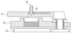
더 상세하게는, 도 3에 나타낸 바와 같이, 종래의 정류기(20)는 절연체(23) 위에 히트싱크(22)와 터미널 어셈블리(21)가 차례로 적층되듯이 결합되어 있으며, 그 중앙 부분에는 다이오드(31)가 배치되어 있다.3, the
그러나 종래의 발전기(10)는, 그 고속으로 회전운동하는 특성상 강한 진동을 수반하게 되는데 비하여, 상기한 바와 같은 종래의 정류기(20)는, 도 3에 나타낸 바와 같이, 터미널(21)과 히트싱크(22) 사이에 별다른 결합구조가 형성되어 있지 아니하므로, 두 부품간의 유격이나 또는 진동에 의한 흔들림으로 결합이 느슨해져 두 부품간에 횡방향이나 종방향 또는 종횡으로 상호운동이 발생하게 되고, 발전기의 회전과 같은 가혹한 진동조건 하에서 그러한 현상이 지속됨으로 인해 심한 경우 부품이 파손되어 버리는(broken) 불량이 발생하는 경우가 있었다.3, the
또한, 상기한 바와 같은 터미널(21)과 히트싱크(22)의 상호 횡운동에 의하여, 도 3에 나타낸 바와 같이 설치되어 있는 다이오드(31)의 리드선(32)이 끊어지는 불량이 발생하는 경우도 빈번하였다.In addition, when the
따라서 상기한 바와 같은 문제를 해결하여 발전기의 회전과 같은 가혹한 진동조건 하에서도 부품간의 유격이나 진동에 의한 흔들림으로 결합이 느슨해져 상호운동이 발생하게 되고 그로 인해 부품이 파손되어 버리는 문제를 해결하는 동시에, 정류기에 설치된 다이오드의 리드선이 끊어지는 불량이 발생하지 않도록 할 수 있는 새로운 정류기의 구성을 가지는 차량용 발전기를 제공하는 것이 바람직하나, 아직까지 그러한 요구를 모두 만족시키는 장치나 방법은 제공되지 못하고 있는 실정이다.Therefore, it is possible to solve the above-mentioned problem and solve the problem that the joints are loosened due to clearance or vibrations between the parts even under severe vibration conditions such as rotation of the generator, mutual movement occurs, It is desirable to provide a generator for a vehicle having a new rectifier configuration capable of preventing defects such as disconnection of the lead wire of a diode installed in a rectifier, but a device or a method that satisfies all of such requirements has not yet been provided .
본 발명은 상기한 바와 같은 종래의 차량용 발전기의 문제점을 해결하기 위한 것으로, 터미널과 히트싱크 사이에 별다른 결합구조가 형성되어 있지 아니하여 두 부품간의 유격이나 또는 진동에 의한 흔들림으로 결합이 느슨해져 상호운동이 발생하게 되고, 발전기의 회전과 같은 가혹한 진동조건 하에서 그러한 현상이 지속됨으로 인해 부품이 파손되어 버리는 불량이 발생하는 것을 방지할 수 있도록, 새로운 결합구조를 통하여 내진동성이 향상된 정류기를 가지는 차량용 발전기를 제공하고자 하는 것이다.SUMMARY OF THE INVENTION Accordingly, the present invention has been made in an effort to solve the problems of the conventional automotive generator as described above, and it is an object of the present invention to provide a vehicular generator having a structure in which a coupling structure is not formed between a terminal and a heat sink, A generator for a vehicle having a rectifier improved in vibration resistance through a new coupling structure so as to prevent the occurrence of defective parts from being damaged due to the continuation of such a phenomenon under severe vibration conditions such as rotation of the generator, .
또한, 본 발명의 다른 목적은, 터미널과 히트싱크의 상호 횡운동에 의하여 정류기에 설치되어 있는 다이오드의 리드선이 끊어지는 것과 같은 불량이 발생하는 것을 미연에 방지할 수 있는 새로운 정류기의 구성을 제시하여, 내진동성이 향상된 정류기를 가지는 차량용 발전기를 제공하고자 하는 것이다.Another object of the present invention is to provide a novel rectifier structure which can prevent a defect such as a break of a lead wire of a diode installed in a rectifier by mutual lateral movement of a terminal and a heat sink , And a generator for a vehicle having a rectifier improved in vibration resistance.
상기한 바와 같은 목적을 달성하기 위해, 본 발명에 따르면, 내진동성이 향상된 정류기를 가지는 차량용 발전기(alternator)에 있어서, 상기 정류기는, 상기 발전기의 전기적인 회로를 구성하도록 연결해 주는 역할을 하는 터미널 어셈블리(Terminal asm)와, 상기 발전기의 방열을 위한 히트싱크(heat sink)와, 상기 히트싱크의 쇼트(short)를 방지하기 위한 절연체(insulator) 및 정류용의 다이오드를 포함하여 구성되고, 상기 터미널 어셈블리는, 그 하측으로 돌출되어 형성되는 결합돌기를 더 포함하며, 상기 히트싱크는, 상기 결합돌기와 결합하는 결합공을 더 포함하고, 상기 터미널 어셈블리와 상기 히트싱크는, 상기 결합공에 상기 결합돌기를 결합함으로써 서로 결합하여 고정되며, 그것에 의해, 상기 터미널 어셈블리와 상기 히트싱크가 상기 발전기의 동작에 수반하는 진동에 의해 상호 운동하는 것을 방지하도록 구성된 것을 특징으로 하는 내진동성이 향상된 정류기를 가지는 차량용 발전기가 제공된다.In order to achieve the above object, according to the present invention, there is provided an alternator for a vehicle having a rectifier improved in vibration resistance, the rectifier including: a terminal assembly for connecting an electric circuit of the generator, A heat sink for heat dissipation of the generator, an insulator for preventing a short of the heat sink, and a diode for rectification, the terminal assembly comprising: Wherein the heat sink further includes a coupling hole for coupling with the coupling projection, wherein the terminal assembly and the heat sink are coupled to each other by a coupling protrusion formed on the coupling hole, So that the terminal assembly and the heat sink can be fixed to the operation of the generator The vehicle generator is provided with improved vibration resistance is a rectifier, characterized in that is configured to prevent the mutual movement by vibration.
여기서, 상기 결합돌기는, 그 원주 방향으로 적어도 하나 이상의 돌기들이 돌출되어 형성되고, 상기 돌기들에 의해 상기 결합공과 강제 끼움 식으로 조립됨으로써 횡방향에 대한 상호운동을 방지하도록 구성되고, 또한, 상기 결합돌기는, 성형툴을 이용하여 그 하단면을 가공하여 변형시킴으로써 상기 결합돌기의 측면 전체가 상기 결합공의 벽면에 밀착하도록 구성되며, 그것에 의해, 상기 터미널 어셈블리와 상기 히트싱크가 횡방향 뿐만 아니라 종방향으로도 상호운동하는 것을 방지하여 더욱 견고한 결합구조를 형성할 수 있도록 구성된 것을 특징으로 한다.Here, the engaging projection is formed by protruding at least one protrusion in the circumferential direction thereof, and is configured to be prevented from mutual movement with respect to the transverse direction by being assembled with the engaging hole in a forced fitting manner by the protrusions, The engaging projection is configured such that the entire side surface of the engaging projection closely contacts the wall surface of the engaging hole by deforming the lower end face of the engaging projection by using a molding tool so that the terminal assembly and the heat sink are So that mutual movement is prevented even in the longitudinal direction, so that a more rigid coupling structure can be formed.
여기서, 상기 성형툴은 히터(heater)나 초음파 융착기를 이용하는 것을 특징으로 한다.Here, the forming tool is characterized by using a heater or an ultrasonic welder.
또한, 상기 결합공을 관통하여 상기 히트싱크의 하부에 돌출되는 상기 결합돌기의 부분을 h라 할 때, 항상 h>0인 조건을 만족하도록 상기 결합돌기를 형성하고, 상기 h만큼 돌출된 부분을 상기 성형툴로 가공하여 상기 히트싱크의 하면에 밀착하도록 변형함으로써 결합강도를 더욱 증대시키도록 구성된 것을 특징으로 한다.In addition, when the portion of the engaging projection projecting to the lower portion of the heat sink through the engaging hole is h, the engaging projection is formed so as to satisfy the condition that h > 0, And is formed so as to be in close contact with the lower surface of the heat sink, thereby further increasing the bonding strength.
여기서, 상기 성형툴의 형태는 원뿔형인 것을 특징으로 한다.Here, the shape of the molding tool is conical.
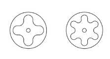
아울러, 상기 성형툴의 형태는, 상기 원뿔형 이외에도, 그 단면이 별모양이나 뿔 모양과 같이, 상기 결합돌기의 변형을 통하여 결합력을 더욱 높일 수 있도록 여러 가지 모양의 성형툴을 선택하여 이용할 수 있는 것을 특징으로 한다.In addition, the shape of the forming tool may be selected from a variety of molding tools such as a star shape or a horn shape, in addition to the conical shape, so that the bonding force can be further increased through deformation of the coupling protrusion .
상기한 바와 같이, 본 발명에 따르면, 종래의 차량용 발전기의 정류기에서는, 터미널과 히트싱크 사이에 별다른 결합구조가 형성되어 있지 아니하여 두 부품간의 유격이나 또는 진동에 의한 흔들림으로 결합이 느슨해져 상호운동이 발생하게 되고, 발전기의 회전과 같은 가혹한 진동조건 하에서 그러한 현상이 지속됨으로 인해 부품이 파손되어 버리는 불량이 발생하였던 문제를 해결하여, 발전기의 회전과 같은 가혹한 진동조건 하에서도 부품간의 상호운동으로 인해 부품이 파손되는 불량을 미연에 방지할 수 있는 새로운 내진동성이 향상된 정류기를 가지는 차량용 발전기를 제공할 수 있다.As described above, according to the present invention, in the conventional rectifier for a vehicular generator, since no coupling structure is formed between the terminal and the heat sink, the coupling is loosened due to clearance between the two parts or vibration, This problem is solved by the fact that such a phenomenon continues under severe vibration conditions such as the rotation of a generator, thereby causing a problem that the parts are broken. Thus, even under severe vibration conditions such as the rotation of a generator, It is possible to provide a vehicular generator having a new rectifier with improved vibration resistance that can prevent the breakage failure.
또한, 본 발명에 따르면, 터미널과 히트싱크의 상호 횡운동에 의하여 정류기에 설치되어 있는 다이오드의 리드선이 끊어지는 것과 같은 불량이 발생하는 것을 미연에 방지할 수 있는 새로운 내진동성이 향상된 정류기를 가지는 차량용 발전기를 제공할 수 있다.Further, according to the present invention, it is possible to prevent the occurrence of defects such as the breakage of the lead wire of the diode installed in the rectifier due to the mutual lateral movement of the terminal and the heat sink, Generator can be provided.
도 1은 종래의 차량용 발전기의 전체적인 구성을 개략적으로 나타내는 단면도이다.
도 2는 종래의 차량용 발전기에 이용되는 정류기의 구성을 개략적으로 나타내는 평면도이다.
도 3은 도 2에 나타낸 정류기의 상세한 구성을 나타내는 단면도이다.
도 4는 본 발명에 따른 내진동성이 향상된 정류기를 가지는 차량용 발전기에 이용되는 정류기의 구성을 나타내는 단면도이다.
도 5는 본 발명에 따른 내진동성이 향상된 정류기를 가지는 차량용 발전기에 이용되는 정류기의 다른 구성을 나타내는 단면도이다.
도 6은 본 발명에 따른 내진동성이 향상된 정류기를 가지는 차량용 발전기에 이용되는 정류기의 또 다른 구성을 나타내는 단면도이다.
도 7은 본 발명에 따른 내진동성이 향상된 정류기를 가지는 차량용 발전기에 이용되는 정류기를 성형하기 위한 성형툴의 다른 구성을 나타내는 도면이다.1 is a cross-sectional view schematically showing the overall structure of a conventional automotive generator.
2 is a plan view schematically showing a configuration of a rectifier used in a conventional automotive generator.
3 is a cross-sectional view showing a detailed configuration of the rectifier shown in Fig.
4 is a cross-sectional view showing a configuration of a rectifier used in a vehicle generator having a rectifier improved in vibration resistance according to the present invention.
5 is a cross-sectional view showing another configuration of a rectifier used in a vehicle generator having a rectifier improved in vibration resistance according to the present invention.
6 is a cross-sectional view showing still another configuration of a rectifier used in a vehicle generator having a rectifier improved in vibration resistance according to the present invention.
7 is a view showing another configuration of a molding tool for molding a rectifier used in a vehicle generator having a rectifier improved in vibration resistance according to the present invention.
이하, 첨부된 도면을 참조하여 본 발명에 따른 내진동성이 향상된 정류기를 가지는 차량용 발전기의 상세한 내용에 대하여 설명한다.DETAILED DESCRIPTION OF THE PREFERRED EMBODIMENTS Hereinafter, a vehicle generator having a rectifier with improved vibration resistance according to the present invention will be described in detail with reference to the accompanying drawings.
여기서, 이하에 설명하는 내용은 본 발명을 실시하기 위한 하나의 실시예일 뿐이며, 본 발명은 이하에 설명하는 실시예의 내용으로만 한정되는 것은 아니다.Hereinafter, the following description is only an embodiment for carrying out the present invention, and the present invention is not limited to the contents of the embodiments described below.
먼저, 도 4를 참조하면, 도 4는 본 발명에 따른 내진동성이 향상된 정류기를 가지는 차량용 발전기에 사용되는 정류기의 전체적인 구성을 개략적으로 나타내고 있다.4, a general configuration of a rectifier used in a vehicle generator having a rectifier improved in vibration resistance according to the present invention is schematically shown in FIG.
즉, 도 4에 나타낸 바와 같이, 본 발명에 따른 내진동성이 향상된 정류기를 가지는 차량용 발전기에 이용되는 정류기(40)의 구성은, 기본적으로는, 발전기의 전기적인 회로를 구성하도록 연결해 주는 역할을 하는 터미널 어셈블리(Terminal asm)(41)와, 발전기의 방열을 위한 히트싱크(heatsink)(42)와, 히트싱크의 쇼트(short)를 방지하기 위한 절연체(insulator)(43) 및 정류용의 다이오드(44)와 그 리드선(45)을 포함하여 이루어지는 구조인 것만 보면 상기한 바와 같은 종래의 정류기(20)와 동일하나, 본 발명에 따른 내진동성이 향상된 정류기(40)는, 후술하는 바와 같이, 터미널 어셈블리(41)와 히트싱크(42)가 서로 결합하는 결합구조를 더 포함하고 있는 점이 상기한 바와 같은 종래의 정류기(20)와 다르다.That is, as shown in Fig. 4, the configuration of the rectifier 40 used in the automotive generator having the rectifier improved in vibration resistance according to the present invention basically serves to connect the electrical circuit of the generator
더 상세하게는, 도 4의 원으로 나타낸 확대도에 나타낸 바와 같이, 터미널 어셈블리(41)에 아래쪽으로 길게 돌출하도록 결합돌기(46)를 형성하고, 히트싱크(42)에는 결합공(47)을 형성하여, 도 4에 나타낸 바와 같이 터미널 어셈블리(41)에 형성된 결합돌기(46)가 히트싱크(42)에 형성된 결합공(47)에 맞물리도록 하여 결합함으로써, 터미널 어셈블리(41)와 히트싱크(42)가 서로 견고하게 고정되도록 한다.More specifically, as shown in the enlarged view of FIG. 4, a
여기서, 도 4의 원으로 나타낸 확대도에 나타낸 바와 같이, 결합공(47)의 지름(D1)보다 결합돌기(46)의 지름(D2)을 크게 함으로써, 터미널 어셈블리(41)와 히트싱크(42)의 상호 운동을 보다 확실하게 방지할 수 있다.4, the diameter D2 of the
즉, 도 4에 나타낸 바와 같이, 결합돌기(46)의 원주 방향으로 복수의 돌기들이 돌출되어 있고, 이와 같이 돌출한 돌기들에 의해 결합공과 강제 끼움 식으로 조립됨으로써 횡방향에 대한 상호운동을 보다 확실하게 방지할 수 있게 된다.4, a plurality of protrusions protrude in the circumferential direction of the
상기한 바와 같이, 터미널 어셈블리(41)에 결합돌기(46)를 형성하고, 히트싱크(42)에는 결합공(47)을 형성하여, 이들을 서로 결합함으로써 터미널 어셈블리(41)와 히트싱크(42)를 고정할 수 있으나, 상기한 도 4에 나타낸 구성만으로는, 좌우 횡방향으로의 움직임은 방지할 수 있으나, 예를 들면, 세로 방향(종방향)으로 힘이 가해졌을 때에는, 터미널 어셈블리(41)와 히트싱크(42) 사이의 결합력이 유지되지 못하는 구조이므로, 도 4에 나타낸 구조만으로는 상하운동과 같은 종방향으로의 움직임까지 방지하는 것은 어렵다.As described above, the
따라서, 도 5에 나타낸 바와 같이, 예를 들면, 히터(heater)나 초음파 융착기와 같은 성형툴(51)을 이용하여, 터미널 어셈블리(41)에 형성된 결합돌기(46)의 하단부를 변형시켜 상하방향으로도 클램핑(clamping)이 가능하도록 하는 것이 바람직하다.5, the lower ends of the
즉, 도 5에 나타낸 바와 같이, 터미널 어셈블리(41)에 형성된 결합돌기(46)의 하단부를 성형툴(51)을 이용하여 결합돌기(46)의 측면 전체가 결합공(47)의 벽면에 밀착하도록 변형시킴으로써, 상하방향에 대하여도 결합강도를 높여 횡방향 뿐만 아니라 종방향으로도 더욱 견고한 결합구조를 형성할 수 있다.5, the entire lower surface of the
아울러, 더욱 바람직하게는, 도 6에 나타낸 바와 같이, 결합돌기(46)의 길이를 결합공(47)을 관통하도록 충분히 길게 형성하고, 도 5에 나타낸 바와 같은 가공을 행하여 히트싱크(42)의 하면에 밀착하도록 성형하면, 보다 더 확실한 결합강도를 가지는 결합구조를 얻을 수 있다.More preferably, as shown in Fig. 6, the length of the
즉, 도 6에 나타낸 바와 같이, 결합공(47)을 관통하여 히트싱크(42)의 하부에 돌출되는 결합돌기(46)의 부분의 두께를 h라 하면, 항상 h>0인 조건을 만족하도록 결합돌기(43)를 형성하고, 상기한 바와 같이 h만큼 돌출된 부분을 가공하여 히트싱크(42)의 하면에 밀착하도록 변형하면, 히트싱크(42)의 상하방향에서 클램핑 하는 힘이 더욱 증대된다.That is, as shown in Fig. 6, when the thickness of the portion of the
따라서 상기한 바와 같이, 도 4 내지 도 6에 나타낸 구성을 통하여, 터미널 어셈블리와 히트싱크 사이에 별다른 결합구조가 형성되어 있지 않아 발전기의 회전과 같은 진동조건 하에서 두 부품간의 유격이나 진동에 의한 흔들림으로 결합이 느슨해져 상호운동이 발생하게 되고, 그러한 현상이 반복됨으로 인해 부품이 파손되어 버리는 종래의 차량용 발전기의 정류기의 문제를 해결하여, 발전기의 동작에 수반하는 진동에 의해 부품간의 상호운동이 발생하여 부품이 파손되는 불량을 미연에 방지할 수 있다.4 to 6, there is no particular coupling structure between the terminal assembly and the heat sink, so that vibration due to clearance or vibration between the two components under vibration conditions such as rotation of the generator The problem of the rectifier of the conventional automotive generator in which the parts are broken due to the repetition of such phenomenon is solved and the mutual motion of the parts occurs due to the vibration accompanying the operation of the generator, It is possible to prevent defective failure.
또한, 상기한 바와 같은 구성을 통하여, 터미널 어셈블리와 히트싱크의 상호 횡운동에 의하여 정류기에 설치되어 있는 다이오드의 리드선이 끊어지는 것과 같은 불량이 발생하는 것도 방지할 수 있다.Also, through the above-described configuration, it is possible to prevent defects such as breakage of the lead wire of the diode installed in the rectifier due to mutual lateral movement of the terminal assembly and the heat sink.
이상, 상기한 바와 같은 본 발명의 실시예를 통하여 본 발명을 설명하였으나, 본 발명은 상기한 실시예에 기재된 내용으로만 한정되는 것은 아니다.While the present invention has been particularly shown and described with reference to exemplary embodiments thereof, it is to be understood that the invention is not limited to the disclosed exemplary embodiments.
즉, 상기한 설명에서는, 도 5에 나타낸 성형툴(51)의 형태가 원뿔형의 깔대기 모양인 것으로 나타내었으나, 이러한 모양 이외에도, 예를 들면, 도 7에 나타낸 바와 같이, 단면이 별모양이나 뿔 모양 등의 여러 가지 모양의 성형툴을 이용하여 결합돌기(46)의 변형을 더 깊게 함으로써 결합력을 더욱 높일 수 있다.That is, in the above description, although the shape of the
따라서 상기한 바와 같이, 본 발명은 상기한 실시예에 기재된 내용으로만 한정되는 것이 아니라, 본 발명이 속하는 기술분야에서 통상의 지식을 가진 자에 의해 설계상의 필요 및 기타 다양한 요인에 따라 여러 가지 수정, 변경, 결합 및 대체 등이 가능한 것임은 당연한 일이라 하겠다.Therefore, it should be understood that the present invention is not limited to the details of the foregoing embodiment, but various changes and modifications may be made by those skilled in the art depending on design requirements and various other factors. , Change, combination and substitution are possible.
10. 차량용 발전기 20. 정류기
21. 터미널 22. 히트싱크
23. 절연체 31. 다이오드
32. 리드선 40. 정류기
41. 터미널 어셈블리 42. 히트싱크
43. 절연체 44. 다이오드
45. 리드선 46. 결합돌기
47. 결합공 51. 성형툴10.
21.
23.
32. Lead Wire 40. Rectifier
41.
43.
45.
47. Coupling
Claims (6)
Translated fromKorean상기 정류기는,
상기 발전기의 전기적인 회로를 구성하도록 연결해 주는 역할을 하는 터미널 어셈블리(Terminal asm)와,
상기 발전기의 방열을 위한 히트싱크(heat sink)와,
상기 히트싱크의 쇼트(short)를 방지하기 위한 절연체(insulator) 및
정류용의 다이오드를 포함하여 구성되고,
상기 터미널 어셈블리는, 그 하측으로 돌출되어 형성되고 그 원주 방향으로 적어도 하나 이상의 돌기들이 돌출되어 형성되는 결합돌기를 더 포함하며,
상기 히트싱크는, 상기 결합돌기와 결합하는 결합공을 더 포함하고,
상기 터미널 어셈블리는 상기 절연체와 일측이 연결되고,
상기 정류용의 다이오드는 상기 터미널 어셈블리를 관통하며,
상기 터미널 어셈블리와 상기 히트싱크는, 상기 결합공에 상기 결합돌기를 결합함으로써 서로 결합하여 고정되고,
상기 결합공과 결합돌기가 결합되는 부분은 상기 터미널 어셈블리와 상기 절연체가 연결된 일측에서 정류용 다이오드를 마주하여 위치하는 일측이며,
그것에 의해, 상기 터미널 어셈블리와 상기 히트싱크가 상기 발전기의 동작에 수반하는 진동에 의해 상호 운동하는 것을 방지하도록 구성된 것을 특징으로 하는 내진동성이 향상된 정류기를 가지는 차량용 발전기.An alternator for a vehicle having a rectifier improved in vibration resistance,
The rectifier includes:
A terminal assembly (terminal asm) for connecting the generator to the generator,
A heat sink for dissipating heat of the generator,
An insulator for preventing a short of the heat sink, and
And a rectifier diode,
The terminal assembly further includes an engaging protrusion protruding downwardly and formed by protruding at least one protrusion in a circumferential direction of the terminal assembly,
Wherein the heat sink further comprises a coupling hole for coupling with the coupling projection,
Wherein the terminal assembly is connected to the insulator at one side,
The rectifier diode passes through the terminal assembly,
Wherein the terminal assembly and the heat sink are fixed to each other by engaging the engaging projections with the engaging holes,
Wherein a portion where the coupling hole and the coupling protrusion are coupled is one side facing the rectifier diode on one side where the terminal assembly and the insulator are connected,
Whereby the terminal assembly and the heat sink are prevented from mutual movement due to vibrations caused by the operation of the generator.
상기 결합돌기는 돌기들에 의해 상기 결합공과 강제 끼움 식으로 조립됨으로써 횡방향에 대한 상호운동을 방지하도록 구성되고,
또한, 상기 결합돌기는, 성형툴을 이용하여 그 하단면을 가공하여 변형시킴으로써 상기 결합돌기의 측면 전체가 상기 결합공의 벽면에 밀착하도록 구성되며,
그것에 의해, 상기 터미널 어셈블리와 상기 히트싱크가 횡방향 뿐만 아니라 종방향으로도 상호운동하는 것을 방지하여 더욱 견고한 결합구조를 형성할 수 있도록 구성된 것을 특징으로 하는 내진동성이 향상된 정류기를 가지는 차량용 발전기.The method according to claim 1,
Wherein the engaging projections are configured to be prevented from mutual movement in the lateral direction by being assembled with the engaging holes by the projections in a forced fit manner,
The engaging projection may be formed by deforming a lower end surface of the engaging projection by using a forming tool so that the entire side surface of the engaging projection closely contacts the wall surface of the engaging hole,
Thereby preventing the terminal assembly and the heat sink from mutually moving in the longitudinal direction as well as in the transverse direction, thereby forming a more rigid coupling structure.
상기 성형툴은 히터(heater)나 초음파 융착기를 이용하는 것을 특징으로 하는 내진동성이 향상된 정류기를 가지는 차량용 발전기.3. The method of claim 2,
Wherein the molding tool uses a heater or an ultrasonic welder.
상기 결합공을 관통하여 상기 히트싱크의 하부에 돌출되는 상기 결합돌기의 부분을 h라 할 때, 항상 h>0인 조건을 만족하도록 상기 결합돌기를 형성하고,
상기 h만큼 돌출된 부분을 상기 성형툴로 가공하여 상기 히트싱크의 하면에 밀착하도록 변형함으로써 결합강도를 더욱 증대시키도록 구성된 것을 특징으로 하는 내진동성이 향상된 정류기를 가지는 차량용 발전기.The method of claim 3,
When the portion of the engaging projection projecting to the lower portion of the heat sink through the engaging hole is h, the engaging projection is formed so as to satisfy the condition of h > 0 at all times,
And a portion protruding by h is formed by the forming tool so as to be closely contacted with the lower surface of the heat sink, thereby further increasing the coupling strength.
상기 성형툴의 형태는 원뿔형인 것을 특징으로 하는 내진동성이 향상된 정류기를 가지는 차량용 발전기.5. The method of claim 4,
Wherein the shape of the molding tool is a conical shape.
상기 성형툴의 형태는, 상기 원뿔형 이외에도, 그 단면이 별모양이나 뿔 모양과 같이, 상기 결합돌기의 변형을 통하여 결합력을 더욱 높일 수 있도록 여러 가지 모양의 성형툴을 선택하여 이용할 수 있는 것을 특징으로 하는 내진동성이 향상된 정류기를 가지는 차량용 발전기.
6. The method of claim 5,
The shape of the molding tool may be selected from a variety of molding tools such as a star shape or a horn shape in addition to the conical shape so that the bonding force can be further increased through deformation of the coupling protrusion Wherein the rectifier has an improved vibration resistance.
Priority Applications (1)
| Application Number | Priority Date | Filing Date | Title |
|---|---|---|---|
| KR1020100045056AKR101598566B1 (en) | 2010-05-13 | 2010-05-13 | An alternator having a rectifier with an improved vibration resistance |
Applications Claiming Priority (1)
| Application Number | Priority Date | Filing Date | Title |
|---|---|---|---|
| KR1020100045056AKR101598566B1 (en) | 2010-05-13 | 2010-05-13 | An alternator having a rectifier with an improved vibration resistance |
Publications (2)
| Publication Number | Publication Date |
|---|---|
| KR20110125493A KR20110125493A (en) | 2011-11-21 |
| KR101598566B1true KR101598566B1 (en) | 2016-02-29 |
Family
ID=45394930
Family Applications (1)
| Application Number | Title | Priority Date | Filing Date |
|---|---|---|---|
| KR1020100045056AActiveKR101598566B1 (en) | 2010-05-13 | 2010-05-13 | An alternator having a rectifier with an improved vibration resistance |
Country Status (1)
| Country | Link |
|---|---|
| KR (1) | KR101598566B1 (en) |
Citations (3)
| Publication number | Priority date | Publication date | Assignee | Title |
|---|---|---|---|---|
| JP2002289276A (en) | 2001-03-26 | 2002-10-04 | Densei Lambda Kk | Terminal structure of electronic equipment |
| KR100642198B1 (en)* | 2005-11-07 | 2006-11-02 | 에이테크솔루션(주) | Caulking assembly in which the shaft and thrust plate of the spindle motor are caulked and its manufacturing method |
| JP2006353067A (en)* | 2005-06-20 | 2006-12-28 | Asmo Co Ltd | Control circuit unit for motor and manufacturing method therefor, and motor equipped with the control circuit unit for motor |
Family Cites Families (1)
| Publication number | Priority date | Publication date | Assignee | Title |
|---|---|---|---|---|
| KR100777918B1 (en)* | 2005-11-10 | 2007-11-21 | 한국델파이주식회사 | Method for Manufacturing Terminal Assembly of an Alternator for a Vehicle and Terminal Assembly thereof |
- 2010
- 2010-05-13KRKR1020100045056Apatent/KR101598566B1/enactiveActive
Patent Citations (3)
| Publication number | Priority date | Publication date | Assignee | Title |
|---|---|---|---|---|
| JP2002289276A (en) | 2001-03-26 | 2002-10-04 | Densei Lambda Kk | Terminal structure of electronic equipment |
| JP2006353067A (en)* | 2005-06-20 | 2006-12-28 | Asmo Co Ltd | Control circuit unit for motor and manufacturing method therefor, and motor equipped with the control circuit unit for motor |
| KR100642198B1 (en)* | 2005-11-07 | 2006-11-02 | 에이테크솔루션(주) | Caulking assembly in which the shaft and thrust plate of the spindle motor are caulked and its manufacturing method |
Also Published As
| Publication number | Publication date |
|---|---|
| KR20110125493A (en) | 2011-11-21 |
Similar Documents
| Publication | Publication Date | Title |
|---|---|---|
| JP6345300B2 (en) | Power semiconductor device, power semiconductor device embedded device, and manufacturing method of power semiconductor device embedded device | |
| KR101186781B1 (en) | Power semiconductor circuit device and method for manufacturing the same | |
| US9455215B2 (en) | Semiconductor device and method for manufacturing the same | |
| CN104838493A (en) | Power module | |
| JP5213919B2 (en) | Semiconductor device | |
| CN1879212B (en) | diode | |
| US9554492B2 (en) | Power converter | |
| US9484294B2 (en) | Semiconductor device and method of manufacturing the same | |
| WO2018020640A1 (en) | Semiconductor device | |
| JP6010942B2 (en) | Semiconductor device and manufacturing method thereof | |
| KR101598566B1 (en) | An alternator having a rectifier with an improved vibration resistance | |
| KR20080097341A (en) | Light emitting device and manufacturing method thereof | |
| JP2010003858A (en) | Semiconductor device | |
| JP6567957B2 (en) | Power semiconductor module manufacturing method | |
| JP2012238749A (en) | Semiconductor device | |
| CN115398750A (en) | Connecting device and method for connecting connecting device to component | |
| JP2017188528A (en) | Semiconductor device | |
| JP6400206B2 (en) | Semiconductor device | |
| KR20150002593U (en) | Power converter | |
| JP4131390B2 (en) | Fixing method of press-fit type semiconductor module | |
| JP2009284600A (en) | Circuit structure and electrical junction box | |
| KR101311539B1 (en) | Diode Package | |
| JP2002314035A (en) | Power semiconductor module | |
| JP5496304B2 (en) | Semiconductor device | |
| KR100344226B1 (en) | Head pin of rectifier diode |
Legal Events
| Date | Code | Title | Description |
|---|---|---|---|
| PA0109 | Patent application | Patent event code:PA01091R01D Comment text:Patent Application Patent event date:20100513 | |
| PG1501 | Laying open of application | ||
| A201 | Request for examination | ||
| PA0201 | Request for examination | Patent event code:PA02012R01D Patent event date:20140714 Comment text:Request for Examination of Application Patent event code:PA02011R01I Patent event date:20100513 Comment text:Patent Application | |
| E902 | Notification of reason for refusal | ||
| PE0902 | Notice of grounds for rejection | Comment text:Notification of reason for refusal Patent event date:20150828 Patent event code:PE09021S01D | |
| E701 | Decision to grant or registration of patent right | ||
| PE0701 | Decision of registration | Patent event code:PE07011S01D Comment text:Decision to Grant Registration Patent event date:20160216 | |
| GRNT | Written decision to grant | ||
| PR0701 | Registration of establishment | Comment text:Registration of Establishment Patent event date:20160223 Patent event code:PR07011E01D | |
| PR1002 | Payment of registration fee | Payment date:20160224 End annual number:3 Start annual number:1 | |
| PG1601 | Publication of registration | ||
| FPAY | Annual fee payment | Payment date:20181211 Year of fee payment:4 | |
| PR1001 | Payment of annual fee | Payment date:20181211 Start annual number:4 End annual number:4 | |
| FPAY | Annual fee payment | Payment date:20191210 Year of fee payment:5 | |
| PR1001 | Payment of annual fee | Payment date:20191210 Start annual number:5 End annual number:5 | |
| PR1001 | Payment of annual fee | Payment date:20201209 Start annual number:6 End annual number:6 | |
| PR1001 | Payment of annual fee | Payment date:20211206 Start annual number:7 End annual number:7 | |
| PR1001 | Payment of annual fee | Payment date:20221207 Start annual number:8 End annual number:8 |