KR101595384B1 - Watch type mobile terminal - Google Patents
Watch type mobile terminalDownload PDFInfo
- Publication number
- KR101595384B1 KR101595384B1KR1020090066028AKR20090066028AKR101595384B1KR 101595384 B1KR101595384 B1KR 101595384B1KR 1020090066028 AKR1020090066028 AKR 1020090066028AKR 20090066028 AKR20090066028 AKR 20090066028AKR 101595384 B1KR101595384 B1KR 101595384B1
- Authority
- KR
- South Korea
- Prior art keywords
- buckle
- unit
- main body
- band
- slider
- Prior art date
- Legal status (The legal status is an assumption and is not a legal conclusion. Google has not performed a legal analysis and makes no representation as to the accuracy of the status listed.)
- Expired - Fee Related
Links
Images


Classifications
- H—ELECTRICITY
- H04—ELECTRIC COMMUNICATION TECHNIQUE
- H04B—TRANSMISSION
- H04B1/00—Details of transmission systems, not covered by a single one of groups H04B3/00 - H04B13/00; Details of transmission systems not characterised by the medium used for transmission
- H04B1/38—Transceivers, i.e. devices in which transmitter and receiver form a structural unit and in which at least one part is used for functions of transmitting and receiving
- G—PHYSICS
- G04—HOROLOGY
- G04G—ELECTRONIC TIME-PIECES
- G04G21/00—Input or output devices integrated in time-pieces
- G04G21/02—Detectors of external physical values, e.g. temperature
- G—PHYSICS
- G04—HOROLOGY
- G04G—ELECTRONIC TIME-PIECES
- G04G21/00—Input or output devices integrated in time-pieces
- G04G21/04—Input or output devices integrated in time-pieces using radio waves
- G—PHYSICS
- G06—COMPUTING OR CALCULATING; COUNTING
- G06F—ELECTRIC DIGITAL DATA PROCESSING
- G06F1/00—Details not covered by groups G06F3/00 - G06F13/00 and G06F21/00
- G06F1/16—Constructional details or arrangements
- G06F1/1613—Constructional details or arrangements for portable computers
- G06F1/163—Wearable computers, e.g. on a belt
- H—ELECTRICITY
- H04—ELECTRIC COMMUNICATION TECHNIQUE
- H04M—TELEPHONIC COMMUNICATION
- H04M1/00—Substation equipment, e.g. for use by subscribers
- H04M1/02—Constructional features of telephone sets
- H—ELECTRICITY
- H04—ELECTRIC COMMUNICATION TECHNIQUE
- H04M—TELEPHONIC COMMUNICATION
- H04M1/00—Substation equipment, e.g. for use by subscribers
- H04M1/02—Constructional features of telephone sets
- H04M1/23—Construction or mounting of dials or of equivalent devices; Means for facilitating the use thereof
- H—ELECTRICITY
- H04—ELECTRIC COMMUNICATION TECHNIQUE
- H04M—TELEPHONIC COMMUNICATION
- H04M1/00—Substation equipment, e.g. for use by subscribers
- H04M1/26—Devices for calling a subscriber
- H04M1/27—Devices whereby a plurality of signals may be stored simultaneously
- H04M1/274—Devices whereby a plurality of signals may be stored simultaneously with provision for storing more than one subscriber number at a time, e.g. using toothed disc
- H04M1/2745—Devices whereby a plurality of signals may be stored simultaneously with provision for storing more than one subscriber number at a time, e.g. using toothed disc using static electronic memories, e.g. chips
- H04M1/27467—Methods of retrieving data
- H04M1/2747—Scrolling on a display
- H—ELECTRICITY
- H04—ELECTRIC COMMUNICATION TECHNIQUE
- H04M—TELEPHONIC COMMUNICATION
- H04M1/00—Substation equipment, e.g. for use by subscribers
- H04M1/72—Mobile telephones; Cordless telephones, i.e. devices for establishing wireless links to base stations without route selection
- H04M1/724—User interfaces specially adapted for cordless or mobile telephones
- H04M1/72403—User interfaces specially adapted for cordless or mobile telephones with means for local support of applications that increase the functionality
- H—ELECTRICITY
- H04—ELECTRIC COMMUNICATION TECHNIQUE
- H04W—WIRELESS COMMUNICATION NETWORKS
- H04W52/00—Power management, e.g. Transmission Power Control [TPC] or power classes
- H04W52/02—Power saving arrangements
- H04W52/0209—Power saving arrangements in terminal devices
- H04W52/0251—Power saving arrangements in terminal devices using monitoring of local events, e.g. events related to user activity
- H04W52/0254—Power saving arrangements in terminal devices using monitoring of local events, e.g. events related to user activity detecting a user operation or a tactile contact or a motion of the device
- H—ELECTRICITY
- H04—ELECTRIC COMMUNICATION TECHNIQUE
- H04M—TELEPHONIC COMMUNICATION
- H04M2250/00—Details of telephonic subscriber devices
- H04M2250/12—Details of telephonic subscriber devices including a sensor for measuring a physical value, e.g. temperature or motion
- Y—GENERAL TAGGING OF NEW TECHNOLOGICAL DEVELOPMENTS; GENERAL TAGGING OF CROSS-SECTIONAL TECHNOLOGIES SPANNING OVER SEVERAL SECTIONS OF THE IPC; TECHNICAL SUBJECTS COVERED BY FORMER USPC CROSS-REFERENCE ART COLLECTIONS [XRACs] AND DIGESTS
- Y02—TECHNOLOGIES OR APPLICATIONS FOR MITIGATION OR ADAPTATION AGAINST CLIMATE CHANGE
- Y02D—CLIMATE CHANGE MITIGATION TECHNOLOGIES IN INFORMATION AND COMMUNICATION TECHNOLOGIES [ICT], I.E. INFORMATION AND COMMUNICATION TECHNOLOGIES AIMING AT THE REDUCTION OF THEIR OWN ENERGY USE
- Y02D30/00—Reducing energy consumption in communication networks
- Y02D30/70—Reducing energy consumption in communication networks in wireless communication networks
Landscapes
- Engineering & Computer Science (AREA)
- Signal Processing (AREA)
- Physics & Mathematics (AREA)
- General Physics & Mathematics (AREA)
- Computer Networks & Wireless Communication (AREA)
- Computer Hardware Design (AREA)
- Human Computer Interaction (AREA)
- Theoretical Computer Science (AREA)
- General Engineering & Computer Science (AREA)
- Telephone Set Structure (AREA)
Abstract
Translated fromKoreanDescription
Translated fromKorean본 발명은 손목에 착용할 수 있는 와치형 이동 단말기에 관한 것이다.The present invention relates to a watch-type mobile terminal which can be worn on the wrist.
이동 단말기는 휴대가 가능하면서 음성 및 영상 통화 기능, 정보를 입·출력하는 기능 및 데이터를 저장할 수 있는 기능 등을 하나 이상 갖춘 휴대용 기기이다.A mobile terminal is a portable device that is portable and has one or more functions such as voice and video call function, information input / output function, and data storage function.
그리고, 이동 단말기는 기능이 다양화됨에 따라 예를 들어 사진이나 동영상의 촬영, 음악이나 동영상 파일의 재생, 게임, 방송의 수신 등의 복잡한 기능들을 갖추고 있으며, 종합적인 멀티미디어 기기(Multimedia player) 형태로 구현되고 있다.As the functions of the mobile terminal are diversified, for example, the mobile terminal has complicated functions such as photographing and photographing of a moving picture, reproduction of music or video file, reception of a game and broadcasting, and the like in the form of a multimedia player .
또한, 이동 단말기는 자신의 개성을 표현하기 위한 개인 휴대품으로 여겨지면서, 다양한 디자인이 요구되고 있다. 이러한 디자인적 요구는 이동 단말기를 보다 편리하게 사용할 수 있는 구조적인 변화 및 개량을 포함할 수 있다.In addition, mobile terminals are regarded as personal items to express their individuality, and various designs are required. This design requirement may include structural changes and improvements that make the mobile terminal more convenient to use.
이러한 구조적인 변화 및 개량의 하나로 손목에 착용하여 사용할 수 있는 와치형 이동 단말기에 대해 고려될 수 있다. 이러한 와치형 이동 단말기는 이동 단말기의 기능뿐만 아니라 시계로서의 기능이 크므로, 그 사이즈 및 두께를 소형화, 슬 림화 및 디자인의 심플화 등은 와치형 이동 단말기의 설계에 있어 매우 중요시되어야 할 문제이다.Such a structural change and improvement can be considered for a watch-type mobile terminal that can be worn on the wrist. Since the watch-type mobile terminal has a function as a clock as well as a function of a mobile terminal, miniaturization of the size and thickness, simplification of slimming, and simplification of design are very important issues in the design of a watch-type mobile terminal.
본 발명은 상기와 같은 점을 감안하여 안출된 것으로서, 와치형 이동 단말기에 있어 입력수단의 장착 공간을 최소화하여 와치형 이동 단말기의 사이즈 및 두께를 소형화, 슬림화함과 동시에 심플한 디자인을 구현할 수 있는 구조를 제공하기 위한 것이다.SUMMARY OF THE INVENTION The present invention has been made in view of the above-described problems, and it is an object of the present invention to provide a watch structure in which a mounting space of input means is minimized to reduce the size and thickness of the watch- .
또한, 본 발명은 사용자가 와치형 이동 단말기의 전원을 편리하게 온/오프 시킬 수 있는 구조를 제공하기 위한 것이다.The present invention also provides a structure in which a user can conveniently turn on / off the power of the watch-type mobile terminal.
상기한 과제를 실현하기 위한 본 발명은 무선통신모듈을 구비하는 본체와, 상기 본체의 양단에 각각 연결되는 밴드와, 상기 밴드에 장착되며 접속 및 접속 해제 동작에 의해 상기 밴드를 손목에 착탈시키는 버클유닛, 및 상기 버클유닛에 장착되며, 상기 본체에 전기적으로 연결되어 상기 버클유닛의 접속시 상기 본체의 전원을 온(ON) 시키기 위한 신호를 발생시키는 신호 발생부를 포함하는 와치형 이동 단말기를 개시한다.According to an aspect of the present invention, there is provided a wireless communication module including a body having a wireless communication module, a band connected to both ends of the body, and a buckle attached to the band, And a signal generator mounted on the buckle unit and electrically connected to the body to generate a signal for turning on the power of the body when the buckle unit is connected .
상기 버클 유닛은 상기 본체의 일단에 연결된 제1밴드에 연결되는 제1버클부와, 상기 본체의 타단에 연결된 제2밴드에 연결되는 제2버클부, 및 상기 제1 및 제2버클부재를 체결 또는 분리시키는 체결부를 포함할 수 있다. 여기서, 상기 신호 발생부는 상기 제1 및 제2버클부 중 적어도 어느 하나에 배치될 수 있다.The buckle unit includes a first buckle portion connected to a first band connected to one end of the main body, a second buckle portion connected to a second band connected to the other end of the main body, Or detachment of the fastening portion. Here, the signal generating unit may be disposed in at least one of the first and second buckle units.
상기 신호 발생부는 상기 버클유닛의 접속 해제시 상기 본체의 전원을 오 프(OFF)시키도록 구성될 수 있다.The signal generator may be configured to turn off power to the main body when the buckle unit is disconnected.
한편, 본 발명은 무선통신모듈을 구비하는 본체와, 상기 본체의 양단에 각각 연결되는 밴드와, 상기 밴드에 장착되며 상기 밴드를 손목에 착탈시키는 버클유닛, 및 상기 버클유닛의 일면에 장착되며 사용자의 조작에 의해 상기 본체에 정보를 입력하는 조작유닛을 포함하는 와치형 이동 단말기를 개시한다.According to another aspect of the present invention, there is provided a wireless communication module including a body having a wireless communication module, a band connected to both ends of the body, a buckle unit mounted on the band and attaching and detaching the band to and from the wrist, And an operation unit for inputting information to the main body by an operation of the operation unit.
상기 조작유닛은 상기 본체 전원의 온/오프 명령, 통화 명령, 취소 명령, 커서 또는 포인터의 이동 명령, 및 음향 또는 그래픽의 상태량 조절 명령 중 적어도 하나를 상기 본체에 입력하도록 구성될 수 있다.The operation unit may be configured to input to the main body at least one of an on / off command of the main body power supply, a call command, a cancel command, a movement command of a cursor or a pointer,
상기 조작유닛은 상기 본체에 기설정된 작동 모드의 실행 명령을 입력하도록 구성될 수 있다.The operation unit may be configured to input an execution command of a predetermined operation mode to the main body.
상기 조작유닛은 상기 버클유닛의 측면에 누름 동작 가능하게 장착되는 적어도 하나의 키버튼과, 상기 버클유닛 내부의 기판에 장착되며 상기 키버튼이 누름 동작됨에 따라 신호를 발생시키는 스위치를 포함할 수 있다.The operation unit may include at least one key button mounted on a side surface of the buckle unit so as to be pushed and a switch mounted on a substrate inside the buckle unit and generating a signal as the key button is pressed .
상기 조작유닛은 상기 버클유닛의 외면에 슬라이드 가능하게 장착되는 슬라이더와, 상기 버클유닛의 내부에 배치되며 상기 슬라이더의 슬라이드 이동에 따라 신호를 발생시키는 스위치를 포함할 수 있다.The operation unit may include a slider slidably mounted on an outer surface of the buckle unit and a switch disposed inside the buckle unit and generating a signal in response to sliding movement of the slider.
본 발명은 와치형 단말기의 입력수단을 버클유닛에 배치하여 입력수단의 장착 공간을 최소화함으로써, 와치형 이동 단말기의 사이즈 및 두께를 소형화, 슬림화함과 동시에 심플한 디자인을 구현할 수 있다.The present invention minimizes the size and thickness of the watch-type mobile terminal by arranging the input means of the watch-type terminal in the buckle unit and minimizing the mounting space of the input means, thereby realizing a simple design.
또한, 본 발명은 버클유닛의 접속시 와치형 단말기의 전원을 온(ON) 시키는 구조를 제공함으로써, 사용자가 단말기의 전원을 편리하게 온/오프 시키도록 한다.Further, the present invention provides a structure for turning on the power of the watch-type terminal when the buckle unit is connected, thereby allowing the user to conveniently turn on / off the power of the terminal.
이하, 본 발명과 관련된 와치형 이동 단말기에 대하여 도면을 참조하여 보다 상세하게 설명한다. 이하의 설명에서 사용되는 구성요소에 대한 접미사 "모듈" 및 "부"는 명세서 작성의 용이함만이 고려되어 부여되거나 혼용되는 것으로서, 그 자체로 서로 구별되는 의미 또는 역할을 갖는 것은 아니다.Hereinafter, a watch-type mobile terminal according to the present invention will be described in detail with reference to the drawings. The suffix "module" and " part "for the components used in the following description are given or mixed in consideration of ease of specification, and do not have their own meaning or role.
본 명세서에서 설명되는 이동 단말기에는 휴대폰, 스마트 폰(smart phone), 디지털방송용 단말기, PDA(Personal Digital Assistants), PMP(Portable Multimedia Player), 네비게이션 등이 포함될 수 있다.The mobile terminal described in this specification may include a mobile phone, a smart phone, a digital broadcasting terminal, a PDA (Personal Digital Assistants), a PMP (Portable Multimedia Player), navigation and the like.
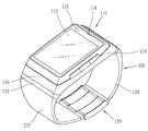
도 1은 본 발명의 일 실시예에 따르는 와치형 이동 단말기를 전면에서 바라본 사시도이다.1 is a perspective view of a watch-type mobile terminal according to an exemplary embodiment of the present invention.
도 1을 참조하면, 와치형 이동 단말기는 본체(110)와, 본체(110)의 양측에 연결되는 밴드(120)를 포함한다.1, a watch-type mobile terminal includes a
본체(110)은 무선통신 모듈(181, 도 7 참조)을 구비하여 이동통신 기지국과 무선 신호를 송/수신하도록 형성된다.The
본체(110)의 외관을 이루는 케이스(케이싱, 하우징, 커버 등)는 합성 수지로 형성되거나, 스테인레스 스틸(STS) 또는 티타늄(Ti) 등과 같은 금속 재질을 갖도록 형성된다. 케이스 내부에 형성된 공간에는 각종 전자부품들이 내장된다.The case (casing, housing, cover, etc.) constituting the external appearance of the
케이스는 프론트 케이스(111)와 리어 케이스(112)에 의하여 형성될 수 있다. 아울러, 프론트 케이스(111)와 리어 케이스(112) 사이에는 적어도 하나의 중간 케이스들이 추가로 배치될 수도 있다.The case may be formed by the
프론트 케이스(111)와 리어 케이스(111)는 합성 수지를 사출하여 형성되거나, 스테인레스 스틸 등의 금속 재질로 형성될 수 있다. 프론트 케이스(111)와 리어 케이스(112)는 각종 전자부품이 내장되는 내부 공간을 형성한다.The
밴드(120)는 사용자의 손목이나 팔 등에 착용할 수 있도록 형성된다. 밴드(150)는 가죽(leather) 또는 고무(rubber)나 플라스틱(plastics), 또는 금속 재질로 형성될 수 있으며, 여러 개의 단일층이 적층되어 다층 형태로 구성될 수 있다.The
밴드(120)는 본체(110)의 일단에 연결되는 제1밴드(121)와, 본체(110)의 타단에 연결되는 제2밴드(122)를 포함할 수 있다.The
밴드(120), 즉 제1밴드(121)와 제2밴드(122)의 사이에는 밴드(120)를 사용자의 손목이나 팔 등에 착탈시키는 버클유닛(130,buckle unit)이 장착된다. 버클유닛(130)은 접속 및 접속해제 동작에 의해 밴드(120, 또는 이동 단말기)를 사용자의 손목에 장착 또는 분리시킨다.Between the
버클유닛(130)은 제1밴드(121)와 제2밴드(122) 사이를 조이거나 조임을 해제시킬 수 있게 구성되거나, 제1밴드의 단부와 제2밴드의 단부를 체결 또는 해체시킬 수 있도록 구성된다.The
본체(110)에는 디스플레이부(113), 음향 출력부(114), 영상 입력부(115) 또는 사용자 입력부(116)가 배치될 수 있다.The
디스플레이부(113)는 프론트 케이스(111)의 주면의 대부분을 차지한다. 디스플레이부(113)는 액정 디스플레이(liquid crystal display), 박막 트랜지스터 액정 디스플레이(thin film transistor-liquid crystal display), 유기 발광 다이오드(organic light-emitting diode), 플렉시블 디스플레이(flexible display), 3차원 디스플레이(3D display) 등을 포함할 수 있다.The
디스플레이부(113)는 터치 센서를 더 포함하여 사용자의 터치에 의한 정보의 입력을 받을 수 있도록 형성될 수 있다. 터치 센서는 터치 입력 위치 및 면적 뿐만 아니라 터치 입력 압력까지도 검출할 수 있도록 구성될 수 있다. 터치 센서가 장착된 디스플레이부(113)는 터치 스크린을 형성한다.The
음향 출력부(114)는 리시버(Receiver) 또는 라우드 스피커(loud speaker)등을 포함할 수 있다.The
영상 입력부(115)는 사용자 등에 대한 이미지 또는 동영상을 촬영하기 위한 카메라 모듈과 같은 형태로 구현될 수 있다.The
사용자 입력부(116)는 와치형 이동 단말기의 동작을 제어하기 위한 명령을 입력받기 위해 조작되는 장치를 말한다. 예를 들어, 사용자 입력부(116)는 사용자의 푸시 또는 터치 조작에 의해 명령 또는 정보를 입력받을 수 있는 돔 스위치 또는 터치 스크린으로 구현되거나, 키를 회전시키는 휠 또는 조그 방식이나 조이스틱과 같이 조작하는 방식 등으로도 구현될 수 있다.The
도 2는 도 1의 와치형 이동 단말기의 후면 사시도이다.2 is a rear perspective view of the watch-type mobile terminal of FIG.
리어 케이스(112)에는 분리 가능한 커버(112a)와 접속단자(118)가 장착될 수 있다.A
커버(112a)는 합성수지를 사출하여 형성되거나 금속 재질, 예를 들어 스테인레스 스틸(STS) 또는 티타늄(Ti) 등과 같은 금속 재질을 갖도록 형성될 수 있다. 커버(112a)는 내부 부품의 수리시 분리할 수 있도록 리어 케이스(112)의 중앙 영역에 장착될 수 있다.The
접속단자(118)들은 외부 충전 장치 또는 데이터 송수신 장치에 접속하여 단말기 본체(110)에 전원을 공급하거나 데이터를 송수신하기 위한 통로가 된다.The
도 3은 본 발명의 일 실시예와 관련된 버클유닛의 구성을 나타내는 사시도이다.3 is a perspective view showing a configuration of a buckle unit according to an embodiment of the present invention.
버클유닛(130)은 서로 체결 가능하게 구성되는 '제1버클부'와 '제2버클부'를 포함한다. 제1 및 제2버클부는 제1 및 제2밴드(121,122)에 각각 연결되고 체결부에 의해 서로 체결 또는 분리 가능한 형태라면 어떠한 형태로든 구현 가능하다.The
본 실시예에 의하면, '제1버클부'는 각종 부품이 장착되는 내부 공간을 구비한 형태로 구현되며, 이는 버클 본체(131)로 불릴 수 있다. 그리고, '제2버클부'는 제2밴드에서 연장되는 형태를 플레이트의 형태를 가지며, 이는 체결 플레이트(132)로 불릴 수 있다.According to the present embodiment, the 'first buckle portion' is realized in a form having an internal space in which various components are mounted, which may be referred to as a
버클 본체(131)는 그 일단이 제1밴드(121)에 연결되며, 체결 플레이트(132)는 그 일단이 제2밴드(122)에 연결된다. 버클 본체(131)와 체결 플레이트(132)에는 연결부재(139)가 연결될 수 있으며, 연결부재(139)는 버클 본체(131)와 체결 플레이트(132)에 회전 가능하게 연결된다.One end of the buckle
버클 본체(131)와 체결 플레이트(132)는 서로 체결 또는 분리 가능하게 구성된다. 이를 위하여, 버클 본체(131)과 체결 플레이트(132)의 사이에는 이들을 체결또는 분리시키는 체결부가 구비될 수 있다.The
본 실시예는 체결부의 일 예로서, 체결 플레이트(132)에 형성되는 돌기(134)와, 버클 본체(131)의 내부에 장착된 락커(Locker,미도시)를 예시하고 있다. 체결부는 돌기(134)가 락커에 구속되는 형태로 구현될 수 있으며, 이러한 경우 락커는 버클 본체(131)의 언록킹 버튼(135)이 누름 동작됨에 따라 돌기(134)의 구속을 해제시키도록 구성된다.The present embodiment is an example of a fastening portion and shows a
버클 본체(131)의 내부에는 각종 전자부품이 장착될 수 있으며, 이들은 연성회로기판(136)에 의해 본체(110)와 전기적으로 연결된다. 제1밴드(121)에는 연성회로기판(136)을 관통시키기 위한 관통홀(137)이 형성된다.Various electronic components can be mounted inside the buckle
본 실시예는 제1버클부(131, 버클 본체)에만 전자부품들이 장착되는 구조를 예시하고 있으나, 제1 및 제2버클부 모두에 전자부품들이 장착되는 것도 가능하다 할 것이다. 이러한 경우, 제1 및 제2버클부에 두 개의 연성회로기판들이 각각 연결되어 이들이 제1 및 제2밴드(121,122)를 통해 본체(110)에 연결되는 구조를 가질 것이다.Although the present embodiment illustrates a structure in which electronic components are mounted only on the first buckle portion 131 (buckle body), electronic components may be mounted on both the first and second buckle portions. In this case, the two flexible circuit boards are connected to the first and second buckle portions, respectively, so that they are connected to the
도 4a 및 4b는 본 발명의 제1실시예와 관련된 버클 유닛의 단면도들이다.4A and 4B are cross-sectional views of a buckle unit according to a first embodiment of the present invention.
도 4a는 버클 본체(131, 제1버클부)와 체결 플레이트(132, 제2버클부)가 체결된 '접속 상태'를 나타내고 있으며, 도 4b는 버클 본체(131)와 체결 플레이트(132)가 분리된 '접속해제 상태'를 나타내고 있다.4A shows a 'connected state' in which the
버클유닛(130)은 버클유닛(130)의 접속시 본체(110)의 전원을 온(ON) 시키기 위한 신호를 발생시키는 신호 발생부(140)를 포함한다. 신호 발생부(140)와 본체(110)는 전기적으로 연결되며, 이들은 연성회로기판(136)에 의해 연결될 수 있다.The
신호 발생부(140)는 버클유닛(130)이 접속해제 상태에서 접속상태로 전환되면, 본체(110)의 전원을 온(ON)시키기 위한 신호를 본체(110)에 전달하며, 이에 의해 본체(110)는 전원 오프(OFF) 상태에서 전원 온(ON) 상태로 전환되게 된다.The
한편, 신호 발생부(140)는 버클유닛(130)의 접속이 해제되었을 때, 즉, 버클본체(131)와 체결 플레이트(132)가 분리되었을 때 본체(110)의 전원을 오프(OFF)시키도록 구성되는 것도 가능하다.The
도 4a와 같이, 신호 발생부(140)는 버클 본체(131)에 장착되는 스위치(140)의 형태로 구현될 수 있다. 스위치(140)는 버클 본체(131)의 배면에 누름 동작 가능하게 장착되며, 누름 동작에 의해 본체(110)의 전원을 온(ON)시키기 위한 신호를 발생시키도록 구성된다.4A, the
도 4b와 같이, 스위치(140)는 버클 본체(131)와 체결 플레이트(132)가 체결됨에 따라 체결 플레이트(132) 또는 연결부재(139)와 접촉되어 누름 동작되게 되며, 이에 따라 스위치(140)는 본체(110)의 전원을 온(ON)시키기 위한 신호를 발생시키게 된다.The
도 4c는 신호 발생부의 동작에 따른 와치형 이동 단말기의 작동 상태를 나타내고 있다. 스위치(140)에서 발생된 신호는 본체(110)에 전달되게 되며, 본체(110) 는 전원 오프(OFF) 상태에서 전원 온(ON) 상태로 전환되게 된다. 이러한 경우, 본체(110)의 디스플레이부(113)은 기 설정된 시각 정보를 출력하게 된다. 본 도면에서는 현재의 시각을 나타내는 시계 형태의 그래픽이 출력된 것을 예시하고 있다.4C shows an operating state of the watch-type mobile terminal according to the operation of the signal generator. The signal generated from the
이상에서는 신호 발생부(140)가 제1버클부(131, 버클 본체)에 장착되는 것을 예시하였지만, 신호 발생부(140)는 제1 및 제2버클부(131,132) 양 쪽에 위치하거나 이들 중 어느 하나에 위치하는 것도 가능하다 할 것이다.The
도 5는 본 발명의 제2실시예와 관련된 버클 유닛의 단면도들이다.5 is a cross-sectional view of a buckle unit according to a second embodiment of the present invention.
본 실시예와 관련된 버클유닛(230)은 앞선 실시예의 체결부(133)와 신호 발생부(140)를 제외하고 앞선 실시예와 동일한 구성을 갖는다. 본 도면에서는 앞선 실시예와 동일, 유사한 구성에 대해서 유사한 도면 부호를 부여하였다.The
본 실시예에 따르면, 체결부(233)는 제1 및 제2버클부(231,232)에 각각 장착되는 한 쌍의 자석들(234,235)의 형태로 구현된다. 버클 본체(231, 제1버클부)의 내부에는 제1자석(234)가 배치되고, 체결 플레이트(232, 제2버클부)의 전면에는 제2자석(235)가 배치된다. 제1 및 제2자석(234,235)은 서로 마주하는 면이 서로 반대 극성을 갖도록 배치된다.According to the present embodiment, the
버클 본체(231)와 체결 플레이트(232)가 중첩됨에 따라, 제2자석(235)이 버클 본체(231)의 체결홈(238)에 삽입되게 된다. 이 때, 제2자석(235)은 체결홈(238)의 일측에 위치한 제1자석(234)과의 인력에 의해 체결홈(238)에 부착되게 된다.The
신호 발생부는 자석들 중 적어도 하나에서 발생하는 자기장의 세기를 감지하는 자기 센서(240)의 형태로 구현된다. 자기 센서(240)는 제1자석(234)과 제2자 석(235) 사이에 발생하는 자기장 세기의 변화를 통해 버클유닛(230)의 접속 여부를 감지한다. 버클유닛(230)이 접속 상태로 전환되면, 자기 센서는 신호를 발생시켜 이를 본체(110)로 전달한다.The signal generator is implemented in the form of a
이상에서는 스위치(140)와 자기 센서(240)를 '신호 발생부'의 예로서 들었으나, 신호 발생부는 제1버클부(131,231)와 제2버클부(132,232)의 체결 여부, 즉 버클유닛(130,230)의 접속 여부를 감지하여 신호를 발생시킬 수 있는 구성이라면 어떠한 형태로든 구현 가능하다 할 것이다. 예를 들어, 신호 발생부는 제1버클부(131,231)와 제2버클부(132,232)의 사이의 접촉을 감지하는 접촉 센서의 형태로 구현될 수도 있다. 이러한 경우, 접촉 센서는 제1버클부(131,231)와 제2버클부(132,232) 중 어느 하나에 장착되어 다른 하나와 접촉되며, 그와의 접촉에 따라 신호를 발생시키게 된다.Although the
도 6은 본 발명의 제3실시예와 관련된 버클유닛의 평면도이며, 도 7은 도 6에 도시된 버클유닛의 내부 구조를 보인 단면도이다. 본 도면들에서는 앞선 실시예들과 동일, 유사한 구성들에 대해서 유사한 도면 부호를 부여하였다.FIG. 6 is a plan view of a buckle unit according to a third embodiment of the present invention, and FIG. 7 is a sectional view showing the internal structure of the buckle unit shown in FIG. In the drawings, the same reference numerals are given to the same and similar components as the previous embodiments.
도 6을 참조하면, 본 실시예와 관련된 버클유닛(330)은 사용자의 조작에 의해 본체(110)에 정보를 입력하는 적어도 하나의 조작유닛(350,360)을 구비한다.Referring to FIG. 6, the
본 실시예에 의하면, 조작유닛(350,360)은 버클 본체(331)의 양 측면에 장착되는 제1조작유닛(350)과 제2조작유닛(360)을 포함한다. 본 실시예는 조작유닛들(350,360)이 제1버클부(351, 버클 본체)에 장착되는 것을 예시하고 있으나, 조작유닛들(350,360)은 '제2버클부'에 장착되거나 '제1 및 제2버클부'에 모두 장착되는 것도 가능하다 할 것이다.The
도 7을 참조하면, 이러한 조작유닛들(350,360)은 버클유닛(330), 구체적으로 버클 본체(331)의 측면에 누름 동작 가능하게 장착되는 키버튼(351,361)과, 키버튼(351,361)이 누름 동작됨에 따라 신호를 발생시키는 스위치(352,362)를 포함한다.7, the
스위치(352,362)는 버클 본체(331) 내부의 기판(353,363) 상에 장착되며, 누름 동작된 키버튼(351,361)에 의해 눌려짐에 따라 변형되게 된다. 이에 따라 기판(353,363) 상에 형성된 접접들이 연결되어 신호가 발생하게 된다.The
버클 본체(331)의 내부에는 메인 보드(338)가 장착될 수 있으며, 메인 보드(338)와 스위치(352,362)가 형성된 기판들(353,363)은 연성회로기판(336)에 의해 본체(110)와 전기적으로 연결된다.The
조작유닛(350,360)은 본체(110)에 다양한 종류의 명령을 입력하도록 설정될 수 있다. 이러한 명령들의 일 예로서, 본체(100) 전원을 온/오프 시키기 위한 명령, 통화를 위한 통화 명령(또는, 호 연결 명령), 기 입력된 명령을 취소하기 위한 취소 명령, 커서 또는 포인터의 이동 명령, 음향 또는 그래픽의 상태량(예를 들어, 음량)을 조절 하기 위한 조절 명령 등을 들 수 있을 것이다.The
본 실시예와 관련된 버클유닛(330)에는 앞선 실시예에서 설명한 구성들, 즉, 버클유닛(130,230)이 접속되면 본체(110)의 전원을 온(ON) 시키는 구성들이 적용되는 것도 가능하다 할 것이다. 이러한 경우, 앞선 실시예들의 스위치(140), 자기센서(240) 등은 메인 보드(338) 상에 장착될 수 있다.It is also possible to apply the configurations described in the previous embodiments, that is, the configurations in which the power source of the
도 8은 도 6의 조작유닛들의 작동 상태의 일 예를 나타내는 이동 단말기의 정면도들이다. 도 8은 와치형 이동 단말기를 이용하여 전화를 거는 것을 예시하고 있다.8 is a front view of the mobile terminal showing an example of the operating states of the operation units of Fig. FIG. 8 exemplifies a telephone call using the watch-type mobile terminal.
디스플레이부(151)가 터치스크린의 형태로 구현된 경우, 디스플레이부(151)에는 전화 번호를 입력할 수 있도록 숫자가 표시된 소프트키(113a)들이 표시된다. 이 때, 소프트키(151a)가 터치되면, 터치된 소프트키(151a)에 대응되는 숫자가 출력창(151b)에 표시된다.When the display unit 151 is implemented in the form of a touch screen, the display unit 151 displays
본 실시예에 의하면, 제1조작유닛(350)은 호 연결 명령(또는. 센드 명령)을 수행하도록 설정되고, 제2조작유닛(360)이 기수행된 명령의 취소를 위한 최소 명령을 수행하도록 설정되어 있다According to the present embodiment, the
소프트키(151)가 터치됨에 따라 통화하고자 하는 전화번호가 입력된 후, 제1조작유닛(350)이 조작되면 출력창(151b)에 표시된 전화번호에 대한 호 연결이 시도된다.When the
아울러, 전화번호가 오입력되었을 경우, 제2조작유닛(360)이 조작되면 기 입력된 내용을 취소할 수도 있다. 본 도면은 제2조작유닛(360)의 조작에 의해 기 입력된 숫자 '9'가 지워진 것을 나타내고 있다.In addition, when the telephone number is erroneously input, the
도 9은 도 6의 조작유닛들의 작동 상태의 다른 예를 나타내는 이동 단말기의 정면도들이다.9 is a front view of the mobile terminal showing another example of the operating states of the operating units of Fig.
조작유닛(350,360)은 본체(110)에 기설정된 작동 모드의 실행 명령을 입력하도록 구성될 수 있다. 이러한 작동 모드는 대기 모드, 메뉴 표시 모드, 전화 모드, 및 문자 메시지 송수신 모드 등 다양한 종류의 작동 모드 중 적어도 하나를 포함할 수 있다.The
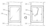
본 실시예는 제1조작유닛(350)이 전화 모드의 실행 명령을 입력하도록 설정되고, 제2조작유닛(360)이 메뉴 표시 모드의 실행 명령을 입력하도록 설정된 것을 예시하고 있다. 와치형 이동 단말기는 본 도면과 같이 대기 모드에서 현재 시각을 나타내는 그래픽을 출력하도록 설정될 수 있다.The present embodiment illustrates that the
대기 모드에서 제1조작유닛(350)이 조작되면, 전화모드가 실행되어 디스플레이부(113)에 전화 번호의 입력을 위한 소프트키(113a)들이 표시된다.When the
또한, 대기 모드에서 제2조작유닛(360)이 조작되면, 메뉴 표시 모드가 실행되어 디스플레이부(113)에 이동 단말기의 각종 기능을 나타내는 아이콘(113c)들이 표시된다. 사용자는 아이콘(113c)를 터치하여 해당 기능을 작동시킬 수 있다.Also, when the
이러한 제1 및 제2조작유닛(350,360)에 할당되는 명령은 미리 설정되어 있는것도 가능하지만, 사용자에 의해 선택될 수 있도록 구성되는 것도 가능하다 할 것이다. 이러한 경우, 사용자는 자주 사용하는 명령을 제1 및 제2조작유닛(350,360)에 할당할 수 있을 것이다.The commands to be assigned to the first and
도 10은 본 발명의 제4실시예와 관련된 버클유닛의 측면도이며, 도 11은 도 10의 버클 유닛의 평면도들이다. 본 도면들에서는 앞선 실시예들과 동일, 유사한 구성들에 대해서 유사한 도면 부호를 부여하였다.10 is a side view of the buckle unit according to the fourth embodiment of the present invention, and Fig. 11 is a plan view of the buckle unit of Fig. In the drawings, the same reference numerals are given to the same and similar components as the previous embodiments.
본 실시예와 관련된 버클유닛(430)은 조작 유닛(350,360)을 제외하고 제3실시예의 버클유닛(330)과 동일한 구성을 갖는다. 본 실시예의 조작유닛(450)은 버클 유닛(430), 구체적으로 버클 본체(431)의 외면에 슬라이드 가능하게 장착되는 슬라이더(451)를 포함한다. 와치형 이동 단말기가 손목에 착용된 경우, 슬라이더(451)는 버클유닛(430)의 바깥쪽에 장착된다.The
조작유닛(450)은 슬라이더(451)가 적어도 일방향으로 슬라이드됨에 따라 본체(110)에 명령을 입력하기 위한 신호를 발생시킨다.The
도 10 및 11과 같이, 본 실시예에 의한 조작유닛(450)은 슬라이더(451)가 양 방향으로 이동될 수 있도록 구성된다. 슬라이더(451)가 일 방향으로 이동하는 경우 조작유닛(450)은 본체(110)에 기설정된 특정 명령을 입력하고, 슬라이더(451)가 다른 방향으로 이동하는 경우 조작유닛(450)은 기설정된 다른 명령을 입력한다.10 and 11, the
슬라이더(451)가 서로 다른 방향으로 이동됨에 따라 본체에 각각 입력되는 명령들은 앞선 실시예의 제1 및 제2조작유닛(350,360)에 할당되는 명령들과 대응되게 설정될 수 있다.As the
예를 들어, 슬라이더(451)가 도 11의 왼쪽으로 이동하는 경우 조작유닛(450)은 본체(110)에 호 연결 명령을 입력하고, 슬라이더가 도 11의 오른쪽으로 이동하는 경우 조작유닛(450)은 본체(110)에 기입력된 명령을 취소하는 명령을 입력하도록 설정될 수 있다.For example, when the
참고로, 도 10 및 11에서는 슬라이더(451)가 좌우 방향으로 이동하는 것을 도시하고 있지만, 와치형 이동 단말기를 손목에 착용한 경우 슬라이더(451)는 도 1의 도시를 기준으로 상하 방향으로 이동하게 될 것이다.10 and 11 illustrate that the
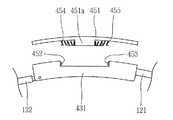
도 12a는 슬라이더를 버클유닛으로부터 분리한 도면이며, 도 12b는 도 10에 도시된 버클유닛의 단면도이다.FIG. 12A is a view showing the slider separated from the buckle unit, and FIG. 12B is a sectional view of the buckle unit shown in FIG.
슬라이더(451)의 배면에는 슬라이드부(451a)가 형성되며, 슬라이드부(451a)는 버클 본체(431)에 슬라이드 가능하게 장착된다.A
버클 본체(431)의 측벽에는 슬라이더(451)의 슬라이드 이동에 따라 신호를 발생시키는 스위치(452,453)가 장착된다. 스위치(452,453)는 버클 본체(431)의 양 측벽에 각각 장착되는 제1 및 제2스위치(452,453)를 포함할 수 있다. 제1 및 제2스위치(452,453)는 슬라이더(451)의 슬라이드 이동에 따라 슬라이더(451)의 양단에 접촉되도록 배치된다.On the side wall of the buckle
제1스위치(452)는 슬라이더(451)가 일방향으로 이동함에 따라 슬라이드부(451a)에 의해 누름 동작되어 신호를 발생시키며, 제2스위치(453)는 슬라이더(451)가 다른 방향으로 이동함에 따라 슬라이드부(451a)에 의해 누름 동작되어 신호를 발생시킨다.The
본 실시예의 제1 및 제2스위치(452,453)는 슬라이더(451)의 이동을 감지하여 신호를 발생시키는 구성이라면 다양한 형태로 변형 실시될 수 있을 것이다.The first and
슬라이드부(451)의 양단과 버클 본체(431)의 측벽들 사이에는 복귀 스프링(454,455)가 장착되며, 이들은 슬라이더(451)의 이동시 슬라이더(451)를 원위치로 복귀시킨다.Return springs 454 and 455 are mounted between the opposite ends of the
도 13은 도 10에 도시된 조작유닛의 작동 상태의 일 예를 나타내는 사시도들이다.13 is a perspective view showing an example of the operating state of the operating unit shown in Fig.
제1 및 제2스위치(452,453)는 디스플레이부(113)에 표시된 커서, 포인터, 그 래픽, 및 아이콘 중 적어도 하나를 슬라이더의 이동 방향으로 이동시키기 위한 신호를 발생시킬 수 있다.The first and
본 도면은 디스플레이부(113)에 전화 번호부가 출력된 것을 예시하고 있으며, 전화 번호부는 복수의 항목이 리스트의 형태로 구현될 수 있다.This figure illustrates the output of the phone book on the
이와 같은 항목들 중 하나에는 포인터(113e)가 위치할 수 있으며, 사용자는 포인터(113e)가 위치한 항목을 선택하여 해당 항목의 전화번호가 출력되도록 할 수 있다.The
이 때, 슬라이더(451)가 상측으로 이동하면 포인터(113e)가 현재 항목에서 상측에 위치한 항목으로 이동하게 된다. 또한, 슬라이더(451)가 하측으로 이동하면 포인터(113e)가 현재 항목에서 하측에 위치한 항목으로 이동하게 된다. 즉, 버클유닛(430)에 장착된 슬라이더(451)는 본체에 스크롤 입력을 가능하게 한다.At this time, when the
도 14는 도 10에 도시된 조작유닛의 작동 상태의 다른 예를 나타내는 사시도들이다.Fig. 14 is a perspective view showing another example of the operating state of the operating unit shown in Fig. 10; Fig.
본 도면은 슬라이더(451)를 이용하여 디스플레이부(113)에 표시된 그래픽 또는 아이콘을 이동시키는 것을 나타내고 있다.This drawing shows that the graphic or icon displayed on the
디스플레이부(113)에는 메모리에 저장된 사진들을 축소시켜 나타낸 복수의 그래픽(113f, 또는 아이콘)들이 표시되어 있다. 현재 선택된 그래픽(113f)은 화면 중앙에 크게 표시되고, 선택된 그래픽의 전후 순서에 있는 그래픽들(113g,113h)은 그의 상측과 하측에 작게 표시된다.A plurality of
슬라이더(451)가 상측으로 이동하면 현재 선택된 그래픽(113f)의 하측에 위 치한 그래픽(113h)이 상측으로 이동하여 크게 표시된다. 그리고, 슬라이더(451)가 하측으로 이동하면 현재 선택된 그래픽(113f)의 상측에 위치한 그래픽(113h)이 하측으로 이동하여 크게 표시된다.When the
도 15는 본 발명에 관련된 와치형 이동 단말기의 블록 구성도(block diagram)이다.15 is a block diagram of a watch-type mobile terminal according to the present invention.
도 15를 참조하면, 본 발명의 일 실시예에 따른 와치형 이동 단말기는 디스플레이부(113), 음향 출력부(114), 영상 입력부(115), 사용자 입력부(116), 전원공급부(189), 제어부(180), 무선통신 모듈(181), 메모리(184), 방송수신 모듈(185), 센싱유닛(186), 음향 입력부(187), 인터페이스(188)를 포함한다.15, a watch mobile terminal according to an exemplary embodiment of the present invention includes a
제어부(180)는 통상적으로 와치형 이동 단말기의 전반적인 동작을 제어한다. 예를 들어 음성 통화, 데이터 통신, 화상 통화 등을 위한 관련된 제어 및 처리를 수행한다.The
무선통신 모듈(181)은 안테나를 통하여 이동통신 기지국과 무선 신호를 송/수신한다. 예를 들어 제어부(160)의 제어 하에 음성 데이터, 문자 데이터, 영상 데이터 및 제어 데이터의 송수신을 담당하며 이를 위해 송신할 신호를 변조하여 송신하는 송신부(162)와, 수신되는 신호를 복조하는 수신부(183)을 포함한다.The
사용자 입력부(116)는 사용자가 단말기의 동작 제어를 위하여 입력하는 키 입력 데이터를 제어부(180)에 제공한다. 사용자 입력부(116)는 돔 스위치(dome switch), 터치 패드(정압/정전), 조그 휠, 조그 스위치 등으로 구성된다.The
영상 입력부(115)는 화상 통화모드 또는 촬영 모드에서 이미지 센서에 의해 얻어지는 정지영상 또는 동영상 등의 화상 프레임을 처리한다. 그리고, 처리된 화상 프레임은 디스플레이부(113)에 표시 가능한 영상 데이터로 변환되어 디스플레이부(113)로 출력된다.The
영상 입력부(115)에서 처리된 화상 프레임은 제어부(180)의 제어에 의해 메모리(184)에 저장되거나 무선통신 모듈(181)를 통하여 외부로 전송된다.The image frame processed by the
음향 입력부(117)는 통화모드 또는 녹음모드, 음성인식 모드 등에서 마이크로폰(Microphone)에 의해 외부의 음향 신호를 입력받아 전기적인 음성 데이터로 처리한다. 그리고, 처리된 음성 데이터는 통화 모드인 경우 무선통신 모듈(181)를 통하여 이동통신 기지국으로 송신 가능한 형태로 변환되어 무선통신 모듈(181)로 출력된다. 녹음 모드인 경우 처리된 음성 데이터는 메모리(184)에 저장되도록 출력된다.The
음향 입력부(117)는 외부의 음향 신호를 입력받는 과정에서 발생되는 잡음(noise)를 제거하기 위한 다양한 잡음 제거 알고리즘이 구현될 수 있다.The
디스플레이부(113)는 와치형 이동 단말기에서 처리되는 정보를 표시 출력한다. 예를 들어 와치형 이동 단말기가 통화 모드인 경우 제어부(180)의 제어에 의해 통화와 관련된 UI(User Interface) 또는 GUI(Graphic User Interface)를 표시 출력한다. 그리고 와치형 이동 단말기가 화상 통화 모드 또는 촬영 모드인 경우 제어부(180)의 제어에 의해 촬영된 영상 또는 UI, 및 GUI 등을 표시 출력한다. 디스플레이부(113)는 터치 스크린을 포함하여 구성되는 경우, 출력 장치 이외에 입력 장치로 사용된다.The
음향 출력부(114)는 호신호 수신, 통화모드 또는 녹음 모드, 음성인식 모드, 방송수신 모드 등에서 제어부(180)의 제어에 의해 무선통신 모듈(181)로부터 수신된 음향 데이터 또는 메모리(184)에 저장된 음향 데이터를 변환하여 외부로 출력한다.The
또한, 음향 출력부(114)는 와치형 이동 단말기에서 수행되는 기능(예를 들어, 호신호 수신음, 메시지 수신음 등)과 관련된 음향 신호를 출력한다.Also, the
센싱유닛(186)은 와치형 이동 단말기의 위치, 사용자 접촉 유무, 버클 유닛(130)의 접속 유무 등과 같이 와치형 이동 단말기의 현 상태를 감지하여 와치형 이동 단말기의 동작을 제어하기 위한 센싱 신호를 발생시킨다. 또한 전원 공급부(170)의 전원 공급 여부, 인터 페이스(188)의 외부 기기 결합 여부 등과 관련된 센싱 기능을 담당한다.The
인터페이스(188)는 와치형 이동 단말기 이외 유/무선 헤드셋, 외부 충전기, 유/무선 데이터 포트, 카드 소켓(예를 들어, 메모리 카드(Memory card), SIM/UIM card) 등을 와치형 이동 단말기에 연결되는 모든 외부기기와의 인터페이스 역할을 한다. 이와 같은 인터페이스(119)는 외부 기기로부터 데이터를 전송받거나 전원을 공급받아 와치형 이동 단말기 내부의 각 구성 요소에 전달하거나 와치형 이동 단말기 내부의 데이터가 외부 기기로 전송되도록 한다.The
메모리(184)는 제어부(180)의 처리 및 제어를 위한 프로그램이 저장될 수도 있고, 입/출력되는 데이터들(예를 들어, 폰북, 메시지, 정지영상, 동영상 등)의 임시 저장을 위한 기능을 수행할 수도 있다.The
또한, 메모리(184)에는 본 발명과 관련된 와치형 이동 단말기의 동작을 제어하는 프로그램이 저장된다 이러한 메모리(184)는 일반적으로 알려진 하드 디스크, 카드 타입의 메모리(예를 들어 SD 또는 XD 메모리 등), 플래시 메모리, 램, 롬 등의 개념을 포함한다.The
방송수신 모듈(185)은 위성 또는 지상파 등을 통하여 전송된 방송 신호를 수신하여 음향 출력부(114), 디스플레이부(113)에 출력 가능한 방송 데이터 형태로 변환하여 제어부(180)에 출력한다. 또한 방송수신 모듈(185)은 방송과 관련된 부가 데이터(예를 들면, EPG(Electric Program Guide), 채널 리스트 등)를 수신한다. 방송수신 모듈(185)에서 변환된 방송 데이터 및 부가 데이터는 메모리(184)에 저장될 수도 있다.The
전원 공급부(189)는 제어부(180)의 제어에 의해 외부의 전원, 내부의 전원을 인가받아 각 구성요소들의 동작에 필요한 전원을 공급한다.The
상기와 같은 와치형 이동 단말기는 위에서 설명된 실시예들의 구성과 방법에 한정되는 것이 아니라, 상기 실시예들은 다양한 변형이 이루어질 수 있도록 각 실시예들의 전부 또는 일부가 선택적으로 조합되어 구성될 수도 있다.The above-described watch mobile terminal is not limited to the configuration and method of the embodiments described above, but all or some of the embodiments may be selectively combined so that various modifications may be made to the embodiments.
도 1은 본 발명의 일 실시예에 관련된 휴대 단말기의 전면 사시도.1 is a front perspective view of a mobile terminal according to an embodiment of the present invention;
도 2는 본 발명의 일 실시예에 관련된 휴대 단말기의 후면 사시도.2 is a rear perspective view of a portable terminal according to an embodiment of the present invention;
도 3은 본 발명의 일 실시예와 관련된 버클유닛의 구성을 나타내는 사시도.3 is a perspective view showing a configuration of a buckle unit according to an embodiment of the present invention;
도 4a 및 4b는 본 발명의 제1실시예와 관련된 버클 유닛의 단면도들.4A and 4B are cross-sectional views of a buckle unit in accordance with a first embodiment of the present invention.
도 4c는 신호 발생부의 동작에 따른 와치형 이동 단말기의 작동 상태를 나타내는 정면도.4C is a front view showing an operation state of the watch-type mobile terminal according to the operation of the signal generator;
도 5는 본 발명의 제2실시예와 관련된 버클 유닛의 단면도들.5 is a cross-sectional view of a buckle unit in accordance with a second embodiment of the present invention.
도 6은 본 발명의 제3실시예와 관련된 버클유닛의 평면도.6 is a plan view of a buckle unit according to a third embodiment of the present invention;
도 7은 도 6에 도시된 버클유닛의 내부 구조를 보인 단면도.7 is a sectional view showing the internal structure of the buckle unit shown in Fig. 6;
도 8은 도 6의 조작유닛들의 작동 상태의 일 예를 나타내는 이동 단말기의 정면도들.8 is a front view of the mobile terminal showing an example of the operating state of the operating units of Fig.
도 9은 도 6의 조작유닛들의 작동 상태의 다른 예를 나타내는 이동 단말기의 정면도들.9 is a front view of the mobile terminal showing another example of the operating states of the operating units of Fig.
도 10은 본 발명의 제4실시예와 관련된 버클유닛의 측면도.10 is a side view of a buckle unit according to a fourth embodiment of the present invention.
도 11은 도 10의 버클 유닛의 평면도들.11 is a plan view of the buckle unit of Fig.
도 12a는 슬라이더를 버클유닛으로부터 분리한 도면.12A is a view showing the slider separated from the buckle unit;
도 12b는 도 10에 도시된 버클유닛의 단면도.FIG. 12B is a sectional view of the buckle unit shown in FIG. 10; FIG.
도 13은 도 10의 조작유닛의 작동 상태의 일 예를 나타내는 사시도들.13 is a perspective view showing an example of the operating state of the operating unit of Fig.
도 14는 도 10의 조작유닛의 작동 상태의 다른 예를 나타내는 사시도들.14 is a perspective view showing another example of the operating state of the operating unit of Fig.
도 15은 본 발명의 일 실시예에 관련된 휴대 단말기의 블록 구성도.15 is a block diagram of a mobile terminal according to an embodiment of the present invention.
Claims (20)
Translated fromKoreanPriority Applications (2)
| Application Number | Priority Date | Filing Date | Title |
|---|---|---|---|
| KR1020090066028AKR101595384B1 (en) | 2009-07-20 | 2009-07-20 | Watch type mobile terminal |
| US12/819,765US8301211B2 (en) | 2009-07-20 | 2010-06-21 | Watch type mobile terminal |
Applications Claiming Priority (1)
| Application Number | Priority Date | Filing Date | Title |
|---|---|---|---|
| KR1020090066028AKR101595384B1 (en) | 2009-07-20 | 2009-07-20 | Watch type mobile terminal |
Publications (2)
| Publication Number | Publication Date |
|---|---|
| KR20110008607A KR20110008607A (en) | 2011-01-27 |
| KR101595384B1true KR101595384B1 (en) | 2016-02-18 |
Family
ID=43465676
Family Applications (1)
| Application Number | Title | Priority Date | Filing Date |
|---|---|---|---|
| KR1020090066028AExpired - Fee RelatedKR101595384B1 (en) | 2009-07-20 | 2009-07-20 | Watch type mobile terminal |
Country Status (2)
| Country | Link |
|---|---|
| US (1) | US8301211B2 (en) |
| KR (1) | KR101595384B1 (en) |
Families Citing this family (89)
| Publication number | Priority date | Publication date | Assignee | Title |
|---|---|---|---|---|
| US7469381B2 (en) | 2007-01-07 | 2008-12-23 | Apple Inc. | List scrolling and document translation, scaling, and rotation on a touch-screen display |
| KR101659023B1 (en)* | 2010-03-15 | 2016-09-23 | 엘지전자 주식회사 | Watch type mobile terminal |
| EP2447790A1 (en)* | 2010-10-27 | 2012-05-02 | The Swatch Group Research and Development Ltd. | Glass for sealing the top of the housing of a portable object |
| US9152130B2 (en)* | 2011-01-19 | 2015-10-06 | Ph Technical Labs, Llc | Mobile communication watch utilizing projected directional sound |
| US8851372B2 (en)* | 2011-07-18 | 2014-10-07 | Tiger T G Zhou | Wearable personal digital device with changeable bendable battery and expandable display used as standalone electronic payment card |
| USD715674S1 (en)* | 2012-03-01 | 2014-10-21 | Blake Squires | Wristband |
| USD731898S1 (en)* | 2012-03-01 | 2015-06-16 | Movband, Llc | Wrist-worn electronic display |
| USD735587S1 (en)* | 2012-03-01 | 2015-08-04 | Movband, Llc | Wrist-worn electronic display |
| US20130271355A1 (en)* | 2012-04-13 | 2013-10-17 | Nokia Corporation | Multi-segment wearable accessory |
| KR102048921B1 (en) | 2012-06-20 | 2019-11-27 | 삼성디스플레이 주식회사 | Cell cutting device and Cell cutting method |
| USD724556S1 (en)* | 2012-11-14 | 2015-03-17 | Lg Electronics Inc. | Wireless communication device for mobile phones |
| US10691230B2 (en) | 2012-12-29 | 2020-06-23 | Apple Inc. | Crown input for a wearable electronic device |
| US10275117B2 (en)* | 2012-12-29 | 2019-04-30 | Apple Inc. | User interface object manipulations in a user interface |
| US11513675B2 (en) | 2012-12-29 | 2022-11-29 | Apple Inc. | User interface for manipulating user interface objects |
| AU351003S (en)* | 2013-02-23 | 2013-09-25 | Samsung Electronics Co Ltd | Electronic device |
| KR102171444B1 (en) | 2013-04-22 | 2020-10-29 | 엘지전자 주식회사 | Smart watch and method for controlling thereof |
| EP2796948A1 (en)* | 2013-04-23 | 2014-10-29 | ETA SA Manufacture Horlogère Suisse | Method for managing operations of an electronic device |
| USD751928S1 (en)* | 2013-05-21 | 2016-03-22 | Qualcomm Incorporated | Wrist display |
| WO2015003475A1 (en)* | 2013-07-12 | 2015-01-15 | Chen Yuanxie | Structure of wrist watch mobile phone |
| US20150098309A1 (en)* | 2013-08-15 | 2015-04-09 | I.Am.Plus, Llc | Multi-media wireless watch |
| US9568891B2 (en) | 2013-08-15 | 2017-02-14 | I.Am.Plus, Llc | Multi-media wireless watch |
| USD703069S1 (en)* | 2013-08-15 | 2014-04-22 | I.Am.Symbolic, Llc | Multi-media wireless watch |
| USD756241S1 (en)* | 2013-08-19 | 2016-05-17 | Arm Ip Limited | Watch |
| USD734327S1 (en)* | 2013-08-30 | 2015-07-14 | Samsung Electronics Co., Ltd. | Electronic device |
| USD729238S1 (en)* | 2013-08-30 | 2015-05-12 | Samsung Electronics Co., Ltd. | Electronic device |
| USD735190S1 (en)* | 2013-08-30 | 2015-07-28 | Samsung Electronics Co., Ltd. | Electronic device |
| USD733706S1 (en) | 2013-08-30 | 2015-07-07 | Samsung Electronics Co., Ltd. | Electronic device |
| USD729795S1 (en)* | 2013-08-30 | 2015-05-19 | Samsung Electronics Co., Ltd. | Electronic device |
| USD735710S1 (en)* | 2013-08-30 | 2015-08-04 | Samsung Electronics Co., Ltd. | Electronic device |
| USD727316S1 (en)* | 2013-08-30 | 2015-04-21 | Samsung Electronics Co., Ltd. | Electronic device |
| USD734328S1 (en)* | 2013-08-30 | 2015-07-14 | Samsung Electronics Co., Ltd. | Electronic device |
| USD735191S1 (en)* | 2013-08-30 | 2015-07-28 | Samsung Electronics Co., Ltd. | Electronic device |
| KR102112305B1 (en)* | 2013-09-02 | 2020-05-18 | 삼성전자주식회사 | Wearable electronic device |
| US10503388B2 (en) | 2013-09-03 | 2019-12-10 | Apple Inc. | Crown input for a wearable electronic device |
| US10545657B2 (en) | 2013-09-03 | 2020-01-28 | Apple Inc. | User interface for manipulating user interface objects |
| US11068128B2 (en) | 2013-09-03 | 2021-07-20 | Apple Inc. | User interface object manipulations in a user interface |
| CN110795005A (en) | 2013-09-03 | 2020-02-14 | 苹果公司 | User interface for manipulating user interface objects using magnetic properties |
| US10001817B2 (en) | 2013-09-03 | 2018-06-19 | Apple Inc. | User interface for manipulating user interface objects with magnetic properties |
| US12287962B2 (en) | 2013-09-03 | 2025-04-29 | Apple Inc. | User interface for manipulating user interface objects |
| KR102111452B1 (en)* | 2013-09-03 | 2020-05-15 | 애플 인크. | User interface for manipulating user interface objects |
| KR102173726B1 (en)* | 2014-01-03 | 2020-11-03 | 삼성전자주식회사 | Terminal for wearing on the wrist |
| KR102188266B1 (en)* | 2014-01-23 | 2020-12-08 | 엘지전자 주식회사 | A smart watch, a display device and the method of controlling thereof |
| US9668367B2 (en)* | 2014-02-04 | 2017-05-30 | Microsoft Technology Licensing, Llc | Wearable computing systems |
| JP1526347S (en)* | 2014-02-19 | 2018-06-04 | ||
| JP1535486S (en)* | 2014-02-19 | 2018-10-01 | ||
| KR102356925B1 (en)* | 2014-02-21 | 2022-01-28 | 삼성전자주식회사 | Electronic apparatus and power saving method thereof |
| US9239648B2 (en)* | 2014-03-17 | 2016-01-19 | Google Inc. | Determining user handedness and orientation using a touchscreen device |
| KR102244856B1 (en)* | 2014-04-22 | 2021-04-27 | 삼성전자 주식회사 | Method for providing user interaction with wearable device and wearable device implenenting thereof |
| USD746702S1 (en)* | 2014-05-08 | 2016-01-05 | Timex Group Usa, Inc. | Watch casing and a portion of a strap |
| KR101613957B1 (en) | 2014-05-19 | 2016-04-20 | 엘지전자 주식회사 | Watch type mobile terminal and control method for the mobile terminal |
| USD756242S1 (en)* | 2014-05-23 | 2016-05-17 | Arm Ip Limited | Digital watch |
| US20150335183A1 (en)* | 2014-05-26 | 2015-11-26 | Suhasini Balachandran | Smart Container |
| USD757721S1 (en)* | 2014-05-30 | 2016-05-31 | Microsoft Corporation | Portion of a wearable electronic band |
| US9152129B2 (en)* | 2014-06-25 | 2015-10-06 | Dilshan Thilina Modaragamage | Electronic watch clasp systems and methods |
| EP3147747A1 (en) | 2014-06-27 | 2017-03-29 | Apple Inc. | Manipulation of calendar application in device with touch screen |
| KR20160025830A (en)* | 2014-08-28 | 2016-03-09 | 삼성전자주식회사 | Electronic device |
| USD750040S1 (en)* | 2014-08-28 | 2016-02-23 | Steven Nohr | Audio playback system |
| TWI676127B (en) | 2014-09-02 | 2019-11-01 | 美商蘋果公司 | Method, system, electronic device and computer-readable storage medium regarding electronic mail user interface |
| CN106797493A (en) | 2014-09-02 | 2017-05-31 | 苹果公司 | Music user interface |
| CN106662966B (en) | 2014-09-02 | 2020-08-18 | 苹果公司 | Multi-dimensional object rearrangement |
| TWI582641B (en) | 2014-09-02 | 2017-05-11 | 蘋果公司 | Button functionality |
| US20160062571A1 (en) | 2014-09-02 | 2016-03-03 | Apple Inc. | Reduced size user interface |
| CN204599327U (en)* | 2014-09-02 | 2015-09-02 | 惠州市吉瑞科技有限公司 | A kind of electronic cigarette |
| KR20160030821A (en)* | 2014-09-11 | 2016-03-21 | 삼성전자주식회사 | Wearable device |
| US10114342B2 (en) | 2014-09-11 | 2018-10-30 | Samsung Electronics Co., Ltd. | Wearable device |
| CN105487598B (en)* | 2014-09-16 | 2020-03-24 | 联想(北京)有限公司 | Electronic equipment and information processing method |
| KR102269797B1 (en)* | 2014-10-08 | 2021-06-28 | 엘지전자 주식회사 | Wearable device |
| US9720376B2 (en) | 2014-11-18 | 2017-08-01 | Sony Corporation | Band type electronic device and substrate arrangement method |
| US10013025B2 (en)* | 2014-12-11 | 2018-07-03 | Intel Corporation | Wearable device with power state control |
| US10365807B2 (en) | 2015-03-02 | 2019-07-30 | Apple Inc. | Control of system zoom magnification using a rotatable input mechanism |
| KR101637368B1 (en) | 2015-03-10 | 2016-07-07 | 엘지전자 주식회사 | Watch type mobile terminal |
| WO2016153086A1 (en)* | 2015-03-20 | 2016-09-29 | 엘지전자 주식회사 | Electronic device and manufacturing method therefor |
| US10254795B2 (en)* | 2015-05-06 | 2019-04-09 | Flexterra, Inc. | Attachable, flexible display device with flexible tail |
| KR20160139733A (en)* | 2015-05-28 | 2016-12-07 | 엘지전자 주식회사 | Mobile terminal |
| KR101633358B1 (en)* | 2015-11-10 | 2016-07-29 | 주식회사 삼미무선정보시스템 | Wireless village broadcasting apparatus with time synchronization function |
| KR102479462B1 (en) | 2015-12-07 | 2022-12-21 | 삼성전자주식회사 | A flexable electronic device and an operating method thereof |
| USD825523S1 (en) | 2016-01-06 | 2018-08-14 | I.Am.Plus, Llc | Set of earbuds |
| USD786706S1 (en)* | 2016-02-17 | 2017-05-16 | Garmin Switzerland Gmbh | Watch with display |
| DK201670595A1 (en) | 2016-06-11 | 2018-01-22 | Apple Inc | Configuring context-specific user interfaces |
| USD815366S1 (en)* | 2016-07-18 | 2018-04-10 | Shu-Hui Kao | Racing pigeon foot ring |
| USD815367S1 (en)* | 2016-07-19 | 2018-04-10 | Shu-Hui Kao | Racing pigeon foot ring |
| KR102500141B1 (en) | 2016-08-30 | 2023-02-15 | 삼성전자주식회사 | Strap with improved fastening structure and wearable electronic device including the same |
| USD859412S1 (en)* | 2017-08-18 | 2019-09-10 | Practech, Inc. | Wearable or handheld hybrid smart barcode scanner |
| USD912666S1 (en)* | 2018-07-16 | 2021-03-09 | Remedee Labs | Smart watch |
| US11435830B2 (en) | 2018-09-11 | 2022-09-06 | Apple Inc. | Content-based tactile outputs |
| US10712824B2 (en) | 2018-09-11 | 2020-07-14 | Apple Inc. | Content-based tactile outputs |
| KR102344037B1 (en)* | 2020-11-23 | 2021-12-28 | 이재현 | Wearable device |
| US11893212B2 (en) | 2021-06-06 | 2024-02-06 | Apple Inc. | User interfaces for managing application widgets |
| US12314013B1 (en)* | 2022-02-21 | 2025-05-27 | Eric Robert Violland | Band aide device |
Family Cites Families (8)
| Publication number | Priority date | Publication date | Assignee | Title |
|---|---|---|---|---|
| US4591836A (en)* | 1985-01-16 | 1986-05-27 | Feigenblatt Jr Nathan | Battery operated panic alarm wrist watch |
| US4847818A (en)* | 1988-10-31 | 1989-07-11 | Timex Corporation | Wristwatch radiotelephone |
| WO1996035368A1 (en)* | 1995-05-12 | 1996-11-14 | Seiko Epson Corporation | Apparatus for diagnosing condition of living organism and control unit |
| GB9625157D0 (en)* | 1996-12-04 | 1997-01-22 | A E Patents Limited | Hearing enhancement system |
| US6158884A (en)* | 1998-06-26 | 2000-12-12 | Motorola, Inc. | Integrated communicative watch |
| GB0004688D0 (en)* | 2000-02-28 | 2000-04-19 | Radley Smith Philip J | Bracelet |
| US7474592B2 (en)* | 2001-12-05 | 2009-01-06 | Hewlett-Packard Development Company, L.P. | Secure operation of a versatile device based on whether an authenticated user continues to wear the versatile device after initiating its use |
| US9154616B2 (en)* | 2005-10-18 | 2015-10-06 | Oia Intellectuals, Inc. | Wearable capture and communication |
- 2009
- 2009-07-20KRKR1020090066028Apatent/KR101595384B1/ennot_activeExpired - Fee Related
- 2010
- 2010-06-21USUS12/819,765patent/US8301211B2/ennot_activeExpired - Fee Related
Also Published As
| Publication number | Publication date |
|---|---|
| US20110014956A1 (en) | 2011-01-20 |
| US8301211B2 (en) | 2012-10-30 |
| KR20110008607A (en) | 2011-01-27 |
Similar Documents
| Publication | Publication Date | Title |
|---|---|---|
| KR101595384B1 (en) | Watch type mobile terminal | |
| KR101587138B1 (en) | Mobile terminal | |
| KR101529921B1 (en) | Watch type terminal | |
| KR101587092B1 (en) | Mobile terminal | |
| KR101427264B1 (en) | Portable terminal | |
| US10491728B2 (en) | Key module and mobile terminal having same, and method of assembling key module | |
| KR101437991B1 (en) | Mobile terminal | |
| KR101463824B1 (en) | Functional extension assembly and a mobile terminal having the same | |
| KR101562585B1 (en) | Mobile terminal | |
| KR101659024B1 (en) | Mobile terminal | |
| US10804047B2 (en) | Mobile terminal | |
| KR101404743B1 (en) | Portable terminal having antenna module and antenna setting method therefor | |
| KR101578799B1 (en) | Casing and portable terminal having the same | |
| KR101721876B1 (en) | Mobile terminal | |
| US8024017B2 (en) | Slidable mobile terminal having a slide module | |
| KR101437972B1 (en) | Portable terminal | |
| KR20180085262A (en) | Mobile terminal | |
| KR101484537B1 (en) | Portable terminal | |
| KR101404753B1 (en) | Mobile terminal | |
| KR101513618B1 (en) | Portable terminal | |
| KR101607974B1 (en) | Mobile terminal | |
| KR101587090B1 (en) | Mobile terminal | |
| KR101495180B1 (en) | Display assembly and portable terminal having the same | |
| KR101622603B1 (en) | Portable terminal | |
| KR101427274B1 (en) | Mobile terminal |
Legal Events
| Date | Code | Title | Description |
|---|---|---|---|
| PA0109 | Patent application | St.27 status event code:A-0-1-A10-A12-nap-PA0109 | |
| R18-X000 | Changes to party contact information recorded | St.27 status event code:A-3-3-R10-R18-oth-X000 | |
| PG1501 | Laying open of application | St.27 status event code:A-1-1-Q10-Q12-nap-PG1501 | |
| A201 | Request for examination | ||
| PA0201 | Request for examination | St.27 status event code:A-1-2-D10-D11-exm-PA0201 | |
| E902 | Notification of reason for refusal | ||
| PE0902 | Notice of grounds for rejection | St.27 status event code:A-1-2-D10-D21-exm-PE0902 | |
| PN2301 | Change of applicant | St.27 status event code:A-3-3-R10-R13-asn-PN2301 St.27 status event code:A-3-3-R10-R11-asn-PN2301 | |
| E13-X000 | Pre-grant limitation requested | St.27 status event code:A-2-3-E10-E13-lim-X000 | |
| P11-X000 | Amendment of application requested | St.27 status event code:A-2-2-P10-P11-nap-X000 | |
| P13-X000 | Application amended | St.27 status event code:A-2-2-P10-P13-nap-X000 | |
| E701 | Decision to grant or registration of patent right | ||
| PE0701 | Decision of registration | St.27 status event code:A-1-2-D10-D22-exm-PE0701 | |
| PR0701 | Registration of establishment | St.27 status event code:A-2-4-F10-F11-exm-PR0701 | |
| PR1002 | Payment of registration fee | St.27 status event code:A-2-2-U10-U11-oth-PR1002 Fee payment year number:1 | |
| PG1601 | Publication of registration | St.27 status event code:A-4-4-Q10-Q13-nap-PG1601 | |
| FPAY | Annual fee payment | Payment date:20190123 Year of fee payment:4 | |
| PR1001 | Payment of annual fee | St.27 status event code:A-4-4-U10-U11-oth-PR1001 Fee payment year number:4 | |
| PC1903 | Unpaid annual fee | St.27 status event code:A-4-4-U10-U13-oth-PC1903 Not in force date:20200213 Payment event data comment text:Termination Category : DEFAULT_OF_REGISTRATION_FEE | |
| PN2301 | Change of applicant | St.27 status event code:A-5-5-R10-R13-asn-PN2301 St.27 status event code:A-5-5-R10-R11-asn-PN2301 | |
| PC1903 | Unpaid annual fee | St.27 status event code:N-4-6-H10-H13-oth-PC1903 Ip right cessation event data comment text:Termination Category : DEFAULT_OF_REGISTRATION_FEE Not in force date:20200213 |