KR101594211B1 - Valve assembly of shock absorber - Google Patents
Valve assembly of shock absorberDownload PDFInfo
- Publication number
- KR101594211B1 KR101594211B1KR1020120088815AKR20120088815AKR101594211B1KR 101594211 B1KR101594211 B1KR 101594211B1KR 1020120088815 AKR1020120088815 AKR 1020120088815AKR 20120088815 AKR20120088815 AKR 20120088815AKR 101594211 B1KR101594211 B1KR 101594211B1
- Authority
- KR
- South Korea
- Prior art keywords
- valve
- space
- free piston
- orifice
- shock absorber
- Prior art date
- Legal status (The legal status is an assumption and is not a legal conclusion. Google has not performed a legal analysis and makes no representation as to the accuracy of the status listed.)
- Active
Links
Images


Classifications
- F—MECHANICAL ENGINEERING; LIGHTING; HEATING; WEAPONS; BLASTING
- F16—ENGINEERING ELEMENTS AND UNITS; GENERAL MEASURES FOR PRODUCING AND MAINTAINING EFFECTIVE FUNCTIONING OF MACHINES OR INSTALLATIONS; THERMAL INSULATION IN GENERAL
- F16F—SPRINGS; SHOCK-ABSORBERS; MEANS FOR DAMPING VIBRATION
- F16F9/00—Springs, vibration-dampers, shock-absorbers, or similarly-constructed movement-dampers using a fluid or the equivalent as damping medium
- F16F9/32—Details
- F16F9/34—Special valve constructions; Shape or construction of throttling passages
- B—PERFORMING OPERATIONS; TRANSPORTING
- B60—VEHICLES IN GENERAL
- B60G—VEHICLE SUSPENSION ARRANGEMENTS
- B60G13/00—Resilient suspensions characterised by arrangement, location or type of vibration dampers
- B60G13/02—Resilient suspensions characterised by arrangement, location or type of vibration dampers having dampers dissipating energy, e.g. frictionally
- B60G13/06—Resilient suspensions characterised by arrangement, location or type of vibration dampers having dampers dissipating energy, e.g. frictionally of fluid type
- F—MECHANICAL ENGINEERING; LIGHTING; HEATING; WEAPONS; BLASTING
- F16—ENGINEERING ELEMENTS AND UNITS; GENERAL MEASURES FOR PRODUCING AND MAINTAINING EFFECTIVE FUNCTIONING OF MACHINES OR INSTALLATIONS; THERMAL INSULATION IN GENERAL
- F16F—SPRINGS; SHOCK-ABSORBERS; MEANS FOR DAMPING VIBRATION
- F16F9/00—Springs, vibration-dampers, shock-absorbers, or similarly-constructed movement-dampers using a fluid or the equivalent as damping medium
- F16F9/32—Details
- F16F9/48—Arrangements for providing different damping effects at different parts of the stroke
- F16F9/49—Stops limiting fluid passage, e.g. hydraulic stops or elastomeric elements inside the cylinder which contribute to changes in fluid damping
- F—MECHANICAL ENGINEERING; LIGHTING; HEATING; WEAPONS; BLASTING
- F16—ENGINEERING ELEMENTS AND UNITS; GENERAL MEASURES FOR PRODUCING AND MAINTAINING EFFECTIVE FUNCTIONING OF MACHINES OR INSTALLATIONS; THERMAL INSULATION IN GENERAL
- F16F—SPRINGS; SHOCK-ABSORBERS; MEANS FOR DAMPING VIBRATION
- F16F9/00—Springs, vibration-dampers, shock-absorbers, or similarly-constructed movement-dampers using a fluid or the equivalent as damping medium
- F16F9/32—Details
- F16F9/50—Special means providing automatic damping adjustment, i.e. self-adjustment of damping by particular sliding movements of a valve element, other than flexions or displacement of valve discs; Special means providing self-adjustment of spring characteristics
- F16F9/512—Means responsive to load action, i.e. static load on the damper or dynamic fluid pressure changes in the damper, e.g. due to changes in velocity
- F16F9/5126—Piston, or piston-like valve elements
Landscapes
- Engineering & Computer Science (AREA)
- General Engineering & Computer Science (AREA)
- Mechanical Engineering (AREA)
- Physics & Mathematics (AREA)
- Fluid Mechanics (AREA)
- Fluid-Damping Devices (AREA)
Abstract
Translated fromKoreanDescription
Translated fromKorean본 발명은 밸브 조립체에 관한 것으로, 더욱 상세하게는 차량 주행시 쇽 업소버로 전달되는 진동이나 충격의 주파수 영역에 따른 감쇠력 가변 효과와, 추가 압력에 따른 감쇠력 가변 효과를 함께 구현할 수 있고, 순간적으로 거동이 큰 진폭 입력시에는 감쇠력을 증대시킬 수 있는 쇽업소버의 밸브 조립체에 관한 것이다.
The present invention relates to a valve assembly, and more particularly, to a damping force varying effect according to a frequency range of vibration or shock transmitted to a shock absorber when the vehicle is traveling, and a variable damping force effect according to an additional pressure, To a shock absorber valve assembly capable of increasing a damping force when a large amplitude is input.
일반적으로, 차량의 주행 중에는 차륜을 통해 노면으로부터 진동이나 충격을 끊임없이 받기 때문에, 차체와 차축 사이에 완충장치를 설치하여 충격이나 진동이 직접 차체에 전달되는 것을 방지하여 승차감을 향상시키고, 또한 차체의 불규칙한 진동을 억제함으로써 주행 안정성을 향상시키게 된다.In general, since a vibration or an impact is continuously received from a road surface through a wheel during running of a vehicle, a shock absorber is provided between the vehicle body and the axle to prevent a shock or vibration from being directly transmitted to the vehicle body, By suppressing irregular vibration, driving stability is improved.
이때, 현가장치는 이러한 완충장치를 포함한 차체와 차축 사이의 연결장치를 통칭하며, 이 장치는 충격을 완화시키는 샤시 스프링, 샤시 스프링의 자유 진동을 제어하여 승차감을 향상시키는 쇽 업소버(shock absorber), 롤링(rolling)을 방지하는 스테빌라이저(stabilizer), 고무 부싱(bushing), 및 컨트롤 암 등으로 구성된다.At this time, the suspension device collectively includes a coupling device between the vehicle body and the axle including such a shock absorber. The suspension device includes a chassis spring for alleviating the impact, a shock absorber for improving the ride comfort by controlling free vibration of the chassis spring, A stabilizer for preventing rolling, a rubber bushing, and a control arm.
현가장치 중에서도 특히 쇽 업소버는, 노면으로부터의 진동을 억제, 감쇠하는 역할을 하고, 차체 혹은 프레임과 휠 사이에 장착되며, 특히 차체의 상하 방향 진동 에너지를 흡수함으로써 진동을 억제하고 승차감을 향상시키는 한편, 적재 화물을 보호하고 차체 각부의 동적 응력을 저감시켜 내구 수명을 증가시키며, 동시에 스프링 아래 질량의 운동을 억제하여 타이어의 접지성을 확보하고, 또한 관성력에 의한 자세 변화를 억제하여 차량의 운동 성능을 향상시킨다.Among the suspension devices, in particular, the shock absorber suppresses and attenuates vibrations from the road surface, is mounted between the vehicle body or the frame and the wheels, absorbs vibration energy in the vertical direction of the vehicle body, , It is possible to protect the cargo and to reduce the dynamic stress of each part of the car to increase the durability life. At the same time, the movement of the mass under the spring is suppressed to secure the grounding property of the tire, .
따라서, 쇽 업소버의 감쇠력 특성에 따라 승차감과 조정 안정성을 알맞게 조정할 수 있다. 즉, 차량의 일반적인 주행 중에는 승차감 향상을 위해 감쇠력이 작을 필요가 있으며, 차량의 급선회시나 고속 주행 중에는 조정 안정성의 향상을 위해 감쇠력이 클 필요가 있다.Therefore, the ride comfort and the adjustment stability can be appropriately adjusted according to the damping force characteristic of the shock absorber. That is, the damping force needs to be small in order to improve the riding comfort during normal driving of the vehicle, and the damping force needs to be large in order to improve the adjustment stability during the rushing of the vehicle or at high speed.
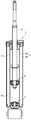
도 1은 일반적인 쇽 업소버를 도시한 도면이다.1 is a view showing a general shock absorber.
도 1에 도시된 바와 같이, 쇽 업소버(1)는 작동 유체가 충전된 실린더(2)와, 일단은 이 실린더(2) 내부에 위치하고 타단은 실린더(2) 외부로 연장되는 피스톤 로드(3)와, 피스톤 로드(3)의 일단에 장착되어 실린더(2) 내에서 왕복 운동하는 피스톤 밸브(4)를 포함한다.1, the shock absorber 1 includes a
이때, 실린더(2)는 내부관(2a)과 외부관(2b)으로 이루어질 수 있으며, 실린더(2)의 하단에는 피스톤 밸브(4)와 대향하도록 베이스 밸브(5)가 설치된다.At this time, the
한편, 실린더(2) 내부는 피스톤 밸브(4)에 의해 인장 챔버(C1)와 압축 챔버(C2)로 구획되는데, 피스톤 밸브(4)가 실린더(2) 내에서 상하 왕복 운동할 때, 피스톤 밸브(4)에 형성되어 있는 오리피스(미도시)를 통해 작동 유체가 인장 챔버(C1)로부터 압축 챔버(C2)로, 또는 압축 챔버(C2)로부터 인장 챔버(C1)로 유동하면서 감쇠력을 발생시키게 된다.On the other hand, the inside of the
그런데, 이와 같이 구성된 종래의 쇽 업소버(1)는, 차체에 연결된 피스톤 로드(3)의 직선 왕복 운동에 따라 발생되는 인장 챔버(C1)와 압축 챔버(C2)의 압력차를 이용하여 감쇠력을 발생시키도록 되어 있으므로, 피스톤 로드(3)의 이동 스트로크(stroke)가 크거나 저주파 충격 영역에서는 적절한 감쇠력이 발생하여 진동을 원활하게 흡수할 수 있지만, 피스톤 로드(3)의 이동 스트로크가 작거나 고주파 충격 영역에서는 문제가 있다.The conventional shock absorber 1 constructed as described above generates a damping force by using the pressure difference between the compression chamber C2 and the compression chamber C2 generated by the linear reciprocating motion of the
즉, 예를 들어 진폭이 작고 진동이 잦은 고주파 진동이나 충격이 가해지는 경우, 인장 챔버(C1)와 압축 챔버(C2)에서 발생되는 압력차가 작기 때문에, 피스톤 밸브(4)의 작동이 원활하지 못하여 적절한 감쇠력을 얻을 수 없고, 이에 따라 이러한 진동이 완전히 흡수되지 못하고 탑승자에게 전달되어 승차감을 저하시키게 된다.That is, for example, when a high-frequency vibration or shock with a small amplitude and frequent vibration is applied, the pressure difference generated between the tension chamber C1 and the compression chamber C2 is small, so that the operation of the piston valve 4 is not smooth A proper damping force can not be obtained, so that such vibration can not be completely absorbed and is transmitted to the occupant, thereby reducing the ride quality.
따라서, 충격의 입력 속도뿐만 아니라 주파수 차이에 따라 감쇠력을 조절할 필요가 있으며, 이를 위해 실린더를 상하 구획하는 메인 밸브유닛의 하부에 주파수 감응 밸브장치가 추가 장착된 쇽 업소버가 한국실용신안공개공보 제20-1995-0011204호(특허문헌 1) 등에서 공개된 바 있다.Therefore, it is necessary to adjust the damping force according to the frequency difference as well as the input speed of the shock. To this end, a shock absorber in which a frequency sensitive valve device is further provided below the main valve unit for vertically dividing the cylinder is disclosed in Korean Utility Model Laid- -1995-0011204 (Patent Document 1).
그런데, 주파수 감응 밸브장치가 장착된 종래의 쇽 업소버의 경우, 메인 밸브유닛 이외에, 속도 변화에 따라 추가되어 발생하는 압력을 제어하는 수단이 없고, 또한 순간적으로 큰 충격이 가해져 피스톤 로드의 이동 속도가 증가하는 고속 거동시에는, 감쇠력을 증가시켜 차체의 거동을 안정적으로 제어해야 할 필요가 있으나, 주파수 감응 밸브장치의 일측에 형성되는 바이패스 유로를 통해 유량이 빠져나감으로써 감쇠력이 손실되는 문제가 있다.However, in the case of a conventional shock absorber equipped with a frequency-responsive valve device, there is no means for controlling the pressure generated in addition to the main valve unit in addition to the speed change, and also a momentary great impact is applied, There is a problem in that the damping force is lost due to the escape of the flow rate through the bypass flow path formed at one side of the frequency response valve device .
예를 들어, 특허문헌 1에 개시된 쇽 업소버의 경우, 저주파 입력시 피스톤 밸브 뿐만 아니라, 로타리밸브의 오리피스를 통해서도 오일이 유동하게 되며, 따라서 고속 거동시 로타리밸브를 통한 감쇠력 손실이 발생하게 된다.
For example, in the case of the shock absorber disclosed in Patent Document 1, the oil flows not only through the orifice of the piston valve but also through the rotary valve at the time of low frequency input, so that the damping force loss through the rotary valve occurs at high speed.
본 발명은 상술한 바와 같은 문제를 해결하기 위해 안출된 것으로, 본 발명의 일실시예는, 압력에 따른 감쇠력 가변 효과와, 주파수 영역에 따른 감쇠력 가변 효과를 동시에 구현할 수 있는 쇽 업소버의 밸브 조립체와 관련된다.SUMMARY OF THE INVENTION It is an object of the present invention to provide a shock absorber valve assembly capable of simultaneously realizing a damping force variable effect according to a pressure and a variable damping force effect according to a frequency region, .
또한, 본 발명의 일실시예는, 압력 감응식 메인 밸브유닛 이외에 서브 밸브유닛을 구비함으로써, 속도 변화에 따라 추가 발생되는 압력을 제어할 수 있는 쇽 업소버의 밸브 조립체와 관련된다.In addition, an embodiment of the present invention relates to a valve assembly of a shock absorber that can control a pressure generated additionally in response to a speed change by providing a sub-valve unit in addition to the pressure-sensitive main valve unit.
또한, 본 발명의 일실시예는, 압력 감응식 메인 밸브유닛과 서브 밸브유닛, 및 주파수 감응식 밸브유닛을 함께 구비하되, 순간적으로 큰 충격이 가해지는 고속 거동시에는 주파수 감응식 밸브유닛으로부터 서브 밸브유닛으로 통하는 유로를 차단함으로써, 메인 밸브유닛 작동에 의해 감쇠력이 증대되는 쇽 업소버의 밸브 조립체와 관련된다.According to an embodiment of the present invention, a pressure-sensitive main valve unit, a sub-valve unit, and a frequency-sensitive valve unit are provided together, and at a high speed instantaneous large impact, And a damping force is increased by operation of the main valve unit by shutting off the flow path to the valve unit.
아울러, 본 발명의 일실시예는, 주파수 감응식 밸브에서의 스프링 마찰음을 방지할 수 있는 쇽 업소버의 밸브 조립체와 관련된다.
In addition, one embodiment of the present invention relates to a valve assembly of a shock absorber capable of preventing spring frictional noise in a frequency sensitive valve.
본 발명의 바람직한 일실시예에 의하면, 오리피스 홀이 형성된 피스톤 로드의 하단에 결합되고, 상기 오리피스 홀과 연통되도록 하단이 개방된 공간부가 내부에 형성되는 밸브 하우징; 상기 공간부를 상실과 하실로 구획하도록 설치되는 프리 피스톤과, 상기 프리 피스톤의 중앙에서 하향 연장 형성되는 하단 스토퍼를 포함하는 주파수감응 밸브유닛; 및 상기 공간부 하단에 결합되며, 압축 오리피스와 인장 오리피스가 관통 형성되는 서브 밸브유닛을 포함하며, 상기 프리 피스톤의 승강에 의해 상기 서브 밸브유닛의 작동이 제어되는 것을 특징으로 하며, 상기 서브 밸브유닛(400)은, 상기 공간부(210) 하단에 결합되는 밸브 본체(410)와, 상기 밸브 본체(410)의 상측에 구비되어 상기 압축 오리피스(412)를 개폐하는 석션밸브(420)를 포함하고, 상기 석션밸브(420)의 상측에 상기 석션밸브(420)를 상기 밸브 본체(410)의 상측으로 가압 지지하는 결합핀(450)이 결합되고, 상기 프리 피스톤(310) 하강시 상기 하단 스토퍼(330)가 상기 결합핀(450)의 상단에 지지되는 것을 특징으로 하는 쇽 업소버의 밸브 조립체가 제공된다.According to a preferred embodiment of the present invention, a valve housing is coupled to a lower end of a piston rod in which an orifice hole is formed, and a space portion having a lower end opened to communicate with the orifice hole is formed therein; A free piston installed to partition the space into a space and a space, and a lower stopper extending downward from a center of the free piston; And a sub valve unit coupled to a lower end of the space and having a compression orifice and a tension orifice formed therethrough, wherein operation of the sub valve unit is controlled by lifting and lowering the free piston, The
이때, 상기 프리 피스톤은, 상하 양측에 탄성부재의 일단이 각각 지지되는 지지부와, 상기 지지부의 둘레를 따라 하향 연장 형성되는 측벽을 포함한다.At this time, the free piston includes a support portion on which upper ends of the elastic members are respectively supported on upper and lower sides, and side walls extending downward along the periphery of the support portion.
또한, 상기 서브 밸브유닛은, 상기 측벽과 상기 석션밸브 사이에 측면유로가 형성된다.In the sub valve unit, a side flow path is formed between the side wall and the suction valve.
이때, 상기 하단 스토퍼의 탄성 변형시, 상기 측벽이 상기 석션밸브의 상측에 밀착 지지되어 상기 측면유로가 폐쇄된다.At this time, when the lower end stopper is elastically deformed, the side wall is tightly supported on the upper side of the suction valve to close the side flow path.
삭제delete
본 발명의 바람직한 일실시예에 따른 쇽 업소버의 밸브 조립체에 의하면, 압력 감응식 메인 밸브유닛과 서브 밸브유닛, 및 주파수 감응식 밸브유닛을 포함하므로, 압력에 따른 감쇠력 가변 효과와, 주파수 영역에 따른 감쇠력 가변 효과를 구현할 수 있다.The valve assembly of the shock absorber according to the preferred embodiment of the present invention includes the pressure-sensitive main valve unit, the sub-valve unit and the frequency-responsive valve unit, so that the variable damping force effect according to the pressure, A damping force variable effect can be realized.
또한, 속도 변화에 따라 추가 발생되는 압력을 서브 밸브유닛을 통해 제어할 수 있으므로, 승차감이 향상된다.Further, since the additional generated pressure can be controlled through the sub valve unit in accordance with the speed change, the ride comfort is improved.
또한, 순간적인 고속 거동시에는, 서브 밸브유닛으로 통하는 측면유로가 프리 피스톤에 의해 차단됨으로써, 메인 밸브유닛의 감쇠력이 증대되고, 차체가 안정적으로 거동할 수 있게 된다.Further, at the instantaneous high-speed jerk, the side flow path to the sub valve unit is blocked by the free piston, so that the damping force of the main valve unit is increased and the vehicle body can stably behave.
아울러, 원뿔대형 코일스프링의 적용에 의해, 주파수 감응식 밸브에서의 스프링 마찰음이 방지되므로, 감성 품질이 향상되는 효과가 있다.
In addition, by applying the cone-shaped coil spring, the spring friction sound of the frequency-responsive valve is prevented, thereby improving the sensibility of the sensation.
도 1은 일반적인 쇽 업소버의 단면도.
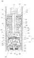
도 2는 본 발명의 일실시예에 따른 쇽 업소버의 밸브 조립체 초기 장착상태를 도시한 단면도.
도 3은 본 발명의 일실시예에 따른 서브 밸브유닛의 작동상태를 도시한 단면도.
도 4는 순간적으로 큰 충격이나 거동이 큰 진폭 입력시 측면유로가 폐쇄되어 서브 밸브유닛의 작동이 차단되는 상태를 도시한 단면도.1 is a sectional view of a general shock absorber;
FIG. 2 is a sectional view showing an initial mounting state of a valve assembly of a shock absorber according to an embodiment of the present invention; FIG.
3 is a cross-sectional view illustrating an operating state of a sub-valve unit according to an embodiment of the present invention.
4 is a cross-sectional view showing a state in which the side flow path is closed when the amplitude is large and the operation of the sub valve unit is shut off instantaneously with a large impact or behavior.
이하, 본 발명의 일실시예에 따른 쇽 업소버의 밸브 조립체에 대한 바람직한 실시예를 첨부된 도면을 참조하여 설명하기로 한다. 이 과정에서 도면에 도시된 선들의 두께나 구성요소의 크기 등은 설명의 명료성과 편의상 과장되게 도시되어 있을 수 있다.DETAILED DESCRIPTION OF THE PREFERRED EMBODIMENTS Hereinafter, preferred embodiments of a valve assembly of a shock absorber according to an embodiment of the present invention will be described with reference to the accompanying drawings. In this process, the thicknesses of the lines and the sizes of the components shown in the drawings may be exaggerated for clarity and convenience of explanation.
또한, 후술되는 용어들은 본 발명에서의 기능을 고려하여 정의된 용어들로서 이는 사용자, 운용자의 의도 또는 관례에 따라 달라질 수 있다. 그러므로, 이러한 용어들에 대한 정의는 본 명세서 전반에 걸친 내용을 토대로 하여 내려져야 할 것이다.In addition, the terms described below are defined in consideration of the functions of the present invention, which may vary depending on the intention or custom of the user, the operator. Therefore, definitions of these terms should be made based on the contents throughout this specification.
아울러, 아래의 실시예는 본 발명의 권리범위를 한정하는 것이 아니라 본 발명의 청구범위에 제시된 구성요소의 예시적인 사항에 불과하며, 본 발명의 명세서 전반에 걸친 기술사상에 포함되고 청구범위의 구성요소에서 균등물로서 치환 가능한 구성요소를 포함하는 실시예는 본 발명의 권리범위에 포함될 수 있다.
In addition, the following embodiments are not intended to limit the scope of the present invention, but merely as exemplifications of the constituent elements set forth in the claims of the present invention, and are included in technical ideas throughout the specification of the present invention, Embodiments that include components replaceable as equivalents in the elements may be included within the scope of the present invention.
실시예Example
도 2는 본 발명의 일실시예에 따른 쇽 업소버의 밸브 조립체 초기 장착상태를 도시한 단면도이고, 도 3은 본 발명의 일실시예에 따른 서브 밸브유닛의 작동상태를 도시한 단면도이며, 도 4는 순간적으로 큰 충격이나 거동이 큰 진폭 입력시 측면유로가 폐쇄되어 서브 밸브유닛의 작동이 차단되는 상태를 도시한 단면도이다.FIG. 2 is a sectional view showing an initial mounting state of a valve assembly of a shock absorber according to an embodiment of the present invention, FIG. 3 is a sectional view showing an operating state of a sub valve unit according to an embodiment of the present invention, Sectional view showing a state in which the side flow path is closed and the operation of the sub valve unit is shut off when a large amplitude or magnitude of an instantaneous large impact is inputted.
도 2에 도시된 바와 같이, 본 발명의 일실시예에 따른 쇽 업소버의 밸브 조립체(이하, '밸브 조립체')(100)는 피스톤 로드(11)의 하단에 결합되며, 주파수감응 밸브유닛(300)과 서브 밸브유닛(400)이 상하로 배치된다.2, a
더욱 상세하게는, 본 발명의 일실시예에 따른 밸브 조립체(100)는, 피스톤 로드(11)의 하단에 결합되는 밸브 하우징(200)과, 밸브 하우징(200) 내 공간부(210)에 설치되는 주파수감응 밸브유닛(300)과, 밸브 하우징(200)의 공간부(210) 하단에 결합되는 서브 밸브유닛(400)을 포함한다.The
이때, 메인 밸브유닛(500)은 밸브 조립체(100)의 상부에 위치하도록 피스톤 로드(11)의 외주면에 결합된다.At this time, the
여기서, 메인 밸브유닛(500)은 그 외주면이 실린더(13)의 내주면에 밀착되어 실린더(13) 내부를 인장 챔버(13a)와 압축 챔버(13b)로 상하 구획하는 밸브 몸체(510)와, 밸브 몸체(510)에 상하 방향으로 관통 형성되는 복수의 유로(521,522), 및 밸브 몸체(510)의 상측면과 하측면에 각각 구비되어 유로(521,522)를 개폐하는 리프 밸브(530)를 포함하여 이루어진다.The
이때, 유로(521,522)는 피스톤 로드(11)의 승강에 따른 인장 행정과 압축 행정시 개방 여부에 따라 인장 유로(522)와 압축 유로(521)로 구분될 수 있으며, 예를 들어 피스톤 로드(11)가 하강하는 압축 행정시 압축 챔버(13b)의 작동유체는 압축 유로(521)를 통해 인장 챔버(13a) 방향으로 상향 유동하게 된다.The
또한, 압축 유로(521)를 개폐하는 리프 밸브(530)의 상측과, 인장 유로(522)를 개폐하는 리프 밸브(530)의 하측에는 각각 리프 밸브(530)의 일측을 지지하는 한편, 유로 개방시 리프 밸브(530)의 휨 변형을 제한하도록 리테이너(541)와 함께 와셔(542)가 피스톤 로드(11)의 외주면에 결합된다.One side of the
피스톤 로드(11)는 오일 등 작동 유체가 충전된 실린더(13) 내에 축방향으로 설치되어 왕복 운동하며, 이때 실린더(13)는 하나의 단일관 형태로 이루어질 수도 있고 내부관과 외부관으로 구분되는 형태로 이루어지는 것도 가능하다.The
피스톤 로드(11)에는 밸브 하우징(200)의 공간부(210)와 연통하는 오리피스 홀(12)이 관통 형성된다. 이때, 오리피스 홀(12)의 일단은 피스톤 로드(11)의 외주면에 원주 방향을 따라 서로 이격하여 복수 개 형성될 수 있으며, 오리피스 홀(12)의 타단은 피스톤 로드(11)의 중심 축선을 따라 피스톤 로드(11)의 하단으로 연장된다.The
밸브 하우징(200) 내 공간부(210)에는 주파수감응 밸브유닛(300)이 설치된다. 여기서 주파수감응 밸브유닛(300)은 프리 피스톤(310)과, 프리 피스톤(310)의 상하 양측에 각각 개재되는 한 쌍의 탄성부재(320)를 포함하여 이루어질 수 있다.A frequency
이때, 프리 피스톤(310)은 상하 양측에 탄성부재(320)의 일단이 각각 지지되는 지지부(311)와, 지지부(311)의 둘레를 따라 하향 연장 형성되는 측벽(312)을 포함하여 이루어지며, 지지부(311)의 중앙에는 탄성 재질의 하단 스토퍼(330)가 하향 돌출 형성되어 프리 피스톤(310)의 하강 거리를 제한하게 된다.The
그리고, 지지부(311)의 둘레를 따라 탄성 재질의 상단 스토퍼(340)가 상향 돌출 형성되는데, 밸브 하우징(200)의 내주면 상측에는 프리 피스톤(310) 상승시 상단 스토퍼(340)가 걸리도록 걸림턱(220)이 형성되어 프리 피스톤(310)의 상승 거리를 제한하게 된다.An
한편, 프리 피스톤(310)은 인서트 사출에 의해 성형될 수 있는데, 예를 들어 금속 재질로서 하단이 개방된 원통 형태의 코어부재(313)를 준비하고, 그 외주면을 고무 또는 합성수지 등 탄성 재질의 표피층(314)이 감싸도록 일체 성형할 수 있다. 이때, 상단 스토퍼(340)와 하단 스토퍼(330)는 사출 성형되는 표피층(314)의 두께를 조절하여 형성한다.Meanwhile, the
아울러, 프리 피스톤(310)의 외주면이 밸브 하우징(200)의 공간부(210) 내주면에 밀착됨으로써 공간부(210)를 상하 구획하게 되는데, 이때 프리 피스톤(310)의 외주면에는 원주 방향으로 연장되는 복수의 실링돌기(315)가 돌출 형성되어 상하 공간부(210)를 실링할 수 있다.The
이하, 프리 피스톤(310)에 의해 구획된 상측 공간부(210)를 상실(211), 하측 공간부(210)를 하실(212)로 각각 지칭하기로 한다.Hereinafter, the
프리 피스톤(310)의 상하 양측에는 탄성부재(320)가 개재되며, 이에 따라 프리 피스톤(310)의 상하 이동시 탄성부재(320)는 신장 또는 압축되면서 프리 피스톤(310)에 탄성력을 제공하게 된다.The
이때, 탄성부재(320)는 코일스프링으로 이루어지는 것이 바람직하며, 특히 코일스프링의 형태는 원뿔대 형태인 것이 바람직한데, 이로써 코일스프링의 신장·압축시 코일스프링의 권선 간 충격 또는 마찰에 의한 소음 발생을 방지할 수 있다.In this case, it is preferable that the
주파수감응 밸브유닛(300)은, 차량 주행중 진폭이 낮은 고주파의 잔 충격을 흡수하는 역할을 한다. 즉, 공간부(210)로 유입되는 작동유체의 압력에 의해 프리 피스톤(310)이 승강하면서 탄성부재(320)에 의해 잔 충격이 흡수되는 것이며, 이때 프리 피스톤(310)의 승강 정도는 탄성부재(320)의 스프링 상수를 적절히 선택함으로써 결정할 수 있다.The frequency
한편, 저주파·고진폭의 충격이 전달되는 경우, 이를 효과적으로 감쇠하기 위해, 인장 행정시 프리 피스톤(310)에 의해 밸브 하우징(200) 공간부(210)의 상실(211)과 하실(212)이 연통되며, 상실(211)로부터 하실(212)로 유입된 작동유체가 공간부(210) 하단에 결합되는 서브 밸브유닛(400)을 통과하는 과정에서 추가 감쇠력이 발생하게 된다. 이때, 서브 밸브유닛(400)은 압입 또는 나사결합 등의 방식으로 밸브 하우징(200)에 결합될 수 있다.In order to effectively damp the low frequency and high amplitude shock, the
밸브 하우징(200)의 상실(211)로부터 하실(212)로 작동유체가 유입될 수 있도록 하기 위해, 공간부(210)의 내주면 일측에 아래쪽으로 갈수록 폭이 넓어지는 경사부(230)가 원주 방향을 따라 형성되고, 경사부(230)의 하단 내주면은 상단 내주면에 비해 폭이 넓은 확경부(240)를 형성한다.An
따라서, 저주파·고진폭의 충격이 발생하면, 오리피스 홀(12)을 통해 상실(211)로 유입되는 작동유체의 양이 급격히 증가하게 되며, 이렇게 유입되는 작동유체의 압력에 의해 도 3에 도시된 바와 같이 프리 피스톤(310)은 경사부(230)를 지나 확경부(240) 방향으로 하강하게 된다.Therefore, when an impact of a low frequency and a high amplitude is generated, the amount of the working fluid flowing into the
이때, 프리 피스톤(310)의 외주면과 공간부(210)의 내주면 사이에는 간극이 발생하게 되며, 이 간극으로 형성되는 유로를 통해 상실(211)의 작동유체가 하실(212)로 유입된다.At this time, a gap is formed between the outer circumferential surface of the
이처럼 하실(212)로 유입된 작동유체는 서브 밸브유닛(400)을 통과하는 과정에서 감쇠력을 발생시키는데, 이때 서브 밸브유닛(400)은 밸브 본체(410)와, 밸브 본체(410)에 상하 방향으로 관통 형성되는 인장 오리피스(411)와, 인장 오리피스(411)의 반경 방향 외측으로 형성되는 압축 오리피스(412)를 포함하여 구성된다.In this case, the
여기서, 밸브 본체(410)는 압입 또는 나사결합 등의 방식으로 밸브 하우징(200)의 공간부(210) 하단에 결합되는데, 밸브 본체(410)의 상측에는 압축 오리피스(412)를 개폐하는 단판의 석션밸브(420)가 구비되고, 밸브 본체(410)의 하측에는 인장 오리피스(411)를 개폐하는 다판 디스크(430)가 리테이너(441) 및 와셔(442)와 함께 구비된다. 이때, 석션밸브(420)와 다판 디스크(430) 및 리테이너(441)와 와셔(442)는 결합핀(450)에 의해 밸브 본체(410)에 고정된다.The
따라서, 저주파·고진폭의 충격 입력시, 프리 피스톤(310)을 밀고 하실(212)로 유입된 작동유체는 서브 밸브유닛(400)의 인장 오리피스(411)를 통해 다판 디스크(430)를 밀어내려 개방시키면서 압축 챔버(13b)로 유동하여 감쇠력을 발생시키게 되는 것이다.Accordingly, when a low-frequency / high-amplitude impact is input, the working fluid flowing into the
이때, 프리 피스톤(310)은 상실(211)로 유입되는 작동유체의 압력에 의해, 하단 스토퍼(330)가 결합핀(450)의 상단에 지지될 때까지 계속 하강하게 되며, 프리 피스톤(310)의 측벽(312) 하단과 석션밸브(420)의 상측면 사이에 형성되는 측면유로(460)를 통해 작동유체가 인장 오리피스(411)로 유동하게 된다.The
한편, 큰 충격이나 거동이 큰 진폭이 입력되면서 순간적으로 피스톤 로드(11)의 이동 속도가 증가하는 경우에는, 쇽 업소버의 감쇠력을 증대시켜 차체 거동을 제어할 필요가 있다.On the other hand, when the moving speed of the
이 경우, 본 발명의 일실시예에 의하면, 프리 피스톤(310)의 측벽(312)에 의해 측면유로(460, 도 3 참조)가 폐쇄되도록 함으로써, 서브 밸브유닛(400)을 통한 작동유체의 유동을 차단하고, 메인 밸브유닛(500)의 유로(521,522)를 통해서만 감쇠력이 발생되도록 한다.In this case, according to the embodiment of the present invention, the side flow path 460 (see FIG. 3) is closed by the
즉, 도 4에 도시된 바와 같이, 상실(211)로 유입되는 작동유체의 양이 증가하면서 작동유체의 압력에 의해 탄성 재질의 하단 스토퍼(330)가 밑으로 눌려서 변형되는 경우, 석션밸브(420)의 상부에 위치하고 있던 측벽(312)의 하단이 하강하여 석션밸브(420)의 상측에 밀착 지지됨으로써 측면유로(460, 도 3 참조)를 폐쇄하여, 서브 밸브유닛(400)을 통한 작동유체의 유동을 방지하게 된다.4, when the
이때, 작동유체는 메인 밸브유닛(500)의 유로(521,522)를 통과하면서 감쇠력을 발생시키게 되며, 서브 밸브유닛(400)의 오리피스(411,413)를 통한 작동유체의 유동이 차단됨으로써 쇽 업소버의 전체적인 감쇠력이 증대되는 것이다.At this time, the working fluid passes through the
100 : 밸브 조립체 200 : 밸브 하우징
300 : 주파수감응 밸브유닛 310 : 프리 피스톤
312 : 측벽 320 : 탄성부재
330 : 하단 스토퍼 400 : 서브 밸브유닛
410 : 밸브 본체 411 : 인장 오리피스
420 : 석션밸브 430 : 다판 디스크
450 : 핀부재 460 : 측면유로
500 : 메인 밸브유닛 510 : 밸브 몸체
521 : 압축 유로 522 : 인장 유로
530 : 리프 밸브100: valve assembly 200: valve housing
300: Frequency response valve unit 310: Free piston
312: side wall 320: elastic member
330: lower stopper 400: sub valve unit
410: valve body 411: tension orifice
420: Suction valve 430: Multi-plate disk
450: pin member 460: side channel
500: main valve unit 510: valve body
521: Compressed flow path 522: Tension flow path
530: Leaf valve
Claims (5)
Translated fromKorean상기 공간부를 상실과 하실로 구획하도록 설치되는 프리 피스톤과, 상기 프리 피스톤의 중앙에서 하향 연장 형성되는 하단 스토퍼를 포함하는 주파수감응 밸브유닛; 및
상기 공간부 하단에 결합되며, 압축 오리피스와 인장 오리피스가 관통 형성되는 서브 밸브유닛을 포함하며,
상기 프리 피스톤의 승강에 의해 상기 서브 밸브유닛의 작동이 제어되는 것을 특징으로 하며,
상기 서브 밸브유닛(400)은, 상기 공간부(210) 하단에 결합되는 밸브 본체(410)와, 상기 밸브 본체(410)의 상측에 구비되어 상기 압축 오리피스(412)를 개폐하는 석션밸브(420)를 포함하고, 상기 석션밸브(420)의 상측에 상기 석션밸브(420)를 상기 밸브 본체(410)의 상측으로 가압 지지하는 결합핀(450)이 결합되고, 상기 프리 피스톤(310) 하강시 상기 하단 스토퍼(330)가 상기 결합핀(450)의 상단에 지지되는 것을 특징으로 하는 쇽 업소버의 밸브 조립체.
A valve housing coupled to a lower end of a piston rod having an orifice hole formed therein and having a space portion opened at a lower end thereof to communicate with the orifice hole;
A free piston installed to partition the space into a space and a space, and a lower stopper extending downward from a center of the free piston; And
And a sub valve unit coupled to the lower end of the space and having a compression orifice and a tension orifice formed therethrough,
And the operation of the sub valve unit is controlled by lifting and lowering the free piston,
The sub valve unit 400 includes a valve body 410 coupled to the lower end of the space 210 and a suction valve 420 disposed on the valve body 410 to open and close the compression orifice 412. [ An engagement pin 450 for pressing the suction valve 420 to the upper side of the valve body 410 is coupled to an upper side of the suction valve 420, And the lower stopper (330) is supported on the upper end of the engagement pin (450).
상하 양측에 탄성부재(320)의 일단이 각각 지지되는 지지부(311)와, 상기 지지부(311)의 둘레를 따라 하향 연장 형성되는 측벽(312)을 포함하는 것을 특징으로 하는 쇽 업소버의 밸브 조립체.
[3] The apparatus according to claim 1, wherein the free piston (310)
And a side wall (312) extending downward along the periphery of the support portion (311). The valve assembly according to claim 1, wherein the elastic member (320)
상기 측벽(312)과 상기 석션밸브(420) 사이에 측면유로(460)가 형성되는 것을 특징으로 하는 쇽 업소버의 밸브 조립체.
The method of claim 2,
Wherein a side flow path (460) is formed between the side wall (312) and the suction valve (420).
상기 하단 스토퍼(330)의 탄성 변형시, 상기 측벽(312)이 상기 석션밸브(420)의 상측에 밀착 지지되어 상기 측면유로(460)가 폐쇄되는 것을 특징으로 하는 쇽 업소버의 밸브 조립체.
The method of claim 3,
When the lower end stopper (330) is elastically deformed, the side wall (312) is closely supported on the upper side of the suction valve (420) to close the side flow path (460).
Priority Applications (4)
| Application Number | Priority Date | Filing Date | Title |
|---|---|---|---|
| KR1020120088815AKR101594211B1 (en) | 2012-08-14 | 2012-08-14 | Valve assembly of shock absorber |
| CN201310349496.9ACN103591206B (en) | 2012-08-14 | 2013-08-12 | The valve assembly body of vibration damper |
| DE102013013683.0ADE102013013683B4 (en) | 2012-08-14 | 2013-08-13 | Valve arrangement of a vibration damper |
| US13/965,780US9086111B2 (en) | 2012-08-14 | 2013-08-13 | Valve assembly of shock absorber |
Applications Claiming Priority (1)
| Application Number | Priority Date | Filing Date | Title |
|---|---|---|---|
| KR1020120088815AKR101594211B1 (en) | 2012-08-14 | 2012-08-14 | Valve assembly of shock absorber |
Publications (2)
| Publication Number | Publication Date |
|---|---|
| KR20140022583A KR20140022583A (en) | 2014-02-25 |
| KR101594211B1true KR101594211B1 (en) | 2016-02-15 |
Family
ID=50029657
Family Applications (1)
| Application Number | Title | Priority Date | Filing Date |
|---|---|---|---|
| KR1020120088815AActiveKR101594211B1 (en) | 2012-08-14 | 2012-08-14 | Valve assembly of shock absorber |
Country Status (4)
| Country | Link |
|---|---|
| US (1) | US9086111B2 (en) |
| KR (1) | KR101594211B1 (en) |
| CN (1) | CN103591206B (en) |
| DE (1) | DE102013013683B4 (en) |
Cited By (1)
| Publication number | Priority date | Publication date | Assignee | Title |
|---|---|---|---|---|
| KR20220015569A (en) | 2020-07-31 | 2022-02-08 | 에스앤티모티브 주식회사 | Shock absorber with a frequency unit |
Families Citing this family (48)
| Publication number | Priority date | Publication date | Assignee | Title |
|---|---|---|---|---|
| US20100170760A1 (en) | 2009-01-07 | 2010-07-08 | John Marking | Remotely Operated Bypass for a Suspension Damper |
| US9452654B2 (en) | 2009-01-07 | 2016-09-27 | Fox Factory, Inc. | Method and apparatus for an adjustable damper |
| US9033122B2 (en) | 2009-01-07 | 2015-05-19 | Fox Factory, Inc. | Method and apparatus for an adjustable damper |
| US11306798B2 (en) | 2008-05-09 | 2022-04-19 | Fox Factory, Inc. | Position sensitive suspension damping with an active valve |
| US20120305350A1 (en) | 2011-05-31 | 2012-12-06 | Ericksen Everet O | Methods and apparatus for position sensitive suspension damping |
| US10047817B2 (en) | 2009-01-07 | 2018-08-14 | Fox Factory, Inc. | Method and apparatus for an adjustable damper |
| US8627932B2 (en) | 2009-01-07 | 2014-01-14 | Fox Factory, Inc. | Bypass for a suspension damper |
| US8857580B2 (en) | 2009-01-07 | 2014-10-14 | Fox Factory, Inc. | Remotely operated bypass for a suspension damper |
| US10060499B2 (en) | 2009-01-07 | 2018-08-28 | Fox Factory, Inc. | Method and apparatus for an adjustable damper |
| US8393446B2 (en) | 2008-08-25 | 2013-03-12 | David M Haugen | Methods and apparatus for suspension lock out and signal generation |
| US10036443B2 (en) | 2009-03-19 | 2018-07-31 | Fox Factory, Inc. | Methods and apparatus for suspension adjustment |
| US9422018B2 (en) | 2008-11-25 | 2016-08-23 | Fox Factory, Inc. | Seat post |
| US9140325B2 (en) | 2009-03-19 | 2015-09-22 | Fox Factory, Inc. | Methods and apparatus for selective spring pre-load adjustment |
| US10821795B2 (en) | 2009-01-07 | 2020-11-03 | Fox Factory, Inc. | Method and apparatus for an adjustable damper |
| US11299233B2 (en) | 2009-01-07 | 2022-04-12 | Fox Factory, Inc. | Method and apparatus for an adjustable damper |
| US12122205B2 (en) | 2009-01-07 | 2024-10-22 | Fox Factory, Inc. | Active valve for an internal bypass |
| US9038791B2 (en) | 2009-01-07 | 2015-05-26 | Fox Factory, Inc. | Compression isolator for a suspension damper |
| US8936139B2 (en) | 2009-03-19 | 2015-01-20 | Fox Factory, Inc. | Methods and apparatus for suspension adjustment |
| EP2312180B1 (en) | 2009-10-13 | 2019-09-18 | Fox Factory, Inc. | Apparatus for controlling a fluid damper |
| US8672106B2 (en) | 2009-10-13 | 2014-03-18 | Fox Factory, Inc. | Self-regulating suspension |
| US10697514B2 (en) | 2010-01-20 | 2020-06-30 | Fox Factory, Inc. | Remotely operated bypass for a suspension damper |
| EP2402239B1 (en) | 2010-07-02 | 2020-09-02 | Fox Factory, Inc. | Adjustable seat post |
| EP3929459A1 (en) | 2011-09-12 | 2021-12-29 | Fox Factory, Inc. | Methods and apparatus for suspension set up |
| US11279199B2 (en) | 2012-01-25 | 2022-03-22 | Fox Factory, Inc. | Suspension damper with by-pass valves |
| US10330171B2 (en) | 2012-05-10 | 2019-06-25 | Fox Factory, Inc. | Method and apparatus for an adjustable damper |
| US9638280B2 (en) | 2013-08-26 | 2017-05-02 | Tenneco Automotive Operating Company Inc. | Shock absorber with frequency dependent passive valve |
| JP6108550B2 (en)* | 2013-09-19 | 2017-04-05 | Kyb株式会社 | Shock absorber |
| US9500255B2 (en)* | 2014-02-28 | 2016-11-22 | Tenneco Automotive Operating Company Inc. | Shock absorber with frequency dependent passive valve |
| KR102161566B1 (en)* | 2014-03-28 | 2020-10-05 | 주식회사 만도 | Shock absorber |
| DE102014210705A1 (en)* | 2014-06-05 | 2015-12-17 | Zf Friedrichshafen Ag | Frequency-dependent damping valve arrangement |
| DE102014210704B4 (en)* | 2014-06-05 | 2016-11-24 | Zf Friedrichshafen Ag | Frequency-dependent damping valve arrangement |
| US9441700B2 (en)* | 2014-08-14 | 2016-09-13 | Tenneco Automotive Operating Company Inc. | Shock absorber with frequency dependent passive valve |
| JP6359761B2 (en)* | 2014-10-01 | 2018-07-18 | ベイジンウェスト・インダストリーズ・カンパニー・リミテッドBeijingwest Industries Co., Ltd. | Damper assembly |
| JP6395598B2 (en)* | 2014-12-26 | 2018-09-26 | 株式会社ショーワ | Pressure shock absorber |
| ITUB20151830A1 (en)* | 2015-07-02 | 2017-01-02 | Sistemi Sospensioni Spa | Hydraulic compression pad for hydraulic shock absorber for vehicle suspension, with pressure limiting device. |
| US10737546B2 (en) | 2016-04-08 | 2020-08-11 | Fox Factory, Inc. | Electronic compression and rebound control |
| DE102016208845A1 (en)* | 2016-05-23 | 2017-11-23 | Thyssenkrupp Ag | Frequency-selective vibration damper for motor vehicles with a bypass control valve |
| CN106523576B (en)* | 2016-11-29 | 2018-09-07 | 广东机电职业技术学院 | Rate-sensitive type damper |
| US10563721B2 (en)* | 2017-04-24 | 2020-02-18 | Beijingwest Industries Co., Ltd | Hydraulic damper having a high frequency valve assembly |
| WO2019021797A1 (en) | 2017-07-26 | 2019-01-31 | 日立オートモティブシステムズ株式会社 | Damper and method for manufacturing same |
| KR102546371B1 (en)* | 2019-01-02 | 2023-06-22 | 현대모비스 주식회사 | Suspension for vehicle |
| WO2020157794A1 (en)* | 2019-01-28 | 2020-08-06 | 三和パッキング工業株式会社 | Shock-absorbing device and metal cover |
| US12031606B2 (en) | 2019-06-26 | 2024-07-09 | Hitachi Astemo, Ltd. | Shock absorber |
| CN112360912B (en)* | 2019-11-27 | 2022-09-16 | 浙江万向马瑞利减震器有限公司 | Shock absorber with FRD valve |
| CN111043221B (en)* | 2020-01-06 | 2021-06-15 | 北京京西重工有限公司 | Damper assembly |
| KR102804966B1 (en)* | 2020-03-04 | 2025-05-16 | 멀티매틱 인코퍼레이티드 | Improved hydraulic damper spool valve |
| CN111288109B (en)* | 2020-03-25 | 2021-11-09 | 东风小康汽车有限公司重庆分公司 | Damping piston assembly |
| JP7492390B2 (en)* | 2020-07-06 | 2024-05-29 | カヤバ株式会社 | Shock absorber |
Citations (2)
| Publication number | Priority date | Publication date | Assignee | Title |
|---|---|---|---|---|
| US5129488A (en) | 1989-11-16 | 1992-07-14 | Atsugi Unisia Corporation | Vibration mode responsive variable damping force shock absorber with feature of automatic selection of damping mode depending upon vibration mode of vehicular body |
| JP2011007213A (en)* | 2009-06-23 | 2011-01-13 | Kyb Co Ltd | Buffer |
Family Cites Families (11)
| Publication number | Priority date | Publication date | Assignee | Title |
|---|---|---|---|---|
| CA2042133C (en) | 1990-07-10 | 1997-09-09 | Hiroaki Kita | Equipment for transporting a load |
| JPH06147252A (en)* | 1992-09-18 | 1994-05-27 | Tokico Ltd | Hydraulic buffer |
| KR960000776Y1 (en) | 1993-10-12 | 1996-01-27 | 만도기계 주식회사 | Damping force variable hydraulic shock absorber with frequency sensitive valve device |
| JP3678830B2 (en)* | 1996-01-22 | 2005-08-03 | カヤバ工業株式会社 | Hydraulic shock absorber |
| KR101288609B1 (en)* | 2008-07-03 | 2013-07-22 | 주식회사 만도 | Damping force controlling valve |
| KR101383380B1 (en)* | 2009-12-11 | 2014-04-17 | 카야바 고교 가부시기가이샤 | Shock-absorbing device |
| JP5758119B2 (en)* | 2010-03-03 | 2015-08-05 | 日立オートモティブシステムズ株式会社 | Shock absorber |
| KR101254233B1 (en) | 2011-05-31 | 2013-04-18 | 주식회사 만도 | Valve structure of a shock absorber |
| KR101254287B1 (en)* | 2011-06-09 | 2013-04-12 | 주식회사 만도 | Valve structure having variable flow valve of a shock absorber |
| KR101288612B1 (en)* | 2011-07-21 | 2013-07-22 | 주식회사 만도 | Valve structure of a shock absorber |
| JP5758235B2 (en)* | 2011-08-31 | 2015-08-05 | 日立オートモティブシステムズ株式会社 | Shock absorber |
- 2012
- 2012-08-14KRKR1020120088815Apatent/KR101594211B1/enactiveActive
- 2013
- 2013-08-12CNCN201310349496.9Apatent/CN103591206B/enactiveActive
- 2013-08-13USUS13/965,780patent/US9086111B2/enactiveActive
- 2013-08-13DEDE102013013683.0Apatent/DE102013013683B4/enactiveActive
Patent Citations (2)
| Publication number | Priority date | Publication date | Assignee | Title |
|---|---|---|---|---|
| US5129488A (en) | 1989-11-16 | 1992-07-14 | Atsugi Unisia Corporation | Vibration mode responsive variable damping force shock absorber with feature of automatic selection of damping mode depending upon vibration mode of vehicular body |
| JP2011007213A (en)* | 2009-06-23 | 2011-01-13 | Kyb Co Ltd | Buffer |
Cited By (1)
| Publication number | Priority date | Publication date | Assignee | Title |
|---|---|---|---|---|
| KR20220015569A (en) | 2020-07-31 | 2022-02-08 | 에스앤티모티브 주식회사 | Shock absorber with a frequency unit |
Also Published As
| Publication number | Publication date |
|---|---|
| CN103591206B (en) | 2016-04-06 |
| US9086111B2 (en) | 2015-07-21 |
| DE102013013683A1 (en) | 2014-02-20 |
| US20140048365A1 (en) | 2014-02-20 |
| DE102013013683B4 (en) | 2019-03-07 |
| CN103591206A (en) | 2014-02-19 |
| KR20140022583A (en) | 2014-02-25 |
Similar Documents
| Publication | Publication Date | Title |
|---|---|---|
| KR101594211B1 (en) | Valve assembly of shock absorber | |
| KR101254287B1 (en) | Valve structure having variable flow valve of a shock absorber | |
| KR101350078B1 (en) | Piston valve of shock absorber | |
| KR101254233B1 (en) | Valve structure of a shock absorber | |
| KR101375804B1 (en) | Shock absorber with a frequency and pressure unit | |
| KR101876915B1 (en) | Piston valve assembly of shock absorber | |
| KR20110002667A (en) | Shock Absorber Hydraulic Stopper | |
| KR20180083725A (en) | Shock absorber | |
| KR101539490B1 (en) | Valve assembly of dual frequency sensitive type | |
| CN107345549A (en) | Suspension system and its damper | |
| KR101325743B1 (en) | Valve structure of a shock absorber | |
| KR101218838B1 (en) | Valve structure of a shock absorber | |
| KR20120030747A (en) | Piston valve assembly for shock absorber | |
| KR101756421B1 (en) | Shock absorber with a frequency unit | |
| KR101337582B1 (en) | Shock absorber with a frequency unit | |
| KR101662223B1 (en) | Shock absorber with a frequency unit | |
| KR101229443B1 (en) | Damping force variable valve of a shock absorber | |
| KR20090036211A (en) | Shock absorber | |
| KR960004424Y1 (en) | Damping valve of shock absorber for a vehicle | |
| KR101337856B1 (en) | Damping force variable shock absorber | |
| KR101254283B1 (en) | Valve structure of a shock absorber | |
| KR101426794B1 (en) | Base valve assembly of frequency sensitive type | |
| KR20110085202A (en) | Shock absorber valve structure | |
| KR20120030278A (en) | Piston valve assembly for shock absorber | |
| KR20040088678A (en) | shock absorber |
Legal Events
| Date | Code | Title | Description |
|---|---|---|---|
| PA0109 | Patent application | St.27 status event code:A-0-1-A10-A12-nap-PA0109 | |
| P11-X000 | Amendment of application requested | St.27 status event code:A-2-2-P10-P11-nap-X000 | |
| P13-X000 | Application amended | St.27 status event code:A-2-2-P10-P13-nap-X000 | |
| PG1501 | Laying open of application | St.27 status event code:A-1-1-Q10-Q12-nap-PG1501 | |
| A201 | Request for examination | ||
| PA0201 | Request for examination | St.27 status event code:A-1-2-D10-D11-exm-PA0201 | |
| R18-X000 | Changes to party contact information recorded | St.27 status event code:A-3-3-R10-R18-oth-X000 | |
| PN2301 | Change of applicant | St.27 status event code:A-3-3-R10-R11-asn-PN2301 | |
| R19-X000 | Request for party data change rejected | St.27 status event code:A-3-3-R10-R19-oth-X000 | |
| N231 | Notification of change of applicant | ||
| PN2301 | Change of applicant | St.27 status event code:A-3-3-R10-R13-asn-PN2301 St.27 status event code:A-3-3-R10-R11-asn-PN2301 | |
| E902 | Notification of reason for refusal | ||
| PE0902 | Notice of grounds for rejection | St.27 status event code:A-1-2-D10-D21-exm-PE0902 | |
| T11-X000 | Administrative time limit extension requested | St.27 status event code:U-3-3-T10-T11-oth-X000 | |
| E13-X000 | Pre-grant limitation requested | St.27 status event code:A-2-3-E10-E13-lim-X000 | |
| P11-X000 | Amendment of application requested | St.27 status event code:A-2-2-P10-P11-nap-X000 | |
| P13-X000 | Application amended | St.27 status event code:A-2-2-P10-P13-nap-X000 | |
| PE0801 | Dismissal of amendment | St.27 status event code:A-2-2-P10-P12-nap-PE0801 | |
| E701 | Decision to grant or registration of patent right | ||
| PE0701 | Decision of registration | St.27 status event code:A-1-2-D10-D22-exm-PE0701 | |
| GRNT | Written decision to grant | ||
| PR0701 | Registration of establishment | St.27 status event code:A-2-4-F10-F11-exm-PR0701 | |
| PR1002 | Payment of registration fee | St.27 status event code:A-2-2-U10-U11-oth-PR1002 Fee payment year number:1 | |
| PG1601 | Publication of registration | St.27 status event code:A-4-4-Q10-Q13-nap-PG1601 | |
| FPAY | Annual fee payment | Payment date:20181226 Year of fee payment:4 | |
| PR1001 | Payment of annual fee | St.27 status event code:A-4-4-U10-U11-oth-PR1001 Fee payment year number:4 | |
| FPAY | Annual fee payment | Payment date:20191219 Year of fee payment:5 | |
| PR1001 | Payment of annual fee | St.27 status event code:A-4-4-U10-U11-oth-PR1001 Fee payment year number:5 | |
| PN2301 | Change of applicant | St.27 status event code:A-5-5-R10-R13-asn-PN2301 St.27 status event code:A-5-5-R10-R11-asn-PN2301 | |
| PR1001 | Payment of annual fee | St.27 status event code:A-4-4-U10-U11-oth-PR1001 Fee payment year number:6 | |
| PN2301 | Change of applicant | St.27 status event code:A-5-5-R10-R13-asn-PN2301 St.27 status event code:A-5-5-R10-R11-asn-PN2301 | |
| PR1001 | Payment of annual fee | St.27 status event code:A-4-4-U10-U11-oth-PR1001 Fee payment year number:7 | |
| PN2301 | Change of applicant | St.27 status event code:A-5-5-R10-R13-asn-PN2301 St.27 status event code:A-5-5-R10-R11-asn-PN2301 | |
| PR1001 | Payment of annual fee | St.27 status event code:A-4-4-U10-U11-oth-PR1001 Fee payment year number:8 | |
| PR1001 | Payment of annual fee | St.27 status event code:A-4-4-U10-U11-oth-PR1001 Fee payment year number:9 | |
| PR1001 | Payment of annual fee | St.27 status event code:A-4-4-U10-U11-oth-PR1001 Fee payment year number:10 | |
| R18-X000 | Changes to party contact information recorded | St.27 status event code:A-5-5-R10-R18-oth-X000 |