KR101592583B1 - Film forming apparatus, method of cleaning film forming apparatus, and computer readable storage medium - Google Patents
Film forming apparatus, method of cleaning film forming apparatus, and computer readable storage mediumDownload PDFInfo
- Publication number
- KR101592583B1 KR101592583B1KR1020090111181AKR20090111181AKR101592583B1KR 101592583 B1KR101592583 B1KR 101592583B1KR 1020090111181 AKR1020090111181 AKR 1020090111181AKR 20090111181 AKR20090111181 AKR 20090111181AKR 101592583 B1KR101592583 B1KR 101592583B1
- Authority
- KR
- South Korea
- Prior art keywords
- gas
- susceptor
- cleaning
- film forming
- forming apparatus
- Prior art date
- Legal status (The legal status is an assumption and is not a legal conclusion. Google has not performed a legal analysis and makes no representation as to the accuracy of the status listed.)
- Expired - Fee Related
Links
Images


Classifications
- B—PERFORMING OPERATIONS; TRANSPORTING
- B08—CLEANING
- B08B—CLEANING IN GENERAL; PREVENTION OF FOULING IN GENERAL
- B08B7/00—Cleaning by methods not provided for in a single other subclass or a single group in this subclass
- B08B7/0035—Cleaning by methods not provided for in a single other subclass or a single group in this subclass by radiant energy, e.g. UV, laser, light beam or the like
- C—CHEMISTRY; METALLURGY
- C23—COATING METALLIC MATERIAL; COATING MATERIAL WITH METALLIC MATERIAL; CHEMICAL SURFACE TREATMENT; DIFFUSION TREATMENT OF METALLIC MATERIAL; COATING BY VACUUM EVAPORATION, BY SPUTTERING, BY ION IMPLANTATION OR BY CHEMICAL VAPOUR DEPOSITION, IN GENERAL; INHIBITING CORROSION OF METALLIC MATERIAL OR INCRUSTATION IN GENERAL
- C23C—COATING METALLIC MATERIAL; COATING MATERIAL WITH METALLIC MATERIAL; SURFACE TREATMENT OF METALLIC MATERIAL BY DIFFUSION INTO THE SURFACE, BY CHEMICAL CONVERSION OR SUBSTITUTION; COATING BY VACUUM EVAPORATION, BY SPUTTERING, BY ION IMPLANTATION OR BY CHEMICAL VAPOUR DEPOSITION, IN GENERAL
- C23C16/00—Chemical coating by decomposition of gaseous compounds, without leaving reaction products of surface material in the coating, i.e. chemical vapour deposition [CVD] processes
- C23C16/44—Chemical coating by decomposition of gaseous compounds, without leaving reaction products of surface material in the coating, i.e. chemical vapour deposition [CVD] processes characterised by the method of coating
- C23C16/4401—Means for minimising impurities, e.g. dust, moisture or residual gas, in the reaction chamber
- C23C16/4405—Cleaning of reactor or parts inside the reactor by using reactive gases
- H—ELECTRICITY
- H01—ELECTRIC ELEMENTS
- H01L—SEMICONDUCTOR DEVICES NOT COVERED BY CLASS H10
- H01L21/00—Processes or apparatus adapted for the manufacture or treatment of semiconductor or solid state devices or of parts thereof
- H01L21/67—Apparatus specially adapted for handling semiconductor or electric solid state devices during manufacture or treatment thereof; Apparatus specially adapted for handling wafers during manufacture or treatment of semiconductor or electric solid state devices or components ; Apparatus not specifically provided for elsewhere
- H01L21/67005—Apparatus not specifically provided for elsewhere
- H01L21/67011—Apparatus for manufacture or treatment
- H01L21/67017—Apparatus for fluid treatment
- H01L21/67028—Apparatus for fluid treatment for cleaning followed by drying, rinsing, stripping, blasting or the like
- H—ELECTRICITY
- H01—ELECTRIC ELEMENTS
- H01L—SEMICONDUCTOR DEVICES NOT COVERED BY CLASS H10
- H01L21/00—Processes or apparatus adapted for the manufacture or treatment of semiconductor or solid state devices or of parts thereof
- H01L21/67—Apparatus specially adapted for handling semiconductor or electric solid state devices during manufacture or treatment thereof; Apparatus specially adapted for handling wafers during manufacture or treatment of semiconductor or electric solid state devices or components ; Apparatus not specifically provided for elsewhere
- H01L21/683—Apparatus specially adapted for handling semiconductor or electric solid state devices during manufacture or treatment thereof; Apparatus specially adapted for handling wafers during manufacture or treatment of semiconductor or electric solid state devices or components ; Apparatus not specifically provided for elsewhere for supporting or gripping
- H01L21/687—Apparatus specially adapted for handling semiconductor or electric solid state devices during manufacture or treatment thereof; Apparatus specially adapted for handling wafers during manufacture or treatment of semiconductor or electric solid state devices or components ; Apparatus not specifically provided for elsewhere for supporting or gripping using mechanical means, e.g. chucks, clamps or pinches
- H01L21/68714—Apparatus specially adapted for handling semiconductor or electric solid state devices during manufacture or treatment thereof; Apparatus specially adapted for handling wafers during manufacture or treatment of semiconductor or electric solid state devices or components ; Apparatus not specifically provided for elsewhere for supporting or gripping using mechanical means, e.g. chucks, clamps or pinches the wafers being placed on a susceptor, stage or support
- H01L21/68764—Apparatus specially adapted for handling semiconductor or electric solid state devices during manufacture or treatment thereof; Apparatus specially adapted for handling wafers during manufacture or treatment of semiconductor or electric solid state devices or components ; Apparatus not specifically provided for elsewhere for supporting or gripping using mechanical means, e.g. chucks, clamps or pinches the wafers being placed on a susceptor, stage or support characterised by a movable susceptor, stage or support, others than those only rotating on their own vertical axis, e.g. susceptors on a rotating caroussel
- H—ELECTRICITY
- H01—ELECTRIC ELEMENTS
- H01L—SEMICONDUCTOR DEVICES NOT COVERED BY CLASS H10
- H01L21/00—Processes or apparatus adapted for the manufacture or treatment of semiconductor or solid state devices or of parts thereof
- H01L21/67—Apparatus specially adapted for handling semiconductor or electric solid state devices during manufacture or treatment thereof; Apparatus specially adapted for handling wafers during manufacture or treatment of semiconductor or electric solid state devices or components ; Apparatus not specifically provided for elsewhere
- H01L21/683—Apparatus specially adapted for handling semiconductor or electric solid state devices during manufacture or treatment thereof; Apparatus specially adapted for handling wafers during manufacture or treatment of semiconductor or electric solid state devices or components ; Apparatus not specifically provided for elsewhere for supporting or gripping
- H01L21/687—Apparatus specially adapted for handling semiconductor or electric solid state devices during manufacture or treatment thereof; Apparatus specially adapted for handling wafers during manufacture or treatment of semiconductor or electric solid state devices or components ; Apparatus not specifically provided for elsewhere for supporting or gripping using mechanical means, e.g. chucks, clamps or pinches
- H01L21/68714—Apparatus specially adapted for handling semiconductor or electric solid state devices during manufacture or treatment thereof; Apparatus specially adapted for handling wafers during manufacture or treatment of semiconductor or electric solid state devices or components ; Apparatus not specifically provided for elsewhere for supporting or gripping using mechanical means, e.g. chucks, clamps or pinches the wafers being placed on a susceptor, stage or support
- H01L21/68771—Apparatus specially adapted for handling semiconductor or electric solid state devices during manufacture or treatment thereof; Apparatus specially adapted for handling wafers during manufacture or treatment of semiconductor or electric solid state devices or components ; Apparatus not specifically provided for elsewhere for supporting or gripping using mechanical means, e.g. chucks, clamps or pinches the wafers being placed on a susceptor, stage or support characterised by supporting more than one semiconductor substrate
Landscapes
- Engineering & Computer Science (AREA)
- Physics & Mathematics (AREA)
- Chemical & Material Sciences (AREA)
- Condensed Matter Physics & Semiconductors (AREA)
- General Physics & Mathematics (AREA)
- Manufacturing & Machinery (AREA)
- Computer Hardware Design (AREA)
- Microelectronics & Electronic Packaging (AREA)
- Power Engineering (AREA)
- Optics & Photonics (AREA)
- General Chemical & Material Sciences (AREA)
- Chemical Kinetics & Catalysis (AREA)
- Materials Engineering (AREA)
- Mechanical Engineering (AREA)
- Metallurgy (AREA)
- Organic Chemistry (AREA)
- Chemical Vapour Deposition (AREA)
- Plasma & Fusion (AREA)
Abstract
Translated fromKorean
Description
Translated fromKorean본 출원은 2008년 11월 19일 및 2009년 11월 5일에 일본 특허청에 각각 출원된 일본 특허 출원 제2008-295640호 및 일본 특허 출원 제2009-253593호에 기초하는 우선권을 주장하는 것으로, 그 출원의 모든 내용을 참조함으로써 포함하는 것이다.The present application claims priority based on Japanese Patent Application No. 2008-295640 and Japanese Patent Application No. 2009-253593, both filed with the Japanese Patent Office on November 19, 2008 and November 5, 2009, By reference to the entire contents of the application.
본 발명은 반도체 장치 등의 제조에 사용되는 성막 장치, 성막 장치의 클리닝 방법 및 이 클리닝 방법을 성막 장치에 실시시키는 프로그램을 기억하는 컴퓨터 판독 가능 기억 매체에 관한 것이다.The present invention relates to a film forming apparatus used for manufacturing semiconductor devices and the like, a method for cleaning a film forming apparatus, and a computer readable storage medium storing a program for causing the film forming apparatus to perform the cleaning method.
반도체 장치 등의 제조에 사용되는 성막 장치에 있어서는, 기판에 뿐만 아니라, 기판이 적재되는 서셉터의 상면에도 막이 퇴적된다. 퇴적 프로세스가 반복되어, 서셉터에 퇴적된 막의 두께가 일정 정도가 되면, 박리되어 파티클을 발생한다. 그로 인해, 소정의 클리닝 가스를 공급함으로써 서셉터에 퇴적된 막을 제거하는 클리닝이 행해진다(예를 들어, 일본 특허 출원 공개 제2000-167383호 공보 및 일본 특허 출원 공개 제2002-313727호 공보).In a film forming apparatus used for manufacturing a semiconductor device or the like, a film is deposited not only on the substrate but also on the upper surface of the susceptor on which the substrate is placed. When the deposition process is repeated and the thickness of the film deposited on the susceptor reaches a certain level, it is peeled off and particles are generated. As a result, cleaning is performed to remove the film deposited on the susceptor by supplying a predetermined cleaning gas (for example, Japanese Unexamined Patent Application Publication No. 2000-167383 and Japanese Unexamined Patent Application Publication No. 2002-313727).
서셉터의 클리닝에 사용하는 클리닝 가스는, 예를 들어 산화 실리콘막이나 질화 실리콘막의 에칭에도 사용할 수 있는 가스로, 예를 들어 스테인리스강이나 알루미늄으로 제작되는 챔버 내면에 대해서도 부식성을 갖고 있다. 이로 인해, 내부식성이 높은 재료로 챔버를 제작하거나, 내면을 코팅할 필요가 생겨, 챔버의 제조 비용이 상승해 버린다고 하는 문제가 있다.The cleaning gas used for cleaning the susceptor is a gas which can also be used for etching, for example, a silicon oxide film or a silicon nitride film, and is also corrosive to the inner surface of a chamber made of, for example, stainless steel or aluminum. As a result, there is a problem that the chamber needs to be made of a material having high corrosion resistance or to coat the inner surface, resulting in an increase in the manufacturing cost of the chamber.
본 발명은 상기한 사정을 감안하여, 챔버의 내면이 클리닝 가스에 과잉으로 노출되지 않고, 서셉터 상의 퇴적물을 제거하는 것이 가능한 성막 장치, 성막 장치의 클리닝 방법 및 이 클리닝 방법을 성막 장치에 실시시키는 프로그램 및 이것을 기억하는 컴퓨터 판독 가능 기억 매체를 제공한다.SUMMARY OF THE INVENTION In view of the above circumstances, it is an object of the present invention to provide a film forming apparatus capable of removing deposits on a susceptor without excessively exposing the inner surface of the chamber to cleaning gas, a cleaning method of a film forming apparatus, And a computer-readable storage medium storing the program.
본 발명의 제1 형태는, 용기 내에 회전 가능하게 설치되는 서셉터와, 상기 서셉터의 하나의 면에 설치되어, 기판이 적재되는 기판 적재 영역과, 상기 서셉터의 상기 하나의 면에 대해, 원료 가스를 공급하는 원료 가스 공급계와, 상기 서셉터의 상방에 있어서 상기 하나의 면을 향해 개방되어 역오목 형상의 공간을 구획하는 제1 오목 형상 부재와, 상기 제1 오목 형상 부재와의 사이에 가스 유로를 구획하도록 상기 제1 오목 형상 부재를 덮는 제2 오목 형상 부재와, 상기 역오목 형상의 공간에 클리닝 가스를 공급하는 클리닝 가스 공급부와, 상기 가스 유로에 연통하여, 상기 용기의 외부로 연장되는 배기관을 포함하는 클리닝용 구조체 및 상기 원료 가스를 배기하기 위해 상기 용기에 형성되는 배기구를 구비하는 성막 장치를 제공한다.A first aspect of the present invention is a substrate processing apparatus comprising: a susceptor rotatably installed in a container; a substrate mounting region provided on one surface of the susceptor and on which a substrate is mounted; A first concave member that opens toward the one surface and separates a space of an inverted concave shape above the susceptor; and a second concave member that opens toward the one surface and forms a space between the first concave member and the first concave member, A second concave member that covers the first concave member so as to partition the gas flow path in the gas inlet, a cleaning gas supply unit that supplies cleaning gas to the reverse concave space, A cleaning structure including an exhaust pipe extending therefrom, and an exhaust port formed in the container for exhausting the source gas.
본 발명의 제2 형태는, 성막 장치의 용기 내에 회전 가능하게 설치되어, 기판이 적재되는 기판 적재 영역을 하나의 면에 포함하는 서셉터를 회전하는 스텝과, 상기 서셉터의 상방에 배치되어, 상기 서셉터의 상기 하나의 면을 향해 개방되는 제1 오목 형상 부재에 의해 구획되는 역오목 형상의 공간에 클리닝 가스를 공급하는 스텝과, 상기 제1 오목 형상 부재와, 상기 제1 오목 형상 부재를 덮는 제2 오목형상 부재 사이에 구획 형성되는 가스 유로를 통해 상기 클리닝 가스를 배기하는 스텝을 구비하는, 성막 장치의 클리닝 방법을 제공한다.A second aspect of the present invention is a method for manufacturing a semiconductor device, comprising: a step of rotating a susceptor rotatably installed in a container of a film forming apparatus, the susceptor including a substrate mounting region on which a substrate is mounted, Supplying a cleaning gas to a reverse concave space defined by a first concave member opened toward the one surface of the susceptor; and a step of supplying cleaning gas to the first concave member and the first concave member And a step of discharging the cleaning gas through a gas flow passage defined between the second concave members which cover the first concave members.
본 발명의 제3 형태는, 성막 장치의 용기 내에 회전 가능하게 설치되어, 기판이 적재되는 기판 적재 영역을 하나의 면에 포함하는 서셉터를 회전하는 스텝과, 상기 서셉터의 상방에 배치되어, 상기 서셉터의 상기 하나의 면을 향해 개방되는 제1 오목 형상 부재에 의해 구획되는 역오목 형상의 공간에 클리닝 가스를 공급하는 스텝과, 상기 제1 오목 형상 부재와, 상기 제1 오목 형상 부재를 덮는 제2 오목형상 부재 사이에 구획 형성되는 가스 유로를 통해 상기 클리닝 가스를 배기하는 스텝을 구비하는, 성막 장치의 클리닝 방법을 제1 형태의 성막 장치에 실시시키는 프로그램을 기억하는 컴퓨터 판독 가능 기억 매체를 제공한다.A third aspect of the present invention is a manufacturing method of a film forming apparatus, comprising: a step of rotating a susceptor rotatably installed in a container of a film forming apparatus, the susceptor including a substrate loading region on which a substrate is loaded, Supplying a cleaning gas to a reverse concave space defined by a first concave member opened toward the one surface of the susceptor; and a step of supplying cleaning gas to the first concave member and the first concave member And a step of discharging the cleaning gas through a gas flow passage formed between the first concave-shaped member and the second concave-shaped member covering the first concave-shaped member, the method comprising the steps of: Lt; / RTI >
본 발명의 실시 형태에 따르면, 반응 용기의 내면이 클리닝 가스에 과잉으로 노출되지 않고, 서셉터 상의 퇴적물을 제거하는 것이 가능한 성막 장치, 성막 장치 의 클리닝 방법 및 이 클리닝 방법을 성막 장치에 실시시키는 프로그램 및 이것을 기억하는 컴퓨터 판독 가능 기억 매체가 제공된다.According to the embodiment of the present invention, there is provided a film forming apparatus capable of removing deposits on a susceptor without excessively exposing the inner surface of the reaction vessel to cleaning gas, a cleaning method of a film forming apparatus, and a program And a computer-readable storage medium storing the program.
이하, 본 발명의 실시 형태에 의한 성막 장치에 대해, 첨부 도면을 참조하면서 설명한다.Hereinafter, a film forming apparatus according to an embodiment of the present invention will be described with reference to the accompanying drawings.
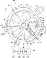
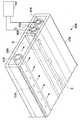
본 발명의 실시 형태에 의한 성막 장치(300)는 도 1(도 3의 B-B선을 따른 단면도)에 도시한 바와 같이 평면 형상이 대략 원형인 편평한 진공 용기(1)와, 이 진공 용기(1) 내에 설치되어, 당해 진공 용기(1)의 중심에 회전 중심을 갖는 서셉터(2)를 구비하고 있다. 진공 용기(1)는 천장판(11)을 용기 본체(12)로부터 분리할 수 있도록 구성되어 있다. 천장판(11)은, 예를 들어 O링 등의 밀봉 부재(13)를 통해 용기 본체(12)에 설치되고, 이에 의해 진공 용기(1)가 기밀하게 밀폐된다. 한편, 천장판(11)을 용기 본체(12)로부터 분리할 필요가 있을 때에는, 도시하지 않은 구동 기구에 의해 상방으로 들어 올려진다. 천장판(11) 및 용기 본체(12)는, 예를 들어 알루미늄(Al)으로 제작할 수 있다.The
서셉터(2)는, 본 실시 형태에 있어서는 약 20㎜의 두께를 갖는 카본판으로 제작되어, 약 960㎜의 직경을 갖는 원판 형상으로 형성되어 있다. 또한, 서셉터(2)의 상면, 이면 및 측면을 SiC로 코팅해도 좋다. 도 1을 참조하면, 서셉터(2)는 중앙에 원형의 개구부를 갖고 있고, 개구부의 주위에서 원통 형상의 코어부(21)에 의해 상하로부터 끼워져 보유 지지되어 있다. 코어부(21)는 연직 방향으로 신장되는 회전축(22)의 상단부에 고정되어 있다. 회전축(22)은 용기 본체(12)의 저 면부(14)를 관통하여, 그 하단부가 당해 회전축(22)을 연직축 주위로(예를 들어, 도 2에 도시한 바와 같이 회전 방향 RD로) 회전시키는 구동부(23)에 설치되어 있다. 이 구성에 의해, 서셉터(2)는 그 중심을 축으로 회전할 수 있다. 또한, 회전축(22) 및 구동부(23)는 상면이 개방된 통 형상의 케이스체(20) 내에 수납되어 있다. 이 케이스체(20)는 그 상면에 설치된 플랜지 부분(20a)을 통해 진공 용기(1)의 저면부(14)의 하면에 기밀하게 설치되어 있고, 이에 의해, 케이스체(20)의 내부 분위기가 외부 분위기로부터 격리되어 있다.In the present embodiment, the
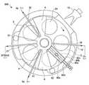
도 2 및 도 3에 도시한 바와 같이, 서셉터(2)의 상면에, 각각 웨이퍼(W)가 적재되는 복수(도시한 예에서는 5개)의 원형 오목부 형상의 적재부(24)가 형성되어 있다. 단, 도 3에서는 웨이퍼(W)를 1매만 도시하고 있다. 적재부(24)는 서셉터(2) 상에 서로 약 72°의 각도 간격으로 배치되어 있다.As shown in Figs. 2 and 3, on the top surface of the
도 4의 (a)를 참조하면, 적재부(24)와 적재부(24)에 적재된 웨이퍼(W)의 단면이 도시되어 있다. 이 도면에 도시한 바와 같이, 적재부(24)는 웨이퍼(W)의 직경보다도 약간 큰, 예를 들어 4㎜ 큰 직경과, 웨이퍼(W)의 두께와 동등한 깊이를 갖고 있다. 따라서, 웨이퍼(W)가 적재부(24)에 적재되었을 때, 웨이퍼(W)의 표면은 서셉터(2)의 적재부(24)를 제외한 영역의 표면과 동일한 높이에 있다. 가령, 웨이퍼(W)와 그 영역 사이에 비교적 큰 단차가 있으면, 그 단차에 의해 가스의 흐름에 난류가 발생하여, 웨이퍼(W) 상에서의 막 두께 균일성이 영향을 받는다. 이로 인해, 2개의 표면이 동일한 높이에 있다. 「동일한 높이」는, 여기서는 높이의 차가 약 5㎜ 이하인 것을 의미하지만, 그 차는 가공 정밀도가 허용되는 범위에서 가능한 한 제로에 가깝게 해야 한다.Referring to Fig. 4 (a), a cross section of the wafer W loaded on the
용기 본체(12)의 측벽에는, 도 2, 도 3 및 도 9에 도시한 바와 같이 반송구(15)가 형성되어 있다. 웨이퍼(W)는 반송구(15)를 통해 반송 아암(10)에 의해 진공 용기(1) 속으로(도 9), 또는 진공 용기(1)로부터 외부로 반송된다. 이 반송구(15)에는 게이트 밸브(도시하지 않음)가 설치되고, 이에 의해 반송구(15)가 개폐된다.On the side wall of the
도 2 및 도 3을 참조하면, 서셉터(2)의 상방에 제1 반응 가스 공급 노즐(31), 제2 반응 가스 공급 노즐(32) 및 분리 가스 공급 노즐(41, 42)이 설치되고, 이들은 소정의 각도 간격으로 반경 방향으로 연장되어 있다. 이 구성에 의해, 적재부(24)는 노즐(31, 32, 41 및 42)의 아래를 통과할 수 있다. 도시한 예에서는, 제2 반응 가스 공급 노즐(32), 분리 가스 공급 노즐(41), 제1 반응 가스 공급 노즐(31) 및 분리 가스 공급 노즐(42)이 이 순서대로 시계 방향으로 배치되어 있다. 이들 가스 노즐(31, 32, 41, 42)은 용기 본체(12)의 주위벽부를 관통하여, 가스 도입 포트(31a, 32a, 41a, 42a)인 단부를 용기 본체(12)의 외주벽에 설치함으로써, 지지되어 있다. 가스 노즐(31, 32, 41, 42)은, 도시한 예에서는 진공 용기(1)의 주위벽부로부터 진공 용기(1) 내로 도입되어 있지만, 환상의 돌출부(5)(후술)로부터 도입해도 좋다. 이 경우, 돌출부(5)의 외주면과 천장판(11)의 외표면으로 개방되는 L자형의 도관을 설치하여, 진공 용기(1) 내부에서 L자형의 도관의 한쪽의 개구에 가스 노즐[31(32, 41, 42)]을 접속하고, 진공 용기(1)의 외부에서 L자형의 도관의 다른 쪽의 개구에 가스 도입 포트[31a(32a, 41a, 42a)]를 접속할 수 있다.2 and 3, a first reaction
도시하고 있지 않지만, 반응 가스 공급 노즐(31)은 제1 반응 가스인 비스터셜부틸아미노실란(BTBAS)의 가스 공급원에 접속되고, 반응 가스 공급 노즐(32)은 제2 반응 가스인 오존(O3)의 가스 공급원에 접속되어 있다.Although not shown, the reaction
반응 가스 공급 노즐(31, 32)에는 하방측으로 반응 가스를 토출하기 위한 토출 구멍(33)이 노즐의 길이 방향으로 간격을 두고 배열되어 있다. 본 실시 형태에 있어서는, 토출 구멍(33)은 약 0.5㎜의 구경을 갖고, 반응 가스 공급 노즐(31, 32)의 길이 방향을 따라서 약 10㎜의 간격으로 배열되어 있다. 또한, 반응 가스 공급 노즐(31)의 하방 영역은 BTBAS 가스를 웨이퍼에 흡착시키기 위한 제1 처리 영역(P1)이고, 반응 가스 공급 노즐(32)의 하방 영역은 O3 가스를 웨이퍼에 흡착시키기 위한 제2 처리 영역(P2)이다.
한편, 분리 가스 공급 노즐(41, 42)은 질소 가스(N2)의 가스 공급원(도시하지 않음)에 접속되어 있다. 분리 가스 공급 노즐(41, 42)은 하방측으로 분리 가스를 토출하기 위한 토출 구멍(40)을 갖고 있다. 토출 구멍(40)은 길이 방향으로 소정의 간격으로 배치되어 있다. 본 실시 형태에 있어서는, 토출 구멍(40)은 약 0.5㎜의 구경을 갖고, 분리 가스 공급 노즐(41, 42)의 길이 방향을 따라서 약 10㎜의 간격으로 배열되어 있다.On the other hand, the separation
분리 가스 공급 노즐(41, 42)은 제1 처리 영역(P1)과 제2 처리 영역(P2)을 분리하도록 구성되는 분리 영역(D)에 설치되어 있다. 각 분리 영역(D)에 있어서는, 진공 용기(1)의 천장판(11)에, 도 2 내지 도 4에 도시한 바와 같이 볼록 형상 부(4)가 형성되어 있다. 볼록 형상부(4)는 부채형의 상면 형상을 갖고 있고, 그 정상부는 진공 용기(1)의 중심에 위치하고, 원호는 용기 본체(12)의 내주벽의 근방을 따라서 위치하고 있다. 또한, 볼록 형상부(4)는 볼록 형상부(4)가 2분할되도록 반경 방향으로 신장되는 홈부(43)를 갖고 있다. 홈부(43)에는 분리 가스 공급 노즐[41(42)]이 수용되어 있다. 분리 가스 공급 노즐[41(42)]의 중심축과 부채형의 볼록 형상부(4)의 한쪽의 변과의 사이의 거리는 분리 가스 공급 노즐[41(42)]의 중심축과 부채형의 볼록 형상부(4)의 다른 쪽의 변과의 사이의 거리와 거의 동등하다. 또한, 홈부(43)는, 본 실시 형태에서는 볼록 형상부(4)를 이등분하도록 형성되지만, 다른 실시 형태에 있어서는, 예를 들어 볼록 형상부(4)에 있어서의 서셉터(2)의 회전 방향 상류측이 넓어지도록 홈부(43)를 형성해도 좋다.The separation
상기한 구성에 따르면, 도 4의 (a)에 도시한 바와 같이, 분리 가스 공급 노즐[41(42)]의 양측에는 평탄한 낮은 천장면(44)(제1 천장면)이 있고, 낮은 천장면(44)의 양측에는 높은 천장면(45)(제2 천장면)이 있다. 볼록 형상부(4)[천장면(44)]는 제1 및 제2 반응 가스가 볼록 형상부(4)와 서셉터(2) 사이에 침입하는 것을 저지하여 혼합하는 것을 저지하기 위한 협애한 공간인 분리 공간을 형성한다.4 (a), there are flat low-ceiling scenes 44 (first ceiling scenes) on both sides of the separation gas supply nozzles 41 (42), and low- There are a high ceiling scene 45 (second ceiling scene) on both sides of the
도 4의 (b)를 참조하면, 서셉터(2)의 회전 방향을 따라서 반응 가스 공급 노즐(32)로부터 볼록 형상부(4)를 향해 흐르는 O3 가스가 당해 공간으로 침입하는 것이 저지되고, 또한 서셉터(2)의 회전 방향과 반대 방향을 따라서 반응 가스 공급 노즐(31)로부터 볼록 형상부(4)를 향해 흐르는 BTBAS 가스가 당해 공간으로 침입하 는 것이 저지된다. 「가스가 침입하는 것이 저지된다」는 것은, 분리 가스 공급 노즐(41)로부터 토출된 분리 가스인 N2 가스가 제1 천장면(44)과 서셉터(2)의 표면 사이에 확산되어, 본 예에서는 당해 제1 천장면(44)에 인접하는 제2 천장면(45)의 하방측의 공간으로 분출되어, 이에 의해 제2 천장면(45)의 하방측 공간으로부터의 가스가 침입할 수 없게 되는 것을 의미한다. 그리고, 「가스가 침입할 수 없게 된다」는 것은, 제2 천장면(45)의 하방측 공간으로부터 볼록 형상부(4)의 하방측 공간으로 전혀 들어갈 수 없는 경우만을 의미하는 것이 아니라, 반응 가스의 일부가 침입해도, 그 반응 가스가 분리 가스 공급 노즐(41)을 향해 더 진행할 수 없고, 따라서 혼합될 수 없는 것도 의미한다. 즉, 이와 같은 작용이 얻어지는 한, 분리 영역(D)은 제1 처리 영역(P1)과 제2 처리 영역(P2)을 분리하게 된다. 또한, 웨이퍼에 흡착한 가스에 대해서는 당연히 분리 영역(D) 내를 통과할 수 있다. 따라서, 가스의 침입 저지는 기상 중의 가스를 의미하고 있다.4B, O3 gas flowing from the reaction
다시 도 1을 참조하면, 진공 용기(1) 내의 높은 천장면(45)에 클리닝 노즐(60)이 설치되어 있다. 천장판(11)의 천장에는 개구(11a)가 형성되어 있고, 개구(11a)를 통해 클리닝 노즐(60)의 배기관(60a)이 외부로 돌출되어 있다. 따라서, 진공 용기(1)[천장판(11)]의 상면도인 도 5의 (a)에는 배기관(60a)이 도시되어 있다. 배기관(60a)은, 예를 들어, 후술하는 배기관(63)에 합류하여 진공 펌프(64)에 연결되어 있다.Referring again to FIG. 1, a cleaning
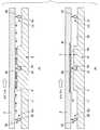
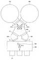
이하, 도 5의 (a)의 I-I선을 따른 단면도에 상당하는 도 5의 (b)를 참조하면 서, 클리닝 노즐(60)에 대해 설명한다. 도 5의 (b)에 도시한 바와 같이, 배기관(60a)은 O링 등의 시일 부재(R)를 통해 천장판(11)의 개구(11a)에 대해 기밀하게 고정되어 있다. 배기관(60a)의 하단부에는 외측 후드(hood) 부재(60b)가 접속되어 있다. 외측 후드 부재(60b)는, 도 5의 (b)에 도시한 바와 같이, 역오목 형상의 형상을 갖고, 서셉터(2)를 향해 개방되어 있다. 또한, 외측 후드 부재(60b)는, 도 2 및 도 3에 도시한 바와 같이 대략 서셉터(2)의 반경 방향을 따라서, 돌출부(5)(후술)로부터 서셉터(2)의 외주 단부까지 연장되어 있다. 환언하면, 외측 후드 부재(60b)는 돌출부(5)로부터 서셉터(2)의 외주 단부까지 연장되는 중공의 직육면체의 6면 중, 서셉터(2)에 면하는 면을 제거함으로써 얻어지는 형상을 갖고 있다. 또한, 외측 후드 부재(60b)는, 예를 들어 석영 유리나 알루미나로 제작할 수 있다.Hereinafter, the cleaning
도 5의 (b)에 도시한 바와 같이, 외측 후드 부재(60b)의 내측에는 내측 후드 부재(60c)가 배치되고, 외측 후드 부재(60b)와 내측 후드 부재(60c) 사이에는 공간이 형성되어 있다. 내측 후드 부재(60c)는 외측 후드 부재(60b)와 마찬가지로, 역오목 형상의 형상을 갖고, 서셉터(2)를 향해 개방되어 있다. 또한, 내측 후드 부재(60c)는 대략 서셉터(2)의 반경 방향을 따라서 연장되어 있고, 그 길이는 외측 후드 부재(60b)와 대략 동등하거나 또는 약간 짧아도 좋다. 또한, 내측 후드 부재(60c)는, 예를 들어 석영 유리로 제작할 수 있다.An
내측 후드 부재(60c)와 서셉터(2)의 상면으로 대략 둘러싸이는 역오목 형상의 공간에는 가스 노즐(60d, 60e)이 배치되어 있다. 가스 노즐(60d, 60e)은 서셉터(2)의 상면과 평행하고, 또한 내측 후드 부재(60c)의 길이 방향을 따라서 연장되 어 있다. 가스 노즐(60d, 60e)은, 예를 들어 석영 유리로 제작할 수 있다. 또한, 가스 노즐(60d)에는 가스 노즐(60e)의 방향으로 개방되는 복수의 구멍(60f)이 길이 방향을 따라서 형성되고, 가스 노즐(60e)에는 가스 노즐(60d)의 방향으로 개방되는 복수의 구멍(60g)이 길이 방향을 따라서 형성되어 있다. 구멍(60f, 60g)의 내경은, 예를 들어 약 0.5㎜로 할 수 있고, 그 간격은, 예를 들어 약 10㎜로 할 수 있다.
또한, 가스 노즐(60d, 60e)은, 도 2 및 도 3에 도시한 바와 같이, 반응 가스 공급 노즐(31, 32)과 마찬가지로, 용기 본체(12)의 주위벽부를 관통하여, 가스 도입 포트인 단부를 외주벽에 설치함으로써 지지되어 있다. 또한, 가스 노즐(60d, 60e)의 가스 도입 포트는 소정의 가스 공급부(도시하지 않음)와 접속되어 있다. 가스 공급부는 소정의 클리닝 가스를 저류하는 가스 실린더 등을 갖고, 이것으로부터, 가스 노즐(60d, 60e)로 클리닝 가스를 공급한다. 또한, 가스 공급부와 가스 노즐(60d, 60e) 사이의 배관에는, 예를 들어 질량 유량 제어기(MFC) 등의 유량 제어기가 설치되고, 이에 의해, 유량 제어된 클리닝 가스가 가스 노즐(60d, 60e)로 공급된다.2 and 3, like the reaction
또한, 클리닝 가스에는, 예를 들어 불화수소 가스와 같이, 그것만으로 반응성(에칭성 또는 부식성)을 갖는 가스뿐만 아니라, 그 자체는 반응성을 갖지 않지만 다른 가스와 화합함으로써 반응성을 갖는 가스를 발생시키는 가스도 포함된다.The cleaning gas includes not only a gas having reactivity (etchability or corrosiveness) only as a hydrogen fluoride gas, but also a gas capable of generating a gas having reactivity by itself, for example, .
본 실시 형태에 있어서는, 가스 노즐(60d)로부터 불소(F2) 가스가 공급되고, 가스 노즐(60e)로부터 수소(H2) 가스가 공급되도록, 가스 공급부, 배관 및 유량 제어기 등이 구성되어 있다.In the present embodiment, a gas supply unit, a pipe, a flow rate controller, and the like are configured so that fluorine (F2 ) gas is supplied from the
클리닝 노즐(60)의 작용에 대해서는, 본 발명의 실시 형태에 의한, 클리닝 노즐(60)을 사용한 클리닝 방법과 함께 후술한다.The operation of the cleaning
도 1, 도 2 및 도 3을 참조하면, 천장판(11)의 하면에는 내주연이 코어부(21)의 외주면에 면하도록 배치된 환상의 돌출부(5)가 형성되어 있다. 돌출부(5)는 코어부(21)보다도 외측의 영역에 있어서 서셉터(2)와 대향하고 있다. 또한, 돌출부(5)는 볼록 형상부(4)와 일체로 형성되어, 볼록 형상부(4)의 하면과 돌출부(5)의 하면은 하나의 평면을 형성하고 있다. 즉, 돌출부(5)의 하면의 서셉터(2)로부터의 높이는 볼록 형상부(4)의 하면[천장면(44)]의 높이와 동등하다. 이 높이는, 후에 높이(h)로 언급된다. 단, 돌출부(5)와 볼록 형상부(4)는 반드시 일체가 아니라도 좋고, 별체라도 좋다. 또한, 도 2 및 도 3은 볼록 형상부(4)를 진공 용기(1) 내에 남긴 채 천장판(11)을 제거한 진공 용기(1)의 내부 구성을 도시하고 있다.1, 2, and 3, an
본 실시 형태에 있어서는, 분리 영역(D)은 볼록 형상부(4)로 될 부채형 플레이트에 홈부(43)를 형성하고, 분리 가스 공급 노즐[41(42)]을 홈부(43)에 배치함으로써 형성된다. 그러나, 2개의 부채형 플레이트가 분리 가스 공급 노즐[41(42)]의 양측에 배치되도록, 이들 2개의 부채형 플레이트를 천장판(11)의 하면에 나사로 설치하도록 해도 좋다.In this embodiment, the separation area D is formed by forming the
본 실시 형태에 있어서, 약 300㎜의 직경을 갖는 웨이퍼(W)가 진공 용기(1) 내에서 처리되게 되는 경우, 볼록 형상부(4)는 서셉터의 회전 중심으로부터 140㎜ 이격된 내측의 원호(li)(도 3)에 따른, 예를 들어 140㎜의 둘레 방향 길이와, 서셉터(2)의 적재부(24)의 최외부에 대응하는 외측의 원호(lo)(도 3)에 따른, 예를 들어 502㎜의 둘레 방향 길이를 갖는다. 또한, 외측의 원호(lo)에 따른, 볼록 형상부(4)의 하나의 측벽으로부터 홈부(43)의 바로 근처의 측벽까지의 둘레 방향 길이는 약 246㎜이다.In the present embodiment, when the wafer W having a diameter of about 300 mm is to be processed in the
또한, 볼록 형상부(4)의 하면, 즉 천장면(44)의, 서셉터(2)의 표면으로부터 측정한 높이(h)[도 4의 (a)]는, 예를 들어 약 0.5㎜ 내지 약 10㎜이면 좋고, 약 4㎜이면 적합하다. 또한, 서셉터(2)의 회전수는, 예를 들어 1rpm 내지 500rpm으로 설정되어 있다. 분리 영역(D)의 분리 기능을 확보하기 위해서는, 처리 진공 용기(1) 내의 압력이나 서셉터(2)의 회전수 등에 따라서, 볼록 형상부(4)의 크기나 볼록 형상부(4)의 하면[제1 천장면(44)]과 서셉터(2)의 표면과의 높이(h)를, 예를 들어 실험 등을 통해 설정해도 좋다. 또한 분리 가스로서는, 본 실시 형태에서는 N2 가스이지만, 분리 가스가 산화 실리콘의 성막에 영향을 미치지 않는 한에 있어서, He나 Ar 가스 등의 불활성 가스나 수소 가스 등이라도 좋다.The height h (Fig. 4 (a)) measured from the surface of the
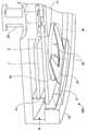
도 6은 도 3의 A-A선에 따른 단면도의 절반을 도시하고, 여기에는 볼록 형상부(4)와, 볼록 형상부(4)와 일체로 형성된 돌출부(5)가 도시되어 있다. 도 6을 참조하면, 볼록 형상부(4)는 그 외측 테두리에 있어서 L자 형상으로 굴곡되는 굴곡 부(46)를 갖고 있다. 볼록 형상부(4)는 천장판(11)에 설치되어 천장판(11)과 함께 용기 본체(12)로부터 분리될 수 있으므로, 굴곡부(46)와 서셉터(2) 사이 및 굴곡부(46)와 용기 본체(12) 사이에 약간의 간극이 있지만, 굴곡부(46)는 서셉터(2)와 용기 본체(12) 사이의 공간을 대략 메우고 있어, 반응 가스 공급 노즐(31a)로부터의 제1 반응 가스(BTBAS)와 반응 가스 공급 노즐(32a)로부터의 제2 반응 가스(오존)가 이 간극을 통해 혼합되는 것을 방지한다. 굴곡부(46)와 용기 본체(12) 사이의 간극 및 굴곡부(46)와 서셉터(2) 사이에 약간의 간극은 상술한 서셉터로부터 볼록 형상부(4)의 천장면(44)까지의 높이(h)와 대략 동일한 치수로 되어 있다. 도시한 예에 있어서, 굴곡부(46)의 서셉터(2)의 외주면에 면하는 측벽이 분리 영역(D)의 내주벽을 구성하고 있다.Fig. 6 shows half of a sectional view taken along the line A-A in Fig. 3, in which the
도 3에 도시하는 B-B선에 따른 단면도인 도 1을 다시 참조하면, 용기 본체(12)는 서셉터(2)의 외주면에 대향하는 용기 본체(12)의 내주부에 오목부를 갖고 있다. 이후, 이 오목부를 배기 영역(6)이라고 칭한다. 배기 영역(6)의 하방에는 배기구(61)[다른 배기구(62)에 대해서는 도 3 참조]가 형성되고, 이들에는 다른 배기구(62)에 대해서도 사용될 수 있는 배기관(63)을 통해 진공 펌프(64)에 접속되어 있다. 또한, 배기관(63)에는 압력 조정기(65)가 설치되어 있다. 복수의 압력 조정기(65)를, 대응하는 배기구(61, 62)에 대해 설치해도 좋다.Referring again to Fig. 1, which is a cross-sectional view taken along the line B-B in Fig. 3, the
도 3을 다시 참조하면, 배기구(61)는 상방으로부터 볼 때, 제1 반응 가스 공급 노즐(31)과, 제1 반응 가스 공급 노즐(31)에 대해 서셉터(2)의 시계 회전 방향의 하류에 위치하는 볼록 형상부(4)와의 사이에 배치되어 있다. 이 구성에 의해, 배기구(61)는 실질적으로 제1 반응 가스 공급 노즐(31)로부터의 BTBAS 가스만을 배기할 수 있다. 한편, 배기구(62)는 상방으로부터 볼 때, 제2 반응 가스 공급 노즐(32)과, 제2 반응 가스 공급 노즐(32)에 대해 서셉터(2)의 시계 회전 방향의 하류에 위치하는 볼록 형상부(4)와의 사이에 배치되어 있다. 이 구성에 의해, 배기구(62)는 실질적으로 제2 반응 가스 공급 노즐(32)로부터의 O3 가스만을 배기할 수 있다. 따라서, 이와 같이 구성되는 배기구(61, 62)는 분리 영역(D)이 BTBAS 가스와 O3 가스가 혼합되는 것을 방지하는 것을 보조할 수 있다.3, the
본 실시 형태에서는, 2개의 배기구가 용기 본체(12)에 형성되어 있지만, 다른 실시 형태에서는 3개의 배기구가 형성되어도 좋다. 예를 들어, 제2 반응 가스 공급 노즐(32)과, 제2 반응 가스 공급 노즐(32)에 대해 서셉터(2)의 시계 회전 방향의 상류에 위치하는 분리 영역(D)과의 사이에 추가의 배기구를 형성해도 좋다. 또한, 추가의 배기구를 어딘가에 형성해도 좋다. 도시한 예에서는, 배기구(61, 62)는 서셉터(2)보다도 낮은 위치에 형성함으로써 진공 용기(1)의 내주벽과 서셉터(2)의 주연 사이의 간극으로부터 배기하도록 하고 있지만, 용기 본체(12)의 측벽에 형성해도 좋다. 또한, 배기구(61, 62)를 용기 본체(12)의 측벽에 형성하는 경우, 배기구(61, 62)는 서셉터(2)보다도 높게 위치해도 좋다. 이 경우, 가스는 서셉터(2)의 표면을 따라서 흘러, 서셉터(2)의 표면보다 높게 위치하는 배기구(61, 62)로 유입된다. 따라서, 진공 용기(1) 내의 파티클이 불어 올려지지 않는다는 점에서, 배기구가, 예를 들어 천장판(11)에 형성된 경우에 비해, 유리하다.Although two exhaust ports are formed in the
도 1, 도 2 및 도 7에 도시한 바와 같이, 서셉터(2)와 용기 본체(12)의 저부(14) 사이의 공간에는 가열부로서의 환상의 히터 유닛(7)이 설치되고, 이에 의해, 서셉터(2) 상의 웨이퍼(W)가 서셉터(2)를 통해 프로세스 레시피에서 결정된 온도로 가열된다. 또한, 커버 부재(71)가 서셉터(2)의 하방에 있어서 서셉터(2)의 외주 근처에, 히터 유닛(7)을 둘러싸도록 설치되므로, 히터 유닛(7)이 놓여져 있는 공간이 히터 유닛(7)의 외측의 영역으로부터 구획되어 있다. 커버 부재(71)는 상단부에 플랜지부(71a)를 갖고, 플랜지부(71a)는 커버 부재(71) 내로 가스가 유입되는 것을 방지하기 위해, 서셉터(2)의 하면과 플랜지부 사이에 약간의 간극이 유지되도록 배치된다.1, 2, and 7, an
다시 도 1을 참조하면, 저부(14)는 환상의 히터 유닛(7)의 내측에 융기부를 갖고 있다. 융기부의 상면은 서셉터(2) 및 코어부(21)에 접근되어 있고, 융기부의 상면과 서셉터(2) 사이 및 융기부의 상면과 코어부(21)의 이면 사이에 약간의 간극을 남기고 있다. 또한, 저부(14)는 회전축(22)이 빠져나가는 중심 구멍을 갖고 있다. 이 중심 구멍의 내경은 회전축(22)의 직경보다도 약간 커서, 플랜지부(20a)를 통해 케이스체(20)와 연통하는 간극을 남기고 있다. 퍼지 가스 공급관(72)이 플랜지부(20a)의 상부에 접속되어 있다. 또한, 히터 유닛(7)이 수용되는 영역을 퍼지하기 위해, 복수의 퍼지 가스 공급관(73)이 소정의 각도 간격으로 히터 유닛(7)의 하방의 영역에 접속되어 있다.Referring back to Fig. 1, the
이와 같은 구성에 의해, 회전축(22)과 저부(14)의 중심 구멍 사이의 간극, 코어부(21)와 저부(14)의 융기부 사이의 간극 및 저부(14)의 융기부와 서셉터(2)의 이면 사이의 간극을 통해, 퍼지 가스 공급관(72)으로부터 히터 유닛 공간으로 N2 퍼지 가스가 흐른다. 또한, 퍼지 가스 공급관(73)으로부터 히터 유닛(7)의 아래의 공간으로 N2 가스가 흐른다. 그리고, 이들 N2 퍼지 가스는 커버 부재(71)의 플랜지부(71a)와 서셉터(2)의 이면 사이의 간극을 통해 배기구(61)로 유입된다. N2 퍼지 가스의 이와 같은 흐름은, 도 8에 화살표로 나타내고 있다. N2 퍼지 가스는 제1(제2) 반응 가스가 서셉터(2)의 하방의 공간을 돌아 흘러가 제2(제1) 반응 가스와 혼합되는 것을 방지하는 분리 가스로서 작용한다.With such a configuration, the clearance between the
도 8을 참조하면, 진공 용기(1)의 천장판(11)의 중심부에는 분리 가스 공급관(51)이 접속되고, 이에 의해, 천장판(11)과 코어부(21) 사이의 공간(52)에 분리 가스인 N2 가스가 공급된다. 이 공간(52)에 공급된 분리 가스는 돌출부(5)와 서셉터(2)의 좁은 간극(50)을 통해, 서셉터(2)의 표면을 따라서 흘러, 배기 영역(6)에 도달한다. 이 공간(52)과 간극(50)은 분리 가스가 가득 차 있으므로, 서셉터(2)의 중심부를 통해 반응 가스(BTBAS, O3)가 혼합되는 일이 없다. 즉, 본 실시 형태의 성막 장치(300)는 제1 처리 영역(P1)과 제2 처리 영역(P2)을 분리하기 위해 서셉터(2)의 회전 중심부와 진공 용기(1)에 의해 구획되어, 분리 가스를 서셉터(2)의 상면을 향해 토출하는 토출 구멍을 갖도록 구성되는 중심 영역(C)이 형성되어 있다. 또한, 도시한 예에서는, 토출 구멍은 돌출부(5)와 서셉터(2)의 좁은 간극(50)에 상당한다.8, a separation
또한, 본 실시 형태에 의한 성막 장치(300)에는 장치 전체의 동작의 컨트롤을 행하기 위한 제어부(100)가 설치되어 있다. 이 제어부(100)는, 예를 들어 컴퓨터로 구성되는 프로세스 컨트롤러(100a)와, 유저 인터페이스부(100b)와, 메모리 장치(100c)를 갖는다. 유저 인터페이스부(100b)는 성막 장치(300)의 동작 상황을 표시하는 디스플레이나, 성막 장치(300)의 조작자가 프로세스 레시피를 선택하거나, 프로세스 관리자가 프로세스 레시피의 파라미터를 변경하기 위한 키보드나 터치 패널(도시하지 않음) 등을 갖는다.In addition, the
메모리 장치(100c)는 프로세스 컨트롤러(100a)에 다양한 프로세스를 실시시키는 제어 프로그램, 프로세스 레시피 및 각종 프로세스에 있어서의 파라미터 등을 기억하고 있다. 또한, 이들 프로그램에는, 예를 들어 후술하는 클리닝 방법을 행하게 하기 위한 스텝군을 갖고 있는 것이다. 이들의 제어 프로그램이나 프로세스 레시피는 유저 인터페이스부(100b)로부터의 지시에 따라서, 프로세스 컨트롤러(100a)에 의해 판독되어 실행된다. 또한, 이들 프로그램은 컴퓨터 판독 가능 기억 매체(100d)에 저장되고, 이들에 대응한 입출력 장치(도시하지 않음)를 통해 메모리 장치(100c)로 인스톨해도 좋다. 컴퓨터 판독 가능 기억 매체(100d)는 하드 디스크, CD, CD-R/RW, DVD-R/RW, 플렉시블 디스크, 반도체 메모리 등이라도 좋다. 또한, 프로그램은 통신 회선을 통해 메모리 장치(100c)로 다운로드해도 좋다.The
다음에, 본 실시 형태의 성막 장치(300)의 동작(성막 방법)에 대해 설명한다. 우선, 적재부(24)가 반송구(15)에 정렬하도록 서셉터(2)가 회전하여, 게이트 밸브(도시하지 않음)를 개방한다. 다음에, 반송 아암(10)에 의해 반송구(15)를 통 해 웨이퍼(W)를 용기(1)로 운반한다. 웨이퍼(W)는 승강 핀(16)에 의해 수취되어, 반송 아암(10)이 용기(1)로부터 빠져나간 후에, 승강 기구(도시하지 않음)에 의해 구동되는 승강 핀(16)에 의해 적재부(24)로 내려진다. 상기 일련의 동작이 5회 반복되어, 5매의 웨이퍼(W)가 서셉터(2)에 탑재된다. 계속해서, 진공 용기(1) 내가 진공 펌프(64) 및 압력 조정기(65)에 의해 미리 설정한 압력으로 유지된다. 서셉터(2)가 위에서 볼 때 시계 방향으로 회전을 개시한다. 서셉터(2)는 히터 유닛(7)에 의해 미리 소정의 온도(예를 들어, 300℃)로 가열되어 있어, 웨이퍼(W)가 이 서셉터(2)에 적재됨으로써 가열된다. 웨이퍼(W)가 가열되어, 소정의 온도로 유지된 것이 온도 센서(도시하지 않음)에 의해 확인된 후, 제1 반응 가스(BTBAS)가 제1 반응 가스 공급 노즐(31)을 통해 제1 처리 영역으로 공급되고, 제2 반응 가스(O3)가 제2 반응 가스 공급 노즐(32)을 통해 제2 처리 영역(P2)으로 공급된다. 또한, 분리 가스(N2)가 공급된다.Next, the operation (film forming method) of the
웨이퍼(W)가 제1 반응 가스 공급 노즐(31)의 하방의 제1 처리 영역(P1)을 통과할 때에, 웨이퍼(W)의 표면에 BTBAS 분자가 흡착하고, 제2 반응 가스 공급 노즐(32)의 하방의 제2 처리 영역(P2)을 통과할 때에, 웨이퍼(W)의 표면에 O3 분자가 흡착되어, O3에 의해 BTBAS 분자가 산화된다. 따라서, 웨이퍼(W)가 서셉터(2)의 회전에 의해, 영역(P1, P2)의 양쪽을 1회 통과하면, 웨이퍼(W)의 표면에 산화 실리콘의 1분자층이 형성된다. 계속해서, 웨이퍼(W)가 영역(P1, P2)을 교대로 복수회 통과하여, 소정의 막 두께를 갖는 산화 실리콘막이 웨이퍼(W)의 표면에 퇴적된다. 소정의 막 두께를 갖는 산화 실리콘막이 퇴적된 후, BTBAS 가스와 오존 가스를 정지하여, 서셉터(2)의 회전을 정지한다. 그리고, 웨이퍼(W)는 반입 동작과 역의 동작에 의해 순차적으로 반송 아암(10)에 의해 용기(1)로부터 반출된다.BTBAS molecules are adsorbed on the surface of the wafer W when the wafer W passes through the first process region P1 below the first reaction
또한, 상기한 성막 동작 중, 분리 가스 공급관(51)으로부터도 분리 가스인 N2 가스가 공급되고, 이에 의해 중심 영역(C)으로부터, 즉 돌출부(5)와 서셉터(2) 사이의 간극(50)으로부터 서셉터(2)의 표면을 따라서 N2 가스가 토출된다. 본 실시 형태에서는 제2 천장면(45)의 아래의 공간이며 반응 가스 공급 노즐[31(32)]이 배치되어 있는 공간은 중심 영역(C) 및 제1 천장면(44)과 서셉터(2) 사이의 협애한 공간보다도 낮은 압력을 갖고 있다. 이는, 천장면(45)의 아래의 공간에 인접하여 배기 영역(6)이 형성되고, 그 공간은 배기 영역(6)을 통해 직접적으로 배기되기 때문이다. 또한, 협애한 공간이 반응 가스 공급 노즐[31(32)]이 배치되어 있는 공간{또는 제1(제2) 처리 영역[P1(P2)]}과 협애한 공간 사이의 압력차가 높이(h)에 의해 유지될 수 있도록 형성되어 있기 때문이기도 하다.N2 gas, which is a separation gas, is also supplied from the separation
다음에, 가스 노즐(31, 32, 41, 42)로부터 진공 용기(1) 내로 공급된 가스의 플로우 패턴을 도 10을 참조하면서 설명한다. 도 10은 플로우 패턴을 모식적으로 도시하는 도면이다. 단, 도 10에 있어서, 클리닝 노즐(60)은 생략하고 있다. 도시한 바와 같이, 제2 반응 가스 공급 노즐(32)로부터 토출된 O3 가스의 일부는 서셉터(2)의 표면[및 웨이퍼(W)의 표면]에 부딪쳐, 그 표면을 따라서 서셉터(2)의 회전 방향과 역의 방향으로 흐른다. 계속해서, 이 O3 가스는 서셉터(2)의 회전 방향의 상류측으로부터 흘러 온 N2 가스에 되밀려져, 서셉터(2)의 주연과 진공 용기(1)의 내주벽측으로 방향을 바꾼다. 마지막으로, O3 가스는 배기 영역(6)으로 유입되어, 배기구(62)를 통해 진공 용기(1)로부터 배기된다.Next, a flow pattern of gas supplied from the
제2 반응 가스 공급 노즐(32)로부터 토출된 O3 가스의 다른 부분은 서셉터(2)의 표면[및 웨이퍼(W)의 표면]에 부딪쳐, 그 표면을 따라서 서셉터(2)의 회전 방향과 동일한 방향으로 흐른다. 이 부분의 O3 가스는, 주로 중심 영역(C)으로부터 흐르는 N2 가스와 배기구(62)를 통한 흡인력에 의해, 배기 영역(6)을 향해 흐른다. 한편, 이 부분의 O3 가스의 소량 부분이, 제2 반응 가스 공급 노즐(32)에 대해 서셉터(2)의 회전 방향의 하류측에 위치하는 분리 영역(D)을 향해 흘러, 천장면(44)과 서셉터(2) 사이의 간극으로 들어갈 가능성이 있다. 그러나, 그 간극의 높이(h)가 의도한 성막 조건 하에서 당해 간극으로의 유입을 저지할 정도의 높이로 설정되어 있으므로, O3 가스는 그 간극으로 들어가는 것이 저지된다. 가령, 소량의 O3 가스가 그 간극으로 유입되었다고 해도, 그 O3 가스는 분리 영역(D)의 안측까지 흐를 수 없다. 간극으로 유입된 소량의 O3 가스는 분리 가스 공급 노즐(41)로부터 토출된 분리 가스에 의해 되밀린다. 따라서, 도 10에 도시한 바와 같이, 서셉터(2)의 상면을 회전 방향을 따라서 흐르는 실질적으로 모든 O3 가스가, 배기 영역(6)으로 흘러 배기구(62)에 의해 배기된다.Another part of the O3 gas discharged from the second reaction
마찬가지로, 제1 반응 가스 공급 노즐(31)로부터 토출되어, 서셉터(2)의 회전 방향과 반대의 방향으로 서셉터(2)의 표면을 따라서 흐르는 일부의 BTBAS 가스는 제1 반응 가스 공급 노즐(31)에 대해 회전 방향 상류측에 위치하는 볼록 형상부(4)의 천장면(44)과 서셉터(2) 사이의 간극으로 유입되는 것이 방지된다. 가령 소량의 BTBAS 가스가 유입되었다고 해도, 분리 가스 공급 노즐(41)로부터 토출되는 N2 가스에 의해 되밀린다. 되밀린 BTBAS 가스는 분리 가스 공급 노즐(41)로부터의 N2 가스와 중심 영역(C)으로부터 토출되고 있는 N2 가스와 함께, 서셉터(2)의 외주연과 진공 용기(1)의 내주벽을 향해 흘러, 배기 영역(6)을 통해 배기구(61)를 통해 배기된다.Likewise, a part of the BTBAS gas that is discharged from the first reaction
제1 반응 가스 공급 노즐(31)로부터 하방측으로 토출되어, 서셉터(2)의 회전 방향과 동일 방향으로 서셉터(2)의 표면[및 웨이퍼(W)의 표면]을 따라서 흐르는 다른 부분의 BTBAS 가스는 제1 반응 가스 공급 노즐(31)에 대해 회전 방향 하류측에 위치하는 볼록 형상부(4)의 천장면(44)과 서셉터(2) 사이로 유입할 수 없다. 가령 소량의 BTBAS 가스가 유입되었다고 해도, 분리 가스 공급 노즐(42)로부터 토출되는 N2 가스에 의해 되밀린다. 되밀린 BTBAS 가스는 분리 영역(D)의 분리 가스 공급 노즐(42)로부터의 N2 가스와 중심 영역(C)으로부터 토출되고 있는 N2 가스와 함께, 배기 영역(6)을 향해 흘러, 배기구(61)에 의해 배기된다.The BTBAS of the other portion flowing along the surface of the susceptor 2 (and the surface of the wafer W) in the same direction as the rotation direction of the
상술한 바와 같이, 분리 영역(D)은 BTBAS 가스나 O3 가스가 분리 영역(D)으 로 유입되는 것을 방지하거나, 분리 영역(D)으로 유입되는 BTBAS 가스나 O3 가스의 양을 충분히 저감시키거나 또는, BTBAS 가스나 O3 가스를 되밀 수 있다. 웨이퍼(W)에 흡착한 BTBAS 분자와 O3 분자는 분리 영역(D)을 빠져나가는 것이 허용되어, 막의 퇴적에 기여한다.As described above, the separation region D prevents BTBAS gas or O3 gas from flowing into the separation region D, or sufficiently reduces the amount of BTBAS gas or O3 gas introduced into the separation region D Or BTBAS gas or O3 gas. The BTBAS molecules and O3 molecules adsorbed on the wafer W are allowed to escape from the separation region D and contribute to the deposition of the film.
또한, 도 8 및 도 10에 도시한 바와 같이, 중심 영역(C)으로부터는 분리 가스가 서셉터(2)의 외주연을 향해 토출되고 있으므로, 제1 처리 영역(P1)의 BTBAS 가스[제2 처리 영역(P2)의 O3 가스]는 중심 영역(C)으로 유입될 수 없다. 가령, 제1 처리 영역(P1)의 소량의 BTBAS[제2 처리 영역(P2)의 O3 가스]가 중심 영역(C)으로 유입되었다고 해도, 그 BTBAS 가스(O3 가스)는 N2 가스에 의해 되밀려, 제1 처리 영역(P1)의 BTBAS 가스[제2 처리 영역(P2)의 O3 가스]가 중심 영역(C)을 통해 제2 처리 영역(P2)[제1 처리 영역(P1)]으로 유입되는 것이 저지된다.8 and 10, since the separation gas is discharged toward the outer periphery of the
또한, 제1 처리 영역(P1)의 BTBAS 가스[제2 처리 영역(P2)의 O3 가스]는 서셉터(2)와 용기 본체(12)의 내주벽과의 사이의 공간을 통해 제2 처리 영역(P2)[제1 처리 영역(P1)]으로 유입되는 것도 저지된다. 이는, 굴곡부(46)가 볼록 형상부(4)로부터 하향으로 형성되고, 굴곡부(46)와 서셉터(2)의 간극 및 굴곡부(46)와 용기 본체(12)의 내주벽과의 사이의 간극이, 볼록 형상부(4)의 천장면(44)의 서셉터(2)로부터의 높이(h)와 동일할 정도로 작으므로, 2개의 처리 영역 사이의 연통을 실질적으로 회피하고 있기 때문이다. 따라서, BTBAS 가스는 배기구(61)로부터 배기되 고, O3 가스는 배기구(62)로부터 배기되어, 이들 2개의 반응 가스가 혼합되는 일은 없다. 또한, 서셉터(2)의 하방의 공간은 퍼지 가스 공급관(72, 73)으로부터 공급되는 N2 가스에 의해 퍼지되어 있다. 따라서, BTBAS 가스는 서셉터(2)의 하방을 통해 프로세스 영역(P2)으로 유입될 수는 없다.The BTBAS gas (O3 gas in the second processing region P2) of the first processing region P1 is supplied through the space between the
본 실시 형태에 의한 성막 장치(300)에 있어서의 적합한 프로세스 파라미터를 이하에 게재한다.Appropriate process parameters in the
ㆍ 서셉터(2)의 회전 속도 : 1-500rpm[웨이퍼(W)의 직경이 300㎜인 경우]- Rotation speed of the susceptor 2: 1-500 rpm (when the diameter of the wafer W is 300 mm)
ㆍ 진공 용기(1)의 압력 : 1067㎩(8Torr)Pressure of the vacuum container 1: 1067 Pa (8 Torr)
ㆍ 웨이퍼 온도 : 350℃ㆍ Wafer temperature: 350 ℃
ㆍ BTBAS 가스의 유량 : 100sccmㆍ Flow rate of BTBAS gas: 100 sccm
ㆍ O3 가스의 유량 : 10000sccmㆍ Flow rate of O3 gas: 10000 sccm
ㆍ 분리 가스 공급 노즐(41, 42)로부터의 N2 가스의 유량 : 20000sccmFlow rate of N2 gas from the separation
ㆍ 분리 가스 공급관(51)으로부터의 N2 가스의 유량 : 5000sccmFlow rate of N2 gas from the separation gas supply pipe 51: 5000 sccm
ㆍ 서셉터(2)의 회전수 : 600 회전(필요한 막두께에 의함)Rotation speed of susceptor 2: 600 rotations (depending on required film thickness)
본 실시 형태에 의한 성막 장치(300)에 따르면, 성막 장치(300)가, BTBAS 가스가 공급되는 제1 처리 영역과, O3 가스가 공급되는 제2 처리 영역 사이에, 낮은 천장면(44)을 포함하는 분리 영역(D)을 갖고 있으므로, BTBAS 가스(O3 가스)가 제2 처리 영역(P2)[제1 처리 영역(P1)]으로 유입되는 것이 방지되어, O3 가스(BTBAS 가 스)와 혼합되는 것이 방지된다. 따라서, 웨이퍼(W)가 적재된 서셉터(2)를 회전시켜, 웨이퍼(W)를 제1 처리 영역(P1), 분리 영역(D), 제2 처리 영역(P2) 및 분리 영역(D)을 통과시킴으로써, 산화 실리콘막의 분자층 성막이 확실하게 실시된다. 또한, BTBAS 가스(O3 가스)가 제2 처리 영역(P2)[제1 처리 영역(P1)]으로 유입되어 O3 가스(BTBAS 가스)와 혼합되는 것을 더욱 확실하게 방지하기 위해, 분리 영역(D)은 N2 가스를 토출하는 분리 가스 공급 노즐(41, 42)을 더 포함한다. 또한, 본 실시 형태에 의한 성막 장치(300)의 진공 용기(1)는 N2 가스가 토출되는 토출 구멍을 갖는 중심 영역(C)을 갖고 있으므로, 중심 영역(C)을 통해 BTBAS 가스(O3 가스)가 제2 처리 영역(P2)[제1 처리 영역(P1)]으로 유입되어 O3 가스(BTBAS 가스)와 혼합되는 것을 방지할 수 있다.According to the
상술한 바와 같이, 본 발명의 실시 형태에 의한 성막 장치(300)에 있어서는, 반응 가스가 기상 중에서 혼합되는 경우가 거의 없고, 따라서, 진공 용기(1)의 내벽면 등으로의 막의 퇴적을 최대한 저감시키는 것이 가능하다. 그러나, 서셉터(2)에는 제1 처리 영역(P1)을 통과할 때에 제1 반응 가스(예를 들어, BTBAS 가스)의 가스 분자 등이 흡착되고, 제2 처리 영역(P2)을 통과할 때에 제2 반응 가스(예를 들어, O3 가스)의 가스 분자 등이 흡착될 수 있으므로, 이들 반응 가스의 반응 생성물(상기한 예에서는 산화 실리콘)이 퇴적될 가능성이 있다. 서셉터(2)에 퇴적된 반응 생성 물질의 두께가 소정의 두께를 초과하면, 박리되어 파티클이 발생하게 되 지만, 본 발명의 실시 형태에 의한 성막 장치(300)에 있어서는, 클리닝 노즐(60)이 설치되어 있으므로, 이에 의해 퇴적된 반응 생성 물질을 제거하는 것이 가능하다. 이하, 클리닝 노즐(60)을 이용하여, 서셉터(2) 상에 퇴적된 산화 실리콘을 제거하는 클리닝 방법에 대해 설명한다. 또한, 이 클리닝 방법은, 예를 들어 성막 장치(300)에 있어서의 성막의 1런마다 행해도 좋고, 소정 횟수의 런 이후에 행해도 좋다. 또한, 이 클리닝 방법은 메모리 장치(100c)에 저장되어, 클리닝 방법을 실시하기 위해 성막 장치(300)의 각 부품 또는 부재를 적절하게 동작시키는 스텝군을 포함하는, 클리닝을 위한 프로그램이 프로세스 컨트롤러(100a)에 있어서 실행됨으로써, 성막 장치(300)에 있어서 실시된다.As described above, in the
우선, 분리 가스 공급 노즐(41 및 42)로부터 N2 가스를 흘리는 동시에, 진공 펌프(64) 및 압력 조정기(65)에 의해 진공 용기(1) 내가 소정의 압력으로 유지된다. 이 압력은, 예를 들어 133.3㎩ 내지 50㎪로 할 수 있다.The N2 gas isfirst flowed from the separation
다음에, 서셉터(2)를 회전시킨다. 회전수는 서셉터(2) 상의 산화 실리콘의 두께, 그 산화 실리콘의 제거 레이트(에칭 레이트) 및 클리닝 가스의 농도 등을 고려하여 설정할 수 있고, 예를 들어 10rpm 이하로 할 수 있다. 또한, 사용하는 클리닝 가스에 따라서는, 서셉터(2)를 소정의 온도로 가열해도 좋다.Next, the
계속해서, 클리닝 노즐(60)의 배기관(60a)을 통해 클리닝 노즐(60)의 내측의 공간을 배기하면서, 이 공간에 대해, 가스 공급부(도시하지 않음)로부터 가스 노즐(60d)을 통해 F2 가스를 공급하고, 가스 노즐(60e)을 통해 H2 가스를 공급한다. 이들 가스는, 내측 후드 부재(60c)의 내측의 공간(역오목 형상의 공간)에 있어서 기상 중에서 반응하여, 불산(HF)이 생성된다. 생성된 HF에 의해 서셉터(2)의 상면에 퇴적된 산화 실리콘이 분해되어 제거된다. 또한, HF와 산화 실리콘의 반응 생성물이나, 미반응의 HF, H2 및 F2 등의 가스는 외측 후드 부재(60b)와 내측 후드 부재(60c) 사이의 공간(가스 유로)과 배기관(60a)을 통해 배기된다. 또한, 이 가스 유로에는 비록 약간이기는 하나, 배기관(60a)을 통한 배기에 의해 외측 후드 부재(60b)의 외측으로부터 N2 가스가 유입된다. 이로 인해, HF나 F2 등의 반응성의 가스가 진공 용기(1) 내로 확산되는 경우는 거의 없다. 또한, 진공 용기(1) 내의 압력을 비교적 높게 하면, 클리닝 노즐(60)의 외측으로 클리닝 가스가 유출되는 것을 억제할 수 있는 점에서 유리하다. 환언하면, 클리닝 노즐(60) 내의 압력이 진공 용기(1) 내의 압력보다도 낮아지도록, 배기관(60a)을 통한 배기를 조정하면 바람직하다.Subsequently, while the space inside the cleaning
클리닝 가스를 흘린 후 소정의 시간(클리닝 시간)이 경과한 후, 가스 노즐(60d, 60e)로부터 가스의 공급을 정지하고, 진공 용기(1) 내의 퍼지를 행한다. 이 퍼지는 소정의 시간, 분리 가스 공급 노즐(41, 42)로부터 N2 가스를 계속해서 공급함으로써 행할 수 있다. 퍼지 종료 후, 서셉터(2)의 회전을 정지하여, N2 가스의 공급을 정지함으로써, 클리닝이 종료된다.After a predetermined period of time (cleaning time) has elapsed after flowing the cleaning gas, the supply of the gas from the
상술한 바와 같이, 본 발명의 실시 형태에 의한 성막 장치(300)에 있어서는, 서셉터(2)의 상면에 근접하여 클리닝 노즐(60)이 설치되고, 이것으로부터 서셉 터(2)의 상면으로 클리닝 가스가 제공되므로, 서셉터(2) 상의 퇴적물을 제거할 수 있다. 즉, 진공 용기(1)를 분해하지 않아도 서셉터(2) 상의 퇴적물을 제거할 수 있으므로, 턴 어라운드 타임(TAT)을 저감시킬 수 있다. 또한, 클리닝 노즐(60)은 가스 노즐(60d, 60e)로부터 공급되는 클리닝 가스가, 서셉터(2)의 상면에 도달한 후, 내측 후드 부재(60c)에 의해 구획되는 공간[가스 노즐(60d, 60e)이 연장되는 공간]의 양측으로 개방된 가스 유로로부터 배기되도록 구성되므로, 진공 용기(1) 내로 확산되는 일이 없다. 따라서, 클리닝 가스에 의해, 예를 들어 알루미늄과 같은 금속에 의해 제작되는 진공 용기(1)의 내면이 부식되는 등의 문제를 회피하는 것이 가능하다. 가령, 클리닝 노즐(60)이 없다고 하면, 클리닝 가스가 진공 용기(1) 내의 전체에 퍼지므로, 진공 용기(1)의 내면의 전체를 클리닝 가스로부터 보호하는 처치가 필요해지지만, 클리닝 노즐(60)에 따르면, 그와 같은 처치는 불필요해져, 메인터넌스 비용을 저감시킬 수 있다. 또한, 클리닝 가스를 내측 후드 부재(60c)에 의해 구획되는 공간에 머무르게 할 수 있으므로, 클리닝 가스의 농도를 비교적 높게 하는 것이 가능하다. 따라서, 클리닝의 효율을 높게 할 수 있어, 클리닝에 필요로 하는 시간의 단축을 통해, 제조 처리량의 향상에 공헌할 수 있다.As described above, in the
여기서, 클리닝 노즐(60)의 구성에 대해 추가의 설명을 한다. 외측 후드 부재(60b)의 개구 단부와 서셉터(2)의 상면 사이의 간극(G1)[도 5의 (b)]의 높이는, 예를 들어 약 1㎜ 이상 약 4㎜ 이하인 것이 바람직하다. 약 4㎜보다 높으면, 가스 노즐(60d, 60e)로부터 토출되는 클리닝 가스가 가스 유로로부터 배기되지 않아, 간극(G1)을 통해 진공 용기(1) 내로 확산되기 쉬워지고, 약 1㎜보다 낮으면, 외측 후 드 부재(60b)가 서셉터(2)의 상면에 접촉하여 파티클을 발생하기 때문이다.Here, the construction of the cleaning
또한, 외측 후드 부재(60b)와 내측 후드 부재(60c) 사이의 간격, 즉 이들 사이에 형성되는 공간(가스 유로)의 폭은, 예를 들어 약 5㎜ 내지 약 10㎜인 것이 바람직하다. 또한, 내측 후드 부재(60c)와 서셉터(2)의 상면 사이의 간극(G2)[도 5의 (b)]의 높이는, 예를 들어 약 2㎜ 내지 약 5㎜이면 좋다. 또한, 클리닝 가스를 가스 유로로 유입하기 쉽게 하기 위해, 간극(G2)의 높이 ≥ 간극(G1)의 높이 등의 관계를 갖고 있으면 바람직하다.It is preferable that the distance between the
또한, 본 실시 형태에 의한 성막 장치(300)에 있어서는, 서셉터(2)는 5개의 적재부(24)를 갖고, 대응하는 5개의 적재부(24)에 적재된 5매의 웨이퍼(W)를 1회의 런으로 처리할 수 있지만, 5개의 적재부(24) 중 하나에 1매의 웨이퍼(W)를 적재해도 좋고, 서셉터(2)에 적재부(24)를 하나만 형성해도 좋다.In the
또한, 산화 실리콘막의 분자층 성막으로 한정되지 않고, 성막 장치(300)에 의해 질화실리콘막의 분자층 성막을 행할 수도 있다. 질화실리콘막의 분자층 성막을 위한 질화가스로서는, 암모니아(NH3)나 히드라진(N2H2) 등을 이용할 수 있다.Further, the molecular film deposition of the silicon nitride film can be performed by the
또한, 산화 실리콘막이나 질화실리콘막의 분자층 성막을 위한 원료 가스로서는, BTBAS로 한정되지 않고, 디클로로실란(DCS), 헥사클로로디실란(HCD), 트리스디메틸아미노실란(3DMAS), 테트라에톡시실란(TEOS) 등을 이용할 수 있다.The raw material gas for forming the molecular layer of the silicon oxide film or the silicon nitride film is not limited to BTBAS but may be dichlorosilane (DCS), hexachlorodisilane (HCD), trisdimethylaminosilane (3DMAS), tetraethoxysilane (TEOS) or the like can be used.
또한, 본 발명의 실시 형태에 의한 성막 장치 및 성막 방법에 있어서는, 산화 실리콘막이나 질화실리콘막으로 한정되지 않고, 트리메틸알루미늄(TMA)과 O3 또 는 산소 플라즈마를 사용한 산화알루미늄(Al2O3)의 분자층 성막, 테트라키스에틸메틸아미노지르코늄(TEMAZ)과 O3 또는 산소 플라즈마를 사용한 산화지르코늄(ZrO2)의 분자층 성막, 테트라키스에틸메틸아미노하프늄(TEMAHf)과 O3 또는 산소 플라즈마를 사용한 산화하프늄(HfO2)의 분자층 성막, 스트론튬비스테트라메틸헵탄디오나토[Sr(THD)2]와 O3 또는 산소 플라즈마를 사용한 산화스트론튬(SrO)의 분자층 성막, 티타늄메틸펜탄디오나토비스테트라메틸헵탄디오나토[Ti(MPD)(THD)]와 O3 또는 산소 플라즈마를 사용한 산화티타늄(TiO)의 분자층 성막 등을 행할 수 있다.In addition, in the film forming apparatus and the film forming method according to the embodiment of the present invention, not only a silicon oxide film or a silicon nitride film but also aluminum oxide (Al2 O3) using trimethyl aluminum (TMA) and O3 or oxygen plasma ), Molecular layer deposition of zirconium oxide (ZrO2 ) using tetrakisethylmethylaminosilonium (TEMAZ) and O3 or oxygen plasma, tetrakisethylmethylaminoamin hafnium (TEMAHf) and O3 or oxygen plasma Molecular layer deposition of hafnium oxide (HfO2 ) used, molecular layer deposition of strontium bistetramethyl heptandionato [Sr (THD)2 ] and strontium oxide (SrO) using O3 or oxygen plasma, titanium methyl pentanedionatobis Molecular layer deposition of titanium oxide (TiO) using tetramethylheptanedionato [Ti (MPD) (THD)] and O3 or oxygen plasma can be performed.
서셉터(2)의 외주연에 가까울수록 큰 원심력이 작용하므로, 예를 들어 BTBAS 가스는 서셉터(2)의 외주연에 가까운 부분에 있어서, 큰 속도로 분리 영역(D)을 향한다. 따라서, 서셉터(2)의 외주연에 가까운 부분에서는 천장면(44)과 서셉터(2) 사이의 간극에 BTBAS 가스가 유입될 가능성이 높다. 따라서, 볼록 형상부(4)의 폭(회전 방향을 따른 길이)을 외주연을 향할수록 넓게 하면, BTBAS 가스가 그 간극으로 들어가기 어렵게 할 수 있다. 이 관점으로부터는, 본 실시 형태에 있어서 상술한 바와 같이, 볼록 형상부(4)가 부채형의 상면 형상을 가지면 바람직하다.The BTBAS gas is directed to the separation region D at a large rate at a portion near the outer periphery of the
이하에, 볼록 형상부(4)[또는 천장면(44)]의 사이즈를 다시 예시한다. 도 11의 (a) 및 도 11의 (b)를 참조하면, 분리 가스 공급 노즐[41(42)]의 양측에 협애한 공간을 형성하는 볼록 형상부(4)[천장면(44)]는 웨이퍼 중심(WO)이 지나는 경로에 대응하는 원호의 길이(L)로서 웨이퍼(W)의 직경의 약 1/10 내지 약 1/1의 길이 이면 좋고, 약 1/6 이상이면 바람직하다. 구체적으로는, 웨이퍼(W)가 300㎜의 직경을 갖고 있는 경우, 이 길이(L)는 약 50㎜ 이상이 바람직하다. 이 길이(L)가 짧은 경우, 천장면(44)과 서셉터(2) 사이의 협애한 공간의 높이(h)는 반응 가스가 협애한 공간으로 유입되는 것을 효과적으로 방지하기 위해, 낮게 해야만 한다. 그러나, 길이(L)가 지나치게 짧아지고, 높이(h)가 극단적으로 낮아지면, 서셉터(2)가 천장면(44)에 충돌하고, 파티클이 발생하여 웨이퍼의 오염이 발생하거나, 웨이퍼가 파손될 가능성이 있다. 따라서, 서셉터(2)가 천장면(44)에 충돌하는 것을 피하기 위해, 서셉터(2)의 진동을 억제하거나, 또는 서셉터(2)를 안정적으로 회전시키기 위한 방책이 필요해진다. 한편, 길이(L)를 짧게 한 채로 협애한 공간의 높이(h)를 비교적 크게 유지하는 경우에는, 천장면(44)과 서셉터(2) 사이의 협애한 공간으로 반응 가스가 유입되는 것을 방지하기 위해, 서셉터(2)의 회전 속도를 낮게 해야만 해, 제조 처리량의 점에서 오히려 불리해진다. 이들의 고찰로부터, 웨이퍼 중심(WO)의 경로에 대응하는 원호에 따른, 천장면(44)의 길이(L)는 약 50㎜ 이상이 바람직하다. 그러나, 볼록 형상부(4) 또는 천장면(44)의 사이즈는 상기한 사이즈로 한정되지 않고, 사용되는 프로세스 파라미터나 웨이퍼 사이즈에 따라서 조정해도 좋다. 또한, 협애한 공간이, 분리 영역(D)으로부터 처리 영역[P1(P2)]으로의 분리 가스의 흐름이 형성될 정도의 높이를 갖고 있는 한에 있어서, 상술한 설명으로부터 명백해진 바와 같이, 협애한 공간의 높이(h)도 또한, 사용되는 프로세스 파라미터나 웨이퍼 사이즈에 추가하여, 예를 들어 천장면(44)의 면적을 따라서 조정해도 좋다.Hereinafter, the size of the convex portion 4 (or the ceiling surface 44) will be illustrated again. 11 (a) and 11 (b), the convex portion 4 (the ceiling surface 44) forming a space narrowed on both sides of the separation gas supply nozzle 41 (42) The length L of the arc corresponding to the path through which the wafer center WO passes may be about 1/10 to about 1/1 of the diameter of the wafer W and preferably about 1/6 or more. Specifically, when the wafer W has a diameter of 300 mm, the length L is preferably about 50 mm or more. When the length L is short, the height h of the space between the
또한, 상기한 실시 형태에 있어서는, 볼록 형상부(4)에 형성된 홈부(43)에 분리 가스 공급 노즐[41(42)]이 배치되고, 분리 가스 공급 노즐[41(42)]의 양측에 낮은 천장면(44)이 배치되어 있다. 그러나, 다른 실시 형태에 있어서는, 분리 가스 공급 노즐(41) 대신에, 도 12에 도시한 바와 같이 볼록 형상부(4)의 내부에 있어서 서셉터(2)의 직경 방향으로 신장되는 유로(47)를 형성하고, 이 유로(47)의 길이 방향을 따라서 복수의 가스 토출 구멍(40)을 형성하고, 이들 가스 토출 구멍(40)으로부터 분리 가스(N2 가스)를 토출하도록 해도 좋다.In the above embodiment, the separation gas supply nozzles 41 (42) are disposed in the
분리 영역(D)의 천장면(44)은 평탄면으로 한정되는 것이 아니라, 도 13의 (a)에 도시한 바와 같이 오목면 형상으로 만곡시켜도 좋고, 도 13의 (b)에 도시한 바와 같이 볼록면 형상으로 해도 좋고, 또한 도 13의 (c)에 도시한 바와 같이 파형 형상으로 구성해도 좋다.The
또한, 볼록 형상부(4)는 중공이라도 좋고, 중공 내에 분리 가스를 도입하도록 구성해도 좋다. 이 경우, 복수의 가스 토출 구멍(33)을, 도 14의 (a)로부터 도 14의 (c)에 도시한 바와 같이 배열해도 좋다.The
도 14의 (a)를 참조하면, 복수의 가스 토출 구멍(33)은 각각 경사진 슬릿의 형상을 갖고 있다. 이들 경사 슬릿[복수의 가스 토출 구멍(33)]은 서셉터(2)의 반경 방향을 따라서 인접하는 슬릿과 부분적으로 오버랩되어 있다. 도 14의 (b)에서는, 복수의 가스 토출 구멍(33)은 각각 원형이다. 이들 원형의 구멍[복수의 가스 토출 구멍(33)]은 전체적으로 서셉터(2)의 반경 방향을 따라서 신장되는 구부러진 선을 따라서 배치되어 있다. 도 14의 (c)에서는, 복수의 가스 토출 구멍(33)은 각각 원호 형상의 슬릿의 형상을 갖고 있다. 이들 원호 형상 슬릿[복수의 가스 토출 구멍(33)]은 서셉터(2)의 반경 방향으로 소정의 간격으로 배치되어 있다.Referring to Fig. 14 (a), the plurality of gas discharge holes 33 each have the shape of an inclined slit. These inclined slits (the plurality of gas ejection holes 33) partially overlap with the slits adjacent to each other along the radial direction of the
또한, 본 실시 형태에서는, 볼록 형상부(4)는 대략 부채형의 상면 형상을 갖지만, 다른 실시 형태에서는, 도 15의 (a)에 도시하는 직사각형, 또는 정사각형의 상면 형상을 가져도 좋다. 또한, 볼록 형상부(4)는, 도 15의 (b)에 도시한 바와 같이 상면은 전체적으로 부채형이고, 오목 형상으로 만곡된 측면(4Sc)을 갖고 있어도 좋다. 추가하여, 볼록 형상부(4)는, 도 15의 (c)에 도시한 바와 같이, 상면은 전체적으로 부채형이고, 볼록 형상으로 만곡된 측면(4Sv)을 갖고 있어도 좋다. 또한, 도 15의 (d)에 도시한 바와 같이, 볼록 형상부(4)의 서셉터(2)(도 1)의 회전 방향(d)의 상류측의 부분이 오목 형상의 측면(4Sc)을 갖고, 볼록 형상부(4)의 서셉터(2)(도 1)의 회전 방향(d)의 하류측의 부분이 평면 형상의 측면(4Sf)을 갖고 있어도 상관없다. 또한, 도 15의 (a)로부터 도 15의 (d)에 있어서, 점선은 볼록 형상부(4)에 형성된 홈부(43)[도 4의 (a), 도 4의 (b)]를 도시하고 있다. 이들의 경우, 홈부(43)에 수용되는 분리 가스 공급 노즐[41(42)](도 2)은 진공 용기(1)의 중앙부, 예를 들어 돌출부(5)(도 1)로부터 신장된다.In the present embodiment, the
웨이퍼를 가열하기 위한 히터 유닛(7)은 저항 발열체 대신에, 가열 램프를 갖고 구성되어도 좋다. 또한, 히터 유닛(7)은 서셉터(2)의 하방측에 설치하는 대신에, 서셉터(2)의 상방측에 설치해도 좋고, 상하 양측에 설치해도 좋다.The
처리 영역(P1, P2) 및 분리 영역(D)은, 다른 실시 형태에 있어서는 도 16에 도시한 바와 같이 배치되어도 좋다. 도 16을 참조하면, 제2 반응 가스(예를 들어, O3 가스)를 공급하는 제2 반응 가스 공급 노즐(32)이, 반송구(15)보다도 서셉터(2)의 회전 방향 상류측이며, 반송구(15)와 분리 가스 공급 노즐(42) 사이에 설치되어 있다. 이와 같은 배치라도, 각 노즐 및 중심 영역(C)으로부터 토출되는 가스는 대략 도 16에 있어서 화살표로 나타내는 바와 같이 흘러, 양 반응 가스의 혼합이 방지된다. 따라서, 이와 같은 배치라도, 적절한 분자층 성막을 실현할 수 있다.The processing regions P1 and P2 and the separation region D may be arranged as shown in Fig. 16 in another embodiment. 16, the second reaction
또한, 이미 서술한 바와 같이, 2매의 부채형 플레이트가 분리 가스 공급 노즐[41(42)]의 양측에 위치되도록, 천장판(11)의 하면에 나사로 설치함으로써, 분리 영역(D)을 구성해도 좋다. 도 17은 이와 같은 구성을 도시하는 평면도이다. 이 경우, 볼록 형상부(4)와 분리 가스 공급 노즐[41(42)] 사이의 거리나, 볼록 형상부(4)의 사이즈는 분리 영역(D)의 분리 작용을 효율적으로 발휘하기 위해, 분리 가스나 반응 가스의 토출 레이트를 고려하여 결정해도 좋다.Further, as described above, the separation area D can be formed by providing screws on the lower surface of the
상술한 실시 형태에서는, 제1 처리 영역(P1) 및 제2 처리 영역(P2)은 분리 영역(D)의 천장면(44)보다도 높은 천장면(45)을 갖는 영역에 상당하고 있다. 그러나, 제1 처리 영역(P1) 및 제2 처리 영역(P2)의 적어도 한쪽은 반응 가스 공급 노즐[31(32)]의 양측에서 서셉터(2)에 대향하고, 천장면(45)보다도 낮은 다른 천장면을 가져도 좋다. 당해 천장면과 서셉터(2) 사이의 간극으로 가스가 유입되는 것을 방지하기 위해서이다. 이 천장면은 천장면(45)보다도 낮고, 분리 영역(D)의 천장면(44)과 동일한 정도로 낮아도 좋다. 도 18은 그와 같은 구성의 일례를 도시하고 있다. 도시한 바와 같이, 부채 형상의 볼록 형상부(30)는 O3 가스가 공급되는 제2 처리 영역(P2)에 배치되고, 반응 가스 공급 노즐(32)이 볼록 형상부(30)에 형성된 홈부(도시하지 않음)에 배치되어 있다. 환언하면, 이 제2 처리 영역(P2)은 가스 노즐이 반응 가스를 공급하기 위해 사용되지만, 분리 영역(D)과 마찬가지로 구성되어 있다. 또한, 볼록 형상부(30)는 도 14의 (a) 내지 도 14의 (c)에 일례를 도시하는 중공의 볼록 형상부와 마찬가지로 구성되어도 좋다.The first processing region P1 and the second processing region P2 correspond to a region having a
상기한 실시 형태에서는, 서셉터(2)를 회전시키는 회전축(22)은 진공 용기(1)의 중앙부에 위치하고 있다. 또한, 코어부(21)와 천장판(11) 사이의 공간(52)은 반응 가스가 중앙부를 통해 혼합되는 것을 방지하기 위해, 분리 가스로 퍼지되어 있다. 그러나, 진공 용기(1)는 다른 실시 형태에 있어서 도 19와 같이 구성되어도 좋다. 도 19를 참조하면, 용기 본체(12)의 저부(14)는 중앙 개구를 갖고, 여기에는 수용 케이스(80)가 기밀하게 설치되어 있다. 또한, 천장판(11)은 중앙 오목부(80a)를 갖고 있다. 지주(81)가 수용 케이스(80)의 저면에 적재되고, 지주(81)의 형상 단부는 중앙 오목부(80a)의 저면까지 도달하고 있다. 지주(81)는 제1 반응 가스 공급 노즐(31)로부터 토출되는 제1 반응 가스(BTBAS)와 제2 반응 가스 공급 노즐(32)로부터 토출되는 제2 반응 가스(O3)가 진공 용기(1)의 중앙부를 통해 서로 혼합되는 것을 방지한다.In the above-described embodiment, the rotating
또한, 회전 슬리브(82)가 지주(81)를 동축 형상으로 둘러싸도록 설치되어 있다. 회전 슬리브(82)는 지주(81)의 외면에 설치된 베어링(86, 88)과, 수용 케이 스(80)의 내측면에 설치된 베어링(87)에 의해 지지되어 있다. 또한, 회전 슬리브(82)는 그 외면에 기어부(85)가 설치되어 있다. 또한, 환상의 서셉터(2)의 내주면이 회전 슬리브(82)의 외면에 설치되어 있다. 구동부(83)가 수용 케이스(80)에 수용되어 있고, 구동부(83)로부터 연장되는 샤프트에 기어(84)가 설치되어 있다. 기어(84)는 기어부(85)와 맞물린다. 이와 같은 구성에 의해, 회전 슬리브(82), 나아가서는 서셉터(2)가 구동부(83)에 의해 회전된다.Further, the rotating
퍼지 가스 공급관(74)이 수용 케이스(80)의 바닥에 접속되어, 수용 케이스(80)로 퍼지 가스가 공급된다. 이에 의해, 반응 가스가 수용 케이스(80) 내로 유입되는 것을 방지하기 위해, 수용 케이스(80)의 내부 공간을 진공 용기(1)의 내부 공간보다도 높은 압력으로 유지할 수 있다. 따라서, 수용 케이스(80) 내에서의 성막이 일어나지 않아, 메인터넌스의 빈도를 저감시킬 수 있다. 또한, 퍼지 가스 공급관(75)이 진공 용기(1)의 상부 외면으로부터 오목부(80a)의 내벽까지 이르는 도관(75a)에 각각 접속되어, 회전 슬리브(82)의 상단부를 향해 퍼지 가스가 공급된다. 이 퍼지 가스로 인해, BTBAS 가스와 O3 가스는 오목부(80a)의 내벽과 회전 슬리브(82)의 외면 사이의 공간을 통해 혼합할 수 없다. 도 19에는 2개의 퍼지 가스 공급관(75)과 도관(75a)이 도시되어 있지만, 공급관(75)과 도관(75a)의 수는 BTBAS 가스와 O3 가스의 혼합이 오목부(80a)의 내벽과 회전 슬리브(82)의 외면 사이의 공간 근방에 있어서 확실하게 방지되도록 결정되어도 좋다.The purge
도 19에 도시하는, 본 발명의 다른 실시 형태에 의한 성막 장치에서는, 오목 부(80a)의 측면과 회전 슬리브(82)의 상단부와의 사이의 공간은 분리 가스를 토출하는 토출 구멍에 상당하고, 그리고 이 분리 가스 토출 구멍, 회전 슬리브(82) 및 지주(81)에 의해 진공 용기(1)의 중심부에 위치하는 중심 영역이 구성된다.In the film forming apparatus according to another embodiment of the present invention shown in Fig. 19, the space between the side surface of the
또한, 도 19를 참조하면, 높은 천장면(45)과 서셉터(2) 사이에 클리닝 노즐(60)이 배치되어 있다. 이 클리닝 노즐(60)은 상술한 것과 동일한 구성을 갖고 있다. 따라서, 도 19에 도시하는, 본 발명의 다른 실시 형태에 의한 성막 장치에 있어서도, 본 발명의 실시 형태에 의한 성막 장치(300)가 갖는 효과와 동일한 효과를 얻을 수 있다.19, a cleaning
또한, 본 발명의 실시 형태에 의한 성막 장치(300)에 있어서는, 2종류의 반응 가스를 사용하는 것으로 한정되지 않고, 3종류 이상의 반응 가스를 순서대로 기판 상에 공급해도 좋다. 그 경우에는, 예를 들어 제1 반응 가스 공급 노즐, 분리 가스 공급 노즐, 제2 반응 가스 공급 노즐, 분리 가스 공급 노즐, 제3 반응 가스 공급 노즐 및 분리 가스 공급 노즐의 순서로 진공 용기(1)의 둘레 방향으로 각 가스 노즐을 배치하여, 각 분리 가스 공급 노즐을 포함하는 분리 영역을 상술한 실시 형태와 같이 구성하면 좋다.Further, in the
본 발명의 실시 형태에 의한 성막 장치(300)(도 1 등) 및 다른 실시 형태에 의한 성막 장치(예를 들어, 도 19)에 있어서의 클리닝 노즐(60)은, 상술한 것으로 한정되지 않고, 다양하게 변경 가능하다. 예를 들어, 클리닝 노즐(60)의 설치 위치는 도시한 위치로 한정되지 않고, 반응 가스 공급 노즐(31, 32)로부터의 가스의 흐름을 저해하지 않는 위치이면, 임의로 결정할 수 있다. 또한, 도시한 예에서는, 클리닝 노즐(60)은 1개의 배기관(60a)을 갖고 있지만, 2개 이상의 배기관(60a)을 가져도 좋다. 또한, 배기관(60a)은 원통 형상이 아니라, 슬릿 형상이라도 좋다. 또한, 배기관(60a)의 수 및 형상을 변경하는 경우라도, 그것에 따라서, 클리닝 노즐(60)을 진공 용기(1)에 대해 기밀하게 설치해야 하는 것은 물론이다. 또한, 외측 후드 부재(60b)를 천장판(11)의 높은 천장면(45)에 직접적으로 설치해도 되는 것은 물론이다.The cleaning
가스 노즐(60d, 60e)에 각각 형성된 구멍(60f, 60g)의 개구 방향은 상술한 방향으로 한정되지 않고, 예를 들어 서셉터(2)의 상면의 방향이라도 좋다. 또한, 외측 후드 부재(60b)와 내측 후드 부재(60c)는, 본 실시 형태에 있어서는, 역ㄷ자형의 단면을 갖고 있지만, 다른 실시 형태에 있어서는, 서셉터(2)의 상면을 향해 개방된 U자 형상, V자 형상 또는 C자 형상의 단면을 가져도 좋다.The opening directions of the
또한, 본 실시 형태에 의한 성막 장치(300)를 사용하여 성막을 행하고 있는 경우에는, 클리닝 가스를 흘려서는 안되지만, 클리닝 가스 대신에, 예를 들어 N2 가스 또는 불활성 가스를 가스 노즐(60d, 60e)로부터 흘려서, 가스 유로[외측 후드 부재(60b)와 내측 후드 부재(60c) 사이의 공간]와 배기관(60a)을 통해 N2 가스를 배기하는 것도 가능하다. 이와 같이 하면, 반응 가스(예를 들어, BTBAS와 O3)의 혼합을 보다 확실하게 방지할 수 있다.In addition, when film formation is performed using the
클리닝 노즐(60)의 가스 노즐(60d, 60e)로부터 공급되는 클리닝 가스는, 본 실시 형태에 의한 성막 장치(300)에서 퇴적되는 막에 따라서 적절하게 선택되면 되 는 것은 물론이다. 예를 들어, 성막 장치(300)를 질화 실리콘막의 성막에 사용하는 경우, 클리닝 가스로서는, H2 가스 및 F2 가스의 조합 외에, ClF3를 사용할 수 있다. 또한, ClF3를 산화 실리콘막의 제거에 사용하는 것도 가능하고, 또한 산화 실리콘막의 제거에는 HF 가스를 사용해도 좋다. 또한, ClF3나 HF 등, 1종류의 가스를 사용하는 경우에는, 2개의 가스 노즐(60d, 60e)의 양쪽으로부터 공급해도 좋고, 어느 한쪽으로부터 공급해도 좋다. 또한, 클리닝 노즐(60)은 1개의 가스 노즐만을 갖고 있어도 좋다. 이 구성은, 예를 들어 ClF3나 HF를 클리닝 가스로서 사용하는 경우에 바람직하다.It goes without saying that the cleaning gas supplied from the
또한, 클리닝 가스로서, 염소(Cl2) 가스 또한/또는 불소(F2) 가스를 사용해도 좋다. 이 경우, Cl2 가스를 가스 노즐(60d, 60e)의 한쪽으로부터 공급하고, F2 가스를 다른 쪽으로부터 공급해도 좋다. 또한, Cl2 가스만을 가스 노즐(60d, 60e)의 양쪽 또는 어느 한쪽으로부터 공급해도 좋고, F2 가스만을 가스 노즐(60d, 60e)의 양쪽 또는 어느 한쪽으로부터 공급해도 좋다. 또한, 클리닝 노즐(60)이 1개의 가스 노즐만을 갖는 경우에, 이 가스 노즐로부터 Cl2 가스 및 F2 가스의 하나를 공급해도 좋다. 또한, Cl2 가스와 F2 가스의 혼합 가스를 가스 노즐(60d, 60e)의 양쪽 또는 어느 한쪽으로부터 공급해도 좋고, 클리닝 노즐(60)이 1개의 가스 노즐만을 갖는 경우에, 1개의 가스 노즐로부터 공급해도 좋다.Further, chlorine (Cl2 ) gas and / or fluorine (F2 ) gas may be used as the cleaning gas. In this case, the Cl2 gas may be supplied from one of the
또한, 클리닝 가스로서 NF3를 사용하는 것도 가능하다. 단, NF3는 그대로 공급하면 반응성이 낮아, 서셉터(2) 상의 퇴적물을 충분히 제거할 수 없으므로, 플라즈마에 의해 활성화할 필요가 있다. 이것을 가능하게 하는 클리닝 노즐(60)의 구성에 대해 이하에 설명한다. 도 20은 클리닝 노즐의 변형예를 설명하는 도면이며, 클리닝 노즐(60)에 설치되는 플라즈마 발생기(600)를 도시하는 사시도이다. 즉, 도 20에 도시하는 플라즈마 발생기(600)와, 이 외측에 설치되는 외측 후드 부재(60b)에 의해, 변형예의 클리닝 노즐(60)이 구성된다.It is also possible to use NF3 as the cleaning gas. However, when NF3 is supplied as it is, the reactivity is low and the deposit on the
도 20에 도시한 바와 같이, 플라즈마 발생기(600)는 외측 후드 부재(60b)의 길이 방향으로 연장되는 외측 프레임(601)과, 외측 프레임(601) 내를 제1 실과 제2 실로 분할하는 격벽(606)과, 격벽(606)에 의해 분할되는 제1 실에 있어서 외측 프레임(601)의 길이 방향으로 연장되어, 서로 평행한 2개의 전극(604, 605)과, 격벽(606)에 의해 분할되는 제2 실에 있어서 외측 프레임(601)의 길이 방향으로 연장되는 가스 노즐(602)을 갖고 있다.20, the
외측 프레임(601)은 내측 후드 부재(60c)[(도 5의 (b)]와 동일한 오목 형상 부재와, 본 예에서는 이 오목 형상 부재의 개구를 커버하는 커버 부재를 갖고 있다.The
가스 노즐(602)은 가스 노즐(60d, 60e)과 마찬가지로, 용기 본체(12)의 측 주위벽을 관통하여 도입되어 있고, 기단부(가스 도입 포트)에 있어서 NF3 공급원(도시하지 않음)에 접속되어 있다. 또한, 가스 노즐(602)에는 격벽(606)을 향해 개방 되는 복수의 구멍(603)이 형성되고, NF3 공급원으로부터의 NF3가 이들 구멍(603)을 통해 제2 실로 공급된다.Like the
격벽(606)은 그 상부에 있어서, 소정의 길이의 슬릿(S)이 형성되어 있다. 이에 의해, 가스 노즐(602)에 의해 제2 실에 공급된 NF3 가스는 제1 실로 서서히 유출된다.The
제1 실에 설치된 2개의 전극(604, 605)은 용기 본체(12)의 측 주위벽에 설치된 전류 도입 단자(도시하지 않음)를 통해 고주파 전원(도시하지 않음)이 접속되어, 이 전원으로부터 2개의 전극 사이에 고주파 전력이 인가된다. 고주파 전력의 주파수는, 예를 들어 915㎒, 2.45㎓ 또는 8.3㎓이면 좋다. 이와 같은 주파수를 갖는 고주파 전력을 전극(604, 605)에 인가함으로써, 전극(604, 605) 사이의 공간에 고주파 전계가 발생한다. 그리고, 이 고주파 전계에 의해, 가스 노즐(602)로부터 슬릿(S)을 통해 전극(604, 605) 사이에 이른 NF3 가스가 활성화되어, 전극(604, 605) 사이의 공간에 플라즈마가 생성된다. 또한, 제1 실의 2개의 전극(604, 605)의 하방에는 슬릿(G)이 형성되어 있고, 플라즈마 중의 활성 분자종이 슬릿(G)을 통해 서셉터(2)의 상면에 공급된다[도 5의 (b)를 참조]. 이와 같이 하여 공급된 활성 분자종에 의해, 서셉터(2) 상의 퇴적물이 분해되어 제거된다. 또한, 미반응의 활성 분자종(특별히 수명이 긴 것)이나, 퇴적물이 분해되어 발생한 생성물 등은 플라즈마 발생기(600)와 그 외측에 배치된 외측 후드 부재(60b) 사이의 공간(가스 유로) 및 배기관(60a)으로부터 배기된다. 또한, 외측 후드 부재(60b)와 서셉터(2) 사이의 간극(G1)으로부터 외부의 N2 가스 등도 가스 유로에 흡입된다. 이로 인해, 활성 분자종이 진공 용기(1) 내에 확산되는 경우는 거의 없다.The two
또한, 플라즈마 발생기(600)에는 NF3 가스로 한정되지 않고, 제거하는 퇴적물에 따라서, 예를 들어 C2F6 가스나 C3F6 가스를 플라즈마 발생기(600)의 가스 노즐(602)에 공급해도 좋다. 또한, 클리닝 가스로서 염소(Cl2) 가스 혹은 불소(F2) 가스 또는 이들의 혼합 가스를 가스 노즐(602)에 공급해도 좋다.For example, C2 F6 gas or C3 F6 gas may be supplied to the
또한, 도시한 예에서는, 플라즈마 발생기(600)의 내부는 제1 실과 제2 실로 분할되어 있지만, 추가의 격벽(606)을 설치하여, 제1 실의 옆에(제3 실, 제1 실 및 제2 실과 같이 배열되도록) 제3 실을 설치해도 좋다. 그리고, 제3 실에도 가스 노즐(602)을 설치하여, 이 가스 노즐(602)로부터 제3 실로 클리닝 가스를 공급해도 좋다. 이와 같이 하면, 예를 들어 제2 실의 가스 노즐(602)에 Cl2 가스를 공급하고, 제3 실의 가스 노즐(602)에 F2 가스를 공급하면, Cl2 가스 및 F2 가스는 제1 실에서 혼합되어, 제1 실 내의 전극(604, 605) 사이의 공간에 생성되는 플라즈마에 의해 활성화되어, 활성 분자종이 슬릿(G)을 통해 서셉터(2)의 상면에 공급된다.In the illustrated example, the inside of the
또한, 클리닝 노즐(60)[플라즈마 발생기(600)를 갖는 것을 포함함, 이하 동일함]을 MLD 장치인 성막 장치(300)에 설치하는 예를 설명하였지만, MLD 장치로 한정되지 않는다. 예를 들어, 기밀하게 유지되는 용기 내에 회전 가능하게 설치되어, 하나의 면에 기판이 적재되는 기판 적재부를 갖는 서셉터와, 서셉터의 하나의 면에 대해, 원료 가스를 공급하는 원료 가스 공급계와, 원료 가스를 배기하기 위해, 용기에 형성되는 배기구를 갖는 성막 장치에 클리닝 노즐(60)을 설치할 수 있다. 그리고, 성막 장치의 용기 내에 있어서 서셉터의 상방에 배치되어, 상기 서셉터의 상면을 향해 개방되는 제1 오목 형상 부재에 의해 구획되는 역오목 형상의 공간에 클리닝 가스를 공급하여, 서셉터를 회전하고, 제1 오목 형상 부재와, 상기 제1 오목 형상 부재의 상방에 배치되는 제2 오목 형상 부재와의 사이에 구획되는 가스 유로를 통해 클리닝 가스를 배기하도록 하면, 클리닝 노즐(60)이 갖는 효과를 발휘시키는 것이 가능하다.In addition, although the example in which the cleaning nozzle 60 (including those having the
또한, 본 발명의 실시 형태에 의한 성막 장치(300)(변형예를 포함함)는 기판 처리 장치에 세트할 수 있고, 그 일례가 도 21에 모식적으로 도시되어 있다. 기판 처리 장치는 반송 아암(103)이 설치된 대기 반송실(102)과, 분위기를 진공과 대기압 사이에서 절환 가능한 로드 로크실(준비실)(105)과, 2개의 반송 아암(107a, 107b)이 설치된 반송실(106)과, 본 발명의 실시 형태에 관한 성막 장치(108, 109)를 포함한다. 또한, 이 처리 장치는, 예를 들어 FOUP 등의 웨이퍼 카세트(101)가 적재되는 카세트 스테이지(도시하지 않음)를 포함하고 있다. 웨이퍼 카세트(101)는 카세트 스테이지 중 하나로 운반되어, 카세트 스테이지와 대기 반송실(102) 사이의 반입출 포트에 접속된다. 계속해서, 개폐 기구(도시하지 않음)에 의해 웨이퍼 카세트(FOUP)(101)의 덮개가 개방되어, 반송 아암(103)으로부터 웨이퍼 카세트(101)로부터 웨이퍼가 취출된다. 다음에, 웨이퍼는 로드 로크실[104(105)]로 반송된다. 로드 로크실[104(105)]이 배기된 후, 로드 로크실[104(105)] 내의 웨이퍼 는 반송 아암[107a(107b)]에 의해, 진공 반송실(106)을 통해 성막 장치(108, 109)로 반송된다. 성막 장치(108, 109)에서는 상술한 방법으로 웨이퍼 상에 막이 퇴적된다. 기판 처리 장치는 동시에 5매의 웨이퍼를 수용가능한 2개의 성막 장치(108, 109)를 갖고 있으므로, 높은 처리량으로 분자층 성막을 행할 수 있다.The film forming apparatus 300 (including a modified example) according to the embodiment of the present invention can be set in the substrate processing apparatus, and an example thereof is schematically shown in Fig. The substrate processing apparatus includes an
본 발명은 구체적으로 개시된 실시 형태 및 변형예로 한정되는 것이 아니라, 첨부한 청구 범위의 요지 내에서 변형이나 변경이 가능하다.The present invention is not limited to the specifically disclosed embodiments and modifications, but can be modified or changed within the scope of the appended claims.
도 1은 본 발명의 실시 형태에 의한 성막 장치를 도시하는 모식도.1 is a schematic diagram showing a film forming apparatus according to an embodiment of the present invention.
도 2는 도 1의 성막 장치의 용기 본체의 내부를 도시하는 사시도.2 is a perspective view showing the inside of a container body of the film forming apparatus of FIG.
도 3은 도 1의 성막 장치의 용기 본체의 내부를 도시하는 상면도.3 is a top view showing the interior of the container body of the film forming apparatus of FIG.
도 4는 도 1의 성막 장치의 가스 공급 노즐, 서셉터 및 볼록 형상부의 위치 관계를 나타내는 도면.4 is a view showing a positional relationship between a gas supply nozzle, a susceptor and a convex portion of the film forming apparatus of FIG.
도 5는 도 1의 성막 장치에 설치되는 클리닝 노즐의 구성을 설명하는 도면.5 is a view for explaining a configuration of a cleaning nozzle installed in the film forming apparatus of FIG. 1;
도 6은 도 1의 성막 장치의 일부 단면도.6 is a partial cross-sectional view of the deposition apparatus of FIG.
도 7은 도 1의 성막 장치의 파단 사시도.FIG. 7 is a perspective view of the film forming apparatus of FIG. 1; FIG.
도 8은 도 1의 성막 장치에 있어서의 퍼지 가스의 흐름을 도시하는 일부 단면도.8 is a partial cross-sectional view showing the flow of the purge gas in the film forming apparatus of FIG.
도 9는 도 1의 성막 장치의 용기 본체 내로 액세스하는 반송 아암을 도시하는 사시도.Fig. 9 is a perspective view showing a transport arm accessing into the container body of the film forming apparatus of Fig. 1; Fig.
도 10은 도 1의 성막 장치의 용기 본체 내를 흐르는 가스의 플로우 패턴을 도시하는 상면도.10 is a top view showing a flow pattern of gas flowing in the container body of the film forming apparatus of FIG. 1;
도 11은 도 1의 성막 장치 내의 볼록 형상부의 형상을 설명하는 도면.11 is a view for explaining the shape of the convex portion in the film forming apparatus of Fig. 1;
도 12는 도 1의 성막 장치의 가스 공급 노즐의 변형예를 도시하는 도면.12 is a view showing a modification of the gas supply nozzle of the film forming apparatus of FIG. 1;
도 13은 도 1의 성막 장치 내의 볼록 형상부의 변형예를 도시하는 도면.13 is a view showing a modified example of the convex portion in the film forming apparatus of Fig. 1;
도 14는 도 1의 성막 장치 내의 볼록 형상부와 가스 공급 노즐의 변형예를 도시하는 도면.14 is a view showing a modified example of the convex portion and the gas supply nozzle in the film forming apparatus of Fig.
도 15는 도 1의 성막 장치 내의 볼록 형상부의 다른 변형예를 도시하는 도면.15 is a view showing another modification of the convex portion in the film forming apparatus of Fig. 1;
도 16은 도 1의 성막 장치에 있어서의 가스 공급 노즐의 배치 위치의 변형예를 도시하는 도면.16 is a view showing a modified example of an arrangement position of a gas supply nozzle in the film forming apparatus of FIG.
도 17은 도 1의 성막 장치 내의 볼록 형상부의 또 다른 변형예를 도시하는 도면.FIG. 17 is a view showing still another modification of the convex portion in the film forming apparatus of FIG. 1; FIG.
도 18은 도 1의 성막 장치 내에 있어서, 반응 가스 공급 노즐에 대해 돌출부를 설치한 예를 도시하는 도면.Fig. 18 is a view showing an example in which a protruding portion is provided for the reaction gas supply nozzle in the film forming apparatus of Fig. 1; Fig.
도 19는 본 발명의 다른 실시 형태에 의한 성막 장치를 도시하는 모식도.19 is a schematic diagram showing a film forming apparatus according to another embodiment of the present invention.
도 20은 도 5에 도시하는 클리닝 노즐의 변형예를 설명하는 도면.20 is a view for explaining a modification of the cleaning nozzle shown in Fig. 5;
도 21은 도 1 또는 도 19의 성막 장치를 포함하는 기판 처리 장치를 도시하는 모식도.Fig. 21 is a schematic diagram showing a substrate processing apparatus including the film forming apparatus of Fig. 1 or Fig.
<도면의 주요 부분에 대한 부호의 설명>Description of the Related Art
1 : 진공 용기1: Vacuum container
2 : 서셉터2: susceptor
4 : 볼록 형상부4: convex portion
11 : 천장판11: Ceiling board
12 : 용기 본체12:
13 : 밀봉 부재13: Sealing member
20 : 케이스체20: Case body
21 : 코어부21: core portion
22 : 회전축22:
23 : 구동부23:
51 : 분리 가스 공급관51: Separation gas supply pipe
71 : 커버 부재71: cover member
73 : 퍼지 가스 공급관73: purge gas supply pipe
300 : 성막 장치300: Deposition device
Claims (16)
Translated fromKoreanApplications Claiming Priority (4)
| Application Number | Priority Date | Filing Date | Title |
|---|---|---|---|
| JPJP-P-2008-295640 | 2008-11-19 | ||
| JP2008295640 | 2008-11-19 | ||
| JPJP-P-2009-253593 | 2009-11-05 | ||
| JP2009253593AJP5031013B2 (en) | 2008-11-19 | 2009-11-05 | Film forming apparatus, film forming apparatus cleaning method, program, and computer-readable storage medium storing program |
Publications (2)
| Publication Number | Publication Date |
|---|---|
| KR20100056394A KR20100056394A (en) | 2010-05-27 |
| KR101592583B1true KR101592583B1 (en) | 2016-02-05 |
Family
ID=42171019
Family Applications (1)
| Application Number | Title | Priority Date | Filing Date |
|---|---|---|---|
| KR1020090111181AExpired - Fee RelatedKR101592583B1 (en) | 2008-11-19 | 2009-11-18 | Film forming apparatus, method of cleaning film forming apparatus, and computer readable storage medium |
Country Status (5)
| Country | Link |
|---|---|
| US (1) | US8944077B2 (en) |
| JP (1) | JP5031013B2 (en) |
| KR (1) | KR101592583B1 (en) |
| CN (1) | CN101736320B (en) |
| TW (1) | TWI515323B (en) |
Families Citing this family (38)
| Publication number | Priority date | Publication date | Assignee | Title |
|---|---|---|---|---|
| JP5423205B2 (en)* | 2008-08-29 | 2014-02-19 | 東京エレクトロン株式会社 | Deposition equipment |
| JP5445044B2 (en)* | 2008-11-14 | 2014-03-19 | 東京エレクトロン株式会社 | Deposition equipment |
| JP5131240B2 (en)* | 2009-04-09 | 2013-01-30 | 東京エレクトロン株式会社 | Film forming apparatus, film forming method, and storage medium |
| JP5257328B2 (en)* | 2009-11-04 | 2013-08-07 | 東京エレクトロン株式会社 | Substrate processing apparatus, substrate processing method, and storage medium |
| KR20110054840A (en)* | 2009-11-18 | 2011-05-25 | 주식회사 아토 | Shower head assembly and thin film deposition apparatus having same |
| JP5310512B2 (en)* | 2009-12-02 | 2013-10-09 | 東京エレクトロン株式会社 | Substrate processing equipment |
| JP5553588B2 (en)* | 2009-12-10 | 2014-07-16 | 東京エレクトロン株式会社 | Deposition equipment |
| KR101205433B1 (en)* | 2010-07-28 | 2012-11-28 | 국제엘렉트릭코리아 주식회사 | Substrate susceptor and depositon apparatus using sysceptor |
| JP5527106B2 (en)* | 2010-08-25 | 2014-06-18 | 東京エレクトロン株式会社 | Vacuum processing equipment |
| JP5732284B2 (en)* | 2010-08-27 | 2015-06-10 | 株式会社ニューフレアテクノロジー | Film forming apparatus and film forming method |
| JP2012084598A (en)* | 2010-10-07 | 2012-04-26 | Tokyo Electron Ltd | Film deposition device, film deposition method, and storage medium |
| WO2012070560A1 (en)* | 2010-11-24 | 2012-05-31 | 株式会社 アルバック | Film-forming apparatus, and method for cleaning film-forming apparatus |
| CN102251228B (en)* | 2011-03-25 | 2015-12-16 | 中微半导体设备(上海)有限公司 | The method of clean air e Foerderanlage, the method for growing film and reaction unit |
| JP5993154B2 (en)* | 2012-01-20 | 2016-09-14 | 東京エレクトロン株式会社 | Particle reduction method |
| WO2013146278A1 (en)* | 2012-03-30 | 2013-10-03 | 株式会社日立国際電気 | Semiconductor device manufacturing method, substrate processing method, and substrate processing apparatus |
| JP6011417B2 (en)* | 2012-06-15 | 2016-10-19 | 東京エレクトロン株式会社 | Film forming apparatus, substrate processing apparatus, and film forming method |
| JP5857896B2 (en)* | 2012-07-06 | 2016-02-10 | 東京エレクトロン株式会社 | Method of operating film forming apparatus and film forming apparatus |
| JP6134191B2 (en) | 2013-04-07 | 2017-05-24 | 村川 惠美 | Rotary semi-batch ALD equipment |
| JP6221932B2 (en)* | 2014-05-16 | 2017-11-01 | 東京エレクトロン株式会社 | Deposition equipment |
| JP6294194B2 (en)* | 2014-09-02 | 2018-03-14 | 東京エレクトロン株式会社 | Substrate processing method and substrate processing apparatus |
| JP6321509B2 (en)* | 2014-09-24 | 2018-05-09 | 東京エレクトロン株式会社 | Substrate processing apparatus and substrate mounting unit manufacturing method |
| JP6339004B2 (en)* | 2014-12-25 | 2018-06-06 | 東京エレクトロン株式会社 | Purge method |
| US10954597B2 (en)* | 2015-03-17 | 2021-03-23 | Asm Ip Holding B.V. | Atomic layer deposition apparatus |
| JP6447393B2 (en)* | 2015-07-06 | 2019-01-09 | 東京エレクトロン株式会社 | Film forming apparatus, film forming method, and storage medium |
| CN105047368A (en)* | 2015-08-03 | 2015-11-11 | 朱顺华 | Dry-type solar-energy transformer device with air inlet control valve |
| CN105239056B (en)* | 2015-10-27 | 2018-01-26 | 上海集成电路研发中心有限公司 | A kind of atomic layer deposition apparatus and method |
| JP6749225B2 (en)* | 2016-12-06 | 2020-09-02 | 東京エレクトロン株式会社 | Cleaning method |
| JP6863107B2 (en)* | 2017-06-13 | 2021-04-21 | 東京エレクトロン株式会社 | Film forming equipment, cleaning method of film forming equipment and storage medium |
| KR102595355B1 (en)* | 2017-12-28 | 2023-10-30 | 삼성디스플레이 주식회사 | Deposition apparatus and depositon method using the same |
| JP6971887B2 (en)* | 2018-03-02 | 2021-11-24 | 東京エレクトロン株式会社 | Film formation method and film formation equipment |
| JP7042689B2 (en)* | 2018-05-23 | 2022-03-28 | 東京エレクトロン株式会社 | Dry cleaning method of susceptor and substrate processing equipment |
| JP7038618B2 (en)* | 2018-07-12 | 2022-03-18 | 東京エレクトロン株式会社 | Cleaning method and substrate processing equipment |
| JP2020077750A (en) | 2018-11-07 | 2020-05-21 | 東京エレクトロン株式会社 | Cleaning method and film forming method |
| JP7102478B2 (en) | 2020-09-24 | 2022-07-19 | 株式会社Kokusai Electric | Substrate processing equipment, semiconductor device manufacturing method, program and substrate processing method |
| JP2023083993A (en) | 2021-12-06 | 2023-06-16 | 東京エレクトロン株式会社 | Cleaning method and deposition device |
| TWI811885B (en)* | 2021-12-10 | 2023-08-11 | 力晶積成電子製造股份有限公司 | Cleaning apparatus and cleaning method |
| KR20240085529A (en)* | 2022-12-08 | 2024-06-17 | 삼성전자주식회사 | Apparatus for cleaning and method for cleaning |
| CN116825713B (en)* | 2023-08-18 | 2024-02-23 | 大连皓宇电子科技有限公司 | Wafer conveying device with cleaning capability and cleaning method of multi-station deposition cavity |
Family Cites Families (15)
| Publication number | Priority date | Publication date | Assignee | Title |
|---|---|---|---|---|
| US4616597A (en)* | 1984-10-31 | 1986-10-14 | Rca Corporation | Apparatus for making a plasma coating |
| JPH06333854A (en)* | 1993-05-21 | 1994-12-02 | Nippon Steel Corp | Film forming equipment |
| JPH08222548A (en)* | 1995-02-16 | 1996-08-30 | Hitachi Ltd | Plasma processing apparatus and substrate plasma processing method |
| JPH0927482A (en)* | 1995-07-11 | 1997-01-28 | Speedfam Co Ltd | Plasma etching apparatus |
| JP2000124193A (en)* | 1998-10-13 | 2000-04-28 | Speedfam-Ipec Co Ltd | Local etching apparatus and method therefor |
| JP3827869B2 (en)* | 1998-12-03 | 2006-09-27 | 三菱電機株式会社 | Semiconductor manufacturing apparatus and cleaning method thereof |
| JP4817210B2 (en)* | 2000-01-06 | 2011-11-16 | 東京エレクトロン株式会社 | Film forming apparatus and film forming method |
| JP4669605B2 (en)* | 2000-11-20 | 2011-04-13 | 東京エレクトロン株式会社 | Cleaning method for semiconductor manufacturing equipment |
| JP2003347288A (en)* | 2002-05-30 | 2003-12-05 | Tokyo Electron Ltd | Injector for semiconductor manufacturing apparatus, semiconductor manufacturing apparatus, and method for cleaning semiconductor manufacturing apparatus |
| US6869641B2 (en)* | 2002-07-03 | 2005-03-22 | Unaxis Balzers Ltd. | Method and apparatus for ALD on a rotary susceptor |
| JP4110062B2 (en)* | 2002-08-28 | 2008-07-02 | 松下電器産業株式会社 | Plasma processing method and apparatus |
| DE102004056170A1 (en)* | 2004-08-06 | 2006-03-16 | Aixtron Ag | Apparatus and method for high throughput chemical vapor deposition |
| JP2006173301A (en)* | 2004-12-15 | 2006-06-29 | L'air Liquide Sa Pour L'etude & L'exploitation Des Procede S Georges Claude | Method of cleaning film forming apparatus non-silicon film |
| US7886687B2 (en)* | 2004-12-23 | 2011-02-15 | Advanced Display Process Engineering Co. Ltd. | Plasma processing apparatus |
| JP2008172083A (en)* | 2007-01-12 | 2008-07-24 | Sharp Corp | Vapor growth apparatus and vapor growth method |
- 2009
- 2009-11-05JPJP2009253593Apatent/JP5031013B2/enactiveActive
- 2009-11-13USUS12/617,779patent/US8944077B2/enactiveActive
- 2009-11-18KRKR1020090111181Apatent/KR101592583B1/ennot_activeExpired - Fee Related
- 2009-11-18CNCN 200910223097patent/CN101736320B/enactiveActive
- 2009-11-18TWTW098139062Apatent/TWI515323B/ennot_activeIP Right Cessation
Also Published As
| Publication number | Publication date |
|---|---|
| US8944077B2 (en) | 2015-02-03 |
| CN101736320A (en) | 2010-06-16 |
| TW201035354A (en) | 2010-10-01 |
| TWI515323B (en) | 2016-01-01 |
| US20100122710A1 (en) | 2010-05-20 |
| JP2010153805A (en) | 2010-07-08 |
| CN101736320B (en) | 2013-10-23 |
| JP5031013B2 (en) | 2012-09-19 |
| KR20100056394A (en) | 2010-05-27 |
Similar Documents
| Publication | Publication Date | Title |
|---|---|---|
| KR101592583B1 (en) | Film forming apparatus, method of cleaning film forming apparatus, and computer readable storage medium | |
| KR101596045B1 (en) | Film forming apparatus substrate processing apparatus film forming method and recording medium | |
| KR101569944B1 (en) | Film deposition apparatus | |
| KR101576302B1 (en) | Film deposition apparatus, film deposition method and computer readable storage medium | |
| KR101562396B1 (en) | Film forming apparatus and substrate processing apparatus | |
| JP5392069B2 (en) | Deposition equipment | |
| KR101584817B1 (en) | Film deposition apparatus | |
| KR101522739B1 (en) | Film forming apparatus, film forming method, and storage medium | |
| JP5553588B2 (en) | Deposition equipment | |
| KR101624352B1 (en) | Gas injector and film forming apparatus | |
| US9748104B2 (en) | Method of depositing film | |
| JP5287592B2 (en) | Deposition equipment | |
| US20100068893A1 (en) | Film deposition apparatus, film deposition method, and computer readable storage medium | |
| US20100068383A1 (en) | Film deposition apparatus, film deposition method, and computer readable storage medium | |
| KR101588083B1 (en) | Film forming method | |
| JP5262452B2 (en) | Film forming apparatus and substrate processing apparatus | |
| US20090181548A1 (en) | Vertical plasma processing apparatus and method for semiconductor process | |
| KR101686030B1 (en) | Substrate processing apparatus, method for manufacturing semiconductor device and computer-readable recording medium | |
| KR20100061382A (en) | Film deposition apparatus, film deposition method, semiconductor device fabrication apparatus, susceptor used therein, and computer readable storage medium | |
| TWI611041B (en) | Substrate processing apparatus and substrate processing method | |
| KR101575393B1 (en) | Film forming method | |
| JP2013042008A (en) | Deposition apparatus | |
| KR20170007132A (en) | Substrate processing apparatus | |
| KR20170003408A (en) | Substrate processing method and substrate processing apparatus | |
| US10053776B2 (en) | Method of detoxifying exhaust pipe and film forming apparatus |
Legal Events
| Date | Code | Title | Description |
|---|---|---|---|
| PA0109 | Patent application | St.27 status event code:A-0-1-A10-A12-nap-PA0109 | |
| PG1501 | Laying open of application | St.27 status event code:A-1-1-Q10-Q12-nap-PG1501 | |
| A201 | Request for examination | ||
| PA0201 | Request for examination | St.27 status event code:A-1-2-D10-D11-exm-PA0201 | |
| D13-X000 | Search requested | St.27 status event code:A-1-2-D10-D13-srh-X000 | |
| D14-X000 | Search report completed | St.27 status event code:A-1-2-D10-D14-srh-X000 | |
| E902 | Notification of reason for refusal | ||
| PE0902 | Notice of grounds for rejection | St.27 status event code:A-1-2-D10-D21-exm-PE0902 | |
| E13-X000 | Pre-grant limitation requested | St.27 status event code:A-2-3-E10-E13-lim-X000 | |
| P11-X000 | Amendment of application requested | St.27 status event code:A-2-2-P10-P11-nap-X000 | |
| P13-X000 | Application amended | St.27 status event code:A-2-2-P10-P13-nap-X000 | |
| E701 | Decision to grant or registration of patent right | ||
| PE0701 | Decision of registration | St.27 status event code:A-1-2-D10-D22-exm-PE0701 | |
| GRNT | Written decision to grant | ||
| PR0701 | Registration of establishment | St.27 status event code:A-2-4-F10-F11-exm-PR0701 | |
| PR1002 | Payment of registration fee | St.27 status event code:A-2-2-U10-U11-oth-PR1002 Fee payment year number:1 | |
| PG1601 | Publication of registration | St.27 status event code:A-4-4-Q10-Q13-nap-PG1601 | |
| FPAY | Annual fee payment | Payment date:20190117 Year of fee payment:4 | |
| PR1001 | Payment of annual fee | St.27 status event code:A-4-4-U10-U11-oth-PR1001 Fee payment year number:4 | |
| PR1001 | Payment of annual fee | St.27 status event code:A-4-4-U10-U11-oth-PR1001 Fee payment year number:5 | |
| PR1001 | Payment of annual fee | St.27 status event code:A-4-4-U10-U11-oth-PR1001 Fee payment year number:6 | |
| PR1001 | Payment of annual fee | St.27 status event code:A-4-4-U10-U11-oth-PR1001 Fee payment year number:7 | |
| PR1001 | Payment of annual fee | St.27 status event code:A-4-4-U10-U11-oth-PR1001 Fee payment year number:8 | |
| PC1903 | Unpaid annual fee | St.27 status event code:A-4-4-U10-U13-oth-PC1903 Not in force date:20240202 Payment event data comment text:Termination Category : DEFAULT_OF_REGISTRATION_FEE | |
| PC1903 | Unpaid annual fee | St.27 status event code:N-4-6-H10-H13-oth-PC1903 Ip right cessation event data comment text:Termination Category : DEFAULT_OF_REGISTRATION_FEE Not in force date:20240202 |