KR101591253B1 - Skate board providing driving power - Google Patents
Skate board providing driving powerDownload PDFInfo
- Publication number
- KR101591253B1 KR101591253B1KR1020150151519AKR20150151519AKR101591253B1KR 101591253 B1KR101591253 B1KR 101591253B1KR 1020150151519 AKR1020150151519 AKR 1020150151519AKR 20150151519 AKR20150151519 AKR 20150151519AKR 101591253 B1KR101591253 B1KR 101591253B1
- Authority
- KR
- South Korea
- Prior art keywords
- skateboard
- board body
- foot
- pedestal
- guider
- Prior art date
- Legal status (The legal status is an assumption and is not a legal conclusion. Google has not performed a legal analysis and makes no representation as to the accuracy of the status listed.)
- Expired - Fee Related
Links
Images


Classifications
- A—HUMAN NECESSITIES
- A63—SPORTS; GAMES; AMUSEMENTS
- A63C—SKATES; SKIS; ROLLER SKATES; DESIGN OR LAYOUT OF COURTS, RINKS OR THE LIKE
- A63C17/00—Roller skates; Skate-boards
- A63C17/01—Skateboards
- A—HUMAN NECESSITIES
- A63—SPORTS; GAMES; AMUSEMENTS
- A63C—SKATES; SKIS; ROLLER SKATES; DESIGN OR LAYOUT OF COURTS, RINKS OR THE LIKE
- A63C17/00—Roller skates; Skate-boards
- A63C17/0006—Accessories
- A—HUMAN NECESSITIES
- A63—SPORTS; GAMES; AMUSEMENTS
- A63C—SKATES; SKIS; ROLLER SKATES; DESIGN OR LAYOUT OF COURTS, RINKS OR THE LIKE
- A63C17/00—Roller skates; Skate-boards
- A63C17/01—Skateboards
- A63C17/011—Skateboards with steering mechanisms
- A—HUMAN NECESSITIES
- A63—SPORTS; GAMES; AMUSEMENTS
- A63C—SKATES; SKIS; ROLLER SKATES; DESIGN OR LAYOUT OF COURTS, RINKS OR THE LIKE
- A63C17/00—Roller skates; Skate-boards
- A63C17/01—Skateboards
- A63C17/014—Wheel arrangements
- A63C17/015—Wheel arrangements with wheels arranged in two pairs
- A—HUMAN NECESSITIES
- A63—SPORTS; GAMES; AMUSEMENTS
- A63C—SKATES; SKIS; ROLLER SKATES; DESIGN OR LAYOUT OF COURTS, RINKS OR THE LIKE
- A63C17/00—Roller skates; Skate-boards
- A63C17/01—Skateboards
- A63C17/017—Production or mounting thereof
- A—HUMAN NECESSITIES
- A63—SPORTS; GAMES; AMUSEMENTS
- A63C—SKATES; SKIS; ROLLER SKATES; DESIGN OR LAYOUT OF COURTS, RINKS OR THE LIKE
- A63C17/00—Roller skates; Skate-boards
- A63C17/04—Roller skates; Skate-boards with wheels arranged otherwise than in two pairs
- A63C17/06—Roller skates; Skate-boards with wheels arranged otherwise than in two pairs single-track type
- A63C17/065—Roller skates; Skate-boards with wheels arranged otherwise than in two pairs single-track type with movements during use of the foot plate or shoe relative to the chassis, e.g. inline clap skate
- A—HUMAN NECESSITIES
- A63—SPORTS; GAMES; AMUSEMENTS
- A63C—SKATES; SKIS; ROLLER SKATES; DESIGN OR LAYOUT OF COURTS, RINKS OR THE LIKE
- A63C17/00—Roller skates; Skate-boards
- A63C17/12—Roller skates; Skate-boards with driving mechanisms
- A—HUMAN NECESSITIES
- A63—SPORTS; GAMES; AMUSEMENTS
- A63C—SKATES; SKIS; ROLLER SKATES; DESIGN OR LAYOUT OF COURTS, RINKS OR THE LIKE
- A63C17/00—Roller skates; Skate-boards
- A63C17/26—Roller skates; Skate-boards with special auxiliary arrangements, e.g. illuminating, marking, or push-off devices
- A—HUMAN NECESSITIES
- A63—SPORTS; GAMES; AMUSEMENTS
- A63C—SKATES; SKIS; ROLLER SKATES; DESIGN OR LAYOUT OF COURTS, RINKS OR THE LIKE
- A63C2203/00—Special features of skates, skis, roller-skates, snowboards and courts
- A63C2203/52—Direct actuation of steering of roller skate or skateboards, e.g. by a foot plate
Landscapes
- Motorcycle And Bicycle Frame (AREA)
Abstract
Translated fromKoreanDescription
Translated fromKorean본 발명은 스케이트 보드에 관한 것으로, 특히 양 발을 모두 보드본체 상부의 발판에 올려 놓은 상태에서 양 발을 벌리고 오므리는 동작을 반복함에 따라 스케이트 보드의 이동이 이루어지고, 안전사고 위험 감소 및 사용에 따른 중심을 잡기가 용이하며, 이동 속도 향상과 더불어 필요에 따라 스케이트 보드를 사용하면서 스케이트 보드의 진행 방향을 반대 방향으로 전환할 수 있도록 구성된 자체 추진력 제공이 가능한 스케이트 보드에 관한 것이다.
BACKGROUND OF THE INVENTION 1. Field of the Invention [0001] The present invention relates to a skateboard, and more particularly, to a skateboard in which both skateboards are placed on a footboard on an upper portion of a board body, The present invention relates to a skateboard capable of providing a self-propelled force capable of moving the skateboard in a reverse direction while using a skateboard as needed, in addition to improving the moving speed.
일반적으로 스케이트 보드(Skate board)는 가늘고 긴 널빤지(플레이트) 앞뒤에 4개의 바퀴를 달아서 한쪽 다리로 바닥을 차서 주행하는 스포츠 용품으로 특히, 두 발을 동시에 올려놓고 언덕 따위를 미끄러져 내리며 타는 놀이기구이다.In general, a skateboard is a sporting goods which runs on the floor with one leg by putting four wheels on the front and back of a thin and long plank (plate). Especially, it is a sporting equipment that puts two feet at the same time, slides down a hill, to be.
즉, 스케이트 보드는 긴 타원형의 플레이트(plate)와, 이 플레이트 저면에 롤러가 2개씩 구비된 2개의 바퀴 세트로 구성되어 있는바, 종래 스케이트 보드는 평지주행 중에는 사용자가 한쪽 발로 지면을 구르는 추진력에 의해 스케이트 보드가 주행 되도록 하고 있으며, 주행 중 회전할 때에는 사용자가 발로써 보드를 진행방향에 대해 좌우측면으로 기울이거나 또는 사용자의 몸통을 기울여 스케이트 보드를 회전하는 방법으로 스케이트 보드를 즐기고 있다.In other words, the skateboard is composed of a long elliptical plate and two sets of wheels each having two rollers on the bottom of the plate. In the conventional skateboard, when the user rides on the flat road, The skateboard is driven by the user. When the user rotates while driving, the user enjoys the skateboard by tilting the board toward the left or right side with respect to the traveling direction or by tilting the user's body to rotate the skateboard.
이러한 스케이트 보드를 이용할 경우 추진력을 얻기 위해서는 사용자가 한발을 보드에 올려놓은 상태에서 다른 한발을 이용하여 지면에 접촉시켰다 떼는 동작을 반복적으로 수행하여야만 하는 불편이 있다.When using such a skateboard, it is inconvenient for the user to repeatedly perform the operation of releasing the skateboard by contacting the ground with the other skateboard while the skateboarder is put on the board.
즉, 사용자가 어느 하나의 발을 계속하여 지면을 지쳐야만 지속적인 추진력을 얻을 수 있도록 되어 있기 때문에 지면을 지치는 과정에서 사용자는 다른 발로 무게중심을 잡아야 하므로 중심 균형이 깨지기 쉬워 안전사고의 위험이 높고, 지면을 지치기 위해서는 지속적으로 한발을 상하이동시키면서 밀어주어야 하므로 쉽게 피로하게 되는 등의 많은 불편이 있다.In other words, since the user is required to exhaust the ground continuously to keep one foot, the user is required to take the center of gravity with the other foot in the process of exhausting the ground, so that the balance of the center easily becomes fragile, There is a lot of inconvenience such as being tired easily because you have to push one foot continuously while moving one foot in order to get tired of the ground.
또한, 스케이트 보드를 탈 경우에 한 발로 지지한 상태에서 나머지 발로 지면을 구르기 때문에, 지면을 구르거나 또는 지면을 구르고 있던 한 발을 스케이트 보드의 플레이트에 올려놓는 동작에 있어서의 중심을 잡기가 어려우므로 숙련자가 아니고서는 쉽게 스케이트 보드를 탈 수 없는 문제점이 있다.In addition, when riding a skateboard, since the ground is supported by one foot while the other is supported by the foot, it is difficult to center the ball in the action of rolling the ground or placing one foot on the plate of the skateboard There is a problem that it is not easy to ride a skateboard unless it is an expert.
또한, 종래의 스케이트 보드는 전술한 바와 같이 한 발로 지지한 상태에서 나머지 발로 지면을 구르기 때문에, 평지에서 그 속도가 한정(약 10~15km)되어 보다 고속으로 스케이트 보드를 즐기기에는 한계가 있었다.
In addition, since the conventional skateboard is rolling on the ground with the other foot in a state of being supported by one foot as described above, its speed is limited in the flat ground (about 10 to 15 km), and there is a limitation in enjoying the skateboard at a higher speed.
본 발명은 상기한 종래 기술의 문제점을 감안하여 안출된 것으로서, 본 발명의 목적은 스케이트 보드의 추진력을 얻기 위해서 사용자가 한발을 보드에 올려놓고 다른 한발을 이용하여 지면에 접촉시켰다 떼는 동작을 반복적으로 수행하는 불편이 해소되는 것이 가능한 자체 추진력 제공이 가능한 스케이트 보드를 제공하는 데 있다.SUMMARY OF THE INVENTION The present invention has been made in view of the above problems of the conventional art, and an object of the present invention is to provide a skateboard in which a user places a pair of feet on a board, And to provide a self-propelled skateboard capable of solving the inconvenience to perform.
본 발명의 다른 목적은 안전사고의 위험이 감소하고, 스케이트 보드의 사용 과정에서 쉽게 피로하지 않는 것이 가능한 자체 추진력 제공이 가능한 스케이트 보드를 제공하는 데 있다.Another object of the present invention is to provide a skateboard capable of reducing the risk of a safety accident and providing a self-propelling force that is not easily fatigued during use of the skateboard.
본 발명의 또 다른 목적은 스케이트 보드의 사용에 따른 중심을 잡기가 용이하므로 연령대에 관계없이 쉽게 스케이트 보드를 타는 것이 가능한 자체 추진력 제공이 가능한 스케이트 보드를 제공하는 데 있다.Another object of the present invention is to provide a skateboard capable of easily providing a self-propelling force capable of easily riding a skateboard regardless of ages, because it is easy to center the skateboard according to the use of the skateboard.
본 발명의 또 다른 목적은 휠이 회전하는 속도를 높여서 스케이트 보드의 이동 속도를 높일 수 있는 것이 가능한 자체 추진력 제공이 가능한 스케이트 보드를 제공하는 데 있다.Another object of the present invention is to provide a skateboard capable of providing a self propulsion force capable of raising the speed at which the wheel is rotated to increase the speed of the skateboard.
본 발명의 또 다른 목적은 스케이트 보드를 사용하면서 진행 방향을 반대 방향으로 전환하는 것이 가능한 자체 추진력 제공이 가능한 스케이트 보드를 제공하는 데 있다.It is still another object of the present invention to provide a skateboard capable of providing a self-propelling force capable of reversing a traveling direction while using a skateboard.
본 발명의 또 다른 목적은 양 발을 벌리고 오므리는 동작을 반복적인 수행을 통해 남녀 성인 건강의 상징인 허벅지 근육 강화를 도모할 수 있는 자체 추진력 제공이 가능한 스케이트 보드를 제공하는 데 있다.Another object of the present invention is to provide a skateboard capable of providing a self-propelling force capable of reinforcing the muscles of the thigh, which is a symbol of health of male and female adults, through repetitive operations of opening and closing both feet.
본 발명의 또 다른 목적은 필요에 의해 사용자가 수시로 자세를 바꾸어서 스케이트 보드의 사용 과정에서 다양한 자세 변경이 가능한 자체 추진력 제공이 가능한 스케이트 보드를 제공하는 데 있다.It is still another object of the present invention to provide a skateboard in which a user can change his or her attitude from time to time to provide a self propelling force capable of changing various postures in the process of using the skateboard.
상기한 본 발명의 목적을 달성하기 위해, 중앙부에 안착홈(112)이 일정 깊이로 형성되고, 상기 안착홈(112)을 사이에 두고 가이드공(114)이 각각 형성되며, 사용자가 양 발을 딛고 올라서는 보드본체(100); 상기 보드본체(100)의 안착홈(112)에 안착되는 회전판(210)과, 중앙부 상,하면에 스러스트 베어링(240)이 각각 안착되고, 좌우 양 단부에는 중공의 날개(222)가 일체로 구비된 지지부재(220)와, 상기 회전판(210)과 지지부재(220)를 관통하여 너트부재(232)에 결합되는 볼트부재(230)를 포함하여 구성되고, 스케이트 보드 사용자가 한쪽 발을 딛고 방향을 전환하는 중앙회전부(200); 상기 보드본체(100)의 일측 가이드공(114)에 안착되는 발판(310)과, 중앙부 상,하면에 스러스트 베어링(350)이 각각 안착되고, 좌우 양단부에는 중공의 날개(322)가 일체로서 구비된 지지부재(320)와, 상기 발판(310)과 상기 지지부재(320)를 관통하여 너트부재(360)와 결합되는 볼트부재(330)와, 상단의 수평연장부(342)가 상기 지지부재(320)의 밑면에 결합되고, 상기 수평연장부(342)와 일체로 형성된 몸체(344)의 좌우 양단부에 휠(346)이 회동자재하게 구비된 휠(wheel) 조립체(340)를 포함하고, 상기 보드본체(100)의 중앙부를 중심으로 일측에 구비되어 상기 발판(310)의 좌우 왕복운동을 통해 상기 보드본체(100)를 이동시키는 제 1발판부(300); 상기 보드본체(100)의 타측 가이드공(114)에 안착되는 발판(410)과, 중앙부 상,하면에 스러스트 베어링(450)이 각각 안착되고, 좌우 양단부에는 중공의 날개(422)가 일체로서 구비된 지지부재(420)와, 상기 발판(410)과 상기 지지부재(420)를 관통하여 너트부재(460)와 결합되는 볼트부재(430)와, 상단의 수평연장부(442)가 상기 지지부재(420)의 밑면에 결합되고, 상기 수평연장부(442)와 일체로 형성된 몸체(444)의 좌우 양단부에 휠(446)이 회동자재하게 구비된 휠조립체(440)를 포함하고, 상기 보드본체(100)의 중앙부를 중심으로 타측에 구비되어 상기 발판(410)의 좌우 왕복운동을 통해 상기 보드본체(100)를 이동시키는 제 2발판부(400); 상기 보드본체(100)와 상기 휠조립체(340)(440) 사이에 구비되어 상기 지지부재(220)(320)(420)의 좌우 왕복운동을 가이드하는 탄성가이드부(500)를 포함하는 자체 추진력 제공이 가능한 스케이트 보드가 제공된다.In order to achieve the object of the present invention described above, a
본 발명에서 상기 보드본체(100)의 좌우 양단부는 상향 경사지게 절곡된 형태를 구비한다.In the present invention, both right and left ends of the
본 발명에서 상기 보드본체(100)의 가장자리에는 사용자가 손을 넣어서 잡고 이동시키기 위한 손잡이공(116)이 적어도 하나 이상 구비된다.In the present invention, the edge of the
본 발명에서 상기 지지부재(220)(320)(420)의 좌우 양단부에는 가이더(514)의 좌우 왕복운동을 원활히 하기 위한 합성수지제 부싱(224)(324)(424)이 각각 삽입된다.In the present invention,
본 발명에서 상기 탄성가이드부(500)는, 봉 형태를 갖는 알루미늄(Al) 재질의 심재(心材)(512)와; 상기 심재가 삽입되는 스테인레스(sus) 재질의 가이더(514)와; 상기 가이더(514)의 양측 외주면을 감싸도록 각각 구비되는 대소(大小) 코일스프링(520)(522)과; 상기 가이더(514)가 차례로 관통하는 마감부재(530) 및 스프링수납부재(540)와; 상기 가이더(514)에 체결되는 볼트부재(550)를 포함한다.
In the present invention, the
상기한 바와 같은 본 발명의 자체 추진력 제공이 가능한 스케이트 보드에 따르면, 다음과 같은 효과가 있다.According to the skateboard capable of providing the self-propelling force of the present invention as described above, the following effects can be obtained.
첫째, 양 발을 모두 보드본체(100) 상부의 발판(310)(410)에 올려 놓은 상태에서 양 발을 벌리고 오므리는 동작을 반복함에 따라 스케이트 보드의 이동이 이루어지므로, 종래 스케이트 보드의 추진력을 얻기 위해서 사용자가 한발을 보드에 올려놓고 다른 한발을 이용하여 지면에 접촉시켰다 떼는 동작을 반복적으로 수행하는 불편이 해소된다.First, since the skateboard is moved as the both feet are opened and closed repeatedly in a state where both feet are placed on the
둘째, 사용자가 어느 하나의 발을 계속하여 지면을 지치지 않아도 되므로 안전사고의 위험이 감소하고, 스케이트 보드의 사용 과정에서 쉽게 피로하지 않게 된다.Second, since the user does not have to keep one foot on the ground, the risk of a safety accident is reduced and the skateboard is not easily tired during use.
셋째, 양 발을 모두 스케이트 보드 상부의 발판(310)(410)에 올려 놓은 상태에서 양 발을 벌리고 오므리는 동작을 통해 스케이트 보드의 이동이 이루어짐에 따라 스케이트 보드의 사용에 따른 중심을 잡기가 용이하므로 연령대에 관계없이 쉽게 스케이트 보드를 탈 수 있다.Third, since both skates are moved on the skateboard 310 (410) on the upper side of the skateboard and the skateboard is moved through the open and close operation, it is easy to center the skateboard according to the use of the skateboard So you can easily ride a skateboard regardless of age.
넷째, 발판(310)(410)에 올려 놓은 양 발을 벌리고 오므리는 동작을 빠르게 반복함에 따라 휠(346)(446)이 회전하는 속도를 높여서 스케이트 보드의 이동 속도를 높일 수 있다.Fourth, as the two feet that are placed on the
다섯째, 스케이트 보드의 사용 중 필요에 따라 제 1발판부(300)의 발판(310)에 있던 왼발을 회전판(210)에 놓고 몸을 180도 회전시켜서 제 2발판부(400)의 발판(410)에 있던 오른발을 들어 제 1발판부(300)의 발판(310)에 놓음에 따라 스케이트 보드를 사용하면서 스케이트 보드의 진행 방향을 반대 방향으로 전환할 수 있다.Fifthly, when the skateboard is in use, the left foot of the
여섯째, 양 발을 벌리고 오므리는 동작을 반복적인 수행을 통해 남녀 성인 건강의 상징인 허벅지 근육 강화를 도모할 수 있다.Sixth, it is possible to reinforce the thigh muscles, which is a symbol of health of male and female adults, by repeatedly performing movements with both feet open.
일곱째, 회전판(210)과 발판(310)(410)이 회전자재한 구조를 가짐에 따라 필요에 의해 사용자가 수시로 자세를 바꾸어서(180도) 스케이트 보드의 사용 과정에서 다양한 자세 변경이 가능하다.Seventh, since the
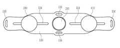
도 1은 본 발명의 일 실시예에 따른 자체 추진력 제공이 가능한 스케이트 보드를 나타낸 사시도,
도 2 및 도 3은 각각 도 1에 도시된 스케이트 보드의 부분 절개 분리 사시도,
도 4는 본 발명에 따른 스케이트 보드의 평면도,
도 5는 본 발명에 따른 스케이트 보드에 있어서 대(大) 코일스프링이 압축된 상태를 나타낸 정면도,
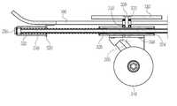
도 6은 본 발명에 따른 스케이트 보드에 있어서의 제 1발판부 설치 부위를 나타낸 부분 확대 단면도,
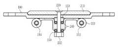
도 7은 본 발명에 따른 스케이트 보드에 있어서의 중앙회전부 설치 부위를 나타낸 확대 단면도,
도 8은 본 발명에 따른 스케이트 보드에 있어서의 제 2발판부 설치 부위를 나타낸 부분 확대 단면도,
도 9는 본 발명에 따른 스케이트 보드에 있어서의 제 1 및 제 2발판부 설치 부위를 나타낸 측단면도,
도 10은 본 발명에 따른 스케이트 보드에 있어서의 중앙회전부 설치 부위를 나타낸 측단면도,
도 11은 본 발명에 따른 스케이트 보드에 있어서 대(大) 코일스프링이 복원된 상태를 나타낸 정면도,
도 12는 본 발명에 따른 스케이트 보드에 있어서 발판이 좌우로 이동되는 상태를 나타낸 평면도.1 is a perspective view of a skateboard capable of providing self-propelling force according to an embodiment of the present invention;
FIG. 2 and FIG. 3 are partial cutaway exploded perspective views of the skateboard shown in FIG. 1,
4 is a plan view of a skateboard according to the present invention,
5 is a front view showing a state in which a large coil spring is compressed in the skateboard according to the present invention,
FIG. 6 is a partially enlarged cross-sectional view showing a first foot part mounting portion of a skateboard according to the present invention,
7 is an enlarged cross-sectional view of a skateboard according to the present invention,
FIG. 8 is a partially enlarged cross-sectional view showing a second foot part mounting portion of a skateboard according to the present invention,
FIG. 9 is a side cross-sectional view showing the first and second footrest portions of the skateboard according to the present invention,
FIG. 10 is a side sectional view showing a mounting portion of the main circuit in the skateboard according to the present invention,
11 is a front view showing a state in which a large coil spring is restored in the skateboard according to the present invention,
12 is a plan view showing a state where a footrest is moved to the left and right in a skateboard according to the present invention.
이하, 본 발명의 바람직한 실시예에 따른 자체 추진력 제공이 가능한 스케이트 보드를 상세히 설명하기로 한다.Hereinafter, a skateboard capable of providing self propulsion according to a preferred embodiment of the present invention will be described in detail.
이하에서 사용된 용어나 단어는 통상적이거나 사전적인 의미로 한정해서 해석되어서는 아니되며, 발명자는 그 자신의 발명을 최전의 방법으로 설명하기 위해 용어의 개념을 적절하게 정의할 수 있다는 원칙에 입각하여 본 발명의 기술적 사상에 부합하는 의미와 개념으로 해석되어야 할 것이다.It is to be understood that the terminology or words used herein are not to be construed in an ordinary sense or in any dictionary, and that the inventor may properly define the concept of a term to describe its invention in the best possible way And should be construed in accordance with the meaning and concept consistent with the technical idea of the present invention.
도 1은 본 발명의 일 실시예에 따른 자체 추진력 제공이 가능한 스케이트 보드를 나타낸 사시도이고, 도 2 및 도 3은 각각 도 1에 도시된 스케이트 보드의 부분 절개 분리 사시도이며, 도 4는 본 발명에 따른 스케이트 보드의 평면도이다.FIG. 1 is a perspective view showing a skateboard capable of providing self propulsion force according to an embodiment of the present invention, FIGS. 2 and 3 are partial cutaway perspective views of the skateboard shown in FIG. 1, And FIG.
또한, 도 5는 본 발명에 따른 스케이트 보드에 있어서 대(大) 코일스프링이 압축된 상태를 나타낸 정면도이고, 도 6은 본 발명에 따른 스케이트 보드에 있어서의 제 1발판부 설치 부위를 나타낸 부분 확대 단면도이며, 도 7은 본 발명에 따른 스케이트 보드에 있어서의 중앙회전부 설치 부위를 나타낸 확대 단면도이다.FIG. 5 is a front view showing a state where a large coil spring is compressed in the skateboard according to the present invention, and FIG. 6 is a partial enlarged view of a skateboard according to the present invention, And FIG. 7 is an enlarged cross-sectional view showing a mounting portion of the main assembly of the skateboard according to the present invention.
또한, 도 8은 본 발명에 따른 스케이트 보드에 있어서의 제 2발판부 설치 부위를 나타낸 부분 확대 단면도이고, 도 9는 본 발명에 따른 스케이트 보드에 있어서의 제 1 및 제 2발판부 설치 부위를 나타낸 측단면도이며, 도 10은 본 발명에 따른 스케이트 보드에 있어서의 중앙회전부 설치 부위를 나타낸 측단면도이다.8 is a partially enlarged cross-sectional view of a skateboard according to an embodiment of the present invention. FIG. 9 is a side view of the skateboard according to the present invention. And FIG. 10 is a side cross-sectional view showing a mounting portion of the main circuit in the skateboard according to the present invention.
또한, 도 11은 본 발명에 따른 스케이트 보드에 있어서 대(大) 코일스프링이 복원된 상태를 나타낸 정면도이고, 도 12는 본 발명에 따른 스케이트 보드에 있어서 발판이 좌우로 이동되는 상태를 나타낸 평면도이다.11 is a front view showing a state where a large coil spring is restored in the skateboard according to the present invention, and FIG. 12 is a plan view showing a state in which a footrest is moved to the left and right in a skateboard according to the present invention .
도 1 내지 도 12를 참조하면, 본 발명의 일 실시예에 따른 자체 추진력 제공이 가능한 스케이트 보드는 크게 보드본체(100), 중앙회전부(200), 제 1발판부(300), 제 2발판부(400), 그리고 탄성가이드부(500)를 포함하여 이루어진다.Referring to FIGS. 1 to 12, a skateboard capable of providing a self-propelling force according to an embodiment of the present invention includes a
도 1를 참조하면, 보드본체(100)는 가늘고 긴 널빤지 형태로서 사용자가 후술하는 복수의 발판(310)(410)을 통해 양 발을 각각 딛고 올라서는 것으로서, 좌우 양단부는 외부 미관을 고려하여 상향 경사지게 절곡된 형태를 가지고, 중앙부에는 후술하는 회전판(210)이 안착되기 위한 원형 형태의 안착홈(112)이 일정 깊이로서 형성되며, 이 안착홈(112)을 사이에 두고 발판(310)(410)이 설치되기 위한 타원 형태를 갖는 가이드공(114)이 각각 형성되고, 보드본체(100)의 각 가장자리에 사용자가 손을 넣어서 잡고 이동시키기 위한 손잡이공(116)이 각각 형성되어 있다.Referring to FIG. 1, the board
즉, 평면에서 보아 안착홈(112)의 상,하측과, 가이드공(114)의 좌,우측에 각각 손잡이공(116)이 형성되어 있다. 이때, 손잡이공(116)의 형성 부위는 반드시 4부위로 한정되지 않고, 1~4개 형성하는 것도 가능하다.That is, the
도 1 내지 도 3을 참조하면,중앙회전부(200)는 스케이트 보드 사용자가 한쪽 발을 딛고 방향을 전환하기 위한 것으로서, 회전판(210), 지지부재(220), 볼트부재(230), 너트부재(232), 복수의 스러스트 베어링(threst bearing)(240)를 포함한다.Referring to Figures 1 to 3, The
즉, 전술한 안착홈(112)에 직경 150㎜의 회전판(210)이 안착되고, 볼트부재(230)가 회전판(210)과 지지부재(220)를 관통하여 너트부재(232)에 결합됨에 따라 회전판(210)이 360도 회동자재한 구조를 가진다.That is, as the rotating
지지부재(220)는 중앙부 상,하면에 볼트부재(230)가 관통하는 스러스트 베어링(240)이 각각 안착되고, 좌우 양 단부에는 후술하는 봉조립체(510)가 관통하기 위한 중공의 날개(222)가 일체로서 형성되며, 지지부재(220)의 상면은 보드본체(100)에 다수의 스크류(미도시)를 통해 고정된다.The
한편, 중앙회전부(200)는 스러스트 베어링(240)를 포함하지 않는 경우 회전기능을 구현하지 않는 것도 가능하다. 즉, 필요에 따라 회전기능이 없이 고정기능만을 구현하는 것이 가능하다.On the other hand, when the throttle bearing 240 is not included in the
도 1, 도 2, 도 6을 참조하면, 제 1발판부(300)는 보드본체(100)의 중앙부를 중심으로 일측에 구비되어 발판(310)의 좌우 왕복운동을 통해 보드본체(100)를 이동시킴과 더불어 발판(310)의 자체 회전이 가능한 것으로서, 발판(310), 지지부재(320), 볼트부재(330), 휠(wheel) 조립체(340), 복수의 스러스트 베어링(350), 너트부재(360), 그리고 와셔(370)를 포함한다.1, 2, and 6, the
즉, 일측 가이드공(114)상에 원형 형태를 갖는 직경 200㎜의 발판(310)이 안착되고, 볼트부재(330)가 발판(310)과 지지부재(320)를 관통하여 너트부재(360)와 결합된다.That is, the
이때, 지지부재(320)는 중앙부 상,하면에 볼트부재(330)가 관통하는 스러스트 베어링(350)이 각각 안착되고, 좌우 양단부에는 후술하는 봉조립체(510)가 관통하기 위한 중공의 날개(322)가 일체로서 형성된다. 이에 따라 발판(310)은 지지부재(320)의 상면에서 회전 자재한 구조를 가진다.At this time, the
휠조립체(340)는 'U'자 형태의 단면을 갖는 상단의 수평연장부(342)가 지지부재(320)의 밑면에 다수의 스크류(도 6의 348)를 통해 결합되고, 수평연장부(342)와 일체로 형성된 몸체(344)의 좌우 양단부에는 휠(346)이 베어링(미도시)결합되어 회동자재한 구조를 가진다. 이때 상기 베어링은 일방향으로 회전시킬 수 있는 니들 클러치 베어링으로 구성함이 바람직하다.The
한편, 제 1발판부(300)는 스러스트 베어링(350)를 포함하지 않는 경우 회전기능을 구현하지 않는 것도 가능하다. 즉, 필요에 따라 회전기능이 없이 고정기능만을 구현하는 것이 가능하다.Meanwhile, it is also possible that the
도 1, 도 3, 도 7을 참조하면, 제 2발판부(400)는 보드본체(100)의 중앙부를 중심으로 타측에 구비되어 발판(410)의 좌우 왕복운동을 통해 보드본체(100)를 이동시킴과 더불어 발판(410)의 자체 회전이 가능한 것으로서, 발판(410), 지지부재(420), 볼트부재(430), 휠(wheel)조립체(440), 복수의 스러스트 베어링(450), 너트부재(460), 그리고 와셔(470)를 포함한다.1, 3, and 7, the
즉, 타측 가이드공(114)상에 직경 200㎜의 발판(410)이 안착되고, 볼트부재(430)가 발판(410)과 지지부재(420)를 관통하여 너트부재(460)와 결합된다.A
이때, 지지부재(420)는 중앙부 상,하면에 볼트부재(430)가 관통하는 스러스트 베어링(450)이 각각 안착되고, 좌우 양단부에는 후술하는 봉조립체(510)가 관통하기 위한 중공의 날개(422)가 일체로서 형성된다. 이에 따라 발판(410)은 지지부재(420)의 상면에서 회전 자재한 구조를 가진다.At this time, the
휠조립체(440)는 상단의 수평연장부(442)가 지지부재(420)의 밑면에 다수의 스크류(도 8의 448)를 통해 결합되고, 수평연장부(442)와 일체로 형성된 몸체(444)의 좌우 양단부에는 휠(446)이 베어링(미도시)결합되어 회동자재한 구조를 가진다. 이때 상기 베어링 또한 일방향으로 회전시킬 수 있는 니들 클러치 베어링으로 구성함이 바람직하다.The
한편, 제 2발판부(400)는 스러스트 베어링(450)를 포함하지 않는 경우 회전기능을 구현하지 않는 것도 가능하다. 즉, 필요에 따라 회전기능이 없이 고정기능만을 구현하는 것이 가능하다.On the other hand, if the
도 2 및 도 3을 참조하면, 탄성가이드부(500)는 보드본체(100)와 휠조립체(340)(440) 사이에 구비되어 지지부재(220)(320)(420)의 좌우 왕복운동을 가이드하는 것으로서, 봉조립체(510), 대소(大小) 코일스프링(520)(522), 마감부재(530), 스프링수납부재(540), 볼트부재(550), 그리고 너트부재(560)를 포함한다.2 and 3, the
봉조립체(510)는 좌우 1쌍으로 구비되는 바, 봉 형태를 갖는 알루미늄(Al) 재질의 심재(心材)(512)가 보다 큰 직경을 갖는 중공의 스테인레스(sus) 재질의 가이더(514)에 삽입되고, 이 가이더(514)는 전술한 지지부재(220)(320)(420)의 날개(222)(322)(422)를 관통하며, 심재(512)는 가이더(514) 내부에서 가이더의 내구성을 높이는 역할을 한다.The
또한, 가이더(514)의 양측 단부에는 후술하는 볼트부재(550)가 나사결합되기 위한 나사공(미도시)이 각각 형성되어 있다.Further, screw holes (not shown) for screwing a
이때, 심재(512)와 가이더(514)의 재질을 각각 알루미늄과 스테인레스로 한 것은 중량 감소를 위해서이며, 봉조립체(510)를 심재(512)와 가이더(514)의 조합체 대신 스테인레스 재질의 단일 구조체로 구성하는 것도 가능하다.The
또한, 지지부재(320)(420)의 좌우 양단부에는 가이더(514)의 좌우 왕복운동을 원활히 하기 위해 'T'자 단면 형태를 갖는 합성수지제 부싱(324, 424 참조)을 각각 삽입시키는 것도 가능하며, 다른 지지부재(220)에도 부싱(도 7의 224)을 사용할 수 있다.It is also possible to insert
한편, 대(大) 코일스프링(520)이 가이더(514)의 양측 외주면을 감싸도록 각각 구비되는 바, 이 대(大) 코일스프링(520)의 일단부는 후술하는 마감부재(530)에 접촉하고, 대(大) 코일스프링(520)의 타단부는 지지부재(320)(420)의 외측 단부와 접촉한다.A
또한, 지지부재(220)의 좌우 양단부에는 소(小) 코일스프링(522)이 가이더(514)의 양측 외주면을 감싸도록 각각 구비되며, 이 소(小) 코일스프링(522)은 지지부재(320)(420)가 좌우 왕복 운동하는 과정에서 지지부재(220)에 직접 접촉하는 것을 방지하고, 탄성 작용을 통해 지지부재(320)(420)가 좌우로 보다 부드럽게 이동하는 것을 돕게 된다.A
마감부재(530)는 'ㄱ'자형 단면을 구비하며, 좌우 양단부에 관통공(532)이 구비되어 있어서, 가이더(514)의 일부가 이 관통공(532)을 관통하여 후술하는 스프링수납부재(540)에 대(大) 코일스프링(520)과 함께 수납되고, 마감부재(530)의 상면은 보드본체(100)에 다수의 스크류(미도시)를 통해 고정된다.The
스프링수납부재(540)는 중공의 원통 형태로서, 선단부가 마감부재(530)에 용접에 의해 고정되고, 가이더(514)가 마감부재(530)를 관통하여 스프링수납부재(540) 내부에서 볼트부재(550)에 체결된다. 즉, 가이더(514)는 마감부재(530) 및 스프링수납부재(540)를 차례로 관통하여 볼트부재(550)에 체결된다.The
한편, 도면에는 도시가 되지 않았으나, 본 발명에 따른 스케이트 보드에 브레이크(brake) 기능을 부여할 수 있다. 즉, 양 스프링수납부재(540) 사이에서 높이 약 80㎜를 갖는 우레탄 소재 마찰부재(미도시)를 보드본체(100)의 밑면에 볼트부재를 통해 체결할 경우, 필요에 따라 사용자가 보드본체(100)의 전방 또는 후방을 발로 가압함에 따라 상기 마찰부재가 지면과 닿아서 스케이트 보드의 속도를 감소시키는 것이 가능하며, 도 2, 도 3 중 미설명 부호 250, 370, 470은 와셔이다.
Although not shown in the drawing, a skateboard according to the present invention may be provided with a brake function. That is, when a urethane-made friction member (not shown) having a height of about 80 mm between the both
이하에서는 상기한 구성을 갖는 본 발명의 작용을 설명한다.Hereinafter, the operation of the present invention having the above-described configuration will be described.
도 12를 참조하면, 본 발명에 따른 스케이트 보드의 발판(310)(410)과, 지지부재(320)(420), 그리고 휠조립체(340)(440)는 대(大) 코일스프링(520)의 복원력에 의해 가이드공(114)을 통해 회전판(210) 부근으로 이동하여 각각 회전판(210)의 일부를 가리고 있는 상태이다.12, the
이러한 상태에서 우선 사용자는 보드본체(100)의 손잡이공(116)을 잡고 원하는 장소로 이동하여 스케이트 보드를 지면에 놓고, 양 발을 발판(310)(410)에 올려 놓는다. 이후, 양 발을 벌리고 오므리는 동작을 차례로 반복함에 따라 지지부재(320)(420)가 가이더(514)의 외주면을 타고 중앙회전부(200)의 지지부재(220)를 중심으로 그 간격이 벌어지거나 좁아지며, 이와 동시에 대(大) 코일스프링(520)이 압축 또는 복원되면서 휠(346)(446)이 회전함에 따라 스케이트 보드가 일방향(전방향)으로 움직인다.In this state, the user first grasps the
즉, 양 발을 발판(310)(410)에 올려 놓은 상태에서 양 발을 벌리고 오므리는 동작을 차례로 반복함에 따라 스케이트 보드에 자체 추진력이 발생하면서 스케이트 보드가 움직이는 것이 가능하다.That is, as the two feet are placed on the
이때, 휠조립체(340)(440)에 적용된 베어링이 일방향 회전이 가능한 니들 클러치 베어링이므로 사용자가 양 발을 발판(310)(410)에 올려 놓은 상태에서 양 발을 벌리고 오므리는 동작을 차례로 반복함에 따라 발판(310)(410)의 간격이 좁아지거나 멀어지면서 양 발을 벌리고 오므리는 동작을 빨리 할수록 추진력이 배가되면서 휠(346)(446)이 일방향(전방향)으로 회전하는 속도를 높여서 스케이트 보드의 이동 속도를 높일 수 있게 된다(약 15~20km).In this case, since the bearings applied to the
또한, 사용자가 양 발을 발판(310)(410)에 올려 놓은 상태에서 양 발을 벌리고 오므리는 동작을 반복하는 과정에서 상대적으로 양 발의 간격이 넓은 경우 보다 큰 회전각으로 보드본체(100)를 회전시키는 것이 가능하고, 상대적으로 양 발의 간격이 좁은 경우 보다 작은 회전각으로 보드본체(100)를 회전시키는 것이 가능하다. 이에 따라 스케이트 보드의 사용 과정에서 급커브 회전 또는 완만한 회전을 도모할 수 있다.In addition, when the user places both feet on the
한편, 위와 같이 스케이트 보드의 사용 중 사용자가 진행 방향을 전환하고자 할 경우 오른발잡이를 예로 들어 설명하면 한쪽 발 즉, 제 1발판부(300)의 발판(310)에 있던 왼발을 회동자재한 상기 회전판(210)에 놓고 몸을 180도 회전시켜서 제 2발판부(400)의 발판(410)에 있던 오른발을 들어 제 1발판부(300)의 발판(310)에 놓은 후, 전술한 바와 같이 양 발을 벌리고 오므리는 동작을 반복함에 따라 대(大) 코일스프링(520)이 압축 또는 복원되면서 이와 동시에 휠(346)(446)이 회전하면서 스케이트 보드가 타방향(후방향)으로 움직이므로 스케이트 보드의 진행 방향을 반대 방향으로 전환할 수 있다.If the user wishes to switch the direction of the skateboard while the skateboard is in use, the left foot of the
상기와 같은 과정에서 본 발명에 따르면, 양 발을 모두 보드본체(100) 상부의 발판(310)(410)에 올려 놓은 상태에서 양 발을 벌리고 오므리는 동작을 반복함에 따라 스케이트 보드의 이동이 이루어진다. 이에 따라 종래 스케이트 보드의 추진력을 얻기 위해서 사용자가 한발을 보드에 올려놓고 다른 한발을 이용하여 지면에 접촉시켰다 떼는 동작을 반복적으로 수행하는 불편이 해소된다.According to the present invention, the skateboard is moved as the both feet are opened and closed in a state where both feet are placed on the
또한, 사용자가 어느 하나의 발을 계속하여 지면을 지치지 않아도 되므로 안전사고의 위험이 감소하고, 스케이트 보드의 사용 과정에서 쉽게 피로하게 않게 된다.In addition, since the user does not have to continue tilting the ground on one foot, the risk of a safety accident is reduced and the skateboard is not easily tired during the use process.
또한, 양 발을 모두 스케이트 보드 상부의 발판(310)(410)에 올려 놓은 상태에서 양 발을 벌리고 오므리는 동작을 통해 스케이트 보드의 이동이 이루어짐에 따라 스케이트 보드의 사용에 따른 중심을 잡기가 용이하므로 연령대에 관계없이 쉽게 스케이트 보드를 탈 수 있다.In addition, since both skates are moved by opening and closing both feet in a state where both feet are placed on the
또한, 발판(310)(410)에 올려 놓은 양 발을 벌리고 오므리는 동작을 빠르게 반복함에 따라 휠(346)(446)이 회전하는 속도를 높여서 스케이트 보드의 이동 속도를 높일 수 있게 된다.In addition, as the two legs placed on the
또한, 양 발을 벌리고 오므리는 동작을 반복적인 수행을 통해 남녀 성인 건강의 상징인 허벅지 근육 강화를 도모할 수 있다.It is also possible to strengthen the thigh muscles, which is a symbol of healthy sex for both men and women, by performing repetitive movements with both feet open and closed.
또한, 회전판(210)과 발판(310)(410)이 회전자재한 구조를 가짐에 따라 필요에 의해 사용자가 수시로 자세를 바꾸어서(180도) 스케이트 보드의 사용 과정에서 다양한 자세 변경이 가능하다.Further, since the
또한, 스케이트 보드의 사용 중 필요에 따라 제 1발판부(300)의 발판(310)에 있던 왼발을 회전판(210)에 놓고 몸을 180도 회전시켜서 제 2발판부(400)의 발판(410)에 있던 오른발을 들어 제 1발판부(300)의 발판(310)에 놓음에 따라 스케이트 보드를 사용하면서 스케이트 보드의 진행 방향을 반대 방향으로 전환할 수 있다.
The left foot of the
이와 같이 본 발명에 따른 자체 추진력 제공이 가능한 스케이트 보드를 예시된 도면을 참조로 설명하였으나, 본 명세서에 개시된 실시예와 도면에 의해 본 발명은 한정되지 않으며 그 발명의 기술사상 범위 내에서 당업자에 의해 다양한 변형이 이루어질 수 있음은 물론이다.
Although the present invention has been described with reference to exemplary embodiments thereof, it is to be understood that the invention is not limited to the disclosed exemplary embodiments, It goes without saying that various modifications can be made.
100 : 보드본체 112 : 안착홈
114 : 가이드공 116 : 손잡이공
200 : 중앙회전부 210 : 회전판
220,320,420 : 지지부재 222,322,422 : 날개
300 : 제 1발판부 310,410 : 발판
340,440 : 휠조립체 346,446 : 휠
400 : 제 2발판부 500 : 탄성가이드부
510 : 봉조립체 520 : 대(大) 코일스프링
522 : 소(小) 코일스프링 530 : 마감부재
532 : 관통공 540 : 스프링수납부재100: board body 112: seat groove
114: guide ball 116: handle ball
200: all of the central circuit 210:
220, 320, 420:
300:
340,440: Wheel assembly 346,446: Wheel
400: second foot part 500: elastic guide part
510: rod assembly 520: large coil spring
522: Small coil spring 530: Closing member
532: through hole 540: spring receiving member
Claims (5)
Translated fromKorean상기 보드본체(100)의 안착홈(112)에 안착되는 회전판(210)과, 중앙부 상,하면에 스러스트 베어링(240)이 각각 안착되고, 좌우 양 단부에는 중공의 날개(222)가 일체로 구비된 지지부재(220)와, 상기 회전판(210)과 지지부재(220)를 관통하여 너트부재(232)에 결합되는 볼트부재(230)를 포함하여 구성되고, 스케이트 보드 사용자가 한쪽 발을 딛고 방향을 전환하는 중앙회전부(200);
상기 보드본체(100)의 일측 가이드공(114)에 안착되는 발판(310)과, 중앙부 상,하면에 스러스트 베어링(350)이 각각 안착되고, 좌우 양단부에는 중공의 날개(322)가 일체로서 구비된 지지부재(320)와, 상기 발판(310)과 상기 지지부재(320)를 관통하여 너트부재(360)와 결합되는 볼트부재(330)와, 상단의 수평연장부(342)가 상기 지지부재(320)의 밑면에 결합되고, 상기 수평연장부(342)와 일체로 형성된 몸체(344)의 좌우 양단부에 휠(346)이 회동자재하게 구비된 휠(wheel) 조립체(340)를 포함하고, 상기 보드본체(100)의 중앙부를 중심으로 일측에 구비되어 상기 발판(310)의 좌우 왕복운동을 통해 상기 보드본체(100)를 이동시키는 제 1발판부(300);
상기 보드본체(100)의 타측 가이드공(114)에 안착되는 발판(410)과, 중앙부 상,하면에 스러스트 베어링(450)이 각각 안착되고, 좌우 양단부에는 중공의 날개(422)가 일체로서 구비된 지지부재(420)와, 상기 발판(410)과 상기 지지부재(420)를 관통하여 너트부재(460)와 결합되는 볼트부재(430)와, 상단의 수평연장부(442)가 상기 지지부재(420)의 밑면에 결합되고, 상기 수평연장부(442)와 일체로 형성된 몸체(444)의 좌우 양단부에 휠(446)이 회동자재하게 구비된 휠조립체(440)를 포함하고, 상기 보드본체(100)의 중앙부를 중심으로 타측에 구비되어 상기 발판(410)의 좌우 왕복운동을 통해 상기 보드본체(100)를 이동시키는 제 2발판부(400);
상기 보드본체(100)와 상기 휠조립체(340)(440) 사이에 구비되어 상기 지지부재(220)(320)(420)의 좌우 왕복운동을 가이드하는 탄성가이드부(500)를 포함하여 구성되는 자체 추진력 제공이 가능한 스케이트 보드.
A board main body 100 having a seating groove 112 formed at a central portion thereof with a predetermined depth, a guide hole 114 formed through the seating groove 112, respectively, and a user standing on both feet;
A thrust bearing 240 is mounted on a central portion of the rotating plate 210 and a hollow wing 222 is integrally formed on both left and right ends of the rotating plate 210, And a bolt member 230 which is coupled to the nut member 232 through the rotating plate 210 and the support member 220. The skateboard user holds the one foot A central circuit unit 200 for switching between the power supply and the power supply;
A thruster bearing 350 is mounted on a central portion of the foot plate 310 and a hollow wing 322 is integrally formed on both left and right ends of the foot plate 310, A bolt member 330 which is coupled to the nut member 360 through the foot plate 310 and the support member 320 and a horizontal extension portion 342 at the upper end of the support member 320, And a wheel assembly 340 coupled to a bottom surface of the horizontal extension portion 342 and having a wheel 346 pivotally mounted on both left and right ends of a body 344 formed integrally with the horizontal extension portion 342, A first pedestal part 300 provided at one side of the central part of the board body 100 to move the board body 100 through a reciprocating movement of the footrest 310;
And a thrust bearing 450 is mounted on the upper and lower surfaces of the pedestal 410 and a hollow wing 422 is integrally formed at the left and right ends of the pedestal 410, A bolt member 430 which is coupled to the nut member 460 through the foot plate 410 and the support member 420 and a horizontal extension portion 442 at the upper end of the support member 420, And a wheel assembly 440 coupled to a bottom surface of the horizontal extending portion 442 and having a wheel 446 pivotally mounted on both left and right ends of a body 444 integrally formed with the horizontal extending portion 442, A second pedestal part 400 provided on the other side of the central part of the pedestal 100 for moving the board body 100 through a left and right reciprocating motion of the pedestal 410;
And an elastic guide unit 500 provided between the board main body 100 and the wheel assemblies 340 and 440 to guide the reciprocating movement of the support members 220, Self-propelled skateboard.
상기 보드본체(100)의 좌우 양단부는 상향 경사지게 절곡된 형태를 구비한 것을 특징으로 하는 자체 추진력 제공이 가능한 스케이트 보드.
The method according to claim 1,
Wherein the left and right ends of the board body (100) are bent upwardly.
상기 보드본체(100)의 가장자리에는 사용자가 손을 넣어서 잡고 이동시키기 위한 손잡이공(116)이 적어도 하나 이상 구비된 것을 특징으로 하는 자체 추진력 제공이 가능한 스케이트 보드.
3. The method of claim 2,
Wherein at least one handle hole (116) is provided at an edge of the board main body (100) for a user to hold and move the handle.
상기 지지부재(220)(320)(420)의 좌우 양단부에는 가이더(514)의 좌우 왕복운동을 원활히 하기 위한 합성수지제 부싱(224)(324)(424)이 각각 삽입된 것을 특징으로 하는 자체 추진력 제공이 가능한 스케이트 보드.
The method according to claim 1,
And synthetic resin bushings 224, 324 and 424 are inserted into the left and right ends of the support members 220, 320 and 420 to smoothly reciprocate right and left of the guider 514. Skateboard available.
상기 탄성가이드부(500)는,
봉 형태를 갖는 알루미늄(Al) 재질의 심재(心材)(512)와;
상기 심재가 삽입되는 스테인레스(sus) 재질의 가이더(514)와;
상기 가이더(514)의 양측 외주면을 감싸도록 각각 구비되는 대소(大小) 코일스프링(520)(522)과;
상기 가이더(514)가 차례로 관통하는 마감부재(530) 및 스프링수납부재(540)와;
상기 가이더(514)에 체결되는 볼트부재(550)를 포함하는 것을 특징으로 하는 자체 추진력 제공이 가능한 스케이트 보드.The method according to claim 1,
The elastic guide part (500)
A core material 512 made of aluminum (Al) having a rod shape;
A guider 514 made of stainless steel into which the core is inserted;
Large and small coil springs 520 and 522 provided to surround both outer circumferential surfaces of the guider 514;
A closing member 530 and a spring receiving member 540 through which the guider 514 sequentially passes;
And a bolt member (550) fastened to the guider (514).
Priority Applications (5)
| Application Number | Priority Date | Filing Date | Title |
|---|---|---|---|
| KR1020150151519AKR101591253B1 (en) | 2015-10-30 | 2015-10-30 | Skate board providing driving power |
| US15/053,104US9868048B2 (en) | 2015-10-30 | 2016-02-25 | Skateboard capable of providing self-propulsive force |
| CN201680063371.1ACN108290069B (en) | 2015-10-30 | 2016-10-04 | The slide plate of motive force can be voluntarily provided |
| JP2018542066AJP6706782B2 (en) | 2015-10-30 | 2016-10-04 | A skateboard that can provide its own propulsion |
| PCT/KR2016/011089WO2017073917A1 (en) | 2015-10-30 | 2016-10-04 | Skateboard capable of providing self-propulsive force |
Applications Claiming Priority (1)
| Application Number | Priority Date | Filing Date | Title |
|---|---|---|---|
| KR1020150151519AKR101591253B1 (en) | 2015-10-30 | 2015-10-30 | Skate board providing driving power |
Publications (1)
| Publication Number | Publication Date |
|---|---|
| KR101591253B1true KR101591253B1 (en) | 2016-02-03 |
Family
ID=55355959
Family Applications (1)
| Application Number | Title | Priority Date | Filing Date |
|---|---|---|---|
| KR1020150151519AExpired - Fee RelatedKR101591253B1 (en) | 2015-10-30 | 2015-10-30 | Skate board providing driving power |
Country Status (5)
| Country | Link |
|---|---|
| US (1) | US9868048B2 (en) |
| JP (1) | JP6706782B2 (en) |
| KR (1) | KR101591253B1 (en) |
| CN (1) | CN108290069B (en) |
| WO (1) | WO2017073917A1 (en) |
Cited By (2)
| Publication number | Priority date | Publication date | Assignee | Title |
|---|---|---|---|---|
| CN107376312A (en)* | 2016-03-24 | 2017-11-24 | 丰田自动车株式会社 | Stand-riding mobile device |
| KR102007153B1 (en)* | 2019-03-26 | 2019-08-05 | 강인태 | Apparatus for Snake board |
Families Citing this family (5)
| Publication number | Priority date | Publication date | Assignee | Title |
|---|---|---|---|---|
| CN109475770B (en)* | 2016-05-10 | 2021-01-29 | 斯卡特创新有限公司 | Personal transportation device |
| WO2018152355A1 (en)* | 2017-02-15 | 2018-08-23 | Roll, Inc. | Roller board with one or more user-maneuverable trucks and north-seeking return mechanism |
| US9987546B1 (en)* | 2017-02-15 | 2018-06-05 | Roll, Inc. | Roller board with one or more user-maneuverable trucks and north-seeking return mechanism |
| US10858060B2 (en)* | 2017-02-15 | 2020-12-08 | Roll, Inc. | Roller board with one or more user-maneuverable trucks and north-seeking return mechanism |
| DE102019135306B3 (en)* | 2019-12-19 | 2021-03-18 | Dr. Ing. H.C. F. Porsche Ag | Electrically powered micro vehicle |
Citations (7)
| Publication number | Priority date | Publication date | Assignee | Title |
|---|---|---|---|---|
| KR200384634Y1 (en)* | 2005-02-25 | 2005-05-17 | 최종연 | Skate board |
| KR20050088978A (en)* | 2005-08-17 | 2005-09-07 | 최종연 | Skate board |
| KR100687458B1 (en)* | 2005-10-10 | 2007-03-08 | 이헌휘 | Stretchable Skateboards Climbing Tilt |
| KR20090005633A (en) | 2007-07-09 | 2009-01-14 | 조동표 | Skateboard |
| KR20090022791A (en) | 2007-08-31 | 2009-03-04 | 김진택 | Skateboard |
| KR101126427B1 (en)* | 2009-09-10 | 2012-03-28 | 정태인 | board |
| KR101479197B1 (en) | 2013-04-09 | 2015-01-08 | 한병찬 | skate board |
Family Cites Families (16)
| Publication number | Priority date | Publication date | Assignee | Title |
|---|---|---|---|---|
| US3771811A (en)* | 1972-08-16 | 1973-11-13 | Campos Bueno A De | Child {40 s coaster |
| US4181319A (en)* | 1978-04-26 | 1980-01-01 | Farrokh Hirbod | Ski skateboard |
| US4202559A (en)* | 1978-08-10 | 1980-05-13 | Piazza John Jr | Skateboard |
| US5236208A (en)* | 1991-09-03 | 1993-08-17 | Thomas Welsh | Platform steerable skateboard |
| US5224719A (en)* | 1992-05-15 | 1993-07-06 | Goodspeed Byron Lester | Skateboard |
| DE50112507D1 (en)* | 2000-03-08 | 2007-06-28 | Iq Carving Board Kg | Sliding board |
| US7628413B2 (en)* | 2004-06-21 | 2009-12-08 | Wayne Gallipoli | Wheeled terrain board and frame therefor |
| CN1323739C (en)* | 2004-10-18 | 2007-07-04 | 王可力 | Self-propelled traveling type scooter |
| JP2006122154A (en)* | 2004-10-26 | 2006-05-18 | Great Lotus Corp | Skateboard |
| US7980573B1 (en)* | 2005-04-06 | 2011-07-19 | Faris Naman | Spring board |
| KR200400315Y1 (en)* | 2005-05-20 | 2005-11-04 | 서대수 | Skate board |
| CN2853119Y (en)* | 2005-12-07 | 2007-01-03 | 安得淳 | Scooter |
| CN201055670Y (en)* | 2007-06-04 | 2008-05-07 | 徐志春 | Sliding plate capable of relative motion |
| WO2009037750A1 (en)* | 2007-09-19 | 2009-03-26 | Junzo Ota | Play apparatus and elastic mechanism |
| US20100044986A1 (en)* | 2008-08-22 | 2010-02-25 | Jeff Dannenberg | Riding platform with rotating deck |
| US20160001166A1 (en)* | 2013-03-19 | 2016-01-07 | Kazumine Kumada | Self-propelled skateboard |
- 2015
- 2015-10-30KRKR1020150151519Apatent/KR101591253B1/ennot_activeExpired - Fee Related
- 2016
- 2016-02-25USUS15/053,104patent/US9868048B2/ennot_activeExpired - Fee Related
- 2016-10-04WOPCT/KR2016/011089patent/WO2017073917A1/ennot_activeCeased
- 2016-10-04CNCN201680063371.1Apatent/CN108290069B/ennot_activeExpired - Fee Related
- 2016-10-04JPJP2018542066Apatent/JP6706782B2/ennot_activeExpired - Fee Related
Patent Citations (7)
| Publication number | Priority date | Publication date | Assignee | Title |
|---|---|---|---|---|
| KR200384634Y1 (en)* | 2005-02-25 | 2005-05-17 | 최종연 | Skate board |
| KR20050088978A (en)* | 2005-08-17 | 2005-09-07 | 최종연 | Skate board |
| KR100687458B1 (en)* | 2005-10-10 | 2007-03-08 | 이헌휘 | Stretchable Skateboards Climbing Tilt |
| KR20090005633A (en) | 2007-07-09 | 2009-01-14 | 조동표 | Skateboard |
| KR20090022791A (en) | 2007-08-31 | 2009-03-04 | 김진택 | Skateboard |
| KR101126427B1 (en)* | 2009-09-10 | 2012-03-28 | 정태인 | board |
| KR101479197B1 (en) | 2013-04-09 | 2015-01-08 | 한병찬 | skate board |
Cited By (4)
| Publication number | Priority date | Publication date | Assignee | Title |
|---|---|---|---|---|
| CN107376312A (en)* | 2016-03-24 | 2017-11-24 | 丰田自动车株式会社 | Stand-riding mobile device |
| CN107376312B (en)* | 2016-03-24 | 2019-04-30 | 丰田自动车株式会社 | Standing mobile device |
| KR102007153B1 (en)* | 2019-03-26 | 2019-08-05 | 강인태 | Apparatus for Snake board |
| WO2020197254A1 (en)* | 2019-03-26 | 2020-10-01 | 강인태 | Snakeboard device |
Also Published As
| Publication number | Publication date |
|---|---|
| JP6706782B2 (en) | 2020-06-10 |
| CN108290069B (en) | 2019-05-21 |
| CN108290069A (en) | 2018-07-17 |
| JP2018533454A (en) | 2018-11-15 |
| US9868048B2 (en) | 2018-01-16 |
| WO2017073917A1 (en) | 2017-05-04 |
| US20170120138A1 (en) | 2017-05-04 |
Similar Documents
| Publication | Publication Date | Title |
|---|---|---|
| KR101591253B1 (en) | Skate board providing driving power | |
| US4826159A (en) | Exercise kit, including balancing device and method of using same | |
| US5795277A (en) | Tilt walker sport board sport tilt walker board | |
| US3567242A (en) | Wheeled coaster device | |
| US7543834B2 (en) | Foot-propelled wheeled hobby or sport device | |
| KR20110119504A (en) | Sliding board | |
| KR100714176B1 (en) | Manual type running machine | |
| KR101243264B1 (en) | health training machine for amusements | |
| KR200372403Y1 (en) | Roller skate board | |
| KR100981801B1 (en) | Fish board | |
| KR100942442B1 (en) | Seesaw-driving type kick board | |
| KR20060028948A (en) | Roller skateboard | |
| JP2002210065A (en) | Vehicle | |
| CN112316401A (en) | A twist-push-driven sliding board with multiple playing methods | |
| KR20150124568A (en) | Tri-Circle Kick Scooters | |
| KR101344625B1 (en) | Self-propulsion skate board | |
| KR100847669B1 (en) | Brain development exercise mechanism | |
| KR101336367B1 (en) | Skateboard that is possible self driving | |
| KR100483061B1 (en) | Roller board | |
| JPH10108937A (en) | Exercising play device self-traveling while rotating at 360× by balance | |
| KR200418047Y1 (en) | Non-motorized treadmill | |
| KR20130055170A (en) | Land surfing board | |
| KR200301206Y1 (en) | Roller board | |
| KR20150145825A (en) | Trik | |
| WO2016153392A2 (en) | Roller skates |
Legal Events
| Date | Code | Title | Description |
|---|---|---|---|
| PA0109 | Patent application | St.27 status event code:A-0-1-A10-A12-nap-PA0109 | |
| PA0201 | Request for examination | St.27 status event code:A-1-2-D10-D11-exm-PA0201 | |
| R17-X000 | Change to representative recorded | St.27 status event code:A-3-3-R10-R17-oth-X000 | |
| P11-X000 | Amendment of application requested | St.27 status event code:A-2-2-P10-P11-nap-X000 | |
| P13-X000 | Application amended | St.27 status event code:A-2-2-P10-P13-nap-X000 | |
| A302 | Request for accelerated examination | ||
| PA0302 | Request for accelerated examination | St.27 status event code:A-1-2-D10-D17-exm-PA0302 St.27 status event code:A-1-2-D10-D16-exm-PA0302 | |
| D13-X000 | Search requested | St.27 status event code:A-1-2-D10-D13-srh-X000 | |
| D14-X000 | Search report completed | St.27 status event code:A-1-2-D10-D14-srh-X000 | |
| E701 | Decision to grant or registration of patent right | ||
| PE0701 | Decision of registration | St.27 status event code:A-1-2-D10-D22-exm-PE0701 | |
| GRNT | Written decision to grant | ||
| PR0701 | Registration of establishment | St.27 status event code:A-2-4-F10-F11-exm-PR0701 | |
| PR1002 | Payment of registration fee | St.27 status event code:A-2-2-U10-U11-oth-PR1002 Fee payment year number:1 | |
| PG1601 | Publication of registration | St.27 status event code:A-4-4-Q10-Q13-nap-PG1601 | |
| PN2301 | Change of applicant | St.27 status event code:A-5-5-R10-R11-asn-PN2301 | |
| PN2301 | Change of applicant | St.27 status event code:A-5-5-R10-R14-asn-PN2301 | |
| S20-X000 | Security interest recorded | St.27 status event code:A-4-4-S10-S20-lic-X000 | |
| R18-X000 | Changes to party contact information recorded | St.27 status event code:A-5-5-R10-R18-oth-X000 | |
| P22-X000 | Classification modified | St.27 status event code:A-4-4-P10-P22-nap-X000 | |
| FPAY | Annual fee payment | Payment date:20181117 Year of fee payment:4 | |
| PR1001 | Payment of annual fee | St.27 status event code:A-4-4-U10-U11-oth-PR1001 Fee payment year number:4 | |
| FPAY | Annual fee payment | Payment date:20200211 Year of fee payment:5 | |
| PR1001 | Payment of annual fee | St.27 status event code:A-4-4-U10-U11-oth-PR1001 Fee payment year number:5 | |
| PR1001 | Payment of annual fee | St.27 status event code:A-4-4-U10-U11-oth-PR1001 Fee payment year number:6 | |
| PC1903 | Unpaid annual fee | St.27 status event code:A-4-4-U10-U13-oth-PC1903 Not in force date:20220129 Payment event data comment text:Termination Category : DEFAULT_OF_REGISTRATION_FEE | |
| PC1903 | Unpaid annual fee | St.27 status event code:N-4-6-H10-H13-oth-PC1903 Ip right cessation event data comment text:Termination Category : DEFAULT_OF_REGISTRATION_FEE Not in force date:20220129 | |
| K11-X000 | Ip right revival requested | St.27 status event code:A-6-4-K10-K11-oth-X000 | |
| K12-X000 | Request for ip right revival rejected | St.27 status event code:A-6-4-K10-K12-oth-X000 |