KR101589006B1 - Safety protection system for pen needles - Google Patents
Safety protection system for pen needlesDownload PDFInfo
- Publication number
- KR101589006B1 KR101589006B1KR1020150145029AKR20150145029AKR101589006B1KR 101589006 B1KR101589006 B1KR 101589006B1KR 1020150145029 AKR1020150145029 AKR 1020150145029AKR 20150145029 AKR20150145029 AKR 20150145029AKR 101589006 B1KR101589006 B1KR 101589006B1
- Authority
- KR
- South Korea
- Prior art keywords
- cap
- small
- support
- needle
- supporting
- Prior art date
- Legal status (The legal status is an assumption and is not a legal conclusion. Google has not performed a legal analysis and makes no representation as to the accuracy of the status listed.)
- Active
Links
Images


Classifications
- A—HUMAN NECESSITIES
- A61—MEDICAL OR VETERINARY SCIENCE; HYGIENE
- A61M—DEVICES FOR INTRODUCING MEDIA INTO, OR ONTO, THE BODY; DEVICES FOR TRANSDUCING BODY MEDIA OR FOR TAKING MEDIA FROM THE BODY; DEVICES FOR PRODUCING OR ENDING SLEEP OR STUPOR
- A61M5/00—Devices for bringing media into the body in a subcutaneous, intra-vascular or intramuscular way; Accessories therefor, e.g. filling or cleaning devices, arm-rests
- A61M5/50—Devices for bringing media into the body in a subcutaneous, intra-vascular or intramuscular way; Accessories therefor, e.g. filling or cleaning devices, arm-rests having means for preventing re-use, or for indicating if defective, used, tampered with or unsterile
- A61M5/5066—Means for preventing re-use by disconnection of piston and piston-rod
- A—HUMAN NECESSITIES
- A61—MEDICAL OR VETERINARY SCIENCE; HYGIENE
- A61M—DEVICES FOR INTRODUCING MEDIA INTO, OR ONTO, THE BODY; DEVICES FOR TRANSDUCING BODY MEDIA OR FOR TAKING MEDIA FROM THE BODY; DEVICES FOR PRODUCING OR ENDING SLEEP OR STUPOR
- A61M5/00—Devices for bringing media into the body in a subcutaneous, intra-vascular or intramuscular way; Accessories therefor, e.g. filling or cleaning devices, arm-rests
- A61M5/178—Syringes
- A61M5/31—Details
- A61M5/32—Needles; Details of needles pertaining to their connection with syringe or hub; Accessories for bringing the needle into, or holding the needle on, the body; Devices for protection of needles
- A61M5/3293—Needles; Details of needles pertaining to their connection with syringe or hub; Accessories for bringing the needle into, or holding the needle on, the body; Devices for protection of needles characterised by features of the needle hub
- A—HUMAN NECESSITIES
- A61—MEDICAL OR VETERINARY SCIENCE; HYGIENE
- A61M—DEVICES FOR INTRODUCING MEDIA INTO, OR ONTO, THE BODY; DEVICES FOR TRANSDUCING BODY MEDIA OR FOR TAKING MEDIA FROM THE BODY; DEVICES FOR PRODUCING OR ENDING SLEEP OR STUPOR
- A61M5/00—Devices for bringing media into the body in a subcutaneous, intra-vascular or intramuscular way; Accessories therefor, e.g. filling or cleaning devices, arm-rests
- A61M5/178—Syringes
- A61M5/31—Details
- A61M5/32—Needles; Details of needles pertaining to their connection with syringe or hub; Accessories for bringing the needle into, or holding the needle on, the body; Devices for protection of needles
- A61M5/3202—Devices for protection of the needle before use, e.g. caps
- A—HUMAN NECESSITIES
- A61—MEDICAL OR VETERINARY SCIENCE; HYGIENE
- A61M—DEVICES FOR INTRODUCING MEDIA INTO, OR ONTO, THE BODY; DEVICES FOR TRANSDUCING BODY MEDIA OR FOR TAKING MEDIA FROM THE BODY; DEVICES FOR PRODUCING OR ENDING SLEEP OR STUPOR
- A61M5/00—Devices for bringing media into the body in a subcutaneous, intra-vascular or intramuscular way; Accessories therefor, e.g. filling or cleaning devices, arm-rests
- A61M5/178—Syringes
- A61M5/31—Details
- A61M5/32—Needles; Details of needles pertaining to their connection with syringe or hub; Accessories for bringing the needle into, or holding the needle on, the body; Devices for protection of needles
- A61M5/3205—Apparatus for removing or disposing of used needles or syringes, e.g. containers; Means for protection against accidental injuries from used needles
- A61M5/321—Means for protection against accidental injuries by used needles
- A61M5/3243—Means for protection against accidental injuries by used needles being axially-extensible, e.g. protective sleeves coaxially slidable on the syringe barrel
- A61M5/326—Fully automatic sleeve extension, i.e. in which triggering of the sleeve does not require a deliberate action by the user
- A—HUMAN NECESSITIES
- A61—MEDICAL OR VETERINARY SCIENCE; HYGIENE
- A61M—DEVICES FOR INTRODUCING MEDIA INTO, OR ONTO, THE BODY; DEVICES FOR TRANSDUCING BODY MEDIA OR FOR TAKING MEDIA FROM THE BODY; DEVICES FOR PRODUCING OR ENDING SLEEP OR STUPOR
- A61M5/00—Devices for bringing media into the body in a subcutaneous, intra-vascular or intramuscular way; Accessories therefor, e.g. filling or cleaning devices, arm-rests
- A61M5/50—Devices for bringing media into the body in a subcutaneous, intra-vascular or intramuscular way; Accessories therefor, e.g. filling or cleaning devices, arm-rests having means for preventing re-use, or for indicating if defective, used, tampered with or unsterile
- A—HUMAN NECESSITIES
- A61—MEDICAL OR VETERINARY SCIENCE; HYGIENE
- A61M—DEVICES FOR INTRODUCING MEDIA INTO, OR ONTO, THE BODY; DEVICES FOR TRANSDUCING BODY MEDIA OR FOR TAKING MEDIA FROM THE BODY; DEVICES FOR PRODUCING OR ENDING SLEEP OR STUPOR
- A61M5/00—Devices for bringing media into the body in a subcutaneous, intra-vascular or intramuscular way; Accessories therefor, e.g. filling or cleaning devices, arm-rests
- A61M5/178—Syringes
- A61M5/31—Details
- A61M5/32—Needles; Details of needles pertaining to their connection with syringe or hub; Accessories for bringing the needle into, or holding the needle on, the body; Devices for protection of needles
- A61M5/3205—Apparatus for removing or disposing of used needles or syringes, e.g. containers; Means for protection against accidental injuries from used needles
- A61M5/321—Means for protection against accidental injuries by used needles
- A61M5/3243—Means for protection against accidental injuries by used needles being axially-extensible, e.g. protective sleeves coaxially slidable on the syringe barrel
- A61M5/3245—Constructional features thereof, e.g. to improve manipulation or functioning
- A61M2005/3247—Means to impede repositioning of protection sleeve from needle covering to needle uncovering position
- A—HUMAN NECESSITIES
- A61—MEDICAL OR VETERINARY SCIENCE; HYGIENE
- A61M—DEVICES FOR INTRODUCING MEDIA INTO, OR ONTO, THE BODY; DEVICES FOR TRANSDUCING BODY MEDIA OR FOR TAKING MEDIA FROM THE BODY; DEVICES FOR PRODUCING OR ENDING SLEEP OR STUPOR
- A61M5/00—Devices for bringing media into the body in a subcutaneous, intra-vascular or intramuscular way; Accessories therefor, e.g. filling or cleaning devices, arm-rests
- A61M5/178—Syringes
- A61M5/31—Details
- A61M5/32—Needles; Details of needles pertaining to their connection with syringe or hub; Accessories for bringing the needle into, or holding the needle on, the body; Devices for protection of needles
- A61M5/3205—Apparatus for removing or disposing of used needles or syringes, e.g. containers; Means for protection against accidental injuries from used needles
- A61M5/321—Means for protection against accidental injuries by used needles
- A61M5/3243—Means for protection against accidental injuries by used needles being axially-extensible, e.g. protective sleeves coaxially slidable on the syringe barrel
- A61M5/326—Fully automatic sleeve extension, i.e. in which triggering of the sleeve does not require a deliberate action by the user
- A61M2005/3267—Biased sleeves where the needle is uncovered by insertion of the needle into a patient's body
- A—HUMAN NECESSITIES
- A61—MEDICAL OR VETERINARY SCIENCE; HYGIENE
- A61M—DEVICES FOR INTRODUCING MEDIA INTO, OR ONTO, THE BODY; DEVICES FOR TRANSDUCING BODY MEDIA OR FOR TAKING MEDIA FROM THE BODY; DEVICES FOR PRODUCING OR ENDING SLEEP OR STUPOR
- A61M5/00—Devices for bringing media into the body in a subcutaneous, intra-vascular or intramuscular way; Accessories therefor, e.g. filling or cleaning devices, arm-rests
- A61M5/50—Devices for bringing media into the body in a subcutaneous, intra-vascular or intramuscular way; Accessories therefor, e.g. filling or cleaning devices, arm-rests having means for preventing re-use, or for indicating if defective, used, tampered with or unsterile
- A61M5/5066—Means for preventing re-use by disconnection of piston and piston-rod
- A61M2005/5073—Means for preventing re-use by disconnection of piston and piston-rod by breaking or rupturing the connection parts
- A—HUMAN NECESSITIES
- A61—MEDICAL OR VETERINARY SCIENCE; HYGIENE
- A61M—DEVICES FOR INTRODUCING MEDIA INTO, OR ONTO, THE BODY; DEVICES FOR TRANSDUCING BODY MEDIA OR FOR TAKING MEDIA FROM THE BODY; DEVICES FOR PRODUCING OR ENDING SLEEP OR STUPOR
- A61M5/00—Devices for bringing media into the body in a subcutaneous, intra-vascular or intramuscular way; Accessories therefor, e.g. filling or cleaning devices, arm-rests
- A61M5/002—Packages specially adapted therefor, e.g. for syringes or needles, kits for diabetics
Landscapes
- Health & Medical Sciences (AREA)
- Engineering & Computer Science (AREA)
- Heart & Thoracic Surgery (AREA)
- Vascular Medicine (AREA)
- Anesthesiology (AREA)
- Biomedical Technology (AREA)
- Hematology (AREA)
- Life Sciences & Earth Sciences (AREA)
- Animal Behavior & Ethology (AREA)
- General Health & Medical Sciences (AREA)
- Public Health (AREA)
- Veterinary Medicine (AREA)
- Environmental & Geological Engineering (AREA)
- Infusion, Injection, And Reservoir Apparatuses (AREA)
Abstract
Translated fromKorean
Description
Translated fromKorean본 발명은 펜 타입 주사기에 체결하여 1회 사용 용도로 사용되는 펜니들(Pen-Needle)에 관한 것으로, 더욱 상세하게는 펜 타입 주사기에 나사결합방식으로 삽입 체결되는 1회성 소모품인 펜니들을 사용자가 1회 사용 후 재사용이 불가능하도록 하는 안전보호시스템을 갖춘 펜니들에 관한 것이다.
BACKGROUND OF THE INVENTION 1. Field of the Invention The present invention relates to a pen-needle which is fastened to a pen-type syringe to be used for a single use, and more particularly to a pen-needle which is a one- To prevent reuse after one use of the pen.
본 발명은 펜 타입 주사기에 결합하여 1회용 소모품으로 사용되는 니들(주사바늘)을 중심부에 구비한 허브(HUB) 즉, 펜니들(Pen-Needle)의 반복적인 재사용을 막고 니들 찔림으로 인한 고통과 감염을 예방하기 위하여 펜니들에 대한 안전보호시스템에 관한 것으로,The present invention relates to a device for preventing repetitive reuse of a hub (HUB) having a needle (injector needle) used as a disposable consumable article in a central portion by being coupled to a pen type injector, The present invention relates to a safety protection system for a pen needle to prevent infection,
상기 니들을 중심부에 구비한된 허브를 펜니들이라고 통칭되며 펜 타입 주사기는 수 회에서 수십 회 주사가 가능한 약제가 수용되어 있으며, 사용자의 누름 압력에 의하여 일정량의 약제가 인체로 주사될 수 있도록 구성되어 있고 감염 등의 위험으로 인하여 사용시마다 펜니들을 교체해 가며 1회용으로 사용할 수 있도록 되어 있다.The pen type syringe includes a medicament capable of scanning several times to several tens of times, and is configured such that a predetermined amount of medicament can be injected into the human body due to a pressing pressure of the user And it is possible to use it as disposable one by replacing the pen needle every time of use due to the risk of infection.
그런데 종래에는 1회용 소모품인 상기 펜니들을 사용자가 반복적으로 재사용하거나 부주의에 의한 피부접촉 또는 찔림으로 인한 2차 감염이 발생하는 문제점이 자주 발생하고 있고 이를 해결하기 위한 여러가지 기능의 안전 펜니들은 개발되어 왔으나 그 구조가 복잡하고 부품의 수가 많아 제품의 크기가 크며 그만큼 제조 단가도 증가하는 문제점이 있지만 탄성 있는 재질의 셔틀 콕(Shuttlecock) 모양의 지지대 날개를 활용하여 구조를 단순화하고 부품 수를 줄여 펜니들의 크기와 제조공정을 줄인 안전기능을 갖춘 펜니들은 아직까지 개발되지 않았다.
However, in the related art, there are frequent problems that the user repeatedly reuses the pen needle, which is a disposable consumable item, or secondary infections due to skin contact or piercing caused by carelessness. To solve this problem, various safety pen needles However, there is a problem that the structure is complicated and the number of parts is large, and the size of the product is large and the manufacturing cost is increased. However, by using a supportcock-shaped support wing of an elastic material, the structure is simplified, Pen needles with safety features that reduce needle size and manufacturing processes have not yet been developed.
JP 23512196 A (안전한 펜니들(needle) 어셈블리) 2009. 02. 05.JP 23512196 A (safety pen needle assembly) 2009. 02. 05.
JP 24500063 A (안전 펜니들(needle) 어셈블리) 2009. 08. 17.JP 24500063 A (safety pen needle assembly) Aug. 17, 2009
JP 13286562 A (의료용 안전 처리 캡 어셈블리) 2001.03. 21.JP 13286562 A (medical safety treatment cap assembly) 2001.03. 21.
US US20120277685 A1 (SAFETY PEN NEEDLE ASSEMBLY) 2011. 04. 28.US US20120277685 A1 (SAFETY PEN NEEDLE ASSEMBLY) 2011. 04. 28.
JP 27112489 A (능동 형의 안전 펜니들(needle) 어셈블리) 2014. 12. 10.
JP 27112489 A (active safety pen needle assembly) 2014. 12. 10.
본 발명은 배경기술에서 기술한 바와 같은 문제점을 해결하도록 안출된 것으로, 종래의 주사기 펜에 체결되어 1회용으로 사용되는 펜니들은 니들이 허브 외부로 돌출되어 사용자들에게 집적적으로 노출된 형태를 갖추고 있어 찔림 등의 우려와 1회용 소모품인 펜니들을 수회 재사용할 수 있어 2차 감염 등의 위험이 상존하고 있어 안전기능과 재사용을 방지하는 구조의 안전 펜니들은 보건안전문제와 결부되어 사용자의 안전을 위해서 반드시 필요하다.The present invention was conceived to solve the problems as described in the background art. The pen needle, which is fastened to the conventional syringe pen and used for one time, has a shape in which the needle protrudes to the outside of the hub and is integrally exposed to the users There is a risk of stabbing and disposable consumables. Pen needles can be reused several times, so there is a risk of secondary infections. Safety Pen needles are designed to prevent safety functions and reuse. .
상기와 같은 문제점을 극복하기 위해 1회 사용용도인 펜니들의 재 사용을 근본적으로 방지하고 안전기능을 갖춘 펜니들은 현재도 계속 연구 개발되고 있으나 새롭게 시도되는 안전기능과 1회사용 용도로 제한되는 안전기능을 갖춘 펜니들은, 재사용 방지와 안전기능을 구현하기 위해 기존의 펜니들 대비 구성되는 부품의 수가 증가되어 구조가 복잡하고 제조공정 역시 복잡해 질 수 밖에 없으며 펜니들의 외형의 크기 역시 기존 제품보다 비대할 뿐만 아니라 제작비용 또한 동반 상승하게 되므로 최종적으로 사용자들이 펜 타입 주사기에 체결하여 주사약제를 자가주사투여 시 1회용 소모품인 펜니들의 크기에 대한 심리적 부담감과 구매비용의 증가에 따른 경제적 부담이 증가되고 있다.In order to overcome the above problem, the pen needle which fundamentally prevents the reuse of the pen needle for the one-time use and has the safety function is still being researched and developed, but it is limited to the newly tried safety function and the one- The pen needle with safety function has to increase the number of parts constituted compared to the existing pen needle in order to realize the reuse prevention and the safety function, the structure is complicated and the manufacturing process is also complicated, and the size of the pen needle is also changed The cost of manufacturing the pen needle is increased and the cost of manufacturing the pen tip is increased. Therefore, when the user inserts the injection agent into the pen type syringe, the psychological burden on the size of the pen needle, Is increasing.
따라서, 본 발명은 1회성 소모품인 펜니들에 대하여 기존의 펜니들의 기능은 유지하면서 사용자로 하여금 재사용을 원천적으로 막아 2차 감염 등의 위험을 방지하는 안전기능을 구비한 1회용 펜니들을 구현함에 있어 종래의 안전기능을 갖춘 펜니들 대비 단순한 원리로 제조 및 사용이 간단하며 간단한 구조와 기능으로 잔 고장을 줄이고 부품의 수를 획기적으로 줄여 전체적인 크기를 줄임으로써 사용자의 주사약제 투여 시 펜니들 크기에서 오는 심리적 부담감을 줄이고 줄어드는 부품의 수 만큼 제조원가를 절감하여 사용자들의 경제적 부담을 줄일 수 있는 펜니들에 대한 안전보호시스템을 제시하는데 목적이 있다.Accordingly, the present invention implements a disposable pen needle having a safety function for preventing the risk of secondary infection by preventing the reuse of the pen needle while maintaining the function of the pen needle as a one-time consumable item It is easy to manufacture and use with simple principle compared to pen needle with conventional safety function. It can reduce the number of parts due to simple structure and function, and reduce the total size by reducing the number of parts. Therefore, pen needle size And to provide a safety protection system for a pen needle that can reduce the manufacturing cost by reducing the number of components that are reduced in cost, thereby reducing the economic burden on the user.
상기 목적을 달성하기 위한 본 발명은 펜 타입 주사기에 체결하여 사용되는 1회용 소모품인 펜니들을 사용자가 한번 사용된 이후 펜니들의 재사용을 불가능하게 만드는 안전보호시스템이 구비된 펜니들에 관한 것으로서,In order to accomplish the above object, the present invention provides a pen needle having a safety protection system that makes it impossible to reuse the pen needle after the user once uses the pen needle, which is a disposable consumable item used by being fastened to the pen type syringe,
펜 타입 주사기에 체결되는 펜니들에 있어서, 상기 펜 타입 주사기는 주사약제 수용 부 상단에 나사 부를 감싸는 형태를 가지며, 펜니들을 구성하는 허브 하단 부의 내측 면에 상기 펜 타입 주사기 주사약제 수용체 상단의 나선 부와 나결합결방식에 의한 체결이 가능하도록 나선 부를 구비하고 있고 니들이 관통하여 수용되는 원기둥형태의 돌기 하단 부에는 셔틀 콕(Shuttlecock) 모양의 소캡 지지대가 소캡의 누름 압력에 하강하여 스프링의 탄력성에 의해 소캡이 다시 상승할 시 소캡과 함께 상승하지 아니하도록 고정시키는 돌기가 형성되어 있고,The pen type syringe is configured to enclose a screw portion at the upper end of the injection medicine receiving portion. The pen type syringe has a spiral portion at the upper end of the pen type syringe injection medicine receiver on the inner surface of the lower end portion of the hub constituting the pen needle, A small-cap support in the shape of a shuttlecock is lowered to a pressing pressure of the small-cap, so that the elasticity of the spring is lowered to the lower end of the cylindrical projection having the spiral portion so that the screw can be fastened by the coupling method. A protrusion for fixing the small cap so as not to rise together with the small cap when the small cap is lifted again is formed,
지지대의 하단 부에는 상기 돌기를 수용하고 고정시키는 구가 형성되어 있으며 허브 상부에 결합되어 허브를 전체적으로 감싸면서 내부에 스프링을 수용하며 상부에는 소캡을 수용하는 원통모양의 중캡이 있고 상기 중캡 상부에 위치하는 소캡은 내부에 상기 셔틀 콕 모양의 지지대를 수용하고 있으며 하단 부에는 지지대가 지지력이 이탈되지 못하기 저지하는 원형 띠 모양의 돌기가 형성되어 있으며,The lower end of the support member is formed with a hole for receiving and fixing the protrusion. The support member is coupled to the upper portion of the hub so as to surround the hub and accommodate the spring therein. The hub has a cylindrical middle cap for accommodating the small cap. Shaped protrusions are formed at the lower end portion of the small cap to prevent the support force from being detached from the support cap,
상기 소캡과 중캡과 셔틀 콕 모양의 지지대는 모두 니들 지지용 막대모양의 원기둥이 관통될 수 있도록 상하 모두 개구되어 있어 사용자가 본 발명으로 주사약제를 자가주사투여 할 시 피부에 소캡을 접촉시키는 압력에 의해 소캡이 중캡 내부로 지지대와 함께 수용되며 주사투약 완료 후 펜니들을 피부와 이격시킬 시 중캡 내부의 소캡은 스프링의 탄력성에 의해 중캡 상부로 원 위치하게 되며 이때, 셔틀 콕 모양의 지지대는 니들을 수용용 막대모양의 돌기 하단부에 천공된 구에 지지대 하단의 돌기가 삽입 고정되어 있음으로 인하여 상승된 소캡과 분리되어 중캡 내부에서 소캡의 하면 부와 허브 상면 부 사이에 위치하게 되고,The small cap, the middle cap, and the shuttlecock-like support base are both opened vertically so that the rod-like cylinder for needle support can pass through. When the user injects the injection agent by self-injection, The small cap is accommodated with the support in the middle of the cap, and when the pen needle is separated from the skin after the injection is completed, the small cap inside the cap is positioned to the top of the middle cap by the elasticity of the spring, The protrusion of the lower part of the support is inserted and fixed in the hole formed at the lower end of the rod for receiving, so that it is separated from the raised small cap and positioned between the lower part of the small cap and the upper part of the hub,
소캡 하단에 개구된 원형의 크기는 전개된 지지대의 날개 지름보다 작고 지지대 몸통보다는 크게 형성되어 소캡이 1회 눌림 압력으로 소캡이 하강할 때에는 소캡 내부에서 셔틀 콕 모양의 지지대는 모양의 변형이 전혀 없으나 스프링의 탄력성으로 인해 소캡이 상승하여 원 위치 될 시에는 니들 수용용 막대모양의 원 기둥 하단의 돌기에 고정되어 있기에 지지대의 전개된 날개는 상기 소캡 하단의 원형 개구를 지날 시에는 오므려졌다가 지지대 상단을 완전히 벗어나게 되는 시점에서 오므라져 있는 지지대는 다시 펼쳐져 전개 되어 소캡 하단의 원형 개구의 지름 크기보다 넓어져 소캡을 떠 받치는 지지력이 발생되어 이후 소캡이 다시 중캡 내부에서 하강하지 못하게 되어 니들이 소캡 상단 외부로 들어나지 못하게 되므로 원천적으로 1회 사용되어진 펜니들의 재사용이 불가능하게 되는 것을 특징으로 한다.
The size of the circular opening at the lower end of the small cap is smaller than the wing diameter of the deployed support and larger than the support body so that when the small cap is lowered by the pressure of the small cap once, there is no deformation of the shape of the shuttlecock- When the small cap is raised due to the elasticity of the spring and is fixed to the protrusion at the lower end of the rod-shaped barrel for receiving the needle, the unfolded wing of the supporter is disengaged when it passes the circular opening at the lower end of the small cap, A supporting force for supporting the small cap is generated so that the small cap can not be lowered from the inside of the middle cap again so that the needles can be lowered to the outside of the upper side of the small cap, And therefore, it is used only once It characterized in that the re-use of the needle is impossible.
본 발명에 의하면, 다양한 치료목적으로 다용도로 사용되어 지는 펜 타입 주사기에 체결하여 1회용도로 사용되어 지는 펜니들(Pen-Needle)을 1회 사용한 이후 재사용을 원천적으로 막고 부주의에 따른 니들 찔림에 의한 2차 감염을 예방하기 위하여 펜니들에 대한 안전보호시스템을 적용한 것으로써,According to the present invention, it is possible to prevent re-use after one-time use of a pen-needle used for disposable use by connecting to a pen type syringe which is used versatility for various therapeutic purposes, In order to prevent secondary infection, the safety protection system for pen needle is applied,
펜니들을 구성하는 허브에 소캡과 중캡 및 셔틀 콕(Shuttlecock) 모양의 지지대 날개와 스프링을 어셈블리로 하는 매우 간단하고 단순한 구조로 구성되어 효용 대비 제조비용을 줄일 수 있어 그만큼 경제적이고 내장되는 스프링은 니들(Needle)과 분리된 공간인 중캡 내부에 위치하여 니들(Needle)이 스프링과 직접적 접촉될 염려가 전혀 없는 구조이며 니들(Needle)에 대한 안전보호시스템을 구성하는 부품의 수가 적어 펜니들의 전체적인 크기가 작고 잔 고장이 거의 없어 기능 오작동에 의한 주사실패의 확률을 획기적으로 줄일 수 있는 효과가 있으며, 상기 기능을 어셈블리로 구비되는 본 발명은 소형화가 가능하여 사용자로 하여금 자가주사 시 펜니들의 크기에서 오는 심리적 부담감을 줄일 수 있는 효과가 있다.
It consists of a very simple and simple structure of a hub, which consists of a small cap, a middle cap, and a shuttlecock, and a support wing and a spring in the hub constituting the pen needle, thereby reducing the manufacturing cost compared to the utility. Which is a space separated from the needles, so that there is no need for the needles to come into direct contact with the springs. The number of parts constituting the safety protection system for the needles is small, The present invention can reduce the size of the pen tip by the size of the pen needle during the self-scan, It has the effect of reducing the psychological burden to come.
제1도는 상하 이동과 소캡을 지탱하는 지지대의 단면 전개도이다.
제2도는 제1도의 지지대를 수용하며 상하 이동하는 소캡의 단면 전개도이다.
제3도는 제2도의 소캡을 수용하는 중캡의 단면 전개도이다.
제4도는 허브의 단면 전개도이다.
제5도는 상기 제4도의 허브에 니들이 장착된 모양을 비교한 단면도이다.
제6도는 대캡의 단면 전개도이다.
제7도는 펜 타입 주사기의 일반적인 모양을 나타낸 모양 도이다.
제8도는 본 발명의 각 구성 품들의 조립 순서를 나타낸 이해도이다.
제9도는 본 발명의 사용 시 동작과 기능을 이해할 수 있는 가상 순서도이다.
제10도는 펜 타입주사기와 본 발명품의 실시를 이해하기 위한 가상도이다.1 is a sectional development view of a support supporting the up and down movement and the small cap.
FIG. 2 is a cross-sectional developed view of the small cap that receives the support of FIG. 1 and moves up and down.
3 is a cross-sectional developed view of the middle cap accommodating the small cap of FIG. 2;
4 is a cross-sectional exploded view of the hub;
FIG. 5 is a cross-sectional view comparing the shapes of the needles mounted on the hub of FIG. 4;
6 is a sectional view of the large cap.
FIG. 7 is a view showing a general shape of a pen-type syringe.
FIG. 8 is an illustrative view showing assembly steps of the components of the present invention.
FIG. 9 is a phantom flow diagram that illustrates the operation and function of the present invention when used.
FIG. 10 is a hypothetical view for understanding the implementation of a pen-type syringe and the present invention.
본 명세서 및 특허청구범위에 사용된 용어나 단어는 통상적이거나 사전적 의미로 한정해서 해석해서는 아니 되며, 발명자는 그 자신의 발명을 가장 최선의 방법으로 설명하기 위해 용어의 개념을 적절하게 정의할 수 있다는 원칙에 입각하여 본 발명의 기술적 사상에 부합되는 의미와 개념으로 해석되어야만 한다.The terms and words used in the present specification and claims should not be construed to be limited to ordinary or dictionary meanings and the inventor may appropriately define the concept of the term in order to best describe its invention It should be construed as meaning and concept consistent with the technical idea of the present invention.
또한, 본 명세서에 기재된 도면에 도시된 구성은 본 발명의 가장 바람직한 하나의 실시 예에 불과할 뿐이고 본 발명의 기술적 사상을 모두 대변하는 것은 아니므로, 본 출원시점에 있어서 이들을 대체할 수 있다는 다양한 균등 물과 변형 예들이 있을 수 있음을 이해하여야 한다.It should be noted that the configurations shown in the drawings described herein are only the most preferred embodiments of the present invention and are not intended to represent all of the technical ideas of the present invention and thus various equivalents And variations are possible.
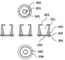
제1도는 상하 이동과 소캡(200)을 지탱하는 기능을 갖춘 소캡 지탱용 지지대(100)의 단면 전개도로써, 소캡 지탱용 지지대(100)는 탄성이 있는 플라스틱 또는 금속성 재질로 만들어 지며 전체적으로 셔틀 콕(Shuttlecock) 모양과 유사한 형태를 가지고 소캡 지탱용 지지대(100) 몸체 상부에는 지지대 날개(108)가 다수개 구성되어 있으며, 중앙 부에는 니들(N)이 수용되어 있는 막대모양의 돌기가 관통할 수 있도록 상하 원형으로 개구된 원통 모양의 니들 관통 및 수용 고정용 원기둥(106)이 형성되어 있고 상기 소캡 지탱용 지지대(100)는 사용자의 피부에 접촉하여 눌림 압력에 의해 소캡(200)이 중캡(300) 내부에서 하강할 시, 소캡 내부 상단에 형성되어 있는 지지대 이탈방지용 소캡의 상부 턱(202)과 맞닿아 있는 지지대 상단 부(103)에 동일한 눌림 압력의 힘이 전달되어 소캡(200) 내부에 수용된 소캡 지탱용 지지대(100) 역시 소캡(200)과 함께 중캡(300) 내부에서 동반 하강하게 되어 소캡(200)이 중캡(300) 내부에서 하강하는 길이 만큼 니들(N)은 소캡(200) 상단 외부로 들어나게 되어 외부로 들어난 니들(N)의 길이 만큼 피부를 뚫고 들어가 주사약제를 자가투여 할 수 있게 되며 이때 소캡(200)과 함께 하강된 소캡 지탱용 지지대(100)는 지지대와 허브 고정용 홈(109)에 지지대 삽입 고정용 이등면 삼각형 모양의 돌기(402)가 삽입되어 고정체결되어지게 되고 사용자가 자가주사 후, 스프링의 회복 탄력성에 의해 소캡(200)은 중캡(300) 내부에서 상단 방향으로 상승하여 원 위치되어 지나, 소캡 지탱용 지지대(100)는 소캡(200)과 함께 동반 상승하지 못하고 상승 완료된 소캡(200) 하단 저면부에 형성된 지지대 지탱용 원형 띠 모양의 돌기(205) 안쪽 면을 지지대 상단 부(103)가 떠받치게 되어 1회 하강되었던 소캡(200)이 재차 하강되는 것을 막아 펜니들(N)의 재사용을 불가능하게 만든다.1 is a sectional top view of a small-
제2도는 제1도의 소캡 지탱용 지지대(100)를 수용하며 사용자의 주사약제 투여 시 피부와 직접적으로 접촉되어 눌림 압력에 의해 중캡(300) 내부에서 하강이동하고 주사 후 다시 스프링의 회복 탄력성에 의해 중캡(300) 내부에서 다시 상승 이동하는 소캡(200)의 단면 전개도로써,FIG. 2 shows a state in which the small-
상하 원형으로 개구된 원통모양의 소캡(200)의 하단 외부에는 원형 띠 모양의 돌기(206)가 둘러져 있어 소캡(200)이 중캡(300) 내부의 지지대 및 소캡, 중캡, 허브, 스프링 수용 구(303)에서 사용자의 소캡(200) 눌림 압력과 스프링의 탄력성에 의해 상하왕복 이동할 시 중캡(300)의 내 벽면에 매끄럽게 지지되어 소캡(200)이 균형 잡힌 상태로 상하 왕복운동을 가능하게 하며,Shaped
무엇보다도 중캡(300) 내부에 스프링의 탄성에 의해 떠 받쳐 올려져 있는 소캡(200)이 중캡(300) 상단의 소캡 원판 형 돌기 지탱용 턱(301)에 원판 형 돌기(206)가 걸리게 되어 소캡(200)이 중캡(300) 외부로 이탈되지 않게 되며 소캡(200)의 저 면에는 원판 형 돌기(206)의 지름보다 작고 스프링의 내경 지름 보다도 작게 지지대 날개(108) 지탱 용도인 원판 형 돌기(205)가 형성되어 있어 사용자가 펜니들을 한번 사용 후 중캡(300) 내부에서 지지대 날개(108)가 소캡(200)을 떠 받쳐 올려졌을 때, 외부로부터 소캡(200)을 누르는 힘에 대응하여 지지대 상단 부(103)가 벌어져 이탈되는 것을 막고 지지대 날개에 전달되어지는 힘이 분산되는 것을 막아주는 역할을 하게 된다.Above all, the small cap (200) supported by the elasticity of the spring inside the middle cap (300) is caught by the disk-shaped projection (206) on the small cap-like disk-shaped projection supporting jaw (301) Shaped
또한, 소캡(200) 상단 부에 형성되어 있는 원형 개구는 소캡(200) 내부의 지름보다는 작게 형성되고 허브 중심부에 구비된 니들(N) 수용 및 고정용 원기둥(404)의 외경 지름보다는 크게 형성되어 있어 니들(N) 수용 및 고정용 원기둥(404)으로부터 자유스럽게 왕복이동이 가능한 반면, 소캡(200) 내부에 수용되어 있는 소캡 지탱용 지지대(100)는 지지대 상단 부(103)와 지지대 이탈방지용 소캡의 상부 턱(202) 안쪽과 맞 닿아 있어 소캡(200)이 하강 이동할 시에는 소캡(200) 지지대 수용부(201)에 수용되어 있는 소캡 지탱용 지지대(100)도 함께 하강 이동하게 된다.The circular opening formed in the upper end of the
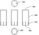
제3도는 제2도의 소캡(200)을 수용하는 중캡(300)의 단면 전개도로써, 원통 형 모양의 중캡(300)은 상하 원형으로 개구되어 있고 중캡(300)의 상단의 원형 개구는 중캡(300) 내부의 지름보다는 작고 소캡(200)의 외경 지름보다는 크게 형성되어 소캡 원판 형 돌기 지탱용 턱(301)을 구성하되 소캡(200)의 원판 형 돌기(206)의 지름보다는 작게 형성되어 소캡(200)이 스프링의 탄성에 의해 중캡(300) 상단 외부로 이탈되는 것을 막는 구조를 띄며,3 is a sectional top view of the
중캡(300)의 내부 하단 면에는 허브(400)와 체결되어 일체를 이룰 수 있는 역 이등변 삼각형 모양의 허브 체결용 돌기(302)가 형성되어 있고 중캡(300)은 내부에는 소캡 지탱용 지지대(100)와, 소캡 지탱용 지지대(100)를 수용하고 있는 소캡(200)과 니들(N) 수용 및 고정용 원기둥(404) 및 스프링을 모두 수용할 수 있는 구조와 형태로 구성된다.The
제4도는 허브(400) 중심부에 앞 니들(N) 수용 및 고정용 원기둥(404)이 구비되고 펜 타입 주사기의 주사약제 수용체 상부의 허브 체결용 나사산(601)과 체결될 수 있도록 내부에 주사약제 수용체 상부의 허브 체결용 나사산(407)을 구비한 허브의 단면 전개도로써, 허브(400)에는 중캡(300)과 체결되어 일체가 되도록 만들기 위하여 허브 체결용 돌기(302)가 삽입 체결되는 중캡 돌기 체결용 수용 구(406)가 형성되어 있고 허브(400) 중심부에는 니들(N)이 니들(N) 관통 및 삽입 구(406)를 통하여 관통 삽입되고 본딩에 의해 고정 장착되는 막대모양의 니들(N) 수용 및 고정용 원기둥(404)이 구비되어 있고 상기 니들(N) 수용 및 고정용 원기둥(404) 하단 부에는 소캡 지탱용 지지대(100)의 하단부에 형성되어 있는 지지대와 허브 고정용 홈(109)에 삽입되어 결합되는 지지대 삽입 고정용 이등변 삼각형 모양의 돌기(402)가 형성되어 있고 스프링을 수용할 수 있는 공간인 스프링 삽입 및 수용 구(403)가 구비되어 있으며,4 shows a state in which a
허브(400) 하부 외벽 면에는 대캡(500) 내부 하단 벽면에 형성되어 있는 허브 수용 유도체결용 막대모양의 돌기(503)와 엇갈려 대캡(500) 내부로 허브(400)의 삽입 수용을 용이하게 하고 정확한 삽입 방향으로 유도하는 대캡 삽입 체결용 막대모양의 돌기(408)가 일정한 간격으로 띠를 둘러 형성되어 있으며 허브(400) 내부 내면에는 펜 타입 주사기의 주사약제 수용체 상부의 허브 체결용 나사산(601)과 나사체결 방식으로 체결될 수 있도록 주사약제 수용체 상부 나사산 체결용 나사산(407)을 구비하고 있다.The
제5도는 상기 제4도의 허브(400)에 니들(N)이 장착되기 전의 모양과 장착된 모양을 비교한 단면도로써, 통상적으로 니들(N) 수용 및 고정용 원기둥(404) 외부로 노출되는 니들(N)을 앞 니들(N)이라고 통칭하며 허브 내부에 위치되면서 펜 타입 주사기 본체(605)의 주사약제 수용체(602) 내부로 삽입되는 니들(N)을 뒷 니들이라고 통칭한다.5 is a cross-sectional view comparing the shape of the
제6도는 대캡(500)의 단면 전개도로써, 전체적으로 원기둥 형태를 보이며 대캡 상단(501)은 막혀 있고 하단에는 대캡 하단 개구 부(504)가 형성되어 있으며 소캡 지탱용 지지대(100)를 수용하고 있는 소캡(200)과 중캡(300) 및 허브(400)를 모두 수용하는 허브 조립 체 수용 부(502)가 구비되고 대캡 하단 개구 부(504) 저면에 멸균 마감지로 압착 밀봉하여 E.O 가스로 최종 멸균한다.6 is a sectional top view of the
제7도는 펜 타입 주사기의 일반적인 모양과 형태를 나타낸 모양도로서, 보통의 펜 타입 주사기는 펜 타입 주사기 덮개(600)와 펜 타입 주사기 본체(605)로 구성되며 펜 타입 주사기 본체(605) 내부에는 주사약제가 수용되는 주사약제 수용체(602)가 구비되며 상기 주사약제 수용체(602)에는 허브(400)와 나사체결 방식으로 결합할 수 있는 주사약제 수용체 상부의 허브 체결용 나사산(601)이 구비됨과 더불어 주사약제 사용량을 확인할 수 있는 주사약제 사용량 눈금(603)이 표식 되어 있으며 의사의 처방에 의한 주사약제 투여 량을 세팅할 수 있는 주사약제 세팅 확인용 눈금 창(606)과 주사약제 세팅용 돌림 레버(608)로 구성되어 있고 펜니들을 체결 결합한 이후 세팅된 주사약제를 주사 투여할 수 있는 주사약제 투여용 누름 버튼(609)로 구성되어 진다.The pen type syringe is composed of a pen
제8도는 본 발명의 각 구성 품들의 조립 순서를 나타낸 이해도로써 먼저 소캡 지탱용 지지대(100)를 지지대 이탈방지용 소캡의 상부 턱(202)로 삽입하여 합체 시키고 소캡 지탱용 지지대(100)를 수용하게된 소캡(200)을 중캡(300) 내부에 마련된 지지대(100) 및 소캡(200), 중캡(300), 허브(400), 스프링 수용 구(303)를 통과 삽입하여 수용시킨 다음 스프링을 삽입시키고 이어서 니들(N)이 장착된 허브(400)를 삽입시켜 중캡(300)의 허브 체결용 돌기(302)와 허브(400)의 중캡 돌기 체결용 수용 구(406)를 이용하여 체결 결합하여 일체를 이루도록 패키지화 하여 본 발명인 펜니들에 대한 안전보호시스템을 완성하고 펜니들을 대캡(500) 하단 개구부(504) 방향으로 허브 수용 유도체결용 막대모양의 돌기(503)와 대캡 삽입 체결용 막대모양의 돌기(408)가 서로 엇갈려 고정 삽입될 수 있도록 삽입하여 수용 안착시킨 다음 대캡(500) 하단 개구부(504)를 멸균 마감지로 밀봉하고 E.O가스 멸균공정을 거쳐 제품화 한다.8 is a perspective view of assembling steps of the components of the present invention. First, the small-
제9도는 본 발명의 사용에 따른 동작과 기능을 이해할 수 있는 가상 순서도로써 맨 좌측의 그림은, 본 발명인 안전보호시스템을 갖춘 펜니들이 사용자의 피부에 접촉되어 니들(N)이 소캡(200) 외부로 들어나기 직전의 모양을 나타낸 것이며,FIG. 9 is a phantom flow diagram for understanding the operation and function of the present invention. FIG. 9 is a left side view showing a state where a pen needle having a safety protection system according to the present invention is brought into contact with a skin of a user, And the shape of the surface immediately before entering,
두 번째 그림은, 사용자가 본 안전보호시스템을 갖춘 펜니들을 피부에 접촉시킨 다음 누름 압력에 의해 소캡(200)이 중캡(300) 내부의 지지대(100) 및 소캡(200), 중캡(300), 허브(400), 스프링 수용 구(303)로 하강 이동되고 하강 이동된 길이 만큼 앞 니들(N)이 피부 속으로 인입되어 주사약제를 주사 투여할 수 있는 상태를 나타낸 그림이며,In the second figure, after the user touches the skin with the pen with the safety protection system, the pushing pressure causes the
세 번째 그림은, 사용자가 두 번째 그림에서와 같은 상태에서 주사약제 투영용 누름 버튼(609)을 눌러 자가주사 투여한 이후 피부로부터 이격시키는 중간 과정을 나타낸 그림으로써 셔틀 콕(Shuttlecock) 모양의 소캡 지탱용 지지대(100)에 구비된 지지대와 허브 고정용 홈(109)에 지지대 삽입 고정용 이등변 삼각형 모양의 돌기(402)가 삽입 고정 장착되어져 스프링의 탄성에 의해 소캡(200)만 소캡(200) 원판 형 돌기 지탱용 턱(301)까지 원 위치로 상승 이동할 시 탄성 있는 재질의 지지대 상단 부(103)가 오므라져 소캡(200)에서 빠져 나와 분리되어 지는 중간 과정의 모양을 가상한 것이며,The third figure shows an intermediate process in which the user removes the skin from the skin after self-injection by pushing the
네 번째 그림은, 스프링의 회복 탄력성에 의해 중캡(300) 내부에서 원판형 돌기 지탱용 턱(301)까지 완전히 들어 올려진 소캡(200)과 이로 인해 소캡(200)의 지지대 수용 부(201) 내부에 수용되어 있던 탄성 있는 재질의 지지대 상단 부(103)가, 소캡(200) 하단의 지지대 관통용 개구(204)로부터 완전히 분리되어 이탈하면서 자체 탄성에 의해 다시 펼쳐진 셔틀 콕(Shuttlecock) 모양으로 복원되어 소캡(200) 하단 부의 지지대 지탱용 원형 띠 모양의 돌기(205)저 면을 떠 받쳐 지탱하게 되어 소캡(200)이 더 이상 외부의 누름 압력에 의해 재차 하강되지 못하게 되는 모양을 나타낸 가상도이다.The fourth figure shows a state where the
제10도는 펜 타입주사기와 본 발명인 안전보호시스템을 갖춘 펜니들의 실시를 이해하기 위한 가상도로써, 먼저 펜 타입 주사기 본체(605)에서 펜 타입 주사기 덮개(600)를 분리한 다음 본 발명인 펜니들에 대한 안전보호시스템에서 멸균 마감지를 제거 한 이후 펜 타입 주사기 본체(605)의 주사약제 수용체(602) 상단에 형성된 주사약제 수용체 상부의 허브 체결용 나사산(601)에 나사체결방식으로 체결 결합하여 제9도에서와 같은 절차와 과정를 통해 주사약제를 자가주사 투여한 다음 본 발명인 펜니들에 대한 안전보호시스템을 상기 나사체결방식과 반대 반대 방향인 나사풀림방식으로 분리하는 과정을 설명한 것이며, 이렇게 1회 사용되어진 펜니들에 대한 안전보호시스템은 안전하게 폐기처리되며 사용자는 펜 타입 주사기 덮개(600)를 펜 타입 주사기의 본체(605)에 결합하여 다음 사용시 까지 보관하게 된다.
10 is a virtual view for understanding the implementation of a pen type syringe and a pen needle having the safety protection system of the present invention. First, the pen
100: 소캡 지탱용 지지대
101: 지지대 본체와 지지대 연결 부위
102: 지지대 하단 부
103: 지지대 상단 부
104: 지지대 하단 돌출 돌기
105: 지지대 내면
106: 니들 관통 및 수용 고정용 원기둥
107: 지지대 하부 원기둥 형 몸통
108: 지지대 날개
109: 지지대와 허브 고정용 홈
110: 지지대 외면
200: 소캡
201: 지지대(100) 수용 부
202: 지지대(100) 이탈 방지용 소캡의 상부 턱
203: 지지대(100) 이동 및 관통 구
204: 지지대 관통용 개구
205: 지지대(100) 지탱용 원형 띠 모양의 돌기
206: 원판 형 돌기
300: 중캡
301: 소캡(200) 원판 형 돌기(206) 지탱용 턱
302: 허브 체결용 돌기
303: 지지대(100) 및 소캡(200), 중캡(300), 허브(400), 스프링 수용 구
400: 허브
401: 중캡(300) 삽입 및 고정용 원 기둥
402: 지지대(100) 삽입 고정용 이등변 삼각형 모양의 돌기
403: 스프링 삽입 및 수용 구
404: 니들(N) 수용 및 고정용 원기둥
405: 니들(N) 관통 및 수용 구
406: 중캡 돌기(302) 체결용 수용 구
407: 주사약제 수용체 상부 나사산(601) 체결용 나사산
408: 대캡 삽입 체결용 막대모양의 돌기
500: 대캡
501: 대캡 상단
502: 허브 조립 체 수용 부
503: 허브 수용 유도체결용 막대모양의 돌기
504: 대캡 하단 개구 부
600: 펜 타입 주사기 덮개
601: 주사약제 수용체 상부의 허브 체결용 나사산
602: 주사약제 수용체
603: 주사약제 사용량 눈금
604: 덮개 고정용 막대모양의 돌기
605: 펜 타입 주사기 본체
606: 주사약제 세팅 확인용 눈금 창
607: 주사약제 세팅 눈금 기준 표식
608: 주사약제 세팅용 돌림 레버
609: 주사약제 투여용 누름 버튼100: Small-cap support support
101: connecting portion between the support body and the support portion
102: lower end of the support
103: upper end of support
104: Lower protrusion protrusion
105: inner surface of the support
106: Needle penetration and receiving cylinder
107: Support base Lower cylindrical body
108: support blade
109: Supporting base and hub fixing groove
110:
200: small cap
201: support base (100)
202: Upper jaw of the small cap for preventing separation of the support base (100)
203: support (100) movement and through hole
204: opening for supporting support
205: Support base (100) Supporting circular band-like projection
206: disk-like projection
300: Medium cap
301: Small cap (200) disk-like projection (206) Supporting jaw
302: Hub fastening projection
303: a
400: Hub
401: Cylinder for insertion and fixing of the middle cap (300)
402: support (100) isosceles triangular projection for insertion and fixing
403: Spring insertion and receptacle
404: Needle (N) Cylinder for receiving and fixing
405: Needle (N) penetration and receptacle
406: Middle cap projection 302: Fastening receptacle
407: Injection drug receptor top thread (601) Fastening thread
408: rod-shaped protrusion for insertion of large-cap
500: Large cap
501: Large cap upper
502: hub assembly holding portion
503: rod-shaped projection for induction of hub reception
504: large-cap bottom opening
600: pen type syringe cover
601: Hub fastening thread on top of injection drug receptor
602: injection drug receptor
603: Injection dosage scales
604: Bar-shaped projection for fixing the cover
605: Pen type syringe body
606: Scale window for confirmation of injection drug setting
607: Injectable drug setting scale reference mark
608: Turning lever for injecting drug setting
609: push button for injecting medicine
Claims (4)
Translated fromKorean니들(N)을 구비한 허브(400)의 상단 부에 스프링과 소캡 지지용 지지대(100)와 소캡(200)을 수용하는 중캡(300)이 구성되고, 소캡(200) 내부에 탄성을 갖춘 재질로 제작된 셔틀 콕(Shuttlecock) 모양의 소캡 지탱용 지지대(100)는 사용자가 피부와 접촉되는 소캡(200) 상면의 눌림 압력에 의하여 눌러져 소캡 지탱용 지지대(100) 역시 소캡(200)과 함께 중캡 내부로 동반 하강 이동되게 되나, 소캡 지탱용 지지대(100)만 허브에 형성된 지지대 삽입 고정용 이등변 삼각형 모양의 돌기(402)에 의해 고정되어 지고, 스프링의 회복 탄력성에 의해, 상기 소캡 지탱용 지지대(100)를 제외한 소캡(200)만 사용 전 위치인 중캡(300) 내부의 상단으로 원 위치되기 위해 상승 이동하게 되며,
스프링의 회복 탄력성에 의해 소캡(200)만 상승 이동하게 될 시 허브에 형성된 지지대 삽입 고정용 이등변 삼각형 모양의 돌기(402)에 의해 고정되어진 소캡 지탱용 지지대(100)에 형성된 다수 개의 지지대 상단 부(103)는 지지대 관통용 개구(204)를 빠져 나올 때에는 모아져서 미끄러지 듯 빠져 나오게 되고, 소캡 지탱용 지지대(100)의 지지대 상단 부(103)가 소캡(200)의 지지대 관통용 개구(204)와 완전히 분리되는 순간 모아 졌던 지지대 상단 부(103)는 자체 탄성에 의해 다시 펼쳐져 소캡(200)의 저 면부를 지탱하게 되어 소캡(200)이 재차 중캡(300) 내부로 하강 이동하는 것을 막아 소캡(200) 내부에 수용되어 있는 앞 니들(N)이 소캡(200) 외부로 들어나지 못하게 되어 재사용을 불가능하게 하는 것을 특징으로 하는 안전보호시스템을 갖춘 펜니들.
In order to prevent the risk of infection due to reuse by having a structure that can not be reused after a single use by the user, the pen needle which is used for one time use in combination with a pen type syringe used for various purposes, As a matter of fact,
A center cap 300 for accommodating a spring and a small cap supporting support 100 and a small cap 200 is formed at an upper end portion of a hub 400 having a needle N. Inside the small cap 200, A support bolt 100 for supporting a small-cap in the form of a shuttlecock is pressed by the pressure of the upper surface of the small cap 200 which is in contact with the user's skin, Only the small-cap supporting supporter 100 is fixed by the isosceles triangular protrusion 402 for inserting and fixing the supporter formed on the hub, and the resilient elasticity of the spring fixes the small-cap supporting supporter 100 Only the small-sized cap 200 except the small-sized cap 100 moves upward to be positioned at the top of the inside of the middle-sized cap 300,
A plurality of supporter top portions (not shown) formed on the supporter 100 for supporting the small caps fixed by the isosceles triangular protrusions 402 for inserting and fixing the supporters formed on the hub when the small caps 200 are lifted due to the resilience of the springs The support base upper end portion 103 of the small-cap support base 100 is slidably received in the support base through-opening 204 of the small-cap 200, The support upper end portion 103 that has been collected at the moment of complete separation is unfolded by the self-elasticity to support the bottom surface portion of the small cap 200 to prevent the small cap 200 from moving downward again into the middle cap 300, , The front needle (N) housed in the inside of the small cap (200) can not enter the outside of the small cap (200), thereby making it impossible to reuse the pen.
탄성이 있는 플라스틱 또는 금속성 재질의 셔틀 콕(Shuttlecock) 모양의 소캡 지탱용 지지대(100)는 다수개의 지지대 날개(108)로 구성되며 사용 전에는 소캡(200) 내부에 위치하여 보관되어 있고, 사용 후에는 지지대 삽입 고정용 이등변 삼각형 모양의 돌기(402)에 고정되어 스프링의 회복 탄력성에 의해 소캡(200)과 분리되어 중캡 내부에 위치하면서 소캡(200)의 하강을 지탱하게 되어 소캡(200)이 재차 중캡(300) 내부로 하강 이동하는 것을 방지하여 펜니들의 재사용을 불가능하게 하는 것을 특징으로 하는 안전보호시스템을 갖춘 펜니들.
The method according to claim 1,
The small-cap supporting support 100 in the form of an elastic plastic or metallic shuttlecock is composed of a plurality of supporting wings 108 and is stored in the small-sized cap 200 before use, Shaped protuberance 402 for fixing the support member and separated from the small cap 200 by the resilience of the spring to support the descent of the small cap 200 while being positioned inside the middle cap, (300), thereby preventing reuse of the pen needle. ≪ RTI ID = 0.0 > 31. < / RTI >
소캡(200)의 상하 이동에 관여하는 탄성 있는 스프링은 중캡(300) 내부에 수용되어 있는 것을 특징으로 하는 안전보호시스템을 갖춘 펜니들.The method of claim 2,
Wherein a resilient spring that is involved in up and down movement of the small cap (200) is housed inside the middle cap (300).
Priority Applications (7)
| Application Number | Priority Date | Filing Date | Title |
|---|---|---|---|
| KR1020150145029AKR101589006B1 (en) | 2015-10-17 | 2015-10-17 | Safety protection system for pen needles |
| US15/548,674US10576219B2 (en) | 2015-10-17 | 2016-06-30 | Pen needle provided with safety protection system |
| CN201680013014.4ACN107405460B (en) | 2015-10-17 | 2016-06-30 | Pen needle with safety protection system |
| EP16855604.1AEP3363484B1 (en) | 2015-10-17 | 2016-06-30 | Pen needle provided with safety protection system |
| PL16855604.1TPL3363484T3 (en) | 2015-10-17 | 2016-06-30 | Pen needle provided with safety protection system |
| PCT/KR2016/007003WO2017065386A1 (en) | 2015-10-17 | 2016-06-30 | Pen needle provided with safety protection system |
| DK16855604.1TDK3363484T3 (en) | 2015-10-17 | 2016-06-30 | PEN CANNULE EQUIPPED WITH SAFETY PROTECTION SYSTEM |
Applications Claiming Priority (1)
| Application Number | Priority Date | Filing Date | Title |
|---|---|---|---|
| KR1020150145029AKR101589006B1 (en) | 2015-10-17 | 2015-10-17 | Safety protection system for pen needles |
Publications (1)
| Publication Number | Publication Date |
|---|---|
| KR101589006B1true KR101589006B1 (en) | 2016-02-12 |
Family
ID=55355157
Family Applications (1)
| Application Number | Title | Priority Date | Filing Date |
|---|---|---|---|
| KR1020150145029AActiveKR101589006B1 (en) | 2015-10-17 | 2015-10-17 | Safety protection system for pen needles |
Country Status (7)
| Country | Link |
|---|---|
| US (1) | US10576219B2 (en) |
| EP (1) | EP3363484B1 (en) |
| KR (1) | KR101589006B1 (en) |
| CN (1) | CN107405460B (en) |
| DK (1) | DK3363484T3 (en) |
| PL (1) | PL3363484T3 (en) |
| WO (1) | WO2017065386A1 (en) |
Cited By (7)
| Publication number | Priority date | Publication date | Assignee | Title |
|---|---|---|---|---|
| WO2017065386A1 (en)* | 2015-10-17 | 2017-04-20 | 주식회사 메덱셀 | Pen needle provided with safety protection system |
| KR101774165B1 (en) | 2016-08-01 | 2017-09-01 | 박기범 | Safety protection system is equipped with a disposable pen needle |
| KR20180072173A (en)* | 2016-12-21 | 2018-06-29 | 인제대학교 산학협력단 | Non-reusable syringe |
| KR102047126B1 (en)* | 2019-03-12 | 2019-11-20 | 주식회사 메덱셀 | Safety pen needle capable of preventing loose rotation |
| WO2020184861A1 (en)* | 2019-03-12 | 2020-09-17 | 주식회사 메덱셀 | Pen needle |
| KR102160921B1 (en)* | 2020-04-20 | 2020-10-05 | 주식회사 필텍바이오 | Safety pen-needle |
| KR102381715B1 (en)* | 2021-11-22 | 2022-04-01 | (주)풍림파마텍 | Injection device to prevent needle reuse |
Families Citing this family (4)
| Publication number | Priority date | Publication date | Assignee | Title |
|---|---|---|---|---|
| CN210785700U (en)* | 2018-04-27 | 2020-06-19 | 贝克顿·迪金森公司 | Container for storing pen needle |
| FR3087116B1 (en)* | 2018-10-10 | 2024-06-21 | Crossject | DEVICE FOR HOLDING INJECTION DEVICE TUBES |
| CN109718429B (en)* | 2019-02-15 | 2024-01-16 | 贝普医疗科技股份有限公司 | Safety insulin needle |
| US12005244B2 (en) | 2020-03-27 | 2024-06-11 | Medivena Sp. Z O.O. | Needle-based device based on direct wing-based coupling of a needle shield to a barrel thereof and safety mechanism implemented therein |
Citations (2)
| Publication number | Priority date | Publication date | Assignee | Title |
|---|---|---|---|---|
| KR940006609A (en)* | 1992-09-08 | 1994-04-25 | 남영희 | Safety cap of disposable syringe |
| KR20000020090A (en)* | 1998-09-17 | 2000-04-15 | 구자홍 | Method and apparatus for detecting wind pressure of gas heater |
Family Cites Families (24)
| Publication number | Priority date | Publication date | Assignee | Title |
|---|---|---|---|---|
| US6015397A (en)* | 1997-06-20 | 2000-01-18 | Elson; Edward E. | Needle point guard safety cap assembly |
| IT1304761B1 (en)* | 1998-01-20 | 2001-03-29 | Nardino Righi | DISPOSABLE SAFETY SYRINGE. |
| JP4348578B2 (en)* | 1999-04-26 | 2009-10-21 | 株式会社ジェイ・エム・エス | Wing needle device |
| KR20000020090U (en)* | 1999-04-28 | 2000-11-25 | 이상헌 | Once-used ingector |
| DE10009814B4 (en) | 2000-03-01 | 2008-03-06 | Tecpharma Licensing Ag | Disposable injector |
| EP1138338A1 (en) | 2000-03-20 | 2001-10-04 | Becton Dickinson and Company | Medical safety disposal cap assembly |
| US6547764B2 (en)* | 2000-05-31 | 2003-04-15 | Novo Nordisk A/S | Double pointed injection needle |
| FR2832932A1 (en)* | 2001-11-30 | 2003-06-06 | Endos Pharma | SAFETY DEVICE FOR PARENTERAL INJECTION SYRINGE, SINGLE USE |
| WO2005079440A2 (en)* | 2004-02-17 | 2005-09-01 | Children's Hospital Medical Center | Improved injection devicew for administering a vaccine |
| KR100618076B1 (en)* | 2006-05-10 | 2006-08-29 | 김근식 | Disposable Auto Safety Syringe |
| TW200743500A (en) | 2006-05-26 | 2007-12-01 | ming-zheng Xu | Disposable syringe |
| DE102006041809B4 (en)* | 2006-09-06 | 2012-11-15 | Tecpharma Licensing Ag | Needle protection device with blocking device |
| DE102006042236A1 (en)* | 2006-09-06 | 2008-03-27 | Tecpharma Licensing Ag | Needle guard with blocked guard position |
| CA2714621C (en) | 2008-02-15 | 2017-08-15 | Stephen Lynn Richards | Safety pen needle assembly |
| WO2009148969A1 (en)* | 2008-06-02 | 2009-12-10 | Sta-Med, Llc | Needle cover assembly for a syringe |
| EP3960224A1 (en) | 2008-08-15 | 2022-03-02 | Becton, Dickinson and Company | Safety pen needle assembly |
| US8491535B2 (en) | 2011-04-28 | 2013-07-23 | Becton, Dickinson And Company | Safety pen needle assembly |
| EP2596825A1 (en)* | 2011-11-24 | 2013-05-29 | Sanofi-Aventis Deutschland GmbH | Needle assembly attachment and removal device |
| JP6240183B2 (en)* | 2012-06-29 | 2017-11-29 | ノボ・ノルデイスク・エー/エス | Shield lock for spring driven injection device |
| EP2878319A1 (en)* | 2013-11-28 | 2015-06-03 | Sanofi-Aventis Deutschland GmbH | Boot remover |
| ES2863959T3 (en) | 2013-12-10 | 2021-10-13 | Becton Dickinson Co | Active Safety Pen Needle Assembly |
| EP2944340A1 (en)* | 2014-05-12 | 2015-11-18 | Sanofi | Activating mechanism for a medicament delivery device and medicament delivery device |
| CN104436369A (en)* | 2014-12-30 | 2015-03-25 | 江苏华阳电器有限公司 | Implicit needle mechanism of injector |
| KR101589006B1 (en)* | 2015-10-17 | 2016-02-12 | 주식회사 메덱셀 | Safety protection system for pen needles |
- 2015
- 2015-10-17KRKR1020150145029Apatent/KR101589006B1/enactiveActive
- 2016
- 2016-06-30CNCN201680013014.4Apatent/CN107405460B/enactiveActive
- 2016-06-30PLPL16855604.1Tpatent/PL3363484T3/enunknown
- 2016-06-30EPEP16855604.1Apatent/EP3363484B1/enactiveActive
- 2016-06-30USUS15/548,674patent/US10576219B2/enactiveActive
- 2016-06-30WOPCT/KR2016/007003patent/WO2017065386A1/ennot_activeCeased
- 2016-06-30DKDK16855604.1Tpatent/DK3363484T3/enactive
Patent Citations (2)
| Publication number | Priority date | Publication date | Assignee | Title |
|---|---|---|---|---|
| KR940006609A (en)* | 1992-09-08 | 1994-04-25 | 남영희 | Safety cap of disposable syringe |
| KR20000020090A (en)* | 1998-09-17 | 2000-04-15 | 구자홍 | Method and apparatus for detecting wind pressure of gas heater |
Cited By (10)
| Publication number | Priority date | Publication date | Assignee | Title |
|---|---|---|---|---|
| WO2017065386A1 (en)* | 2015-10-17 | 2017-04-20 | 주식회사 메덱셀 | Pen needle provided with safety protection system |
| US10576219B2 (en) | 2015-10-17 | 2020-03-03 | Medexel Co., Ltd. | Pen needle provided with safety protection system |
| KR101774165B1 (en) | 2016-08-01 | 2017-09-01 | 박기범 | Safety protection system is equipped with a disposable pen needle |
| KR20180072173A (en)* | 2016-12-21 | 2018-06-29 | 인제대학교 산학협력단 | Non-reusable syringe |
| KR101879075B1 (en)* | 2016-12-21 | 2018-07-16 | 인제대학교 산학협력단 | Non-reusable syringe |
| KR102047126B1 (en)* | 2019-03-12 | 2019-11-20 | 주식회사 메덱셀 | Safety pen needle capable of preventing loose rotation |
| WO2020184861A1 (en)* | 2019-03-12 | 2020-09-17 | 주식회사 메덱셀 | Pen needle |
| CN113557047A (en)* | 2019-03-12 | 2021-10-26 | 梅德塞尔有限公司 | Pen type needle |
| KR102160921B1 (en)* | 2020-04-20 | 2020-10-05 | 주식회사 필텍바이오 | Safety pen-needle |
| KR102381715B1 (en)* | 2021-11-22 | 2022-04-01 | (주)풍림파마텍 | Injection device to prevent needle reuse |
Also Published As
| Publication number | Publication date |
|---|---|
| WO2017065386A1 (en) | 2017-04-20 |
| US20180028764A1 (en) | 2018-02-01 |
| EP3363484B1 (en) | 2022-10-12 |
| CN107405460A (en) | 2017-11-28 |
| DK3363484T3 (en) | 2022-10-31 |
| US10576219B2 (en) | 2020-03-03 |
| CN107405460B (en) | 2020-05-19 |
| EP3363484A1 (en) | 2018-08-22 |
| EP3363484A4 (en) | 2019-06-26 |
| PL3363484T3 (en) | 2023-01-02 |
Similar Documents
| Publication | Publication Date | Title |
|---|---|---|
| KR101589006B1 (en) | Safety protection system for pen needles | |
| JP6815370B2 (en) | Palm-operated drug delivery device | |
| TW315305B (en) | ||
| KR0158446B1 (en) | Dosing device | |
| JP2008220949A (en) | Injector for use together with pre-filled syringe and method of assembly | |
| KR102751238B1 (en) | medical injector cap | |
| CN102341139B (en) | Cap lock | |
| KR101604957B1 (en) | Pen needle has the function can be clipped and ejected by one-touch for pen-type syringe and pen cover cap has the function can be disposed by one-touch operation | |
| CN112312945A (en) | Device for injecting medicine and method of use | |
| CN108290008B (en) | Cap with hemispherical portion for medical injector | |
| KR200494659Y1 (en) | Pen-type syringe hub | |
| EP3216474B1 (en) | Safety injection needle device | |
| CN109172954A (en) | A kind of snap-type novopen needle | |
| KR101879976B1 (en) | Cover for Pen type Syringe | |
| KR102181488B1 (en) | T-shaped cap for medical injector | |
| CN213252098U (en) | Pen needle | |
| KR200473461Y1 (en) | Insulin Syringe Needle | |
| KR20190002857U (en) | Safety pen needle | |
| KR200481093Y1 (en) | Removing the safety pen needle ejecting mechanism | |
| KR200432171Y1 (en) | Insulin safety syringe for needle length adjustment | |
| KR101845655B1 (en) | Safety Cover for Pen type Syringe | |
| KR102250909B1 (en) | One click pen needle for Pen type Syringe | |
| WO2016087188A1 (en) | Needle assembly with needle hub shielding a needle cannula | |
| JP2013517072A (en) | Automatic retractable non-liquid substance safety injection device | |
| CN116870299B (en) | A safe and convenient insulin injection pen |
Legal Events
| Date | Code | Title | Description |
|---|---|---|---|
| PA0109 | Patent application | Patent event code:PA01091R01D Comment text:Patent Application Patent event date:20151017 | |
| PA0201 | Request for examination | ||
| PA0302 | Request for accelerated examination | Patent event date:20151018 Patent event code:PA03022R01D Comment text:Request for Accelerated Examination Patent event date:20151017 Patent event code:PA03021R01I Comment text:Patent Application | |
| PE0902 | Notice of grounds for rejection | Comment text:Notification of reason for refusal Patent event date:20151118 Patent event code:PE09021S01D | |
| E701 | Decision to grant or registration of patent right | ||
| GRNT | Written decision to grant | ||
| PE0701 | Decision of registration | Patent event code:PE07011S01D Comment text:Decision to Grant Registration Patent event date:20160120 | |
| PR0701 | Registration of establishment | Comment text:Registration of Establishment Patent event date:20160120 Patent event code:PR07011E01D | |
| PR1002 | Payment of registration fee | Payment date:20160120 End annual number:3 Start annual number:1 | |
| PG1601 | Publication of registration | ||
| FPAY | Annual fee payment | Payment date:20190110 Year of fee payment:4 | |
| PR1001 | Payment of annual fee | Payment date:20190110 Start annual number:4 End annual number:4 | |
| FPAY | Annual fee payment | Payment date:20200110 Year of fee payment:5 | |
| PR1001 | Payment of annual fee | Payment date:20200110 Start annual number:5 End annual number:5 | |
| PR1001 | Payment of annual fee | Payment date:20201218 Start annual number:6 End annual number:6 | |
| PR1001 | Payment of annual fee | Payment date:20211214 Start annual number:7 End annual number:7 | |
| PR1001 | Payment of annual fee | Payment date:20240123 Start annual number:9 End annual number:9 | |
| PR1001 | Payment of annual fee | Payment date:20250123 Start annual number:10 End annual number:10 |