KR101586318B1 - Method for transmitting and receiving uplink signal, user equipment, and base station - Google Patents
Method for transmitting and receiving uplink signal, user equipment, and base stationDownload PDFInfo
- Publication number
- KR101586318B1 KR101586318B1KR1020137032599AKR20137032599AKR101586318B1KR 101586318 B1KR101586318 B1KR 101586318B1KR 1020137032599 AKR1020137032599 AKR 1020137032599AKR 20137032599 AKR20137032599 AKR 20137032599AKR 101586318 B1KR101586318 B1KR 101586318B1
- Authority
- KR
- South Korea
- Prior art keywords
- scell
- group
- anchor
- pucch
- pusch
- Prior art date
- Legal status (The legal status is an assumption and is not a legal conclusion. Google has not performed a legal analysis and makes no representation as to the accuracy of the status listed.)
- Active
Links
Images


Classifications
- H—ELECTRICITY
- H04—ELECTRIC COMMUNICATION TECHNIQUE
- H04J—MULTIPLEX COMMUNICATION
- H04J11/00—Orthogonal multiplex systems, e.g. using WALSH codes
- H04J11/0069—Cell search, i.e. determining cell identity [cell-ID]
- H—ELECTRICITY
- H04—ELECTRIC COMMUNICATION TECHNIQUE
- H04L—TRANSMISSION OF DIGITAL INFORMATION, e.g. TELEGRAPHIC COMMUNICATION
- H04L5/00—Arrangements affording multiple use of the transmission path
- H04L5/0001—Arrangements for dividing the transmission path
- H04L5/0003—Two-dimensional division
- H04L5/0005—Time-frequency
- H04L5/0007—Time-frequency the frequencies being orthogonal, e.g. OFDM(A) or DMT
- H04L5/001—Time-frequency the frequencies being orthogonal, e.g. OFDM(A) or DMT the frequencies being arranged in component carriers
- H—ELECTRICITY
- H04—ELECTRIC COMMUNICATION TECHNIQUE
- H04B—TRANSMISSION
- H04B7/00—Radio transmission systems, i.e. using radiation field
- H04B7/24—Radio transmission systems, i.e. using radiation field for communication between two or more posts
- H04B7/26—Radio transmission systems, i.e. using radiation field for communication between two or more posts at least one of which is mobile
- H04B7/2603—Arrangements for wireless physical layer control
- H—ELECTRICITY
- H04—ELECTRIC COMMUNICATION TECHNIQUE
- H04L—TRANSMISSION OF DIGITAL INFORMATION, e.g. TELEGRAPHIC COMMUNICATION
- H04L5/00—Arrangements affording multiple use of the transmission path
- H04L5/0001—Arrangements for dividing the transmission path
- H04L5/0003—Two-dimensional division
- H04L5/0005—Time-frequency
- H04L5/0007—Time-frequency the frequencies being orthogonal, e.g. OFDM(A) or DMT
- H—ELECTRICITY
- H04—ELECTRIC COMMUNICATION TECHNIQUE
- H04L—TRANSMISSION OF DIGITAL INFORMATION, e.g. TELEGRAPHIC COMMUNICATION
- H04L5/00—Arrangements affording multiple use of the transmission path
- H04L5/003—Arrangements for allocating sub-channels of the transmission path
- H04L5/0053—Allocation of signalling, i.e. of overhead other than pilot signals
- H04L5/0055—Physical resource allocation for ACK/NACK
- H—ELECTRICITY
- H04—ELECTRIC COMMUNICATION TECHNIQUE
- H04W—WIRELESS COMMUNICATION NETWORKS
- H04W72/00—Local resource management
- H04W72/20—Control channels or signalling for resource management
- H—ELECTRICITY
- H04—ELECTRIC COMMUNICATION TECHNIQUE
- H04W—WIRELESS COMMUNICATION NETWORKS
- H04W72/00—Local resource management
- H04W72/20—Control channels or signalling for resource management
- H04W72/21—Control channels or signalling for resource management in the uplink direction of a wireless link, i.e. towards the network
- H—ELECTRICITY
- H04—ELECTRIC COMMUNICATION TECHNIQUE
- H04W—WIRELESS COMMUNICATION NETWORKS
- H04W72/00—Local resource management
- H04W72/20—Control channels or signalling for resource management
- H04W72/23—Control channels or signalling for resource management in the downlink direction of a wireless link, i.e. towards a terminal
- H—ELECTRICITY
- H04—ELECTRIC COMMUNICATION TECHNIQUE
- H04J—MULTIPLEX COMMUNICATION
- H04J2211/00—Orthogonal indexing scheme relating to orthogonal multiplex systems
- H04J2211/003—Orthogonal indexing scheme relating to orthogonal multiplex systems within particular systems or standards
- H04J2211/005—Long term evolution [LTE]
- H—ELECTRICITY
- H04—ELECTRIC COMMUNICATION TECHNIQUE
- H04J—MULTIPLEX COMMUNICATION
- H04J2211/00—Orthogonal indexing scheme relating to orthogonal multiplex systems
- H04J2211/003—Orthogonal indexing scheme relating to orthogonal multiplex systems within particular systems or standards
- H04J2211/006—Single carrier frequency division multiple access [SC FDMA]
- H—ELECTRICITY
- H04—ELECTRIC COMMUNICATION TECHNIQUE
- H04L—TRANSMISSION OF DIGITAL INFORMATION, e.g. TELEGRAPHIC COMMUNICATION
- H04L1/00—Arrangements for detecting or preventing errors in the information received
- H04L1/12—Arrangements for detecting or preventing errors in the information received by using return channel
- H04L1/16—Arrangements for detecting or preventing errors in the information received by using return channel in which the return channel carries supervisory signals, e.g. repetition request signals
- H04L1/18—Automatic repetition systems, e.g. Van Duuren systems
- H04L1/1829—Arrangements specially adapted for the receiver end
- H04L1/1861—Physical mapping arrangements
- H—ELECTRICITY
- H04—ELECTRIC COMMUNICATION TECHNIQUE
- H04W—WIRELESS COMMUNICATION NETWORKS
- H04W56/00—Synchronisation arrangements
- H—ELECTRICITY
- H04—ELECTRIC COMMUNICATION TECHNIQUE
- H04W—WIRELESS COMMUNICATION NETWORKS
- H04W74/00—Wireless channel access
- H04W74/08—Non-scheduled access, e.g. ALOHA
- H04W74/0833—Random access procedures, e.g. with 4-step access
Landscapes
- Engineering & Computer Science (AREA)
- Signal Processing (AREA)
- Computer Networks & Wireless Communication (AREA)
- Databases & Information Systems (AREA)
- Mobile Radio Communication Systems (AREA)
Abstract
Translated fromKoreanDescription
Translated fromKorean본 발명은 무선 통신 시스템에 관한 것이다. 특히, 본 발명은 복수의 셀(Cell)들이 설정(configure)된 반송파 집성 상황 하에서 보다 효과적인 상/하향링크 신호 전송/수신방법 및 전송/수신장치를 제공한다.The present invention relates to a wireless communication system. In particular, the present invention provides a more effective uplink / downlink signal transmission / reception method and a transmission / reception apparatus under a carrier aggregation condition in which a plurality of cells are configured.
일반적인 무선 통신 시스템은 하나의 하향링크(downlink, DL) 대역과 이에 대응하는 하나의 상향링크(uplink, UL) 대역을 통해 데이터 송/수신을 수행(주파수분할듀플렉스(frequency division duplex, FDD) 모드의 경우)하거나, 소정 무선 프레임(Radio Frame)을 시간 도메인(time domain)에서 상향링크 시간 유닛과 하향링크 시간 유닛으로 구분하고, 상/하향링크 시간 유닛을 통해 데이터 송/수신을 수행(시분할듀플렉스(time division duplex, TDD) 모드의 경우)한다. 기지국(base statio, BS)와 사용자기기(user equipment, UE)는 소정 시간 유닛, 예를 들어, 서브프레임(subframe, SF) 단위로 스케줄링된 데이터 및/또는 제어 정보를 송수신한다. 데이터는 상/하향링크 서브프레임에 설정된 데이터 영역을 통해 송수신되고, 제어 정보는 상/하향링크 서브프레임에 설정된 제어 영역을 통해 송수신된다. 이를 위해, 무선 신호를 나르는 다양한 물리 채널이 상/하향링크 서브프레임에 설정된다.A typical wireless communication system performs data transmission / reception through a downlink (DL) band and a corresponding uplink (UL) band (frequency division duplex (FDD) mode Or a predetermined radio frame is divided into an uplink time unit and a downlink time unit in a time domain and data transmission / reception is performed through an uplink / downlink time unit (a time division duplex time division duplex (TDD) mode). A base station (BS) and a user equipment (UE) transmit and receive data and / or control information scheduled for a predetermined time unit, for example, a subframe (SF). Data is transmitted / received through the data area set in the uplink / downlink subframe, and control information is transmitted / received through the control area set in the uplink / downlink subframe. To this end, various physical channels carrying radio signals are set in the uplink / downlink subframe.
한편, 최근 무선 통신 시스템에서, 보다 넓은 주파수 대역을 사용하기 위하여 복수의 상/하향링크 주파수 블록들을 모아 더 큰 상/하향링크 대역폭을 사용하는 반송파 집성(carrier aggregation 또는 bandwidth aggregation) 기술의 도입이 논의되고 있다.Meanwhile, in recent wireless communication systems, introduction of a carrier aggregation or bandwidth aggregation technique using a larger uplink / downlink bandwidth by collecting a plurality of uplink / downlink frequency blocks to use a wider frequency band is discussed .
도 1은 다중 반송파 상황 하에서 통신을 수행하는 예를 나타낸다.1 shows an example of performing communication under a multi-carrier situation.
다중 반송파 시스템 또는 반송파 집성(carrier aggregation, CA) 기술은 광대역 지원을 위해 목표 대역(bandwidth)보다 작은 대역을 가지는 복수의 반송파들을 집성하여 사용하는 기술을 말한다. 반송파 집성은 복수의 반송파 주파수들을 사용하여 하향링크 혹은 상향링크 통신을 수행한다는 점에서, 복수의 직교하는 부반송파들로 분할된 기본 주파수 대역을 하나의 반송파 주파수에 실어 하향링크 혹은 상향링크 통신을 수행하는 OFDM(orthogonal frequency division multiplexing) 기술과 구분된다. 목표 대역보다 작은 대역을 가지는 복수의 반송파들을 집성할 때, 집성되는 반송파의 대역은 기존 시스템과의 호환(backward compatibility)을 위해 기존 시스템에서 사용하는 대역폭으로 제한될 수 있다. 예를 들어, 기존의 LTE 시스템은 1.4, 3, 5, 10, 15, 20MHz의 대역폭을 지원하며, LTE 시스템으로부터 개선된 LTE-A(LTE-Advanced) 시스템은 LTE에서 지원하는 대역폭들만을 이용하여 20MHz보다 큰 대역폭을 지원할 수 있다. 또는 기존 시스템에서 사용하는 대역폭과 상관없이 새로운 대역폭을 정의하여 반송파 집성을 지원할 수 있다. 다중 반송파는 반송파 집성 및 대역폭 집성과 혼용되어 사용될 수 있는 명칭이다. 또한, 반송파 집성은 인접한(contiguous) 반송파 집성과 인접하지 않은(non-contiguous) 반송파 집성을 모두 통칭한다. 참고로, TDD에서 1개의 콤퍼넌트 반송파(component carrier, CC)만이 통신에 사용되는 경우 혹은 FDD에서 1개의 UL CC와 1개의 DL CC만이 통신에 사용되는 경우, 이러한 통신은 단일 반송파 상황 (non-CA) 하에서의 통신에 해당한다.A multi-carrier system or a carrier aggregation (CA) technique refers to a technique for aggregating and using a plurality of carriers having a bandwidth smaller than a target bandwidth for broadband support. Carrier aggregation performs downlink or uplink communication using a plurality of carrier frequencies by performing a downlink or uplink communication on a carrier frequency divided into a plurality of orthogonal subcarriers And orthogonal frequency division multiplexing (OFDM) techniques. When aggregating a plurality of carriers having a bandwidth smaller than the target bandwidth, the band of the aggregated carrier may be limited to the bandwidth used in the existing system for backward compatibility with the existing system. For example, existing LTE systems support bandwidths of 1.4, 3, 5, 10, 15, and 20 MHz, and improved LTE-A (LTE-Advanced) systems from LTE systems use only the bandwidths supported by LTE It can support bandwidths greater than 20MHz. Or it can support carrier aggregation by defining a new bandwidth regardless of the bandwidth used in the existing system. Multicarrier is a name that can be used in combination with carrier aggregation and bandwidth aggregation. In addition, carrier aggregation collectively refers to contiguous carrier aggregation and non-contiguous carrier aggregation. For reference, when only one component carrier (CC) is used for communication in TDD, or only one UL CC and one DL CC are used for communication in FDD, this communication is performed in a single carrier situation (non-CA ). ≪ / RTI >
복수의 반송파들이 집성되어 BS와 UE 사이의 통신에 사용되는 다중 반송파 집성 상황하에서는, 단일 반송파를 이용한 통신 방법이 다중 반송파를 이용한 통신에 그대로 적용될 수 없다. 기존 시스템에의 영향을 최소화하면서, 복수의 반송파들을 이용한 통신에 적합한 새로운 통신 방법이 정의되어야 한다.Under a multi-carrier aggregation situation in which a plurality of carriers are aggregated and used for communication between the BS and the UE, the communication method using a single carrier can not be directly applied to communication using a multi-carrier. A new communication method suitable for communication using a plurality of carriers should be defined while minimizing the influence on the existing system.
본 발명이 이루고자 하는 기술적 과제들은 이상에서 언급한 기술적 과제들로 제한되지 않으며, 언급되지 않은 또 다른 기술적 과제들은 이하의 발명의 상세한 설명으로부터 본 발명이 속하는 기술분야에서 통상의 지식을 가진 자에게 명확하게 이해될 수 있을 것이다.It is to be understood that both the foregoing general description and the following detailed description are exemplary and explanatory and are not intended to limit the invention to the precise form disclosed. It can be understood.
본 발명의 일 양상으로, 복수의 셀(Cell)들이 구성된 사용자기기가 기지국으로 상향링크 신호를 전송함에 있어서, 상기 복수의 셀들 중 적어도 주 셀(primary cell, PCell)을 포함하는 PCell 그룹과 상기 복수의 셀들 중 하나 이상의 보조 셀(secondary Cell, SCell)을 포함하는 SCell 그룹을 설정하고; 상기 SCell 그룹에 대한 상향링크 제어정보를 PUCCH(physical uplink channel) 또는 PUSCH(physical uplink shared channel) 상에서 상기 기지국으로 전송하며, 상기 PUCCH는 상기 SCell 그룹의 상기 하나 이상의 SCell 중 앵커 SCell로 설정된 SCell을 이용하여 상기 기지국으로 전송되고, 상기 PUSCH는 상기 SCell 그룹의 상기 하나 이상의 SCell 중 일 SCell을 이용하여 상기 기지국으로 전송되는, 상향링크 제어정보 전송방법이 제공된다.According to an aspect of the present invention, in transmitting an uplink signal to a base station, a user equipment having a plurality of cells includes a PCell group including at least a primary cell (PCell) of the plurality of cells, Sets a SCell group including at least one secondary cell (SCell) among the cells of the secondary cell; Transmits the uplink control information for the SCell group to the BS on a physical uplink channel (PUCCH) or a physical uplink shared channel (PUSCH), and the PUCCH uses a SCell set to an anchor SCell of the one or more SCells in the SCell group And the PUSCH is transmitted to the BS using one SCell of the at least one SCell in the SCell group.
본 발명의 다른 양상으로, 복수의 셀(Cell)들이 구성된 사용자기기가 기지국으로 상향링크 신호를 전송함에 있어서, 무선 주파수(radio frequency, RF) 유닛; 및 상기 RF 유닛을 제어하도록 구성된 프로세서를 포함하되, 상기 프로세서는 상기 복수의 셀들 중 적어도 주 셀(primary cell, PCell)을 포함하는 PCell 그룹과 상기 복수의 셀들 중 하나 이상의 보조 셀(secondary Cell, SCell)을 포함하는 SCell 그룹을 설정하도록 구성되고, 상기 SCell 그룹에 대한 상향링크 제어정보를 PUCCH(physical uplink channel) 또는 PUSCH(physical uplink shared channel) 상에서 상기 기지국으로 전송하도록 상기 RF 유닛을 제어하며, 상기 PUCCH는 상기 SCell 그룹의 상기 하나 이상의 SCell 중 앵커 SCell로 설정된 SCell을 이용하여 상기 기지국으로 전송되고, 상기 PUSCH는 상기 SCell 그룹의 상기 하나 이상의 SCell 중 일 SCell을 이용하여 상기 기지국으로 전송되는, 사용자기기가 제공된다.According to another aspect of the present invention, there is provided a method for transmitting an uplink signal to a base station, the base station comprising: a radio frequency (RF) unit; And a processor configured to control the RF unit, wherein the processor comprises a PCell group including at least a primary cell (PCell) of the plurality of cells and at least one secondary cell (SCell) of the plurality of cells, And controls the RF unit to transmit uplink control information for the SCell group to the BS on a physical uplink channel (PUCCH) or a physical uplink shared channel (PUSCH) PUCCH is transmitted to the BS using the SCell set to the anchor SCell of the one or more SCells in the SCell group and the PUSCH is transmitted to the BS using one SCell among the one or more SCells in the SCell group, Is provided.
본 발명의 또 다른 양상으로, 복수의 셀(Cell)들이 구성된 사용자기기가 기지국으로 상향링크 신호를 전송함에 있어서, 상기 복수의 셀들 중 적어도 주 셀(primary cell, PCell)을 포함하는 PCell 그룹과 상기 복수의 셀들 중 하나 이상의 보조 셀(secondary Cell, SCell)을 포함하는 SCell 그룹을 설정하고; 상기 SCell 그룹에 대한 상향링크 제어정보를 PUCCH(physical uplink channel) 또는 PUSCH(physical uplink shared channel) 상에서 상기 사용자기기로부터 수신하며, 상기 PUCCH는 상기 SCell 그룹의 상기 하나 이상의 SCell 중 앵커 SCell로 설정된 SCell을 이용하여 상기 사용자기기로부터 수신되고, 상기 PUSCH는 상기 SCell 그룹의 상기 하나 이상의 SCell 중 일 SCell을 이용하여 상기 사용자기기로부터 수신되는, 상향링크 제어정보 수신방법이 제공된다.According to still another aspect of the present invention, there is provided a method for transmitting a uplink signal to a base station, the method comprising the steps of: receiving a PCELL group including at least a primary cell (PCell) Setting a SCell group including at least one secondary cell (SCell) among the plurality of cells; Wherein the PUCCH receives uplink control information for the SCell group from a user equipment on a physical uplink channel (PUCCH) or a physical uplink shared channel (PUSCH), and the PUCCH receives a SCell set to an anchor SCell among the one or more SCells in the SCell group Wherein the PUSCH is received from the user equipment using one of the one or more SCells of the SCell group.
본 발명의 또 다른 양상으로, 복수의 셀(Cell)들이 구성된 사용자기기가 기지국으로 상향링크 신호를 전송함에 있어서, 무선 주파수(radio frequency, RF) 유닛; 및 상기 RF 유닛을 제어하도록 구성된 프로세서를 포함하되, 상기 프로세서는 상기 복수의 셀들 중 적어도 주 셀(primary cell, PCell)을 포함하는 PCell 그룹과 상기 복수의 셀들 중 하나 이상의 보조 셀(secondary Cell, SCell)을 포함하는 SCell 그룹을 설정하도록 구성되고, 상기 SCell 그룹에 대한 상향링크 제어정보를 PUCCH(physical uplink channel) 또는 PUSCH(physical uplink shared channel) 상에서 상기 사용자기기로부터 수신하도록 상기 RF 유닛을 제어하며, 상기 PUCCH는 상기 SCell 그룹의 상기 하나 이상의 SCell 중 앵커 SCell로 설정된 SCell을 이용하여 상기 사용자기기로부터 수신되고, 상기 PUSCH는 상기 SCell 그룹의 상기 하나 이상의 SCell 중 일 SCell을 이용하여 상기 사용자기기로부터 수신되는, 기지국이 제공된다.According to another aspect of the present invention, there is provided a method for transmitting a uplink signal to a base station, the method comprising: a radio frequency (RF) unit; And a processor configured to control the RF unit, wherein the processor comprises a PCell group including at least a primary cell (PCell) of the plurality of cells and at least one secondary cell (SCell) of the plurality of cells, , And controls the RF unit to receive uplink control information for the SCell group from the user equipment on a physical uplink channel (PUCCH) or a physical uplink shared channel (PUSCH) Wherein the PUCCH is received from the user equipment using a SCell set to an anchor SCell of the at least one SCell of the SCell group and the PUSCH is received from the user equipment using one of the one or more SCells of the SCell group , A base station is provided.
본 발명의 각 양상에 있어서, 상기 SCell 그룹 내 상기 앵커 SCell을 이용한 상기 PUCCH의 전송 타이밍과 상기 SCell 그룹 내 상기 일 SCell을 이용한 상기 PUSCH의 전송 타이밍이 충돌하는 경우, 상기 SCell 그룹에 대한 상기 상향링크 제어정보가 상기 PUSCH 상에서 상기 사용자기기으로부터 상기 기지국으로 전송될 수 있다.In each aspect of the present invention, when transmission timing of the PUCCH using the anchor SCell in the SCell group conflicts with transmission timing of the PUSCH using the one SCell in the SCell group, the uplink Control information may be transmitted from the user equipment to the base station on the PUSCH.
본 발명의 각 양상에 있어서, 상기 SCell 그룹에 대한 상기 상향링크 제어정보가 상기 SCell 그룹 내 상기 앵커 SCell에 대한 ACK/NACK 정보인 경우, 상기 PUCCH는 상기 앵커 SCell에 예약된 PUCCH 자원들 중에서 상기 앵커 SCell을 이용하여 수신된 PDCCH(physical data channel)의 CCE(control channel element)에 연관된 PUCCH 자원을 이용하여 상기 사용자기기로부터 상기 기지국으로 전송될 수 있다.According to aspects of the present invention, when the uplink control information for the SCell group is ACK / NACK information for the anchor SCell in the SCell group, the PUCCH allocates the anchor SCELL among the PUCCH resources reserved for the anchor SCell, And may be transmitted from the user equipment to the base station using a PUCCH resource associated with a control channel element (CCE) of the received physical data channel (PDCCH) using the SCell.
본 발명의 각 양상에 있어서, 상기 기지국으로부터 상기 SCell 그룹에 대한 PDCCH를 수신하고, 상기 PDCCH가 상기 앵커 SCell에 대한 하향링크 그랜트를 나르는 경우에는 상기 PDCCH 내 전송전력제어(transmit power control, TPC) 정보를 기반으로 상기 PUCCH의 전송 전력을 결정하고, 상기 PDCCH가 상기 SCell 그룹의 상기 하나 이상의 SCell 중 상기 앵커 SCell이 아닌 SCell에 대한 하향링크 그랜트를 나르는 경우에는 상기 TPC 정보를 기반으로 상기 SCell 그룹에 대한 ACK/NACK 정보의 전송/수신을 위한 PUCCH 자원을 결정될 수 있다.In each aspect of the present invention, when a PDCCH for the SCell group is received from the base station and the PDCCH carries a downlink grant for the anchor SCell, transmit power control (TPC) information in the PDCCH If the PDCCH carries a downlink grant for a SCell other than the anchor SCell among the one or more SCells in the SCell group based on the TPC information, A PUCCH resource for transmission / reception of ACK / NACK information can be determined.
본 발명의 각 양상에 있어서, 상기 앵커 SCell은 상기 SCell 그룹 내 적어도 하나의 SCell에 대한 상향링크 그랜트 혹은 하향링크 그랜트를 나르는 PDCCH의 전송/수신에 이용될 수 있다.In each aspect of the present invention, the anchor SCell may be used for transmission / reception of a PDCCH carrying an uplink grant or a downlink grant for at least one SCell in the SCell group.
상기 과제 해결방법들은 본 발명의 실시예들 중 일부에 불과하며, 본원 발명의 기술적 특징들이 반영된 다양한 실시예들이 당해 기술분야의 통상적인 지식을 가진 자에 의해 이하 상술할 본 발명의 상세한 설명을 기반으로 도출되고 이해될 수 있다.It is to be understood that both the foregoing general description and the following detailed description of the present invention are exemplary and explanatory and are intended to provide further explanation of the present invention by those skilled in the art. And can be understood and understood.
본 발명에 의하면, UE와 BS가 서로 다른 주파수들에서 동작하는 상향링크 반송파들 및/또는 서로 다른 위치의 안테나를 이용하는 주파수에서 동작하는 상향링크 반송파가 집성될 수 있다.According to the present invention, uplink carriers that operate at different frequencies and / or uplink carriers that operate at frequencies using antennas at different positions can be aggregated.
또한, 본 발명에 의하면, 일 UE에 대해 복수의 시간동기들이 효율적으로 관리될 수 있다.Further, according to the present invention, a plurality of time synchronization for one UE can be efficiently managed.
또한, 본 발명에 의하면, 서로 다른 주파수 특성을 갖는 상향링크 CC들에 대해 서로 다른 시간동기가 적용될 수 있다.In addition, according to the present invention, different time synchronization can be applied to uplink CCs having different frequency characteristics.
또한, 본 발명에 의하면, 반송파 집성 상황 및 크로스-반송파 스케줄링 상황에서 DL/UL 제어 정보가 효율적으로 전송/수신될 수 있다.Further, according to the present invention, DL / UL control information can be efficiently transmitted / received in a carrier aggregation situation and a cross-carrier scheduling situation.
본 발명에 따른 효과는 이상에서 언급한 효과들로 제한되지 않으며, 언급되지 않은 또 다른 효과는 이하의 발명의 상세한 설명으로부터 본 발명이 속하는 기술분야에서 통상의 지식을 가진 자에게 명확하게 이해될 수 있을 것이다.The effects according to the present invention are not limited to the effects mentioned above, and other effects not mentioned can be clearly understood by those skilled in the art from the following description of the invention There will be.
본 발명에 관한 이해를 돕기 위해 상세한 설명의 일부로 포함되는, 첨부 도면은 본 발명에 대한 실시예를 제공하고, 상세한 설명과 함께 본 발명의 기술적 사상을 설명한다.
도 1은 다중 반송파 상황 하에서 통신을 수행하는 예를 나타낸다.
도 2는 무선 통신 시스템에서 사용되는 무선 프레임 구조의 일 예를 나타낸 것이다.
도 3은 무선 통신 시스템에서 하향링크/상향링크(DL/UL) 슬롯 구조의 일례를 나타낸 것이다.
도 4는 3GPP LTE(-A) 시스템에서 사용되는 하향링크 서브프레임 구조를 예시한 것이다.
도 5는 3GPP LTE(-A) 시스템에서 사용되는 상향링크 서브프레임 구조의 일례를 나타낸 것이다.
도 6은 3GPP LTE(-A)의 셀(Cell)의 의미를 설명하기 위한 도면이다.
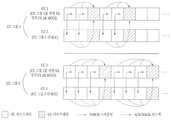
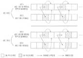
도 7 및 도 8은 본 발명의 실시예들을 예시한 것이다.
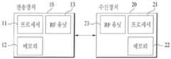
도 9는 본 발명을 수행하는 전송장치(10) 및 수신장치(20)의 구성요소를 나타내는 블록도이다.BRIEF DESCRIPTION OF THE DRAWINGS The accompanying drawings, which are included to provide a further understanding of the invention and are incorporated in and constitute a part of the specification, illustrate embodiments of the invention and, together with the description, serve to explain the principles of the invention.
1 shows an example of performing communication under a multi-carrier situation.
2 shows an example of a radio frame structure used in a wireless communication system.
3 illustrates an example of a downlink / uplink (DL / UL) slot structure in a wireless communication system.
4 illustrates a downlink subframe structure used in a 3GPP LTE (-A) system.
5 shows an example of an uplink subframe structure used in the 3GPP LTE (-A) system.
6 is a diagram for explaining the meaning of a cell of 3GPP LTE (-A).
Figures 7 and 8 illustrate embodiments of the present invention.
9 is a block diagram showing components of a transmitting
이하의 실시예들은 본 발명의 구성요소들과 특징들을 소정 형태로 결합한 것들이다. 각 구성요소 또는 특징은 별도의 명시적 언급이 없는 한 선택적인 것으로 고려될 수 있다. 각 구성요소 또는 특징은 다른 구성요소나 특징과 결합되지 않은 형태로 실시될 수 있다. 또한, 일부 구성요소들 및/또는 특징들을 결합하여 본 발명의 실시예를 구성할 수도 있다. 본 발명의 실시예들에서 설명되는 동작들의 순서는 변경될 수 있다. 어느 실시예의 일부 구성이나 특징은 다른 실시예에 포함될 수 있고, 또는 다른 실시예의 대응하는 구성 또는 특징과 교체될 수 있다.The following embodiments are a combination of elements and features of the present invention in a predetermined form. Each component or characteristic may be considered optional unless otherwise expressly stated. Each component or feature may be implemented in a form that is not combined with other components or features. In addition, some of the elements and / or features may be combined to form an embodiment of the present invention. The order of the operations described in the embodiments of the present invention may be changed. Some configurations or features of certain embodiments may be included in other embodiments, or may be replaced with corresponding configurations or features of other embodiments.
몇몇 경우, 본 발명의 개념이 모호해지는 것을 피하기 위하여 공지의 구조 및 장치는 생략되거나, 각 구조 및 장치의 핵심기능을 중심으로 한 블록도 형식으로 도시될 수 있다. 또한, 본 명세서 전체에서 동일한 구성요소에 대해서는 동일한 도면 부호를 사용하여 설명한다.In some instances, well-known structures and devices may be omitted or may be shown in block diagram form, centering on the core functionality of each structure and device, to avoid obscuring the concepts of the present invention. In the following description, the same components are denoted by the same reference numerals throughout the specification.
이하의 기술은 CDMA(Code Division Multiple Access), FDMA(Frequency Division Multiple Access), TDMA(Time Division Multiple Access), OFDMA(Orthogonal Frequency Division Multiple Access), SC-FDMA(Single Carrier Frequency Division Multiple Access) 등과 같은 다양한 무선 접속 시스템에 사용될 수 있다. CDMA는 UTRA(Universal Terrestrial Radio Access)나 CDMA2000과 같은 무선 기술(radio technology)로 구현될 수 있다. TDMA는 GSM(Global System for Mobile communications)/GPRS(General Packet Radio Service)/EDGE(Enhanced Data Rates for GSM Evolution)와 같은 무선 기술로 구현될 수 있다. OFDMA는 IEEE 802.11 (Wi-Fi), IEEE 802.16 (WiMAX), IEEE 802-20, E-UTRA(Evolved UTRA) 등과 같은 무선 기술로 구현될 수 있다. UTRA는 UMTS(Universal Mobile Telecommunications System)의 일부이다. 3GPP(3rd Generation Partnership Project) LTE(long term evolution)는 E-UTRA를 사용하는 E-UMTS(Evolved UMTS)의 일부로써, 하향링크에서 OFDMA를 채용하고 상향링크에서 SC-FDMA를 채용한다. LTE-A(Advanced)는 3GPP LTE의 진화이다. WiMAX는 IEEE 802.16e 규격(WirelessMAN-OFDMA Reference System) 및 발전된 IEEE 802.16m 규격(WirelessMAN-OFDMA Advanced system)에 의하여 설명될 수 있다. 명확성을 위하여 이하에서는 3GPP LTE(-A) 표준을 위주로 설명하지만 본 발명의 기술적 사상이 이에 제한되는 것은 아니다.The following description will be made on the assumption that the present invention is applicable to a CDMA system such as Code Division Multiple Access (CDMA), Frequency Division Multiple Access (FDMA), Time Division Multiple Access (TDMA), Orthogonal Frequency Division Multiple Access (OFDMA), and Single Carrier Frequency Division Multiple Access And can be used in various wireless access systems. CDMA may be implemented in radio technology such as Universal Terrestrial Radio Access (UTRA) or CDMA2000. The TDMA may be implemented in a wireless technology such as Global System for Mobile communications (GSM) / General Packet Radio Service (GPRS) / Enhanced Data Rates for GSM Evolution (EDGE). OFDMA may be implemented in wireless technologies such as IEEE 802.11 (Wi-Fi), IEEE 802.16 (WiMAX), IEEE 802-20, and Evolved UTRA (E-UTRA). UTRA is part of the Universal Mobile Telecommunications System (UMTS). 3GPP (3rd Generation Partnership Project) LTE (Long Term Evolution) is a part of E-UMTS (Evolved UMTS) using E-UTRA, adopting OFDMA in downlink and SC-FDMA in uplink. LTE-A (Advanced) is the evolution of 3GPP LTE. WiMAX can be described by the IEEE 802.16e standard (WirelessMAN-OFDMA Reference System) and the advanced IEEE 802.16m standard (WirelessMAN-OFDMA Advanced system). For clarity, the following description will focus on the 3GPP LTE (-A) standard, but the technical idea of the present invention is not limited thereto.
본 발명의 실시예들은 무선 접속 시스템들인 IEEE 802 시스템, 3GPP 시스템, 3GPP LTE 및 3GPP LTE-A(LTE-Advanced)시스템 및 3GPP2 시스템 중 적어도 하나에 개시된 표준 문서들에 의해 뒷받침될 수 있다. 즉, 본 발명의 실시예들 중 본 발명의 기술적 사상을 명확히 드러내기 위해 설명하지 않은 단계들 또는 부분들은 상기 문서들에 의해 뒷받침될 수 있다. 또한, 본 문서에서 개시하고 있는 모든 용어들은 상기 표준 문서에 의해 설명될 수 있다.Embodiments of the present invention may be supported by standard documents disclosed in at least one of IEEE 802 systems, 3GPP systems, 3GPP LTE and 3GPP LTE-Advanced (LTE-Advanced) systems and 3GPP2 systems, which are wireless access systems. That is, the steps or portions of the embodiments of the present invention that are not described in order to clearly illustrate the technical idea of the present invention can be supported by the documents. In addition, all terms disclosed in this document may be described by the standard document.
이하의 설명에서 사용되는 특정 용어들은 본 발명의 이해를 돕기 위해서 제공된 것이며, 이러한 특정 용어의 사용은 본 발명의 기술적 사상을 벗어나지 않는 범위에서 다른 형태로 변경될 수 있다.The specific terminology used in the following description is provided to aid understanding of the present invention, and the use of such specific terminology may be changed into other forms without departing from the technical idea of the present invention.
본 명세서에서 본 발명의 실시예들을 기지국(base station, BS)와 사용자기기(user equipment, UE) 간의 데이터 전송 및 수신의 관계를 중심으로 설명한다. 여기서, '기지국(BS)'은 UE와 직접적으로 통신을 수행하는 네트워크의 종단 노드(terminal node)로서의 의미를 갖는다. BS는 UE 및/또는 통신하여 각종 데이터 및 제어정보를 교환한다. 본 명세서에서 BS에 의해 수행되는 것으로 설명된 특정 동작은 경우에 따라서는 BS의 상위 노드(upper node)에 의해 수행될 수도 있다. 즉, BS를 포함하는 다수의 네트워크 노드들(network nodes)로 이루어지는 네트워크에서 UE와의 통신을 위해 수행되는 다양한 동작들은 BS 또는 BS 이외의 다른 네트워크 노드들에 의해 수행될 수 있음은 자명하다. '기지국(BS)'라는 용어는 고정국(fixed station), Node B, eNode B(eNB), 액세스 포인트(Access Point, AP) 등의 용어에 의해 대체될 수 있다. '사용자기기(UE)'는 고정되거나 이동성을 가질 수 있으며, BS와 통신하여 사용자 데이터 및/또는 각종 제어정보를 송수신하는 각종 기기들이 이에 속한다. 또한, '사용자기기(UE)'는 단말(Terminal), MS(Mobile Station), MSS(Mobile Subscriber Station), SS(Subscriber Station) 등의 용어로 대체될 수 있다.Embodiments of the present invention will be described herein with reference to the relationship between data transmission and reception between a base station (BS) and a user equipment (UE). Herein, 'base station (BS)' has a meaning as a terminal node of a network that directly communicates with a UE. The BS exchanges various data and control information by the UE and / or the communication. The particular operation described herein as being performed by the BS may be performed by an upper node of the BS, as the case may be. That is, it is apparent that various operations performed for communication with the UE in a network consisting of a plurality of network nodes including the BS can be performed by other network nodes other than the BS or the BS. The term 'base station (BS)' may be replaced by terms such as a fixed station, a Node B, an eNode B (eNB), an access point (AP) The 'UE' may be fixed or mobile, and various devices communicating with the BS to transmit and receive user data and / or various control information. The term 'user equipment UE' may be replaced with terminology such as a terminal, a mobile station (MS), a mobile subscriber station (MSS), and a subscriber station (SS).
본 발명에서 PDCCH(Physical Downlink Control CHannel)/PDSCH(Physical Downlink Shared CHannel)은 각각 DCI(Downlink Control Information)/하향링크 데이터를 나르는 시간-주파수 자원의 집합 혹은 자원요소의 집합을 의미한다. 또한, PUCCH(Physical Uplink Control CHannel)/PUSCH(Physical Uplink Shared CHannel)/PRACH(Physical Random Access CHannel)는 각각 UCI(Uplink Control Information)/상향링크 데이터/임의 접속 신호를 나르는 시간-주파수 자원의 집합 혹은 자원요소의 집합을 의미한다. 본 발명에서 사용자기기가 PUCCH/PUSCH/PRACH를 전송한다는 표현은, 각각, PUSCH/PUCCH/PRACH 상에서 상향링크 제어정보/상향링크 데이터/임의 접속 신호를 전송한다는 것과 동일한 의미로 사용된다. 또한, 본 발명에서 BS가 PDCCH/PDSCH를 전송한다는 표현은, 각각, PDCCH/PDSCH 상에서 하향링크 데이터/제어정보를 전송한다는 것과 동일한 의미로 사용된다.In the present invention, PDCCH (Physical Downlink Control Channel) / PDSCH (Physical Downlink Shared CHannel) refers to a set of time-frequency resources or a set of resource elements each carrying Downlink Control Information (DCI) / downlink data. The Physical Uplink Control Channel (PUCCH) / Physical Uplink Shared CHannel (PUSCH) / Physical Random Access Channel (PRACH) is a set of time-frequency resources for carrying Uplink Control Information (UCI) / uplink data / Means a set of resource elements. In the present invention, the expression that a user equipment transmits a PUCCH / PUSCH / PRACH is used in the same sense as to transmit uplink control information / uplink data / random access signal on a PUSCH / PUCCH / PRACH, respectively. Also, in the present invention, the expression that the BS transmits PDCCH / PDSCH is used in the same sense as to transmit downlink data / control information on the PDCCH / PDSCH, respectively.
도 2는 무선 통신 시스템에서 사용되는 무선 프레임 구조의 일 예를 나타낸 것이다. 특히, 도 2(a)는 3GPP LTE(-A)에서 FDD에 사용될 수 있는 무선 프레임 구조를 예시한 것이고, 도 2(b)는 3GPP LTE(-A)에서 TDD에 사용될 수 있는 무선 프레임 구조를 예시한 것이다.2 shows an example of a radio frame structure used in a wireless communication system. Particularly, FIG. 2A illustrates a radio frame structure that can be used for FDD in 3GPP LTE (-A), FIG. 2B illustrates a radio frame structure that can be used for TDD in 3GPP LTE (-A) .
도 2를 참조하면, 3GPP LTE(-A)에서 사용되는 무선프레임은 10ms(307200Ts)의 길이를 가지며, 10개의 균등한 크기의 서브프레임으로 구성된다. 일 무선프레임 내 10개의 서브프레임에는 각각 번호가 부여될 수 있다. 여기에서, Ts는 샘플링 시간을 나타내고, Ts=1/(2048*15kHz)로 표시된다. 각각의 서브프레임은 1ms의 길이를 가지며 2개의 슬롯으로 구성된다. 일 무선프레임 내에서 20개의 슬롯들은 0부터 19까지 순차적으로 넘버링될 수 있다. 각각의 슬롯은 0.5ms의 길이를 가진다. 일 서브프레임을 전송하기 위한 시간은 전송시간간격(TTI: transmission time interval)로 정의된다. 시간 자원은 무선프레임 번호(혹은 무선 프레임 인덱스라고도 함)와 서브프레임 번호(혹은 서브프레임 번호라고도 함), 슬롯 번호(혹은 슬롯 인덱스) 등에 의해 구분될 수 있다.2, the radio frame used in the 3GPP LTE (-A) has a length of 10ms (307200Ts), it is composed of 10 sub-frames of equal size. 10 subframes within one radio frame may be assigned respective numbers. Here, Ts denotes the sampling time, and Ts = 1 / (2048 * 15 kHz). Each subframe is 1 ms long and consists of two slots. 20 slots in one radio frame can be sequentially numbered from 0 to 19. [ Each slot has a length of 0.5 ms. The time for transmitting one subframe is defined as a transmission time interval (TTI). The time resource may be classified by a radio frame number (or a radio frame index), a subframe number (also referred to as a subframe number), a slot number (or a slot index), and the like.
무선 프레임은 듀플렉스(duplex) 모드에 따라 다르게 설정(configure)될 수 있다. 예를 들어, FDD 모드에서, 하향링크(DL) 전송 및 상향링크(UL) 전송은 주파수에 의해 구분되므로, 무선 프레임은 소정 반송파 주파수에서 동작하는 소정 주파수 대역에 대해 DL 서브프레임 또는 UL 서브프레임 중 하나만을 포함한다. TDD 모드에서 DL 전송 및 UL 전송은 시간에 의해 구분되므로, 소정 반송파 주파수에서 동작하는 소정 주파수 대역에 대해 무선 프레임은 하향링크 서브프레임과 UL 서브프레임을 모두 포함한다.The radio frame may be configured differently according to the duplex mode. For example, in the FDD mode, since the downlink (DL) transmission and the uplink (UL) transmission are divided by frequency, the radio frame is a DL subframe or a UL subframe for a predetermined frequency band operating at a predetermined carrier frequency Only one. Since the DL transmission and the UL transmission in the TDD mode are divided by time, the radio frame includes both the DL subframe and the UL subframe for a predetermined frequency band operating at a predetermined carrier frequency.
표 1은 TDD 모드에서, 무선 프레임 내 서브프레임들의 DL-UL 설정(configuration)을 예시한 것이다.Table 1 illustrates the DL-UL configuration of subframes in a radio frame in TDD mode.

표 1에서, D는 하향링크 서브프레임을, U는 UL 서브프레임을, S는 특이(special) 서브프레임을 나타낸다. 특이 서브프레임은 DwPTS(Downlink Pilot TimeSlot), GP(Guard Period), UpPTS(Uplink Pilot TimeSlot)의 3개 필드를 포함한다. DwPTS는 DL 전송용으로 유보되는 시간 구간이며, UpPTS는 UL 전송용으로 유보되는 시간 구간이다. 표 2는 특이 프레임의 설정을 예시한 것이다.In Table 1, D denotes a downlink subframe, U denotes an UL subframe, and S denotes a special subframe. The specific subframe includes three fields of Downlink Pilot Time Slot (DwPTS), Guard Period (GP), and UpPTS (Uplink Pilot Time Slot). DwPTS is a time interval reserved for DL transmission, and UpPTS is a time interval reserved for UL transmission. Table 2 shows the setting of a singular frame.

도 3은 무선 통신 시스템에서 하향링크/상향링크(DL/UL) 슬롯 구조의 일례를 나타낸 것이다. 특히, 도 3은 3GPP LTE(-A) 시스템의 자원격자(resource grid)의 구조를 나타낸다. 안테나 포트당 1개의 자원격자가 있다.3 illustrates an example of a downlink / uplink (DL / UL) slot structure in a wireless communication system. In particular, Figure 3 shows the structure of the resource grid of the 3GPP LTE (-A) system. There is one resource grid per antenna port.
도 3을 참조하면, 슬롯은 시간 도메인에서 복수의 OFDM(Orthogonal Frequency Division Multiplexing) 심볼을 포함하고, 주파수 도메인에서 다수의 자원블록(resource block, RB)을 포함한다. OFDM 심볼은 일 심볼 구간을 의미하기도 한다. 도 3을 참조하면, 각 슬롯에서 전송되는 신호는 NDL/ULRB*NRBsc개의 부반송파(subcarrier)와 NDL/ULsymb개의 OFDM 심볼로 구성되는 자원격자(resource grid)로 표현될 수 있다. 여기서, NDLRB은 하향링크 슬롯에서의 자원블록(resource block, RB)의 개수를 나타내고, NULRB은 UL 슬롯에서의 RB의 개수를 나타낸다. NDLRB와 NULRB은 DL 전송 대역폭과 UL 전송 대역폭에 각각 의존한다. NDLsymb은 하향링크 슬롯 내 OFDM 심볼의 개수를 나타내며, NULsymb은 UL 슬롯 내 OFDM 심볼의 개수를 나타낸다. NRBsc는 하나의 RB를 구성하는 부반송파의 개수를 나타낸다.Referring to FIG. 3, a slot includes a plurality of Orthogonal Frequency Division Multiplexing (OFDM) symbols in the time domain and a plurality of resource blocks (RBs) in the frequency domain. The OFDM symbol also means one symbol period. Referring to FIG. 3, a signal transmitted in each slot may be expressed as a resource grid consisting of NDL/ULRB * NRBsc sub-carriers and NDL/ULsymb OFDM symbols . Here, NDLRB represents the number of resource blocks (RBs) in the downlink slot, and NULRB represents the number ofRBs in the UL slot. NDLRB and NULRB depend on the DL transmission bandwidth and the UL transmission bandwidth, respectively. NDLsymb denotes the number of OFDM symbols in the downlink slot, and NULsymb denotes the number of OFDM symbols in the UL slot. NRBsc represents the number of sub-carriers constituting one RB.
OFDM 심볼은 다중 접속 방식에 따라 OFDM 심볼, SC-FDM 심볼 등으로 불릴 수 있다. 하나의 슬롯에 포함되는 OFDM 심볼의 수는 채널 대역폭, CP의 길이에 따라 다양하게 변경될 수 있다. 예를 들어, 표준(normal) CP의 경우에는 하나의 슬롯이 7개의 OFDM 심볼을 포함하나, 확장(extended) CP의 경우에는 하나의 슬롯이 6개의 OFDM 심볼을 포함한다. 도 3에서는 설명의 편의를 위하여 하나의 슬롯이 7 OFDM 심볼로 구성되는 서브프레임을 예시하였으나, 본 발명의 실시예들은 다른 개수의 OFDM 심볼을 갖는 서브프레임들에도 마찬가지의 방식으로 적용될 수 있다. 도 3을 참조하면, 각 OFDM 심볼은, 주파수 도메인에서, NDL/ULRB*NRBsc개의 부반송파를 포함한다. 부반송파의 유형은 데이터 전송을 위한 데이터 부반송파, 참조신호의 전송 위한 참조신호 부반송파, 가드 밴드(guard band) 및 DC 성분을 위한 널 부반송파로 나뉠 수 있다. DC 성분을 위한 널 부반송파는 미사용인 채 남겨지는 부반송파로서, OFDM 신호 생성 과정 혹은 주파수 상향변환 과정에서 반송파 주파수(carrier freqeuncy, f0)로 맵핑된다. 반송파 주파수는 중심 주파수(center frequency)라고도 한다.The OFDM symbol may be referred to as an OFDM symbol, an SC-FDM symbol, or the like according to a multiple access scheme. The number of OFDM symbols included in one slot may be variously changed according to the channel bandwidth and the length of the CP. For example, one slot includes seven OFDM symbols in the case of a normal CP, and one slot includes six OFDM symbols in the case of an extended CP. In FIG. 3, a subframe in which one slot is composed of seven OFDM symbols is illustrated for convenience of description. However, the embodiments of the present invention can be applied to subframes having a different number of OFDM symbols in a similar manner. Referring to FIG. 3, each OFDM symbol includes NDL/ULRB * NRBsc subcarriers in the frequency domain. The types of subcarriers can be divided into data subcarriers for data transmission, reference signal subcarriers for transmission of reference signals, guard bands, and null subcarriers for DC components. The null subcarrier for the DC component is a subcarrier that is left unused and is mapped to the carrier frequency (f0 ) in the OFDM signal generation process or the frequency up-conversion process. The carrier frequency is also referred to as the center frequency.
일 RB는 시간 도메인에서 NDL/ULsymb개(예를 들어, 7개)의 연속하는 OFDM 심볼로서 정의되며, 주파수 도메인에서 NRBsc개(예를 들어, 12개)의 연속하는 부반송파에 의해 정의된다. 참고로, 하나의 OFDM 심볼과 하나의 부반송파로 구성된 자원을 자원요소(resource element, RE) 혹은 톤(tone)이라고 한다. 따라서, 하나의 RB는 NDL/ULsymb*NRBsc개의 자원요소로 구성된다. 자원격자 내 각 자원요소는 일 슬롯 내 인덱스 쌍 (k, 1)에 의해 고유하게 정의될 수 있다. k는 주파수 도메인에서 0부터 NDL/ULRB*NRBsc-1까지 부여되는 인덱스이며, l은 시간 도메인에서 0부터 NDL/ULsymb-1까지 부여되는 인덱스이다.One RB is defined as NDL/ULsymb consecutive OFDM symbols in the time domain (e.g., 7) and is represented by NRBsc (e.g., twelve) consecutive subcarriers in the frequency domain Is defined. For reference, a resource composed of one OFDM symbol and one subcarrier is referred to as a resource element (RE) or a tone. Therefore, one RB consists of NDL / ULsymb * NRBsc resource elements. Each resource element in the resource grid can be uniquely defined by an index pair (k, 1) in one slot. k is an index assigned from 0 to NDL / ULRB * NRBsc -1 in the frequency domain, and 1 is an index assigned from 0 to NDL/ULsymb -1 in the time domain.
일 서브프레임에서 NRBsc개의 연속하는 동일한 부반송파를 점유하면서, 상기 서브프레임의 2개의 슬롯 각각에 1개씩 위치하는 2개의 RB를 물리자원블록(physical resource block, PRB) 쌍이라고 한다. PRB 쌍을 구성하는 2개의 RB는 동일한 PRB 번호(혹은, PRB 인덱스라고도 함)를 갖는다.Two RBs, one in each of two slots of the subframe occupying NRBsc consecutive identical subcarriers in one subframe, are referred to as a pair of physical resource blocks (PRB). The two RBs constituting the PRB pair have the same PRB number (or PRB index).
도 4는 3GPP LTE(-A) 시스템에서 사용되는 하향링크 서브프레임 구조를 예시한 것이다.4 illustrates a downlink subframe structure used in a 3GPP LTE (-A) system.
도 4를 참조하면, DL 서브프레임은 시간 도메인에서 제어영역과 데이터영역으로 구분된다. 도 4를 참조하면, 서브프레임의 첫 번째 슬롯에서 앞부분에 위치한 최대 3(혹은 4)개의 OFDM 심볼은 제어 채널이 할당되는 제어영역(control region)에 대응한다. 이하, DL 서브프레임에서 PDCCH 전송에 이용가능한 자원영역을 PDCCH 영역이라 칭한다. 제어영역으로 사용되는 OFDM 심볼(들)이 아닌 남은 OFDM 심볼들은 PDSCH(Physical Downlink Shared CHancel)가 할당되는 데이터영역(data region)에 해당한다. 이하, DL 서브프레임에서 PDSCH 전송에 이용가능한 자원영역을 PDSCH 영역이라 칭한다. 3GPP LTE에서 사용되는 DL 제어 채널의 예는 PCFICH(Physical Control Format Indicator Channel), PDCCH(Physical Downlink Control Channel), PHICH(Physical hybrid ARQ indicator Channel) 등을 포함한다. PCFICH는 서브프레임의 첫 번째 OFDM 심볼에서 전송되고 서브프레임 내에서 제어 채널의 전송에 사용되는 OFDM 심볼의 개수에 관한 정보를 나른다. PHICH는 UL 전송에 대한 응답으로 HARQ(Hybrid Automatic Repeat Request) ACK/NACK(acknowledgment/negative-acknowledgment) 신호를 나른다.Referring to FIG. 4, a DL subframe is divided into a control region and a data region in the time domain. Referring to FIG. 4, a maximum of 3 (or 4) OFDM symbols located at the beginning of a first slot of a subframe corresponds to a control region to which a control channel is allocated. Hereinafter, a resource region available for PDCCH transmission in a DL subframe is referred to as a PDCCH region. The remaining OFDM symbols other than the OFDM symbol (s) used as a control region correspond to a data region to which PDSCH (Physical Downlink Shared CHancel) is allocated. Hereinafter, a resource region usable for PDSCH transmission in a DL subframe is referred to as a PDSCH region. Examples of the DL control channel used in the 3GPP LTE include a physical control format indicator channel (PCFICH), a physical downlink control channel (PDCCH), a physical hybrid ARQ indicator channel (PHICH), and the like. The PCFICH carries information about the number of OFDM symbols transmitted in the first OFDM symbol of the subframe and used for transmission of the control channel in the subframe. The PHICH carries an HARQ (Hybrid Automatic Repeat Request) ACK / NACK (acknowledgment / negative-acknowledgment) signal in response to the UL transmission.
PDCCH를 통해 전송되는 제어 정보를 DCI(Downlink Control Information)라고 지칭한다. DCI는 UE 또는 UE 그룹을 위한 자원 할당 정보 및 다른 제어 정보를 포함한다. 예를 들어, DCI는 DL 공유 채널(downlink shared channel, DL-SCH)의 전송 포맷 및 자원 할당 정보(이하, DL 그랜트), UL 공유 채널(uplink shared channel, UL-SCH)의 전송 포맷 및 자원 할당 정보(이하, UL 그랜트), 페이징 채널(paging channel, PCH) 상의 페이징 정보, DL-SCH 상의 시스템 정보, PDSCH 상에서 전송되는 임의 접속 응답과 같은 상위-계층 제어 메시지의 자원 할당 정보, UE 그룹 내의 개별 UE들에 대한 Tx 파워 제어 명령 세트, Tx 파워 제어 명령, VoIP(Voice over IP)의 활성화 지시 정보, DAI(downlink assignment index) 등을 포함한다. PDCCH는 하나 또는 복수의 연속된 제어 채널 요소(control channel element, CCE)들의 집성(aggregation) 상에서 전송된다. CCE는 PDCCH에 무선 채널 상태에 기초한 부호화율(coding rate)를 제공하기 위해 사용되는 논리적 할당 유닛이다. CCE는 복수의 자원 요소 그룹(resource element group, REG)에 대응한다. 예를 들어, 하나의 CCE는 9개의 REG에 대응되고 하나의 REG는 4개의 RE에 대응한다.The control information transmitted through the PDCCH is referred to as DCI (Downlink Control Information). The DCI includes resource allocation information and other control information for the UE or UE group. For example, the DCI may include a transport format of a DL shared channel (DL-SCH), a resource allocation information (DL grant), a transport format of an uplink shared channel (UL-SCH) Resource allocation information of a higher-layer control message such as information (hereinafter referred to as UL grant), paging information on a paging channel (PCH), system information on DL-SCH, random access response transmitted on PDSCH, A Tx power control command set for UEs, a Tx power control command, activation indication information of VoIP (Voice over IP), a downlink assignment index (DAI), and the like. The PDCCH is transmitted on an aggregation of one or more contiguous control channel elements (CCEs). The CCE is a logical allocation unit used for providing a PDCCH with a coding rate based on a radio channel condition. The CCE corresponds to a plurality of resource element groups (REG). For example, one CCE corresponds to nine REGs, and one REG corresponds to four REs.
BS는 데이터영역을 통해 UE 혹은 UE 그룹을 위한 데이터를 전송할 수 있다. 상기 데이터영역을 통해 전송되는 데이터를 사용자데이터라 칭하기도 한다. 사용자데이터의 전송을 위해, 데이터영역에는 PDSCH(Physical Downlink Shared CHannel)가 할당될 수 있다. PCH(Paging channel) 및 DL-SCH(Downlink-shared channel)는 PDSCH를 통해 전송된다. UE는 PDCCH를 통해 전송되는 제어정보를 복호하여 PDSCH를 통해 전송되는 데이터를 읽을 수 있다. 일 PDCCH가 나르는 DCI는 DCI 포맷에 따라서 그 크기와 용도가 다르며, 부호화율에 따라 그 크기가 달라질 수 있다. PDSCH의 데이터가 어떤 UE 혹은 UE 그룹에게 전송되는지, 상기 UE 혹은 UE 그룹이 어떻게 PDSCH 데이터를 수신하고 복호해야 하는지 등을 나타내는 정보가 PDCCH에 포함되어 전송된다. 예를 들어, 특정 PDCCH가 "A"라는 RNTI(Radio Network Temporary Identity)로 CRC 마스킹(masking)되어 있고, "B"라는 무선자원(예, 주파수 위치) 및 "C"라는 전송형식정보(예, 전송 블록 사이즈, 변조 방식, 코딩 정보 등)를 이용해 전송되는 데이터에 관한 정보가 특정 DL 서브프레임을 통해 전송된다고 가정한다. UE는 자신이 가지고 있는 RNTI 정보를 이용하여 PDCCH를 모니터링하고, "A"라는 RNTI를 가지고 있는 UE는 PDCCH를 수신하고, 수신한 PDCCH의 정보를 통해 "B"와 "C"에 의해 지시되는 PDSCH를 수신한다.The BS may transmit data for the UE or UE group through the data area. Data transmitted through the data area is also referred to as user data. For transmission of user data, a PDSCH (Physical Downlink Shared CHannel) may be allocated to the data area. A paging channel (PCH) and a downlink-shared channel (DL-SCH) are transmitted through the PDSCH. The UE may decode the control information transmitted through the PDCCH and read the data transmitted through the PDSCH. The DCI carried by one PDCCH differs in size and usage according to the DCI format, and its size may vary according to the coding rate. Information indicating to which UE or UE group the data of the PDSCH is transmitted, how the UE or UE group should receive and decode the PDSCH data, and the like are included in the PDCCH and transmitted. For example, if a particular PDCCH is CRC masked with an RNTI (Radio Network Temporary Identity) of "A ", transmission format information (e.g., frequency position) Transmission block size, modulation scheme, coding information, and the like) is transmitted through a specific DL sub-frame. The UE monitors the PDCCH using the RNTI information it owns, and the UE having the RNTI of "A " receives the PDCCH and transmits the PDSCH indicated by" B " .
복수의 PDCCH가 제어영역에서 전송될 수 있다. UE는 상기 복수의 PDCCH를 모니터하여, 자신의 PDCCH를 검출할 수 있다. 기본적으로 UE는 자신의 PDCCH가 전송되는 위치를 모르기 때문에, 매 서브프레임마다 해당 DCI 포맷의 모든 PDCCH를 자신의 식별자를 가진 PDCCH를 수신할 때까지 블라인드 검출(블라인드 복호(decoding)이라고도 함)을 수행한다.A plurality of PDCCHs may be transmitted in the control domain. The UE can monitor the plurality of PDCCHs and detect its PDCCH. Basically, since the UE does not know the location where its PDCCH is transmitted, blind detection (also called blind decoding) is performed until all PDCCHs of the corresponding DCI format are received in each subframe until the PDCCH having its own identifier is received do.
도 5는 3GPP LTE(-A) 시스템에서 사용되는 상향링크 서브프레임 구조의 일례를 나타낸 것이다.5 shows an example of an uplink subframe structure used in the 3GPP LTE (-A) system.
도 5를 참조하면, UL 서브프레임은 주파수 도메인에서 제어영역과 데이터영역으로 구분될 수 있다. 하나 또는 여러 PUCCH(physical uplink control channel)가 UCI(uplink control information)를 나르기 위해, 상기 제어영역에 할당될 수 있다. 하나 또는 여러 PUSCH(physical uplink shared channel)가 사용자 데이터를 나르기 위해, UL 서브프레임의 데이터영역에 할당될 수 있다. UL 서브프레임 내 제어영역과 데이터영역은 PUCCH 영역과 PUSCH 영역으로 각각 불리기도 한다. 상기 데이터영역에는 사운딩 참조신호(sounding reference signal, SRS)가 할당될 수도 있다. SRS는 시간 도메인에서는 UL 서브프레임의 가장 마지막에 위치하는 OFDM 심볼, 주파수 도메인에서는 상기 UL 서브프레임의 데이터 전송 대역, 즉, 데이터영역 상에서 전송된다. 동일한 서브프레임의 마지막 OFDM 심볼에서 전송/수신되는 여러 UE들의 SRS들은 주파수 위치/시퀀스에 따라 구분이 가능하다.Referring to FIG. 5, the UL subframe may be divided into a control domain and a data domain in the frequency domain. One or several physical uplink control channels (PUCCHs) may be assigned to the control region to carry UCI (uplink control information). One or several physical uplink shared channels (PUSCHs) may be allocated to the data area of the UL subframe to carry user data. The control area and the data area in the UL subframe are also referred to as a PUCCH area and a PUSCH area, respectively. A sounding reference signal (SRS) may be allocated to the data area. The SRS is transmitted on the last OFDM symbol in the UL subframe in the time domain and on the data transmission band, i.e., the data area, in the UL subframe in the frequency domain. SRSs of UEs transmitted / received in the last OFDM symbol of the same subframe can be classified according to the frequency location / sequence.
UE가 UL 전송에 SC-FDMA 방식을 채택하는 경우, 단일 반송파 특성을 유지하기 위해, 3GPP LTE 릴리즈(release) 8 혹은 릴리즈 9 시스템에서는, 일 반송파 상에서는 PUCCH와 PUSCH를 동시에 전송할 수 없다. 3GPP LTE 릴리즈 10 시스템에서는, PUCCH와 PUSCH의 동시 전송 지원 여부가 상위 계층에서 지시될 수 있다.When the UE adopts the SC-FDMA scheme for the UL transmission, in the 3GPP LTE Release 8 or Release 9 system, the PUCCH and the PUSCH can not be simultaneously transmitted on a single carrier in order to maintain the single carrier characteristic. In the
UL 서브프레임에서는 DC(Direct Current) 부반송파를 기준으로 거리가 먼 부반송파들이 제어영역으로 활용된다. 다시 말해, UL 전송 대역폭의 양쪽 끝부분에 위치하는 부반송파들이 하향링크 데이터에 대한 ACK/NACK, 하향링크에 대한 채널상태정보(예를 들어, 채널품질지시자(Channel Quality Indicator, CQI), 프리코딩행렬지시자(Precoding Matrix Index, PMI), 랭크지시자(Rank Indicator, RI) 등), 스케줄링요청(scheduling request, SR) 등과 같은 상향링크 제어정보의 전송에 할당된다. DC 부반송파는 신호 전송에 사용되지 않고 남겨지는 성분으로, 주파수 상향변환 과정에서 반송파 주파수 f0로 맵핑된다. 일 UE에 대한 PUCCH는 일 서브프레임에서, 일 반송파 주파수에서 동작하는 자원들에 속한 RB 쌍에 할당되며, 상기 RB 쌍에 속한 RB들은 두 개의 슬롯에서 각각 다른 부반송파를 점유한다. 이와 같이 할당되는 PUCCH를, PUCCH에 할당된 RB 쌍이 슬롯 경계에서 주파수 호핑된다고 표현한다. 다만, 주파수 호핑이 적용되지 않는 경우에는, RB 쌍이 동일한 부반송파를 점유한다.In the UL subframe, subcarriers far away from the direct current (DC) subcarrier are used as a control region. In other words, the subcarriers located at both ends of the UL transmission bandwidth transmit ACK / NACK for downlink data, channel state information for downlink (e.g., a channel quality indicator (CQI), a precoding matrix Such as a scheduling request (SR), a precoding matrix index (PMI), a rank indicator (RI), etc.). The DC subcarrier is a component that is left unused for signal transmission and is mapped to the carrier frequency f0 in the frequency up conversion process. In one subframe, a PUCCH for one UE is allocated to an RB pair belonging to resources operating at a single carrier frequency, and RBs belonging to the RB pair occupy different subcarriers in two slots. The PUCCH allocated as described above is expressed as the RB pair allocated to the PUCCH is frequency-hopped at the slot boundary. However, when frequency hopping is not applied, the RB pairs occupy the same subcarrier.
일 PUCCH가 나르는 UCI는 PUCCH 포맷에 따라서 그 크기와 용도가 다르며, 부호화율에 따라 그 크기가 달라질 수 있다. UE는 상위(higher) 레이어 신호 혹은 동적 제어 신호에 의한 명시적(explicit) 방식, 혹은 암묵적(implicit) 방식에 의해 BS로부터 UCI의 전송을 위한 PUCCH 자원을 할당 받는다. PUCCH를 위해 사용되는 물리자원들은 상위 계층에 의해 주어지는 2개의 파라미터, N(2)RB 및 N(1)cs에 의존한다. 변수 N(2)RB≥0은 각 슬롯에서 PUCCH 포맷 2/2a/2b 전송에 이용가능한 대역폭을 나타내며, NRBsc개의 정수배로 표현된다. 변수 N(1)cs는 포맷 1/1a/1b 및 2/2a/2b의 혼합을 위해 사용되는 자원블록에서 PUCCH 포맷 1/1a/1b를 위해 사용된 순환쉬프트의 개수를 나타낸다. N(1)cs의 값은 {0, 1,..., 7}의 범위 내에서 △PUCCHshift의 정수배가 된다. △PUCCHshift는 상위 계층에 의해 제공된다. N(1)cs=0이면 혼합된 자원블록이 없게 되며, 각 슬롯에서 많아야 1개 자원블록이 포맷 1/1a/1b 및 2/2a/2b의 혼합을 지원한다. 안테나 포트 p에 의해 PUCCH 포맷 1/1a/1b, 2/2a/2b 및 3의 전송을 위해 사용되는 자원들은 음이 아닌 정수 인덱스인 n(1,p)PUCCH, n(2,p)PUCCH < N(2)RBNRBsc + ceil(N(1)cs/8)·(NRBsc - N(1)cs - 2) 및 n(2,p)PUCCH에 의해 각각 표현된다. 구체적으로, PUCCH 포맷별로 기정의된 특정 규칙에 따라, PUCCH 자원 인덱스로부터 해당 UCI에 적용될 직교시퀀스 및/또는 순환쉬프트가 결정되며 PUCCH가 맵핑될, 서브프레임 내 2개 자원블록들의 자원 인덱스들이 주어진다.A UCI carried by one PUCCH differs in size and usage according to the PUCCH format, and its size may vary according to the coding rate. The UE is allocated a PUCCH resource for transmission of the UCI from the BS by an explicit method or an implicit method by a higher layer signal or a dynamic control signal. The physical resources used for PUCCH depend on the two parameters given by the upper layer, N(2)RB and N(1)cs . Variable N(2)RB ≥ 0 represents the bandwidth available for
예를 들어, PDCCH 혹은 상기 PDCCH와 연관된 PDSCH에 대한 ACK/NACK 정보의 전송에 사용되는 PUCCH 포맷 1a/1b용 자원은 암묵적으로 할당된다. PUCCH 포맷 1a/1b를 위한 PUCCH 자원의 인덱스는 PDCCH 전송에 사용되는 CCE들의 인덱스들 중 특정 CCE 인덱스(예를 들어, 최저 CCE 인덱스, nCCE)에 링크되어 결정된다. 예를 들어, 3GPP LTE(-A) 시스템에서 2개 안테나 포트(p0 및 p1)에 의한 전송을 위한 PUCCH 포맷 1a/1b 자원의 인덱스는 다음과 같이 정해진다.For example, resources for the PUCCH format 1a / 1b used for transmission of the ACK / NACK information for the PDCCH or the PDSCH associated with the PDCCH are implicitly allocated. The index of the PUCCH resource for the PUCCH format 1a / 1b is determined by linking to a specific CCE index (e.g., the lowest CCE index, nCCE ) among the indexes of the CCEs used for the PDCCH transmission. For example, the index of the PUCCH format 1a / 1b resource for transmission by the two antenna ports (p0 and p1 ) in the 3GPP LTE (-A) system is determined as follows.


여기서, n(1,p=p0)PUCCH는 안테나 포트 p0가 사용할 PUCCH 자원의 인덱스(즉, 번호)를 나타내고, n(1,p=p1)PUCCH는 안테나 포트 p1이 사용할 PUCCH 자원 인덱스를 나타내며, N(1)PUCCH는 상위 계층으로부터 전달받는 시그널링 값을 나타낸다. nCCE는 PDCCH 전송에 사용된 CCE 인덱스들 중에서 가장 작은 값에 해당한다.Here, n(1, p =p0)PUCCH denotes the index of a PUCCH resource, the antenna port p0 used (i.e., number), n(1, p =p1)PUCCH is a PUCCH resource index is an antenna port p1 using And N(1)PUCCH denotes a signaling value received from an upper layer. nCCE corresponds to the smallest value among CCE indexes used for PDCCH transmission.
한편, 도 1에서 언급한 바와 같이, 최근 반송파 집성(carrier aggregation 또는 bandwidth aggregation) 기술이 논의되고 있다. 예를 들어, 도 1을 참조하면, 상/하향링크에 각각 5개의 20MHz 컴포넌트 반송파(component carrier, CC)들이 모여서 100MHz의 대역폭이 지원될 수 있다. 각각의 CC들은 주파수 도메인에서 서로 인접하거나 비-인접할 수 있다. 이로 제한되는 것은 아니지만, 표 3의 E-UTRA(Evolved Universal Terrestrial Radio Access) 동작 대역이 반송파 집성에 사용될 수 있다.Meanwhile, as mentioned in FIG. 1, a carrier aggregation or bandwidth aggregation technique is being discussed. For example, referring to FIG. 1, five 20 MHz component carriers (CCs) may be aggregated on the uplink and downlink, respectively, to support a bandwidth of 100 MHz. Each CC may be adjacent or non-adjacent to one another in the frequency domain. Although not limited to this, the Evolved Universal Terrestrial Radio Access (E-UTRA) operating band of Table 3 may be used for carrier aggregation.

도 1은 편의상 UL CC의 대역폭과 DL CC의 대역폭이 모두 동일하고 대칭인 경우가 도시되었으나, 각 CC의 대역폭은 독립적으로 정해질 수 있다. 또한, UL CC의 개수와 DL CC의 개수가 다른 비대칭적 반송파 집성도 가능하다. 여기서, UL CC와 DL CC는 각각 UL 자원들(UL resources)와 DL 자원들(DL resources)라고 불리기도 한다. BS가 X개의 DL CC를 관리하더라도, 특정 UE가 수신할 수 있는 주파수 대역은 Y(≤X)개의 DL CC로 한정될 수 있다. 이 경우, UE는 상기 Y개의 CC를 통해 전송되는 DL 신호/데이터를 모니터하면 된다. 또한, BS가 L개의 UL CC를 관리하더라도, 특정 UE가 송신할 수 있는 주파수 대역은 M(≤L)개의 UL CC로 한정될 수 있다. 이와 같이 특정 UE에게 한정된 DL/UL CC를 특정 UE에서의 설정된(configured) 서빙 (serving) UL/DL CC라고 부를 수 있다. BS는 상기 BS가 관리하는 CC들 중 일부 또는 전부를 활성화(activate)하거나, 일부 CC를 비활성화(deactivate)함으로써, 상기 UE에게 소정 개수의 CC를 할당할 수 있다. 상기 BS는 활성화/비활성화되는 CC를 변경할 수 있으며, 활성화/비활성화되는 CC의 개수를 변경할 수 있다. 반송파 집성에 대한 다양한 파라미터는 셀-특정적(cell-specific), UE 그룹-특정적(UE group-specific) 또는 UE-특정적(UE-specific)으로 설정(configure)될 수 있다. BS가 UE에 이용가능한 CC를 셀-특정적 혹은 UE-특정적으로 할당하면, 상기 UE에 대한 CC 할당이 전면적으로 재설정되거나 상기 UE가 핸드오버(handover)되지 않는 한, 일단 할당된 CC 중 적어도 하나는 비활성화되지 않는다. 이하에서는, UE에 대한 CC 할당의 전면적인 재구성이 아닌 한 비활성화되지 않는 CC를 PCC(Primary CC)라고 칭하고, BS가 자유롭게 활성화/비활성화할 수 있는 CC를 SCC(Secondary CC)라고 칭한다. 단일 반송파 통신은 1개의 PCC를 UE와 BS 사이의 통신에 이용하며, SCC는 통신에 이용하지 않는다.FIG. 1 shows a case in which the bandwidth of the UL CC and the bandwidth of the DL CC are both the same and symmetric, but the bandwidth of each CC can be determined independently. Asymmetric carrier aggregation with different numbers of UL CCs and DL CCs is also possible. Herein, the UL CC and the DL CC are also referred to as UL resources and DL resources, respectively. Even if the BS manages X DL CCs, the frequency band that a specific UE can receive is limited to Y (? X) DL CCs. In this case, the UE monitors DL signals / data transmitted through the Y CCs. Also, even if the BS manages L UL CCs, the frequency band that a specific UE can transmit may be limited to M (L) UL CCs. Thus, a DL / UL CC defined for a particular UE may be referred to as a configured serving UL / DL CC at a particular UE. The BS can allocate a predetermined number of CCs to the UE by activating some or all CCs managed by the BS or deactivating some CCs. The BS may change the CC to be activated / deactivated, and may change the number of CCs to be activated / deactivated. The various parameters for carrier aggregation may be configured to be cell-specific, UE group-specific or UE-specific. If the BS allocates a CC available for the UE in a cell-specific or UE-specific manner, at least one of the CCs allocated once the UE has been entirely re-established or the UE is not handed over One is not disabled. Hereinafter, a CC that is not deactivated is referred to as PCC (Primary CC), and a CC that can be freely activated / deactivated by the BS is referred to as an SCC (Secondary CC), unless it is a full reconfiguration of the CC allocation for the UE. Single carrier communication uses one PCC for communication between UE and BS, and SCC does not use for communication.
한편, 3GPP LTE(-A)는 무선 자원을 관리하기 위해 셀(Cell)의 개념을 사용한다. 도 6은 3GPP LTE(-A)의 셀(Cell)의 의미를 설명하기 위한 도면이다.Meanwhile, 3GPP LTE (-A) uses the concept of a cell to manage radio resources. 6 is a diagram for explaining the meaning of a cell of 3GPP LTE (-A).
셀이라 함은 하향링크 자원(DL resources)와 상향링크 자원(UL resources)의 조합, 즉, DL CC와 UL CC의 조합으로 정의된다. 셀은 DL 자원 단독, 또는 DL 자원과 UL 자원의 조합으로 구성될 수 있다. 반송파 집성이 지원되는 경우, DL 자원(또는, DL CC)의 반송파 주파수(carrier frequency)와 UL 자원(또는, UL CC)의 반송파 주파수(carrier frequency) 사이의 링키지(linkage)는 시스템 정보에 의해 지시될 수 있다. 예를 들어, 시스템 정보 블록 타입2(System Information Block Type2, SIB2) 링키지(linkage)에 의해서 DL 자원과 UL 자원의 조합이 지시될 수 있다.A cell is defined as a combination of DL resources and UL resources, that is, a combination of DL CC and UL CC. A cell may consist of DL resources alone, or a combination of DL resources and UL resources. If carrier aggregation is supported, the linkage between the carrier frequency of the DL resource (or DL CC) and the carrier frequency of the UL resource (or UL CC) . For example, a combination of a DL resource and a UL resource can be indicated by linkage of System Information Block Type 2 (SIB2).
도 6(a)를 참조하면, FDD의 경우, UL 동작 대역과 DL 동작 대역이 서로 다르므로, 서로 다른 반송파 주파수가 링크되어 하나의 셀(Cell)을 이루며, SIB2 링키지는 UE가 접속한 DL CC의 주파수와는 다른 주파수를 UL CC의 주파수로서 지시하게 된다. 다시 말해, FDD의 경우, 일 셀을 구성하는 DL CC 및 상기 DL CC와 링크된 UL CC는 서로 다른 주파수에서 동작한다.Referring to FIG. 6A, in the case of FDD, since the UL operation band and the DL operation band are different from each other, different carrier frequencies are linked to form one cell, and the SIB2 linkage is a DL CC The frequency of the UL CC is different from the frequency of the UL CC. In other words, in the case of FDD, the DL CC constituting one cell and the UL CC linked with the DL CC operate at different frequencies.
도 6(b)를 참조하면, TDD의 경우, UL 동작 대역과 DL 동작 대역이 서로 같으므로, 하나의 반송파 주파수가 하나의 셀을 이루며, SIB2 링키지는 UE가 접속한 DL CC의 주파수와 동일한 주파수를 해당 UL CC의 주파수로서 지시하게 된다. 다시 말해, TDD의 경우, 일 셀을 구성하는 DL CC 및 상기 DL CC와 링크된 UL CC는 동일한 주파수에서 동작한다.Referring to FIG. 6B, in the case of TDD, since the UL operation band and the DL operation band are equal to each other, one carrier frequency is one cell, and the SIB2 linkage has a frequency equal to the frequency of the DL CC As the frequency of the UL CC. In other words, in the case of TDD, the DL CC constituting one cell and the UL CC linked with the DL CC operate at the same frequency.
여기서, 반송파 주파수라 함은 각 셀 혹은 CC의 중심 주파수(center frequency)를 의미한다. 주 주파수(Primary frequency) 상에서 동작하는 셀을 주 셀(Primary Cell, PCell) 혹은 PCC로 지칭하고, 보조 주파수(Secondary frequency)(또는 SCC) 상에서 동작하는 셀을 보조 셀(Secondary Cell, SCell) 혹은 SCC로 지칭할 수 있다. PCell이라 함은 UE가 초기 연결 설정(initial connection establishment) 과정을 수행하거나 연결 재-설정(connection re-establishment) 과정을 시작하는 데 사용하는 셀을 의미한다. PCell은 핸드오버 과정에서 지시된 셀을 지칭할 수도 있다. 다른 예로, PCell은 UE가 DL 동기 시그널(synchronization signal, SS)을 수신하여 초기 동기를 맞춘 DL CC 및 상기 DL CC와 링크된 UL CC를 의미하기도 한다. 하향링크에서 PCell에 대응하는 반송파는 하향링크 주 CC(DL PCC)라고 하며, 상향링크에서 PCell에 대응하는 반송파는 UL 주 CC(DL PCC)라고 한다. SCell이라 함은 RRC(Radio Resource Control) 연결 설정이 이루어진 이후에 설정 가능하고 추가적인 무선 자원을 제공하는데 사용될 수 있는 셀을 의미한다. UE의 성능(capabilities)에 따라, SCell이 PCell과 함께, 상기 UE를 위한 서빙 셀의 모음(set)를 형성할 수 있다. 서빙(serving) 셀은 서빙 CC로 불릴 수 있다. 하향링크에서 SCell에 대응하는 반송파는 DL 보조 CC(DL SCC)라 하며, 상향링크에서 상기 SCell에 대응하는 반송파는 UL 보조 CC(UL SCC)라 한다. RRC_CONNECTED 상태에 있지만 반송파 집성이 설정되지 않았거나 반송파 집성을 지원하지 않는 UE의 경우, PCell로만 설정된 서빙 셀이 단 하나 존재한다. 반면, RRC_CONNECTED 상태에 있고 반송파 집성이 설정된 UE의 경우, 하나 이상의 서빙 셀이 존재할 수 있고, 전체 서빙 셀에는 하나의 PCell과 하나 이상의 SCell이 포함될 수 있다. 반송파 집성을 위해, 네트워크는 초기 보안 활성화(initial security activation) 과정이 개시된 이후, 연결 설정 과정에서 초기에 구성되는 PCell에 하나 이상의 SCell을 부가하여 반송파 집성이 지원되는 UE를 구성할 수 있다. 그러나, UE가 반송파 집성을 지원하더라도, 네트워크는 SCell을 부가하지 않고, PCell만을 상기 UE를 위해 설정할 수도 있다.Here, the carrier frequency means a center frequency of each cell or CC. A cell operating on a primary frequency is referred to as a primary cell or a PCC and a cell operating on a secondary frequency (or SCC) is referred to as a secondary cell (SCell) . ≪ / RTI > PCell refers to a cell used by the UE to perform an initial connection establishment process or to initiate a connection re-establishment process. The PCell may refer to the cell indicated in the handover process. In another example, the PCcell may also refer to a DL CC with initial synchronization and a UL CC linked with the DL CC by receiving a DL synchronization signal (SS). In the downlink, the carrier corresponding to the PCell is referred to as a DL CCC, and the carrier corresponding to the PCell in the uplink is referred to as a UL CC (DL PCC). SCell refers to a cell which can be set after the RRC (Radio Resource Control) connection is established and can be used to provide additional radio resources. Depending on the capabilities of the UE, a SCell may form together with the PCell a set of serving cells for the UE. A serving cell may be referred to as serving CC. In the downlink, a carrier corresponding to SCell is referred to as a DL auxiliary CC (DL SCC), and a carrier corresponding to the SCell in the uplink is referred to as a UL auxiliary CC (UL SCC). For UEs that are in the RRC_CONNECTED state but have no carrier aggregation or that do not support carrier aggregation, there is only one serving cell that is only configured with PCell. On the other hand, in the case of a UE that is in the RRC_CONNECTED state and the carrier aggregation is established, there may be one or more serving cells, and one serving cell and one or more serving cells may be included in the entire serving cell. For carrier aggregation, the network may configure the UE to support carrier aggregation by adding one or more SCells to the PCell initially configured during the connection establishment process after the initial security activation process is started. However, even if the UE supports carrier aggregation, the network may not add SCell, and may only set PCell for the UE.
이하에서는 UE가 BS의 네트워크와의 초기 연결 설정(initial connection establishment) 과정을 수행하거나 연결 재-설정(connection re-establishment) 과정을 시작하는 데 사용하는 셀 혹은 핸드오버 과정에서 지시된 셀 혹은 초기 DL 동기를 맞춘 셀을 PCC라고 칭하고, 그 외의 셀을 SCC라고 칭한다. PCC는 앵커 CC(anchor CC), PCell 혹은 주 반송파(primary carrier)라고 불릴 수 있으며, SCC는 SCell 혹은 보조 반송파(secondary CC)라고 불릴 수도 있다.Hereinafter, a UE or a cell used for performing an initial connection establishment process with a BS or initiating a connection re-establishment process, or a cell or an initial DL The synchronized cell is called PCC, and the other cells are called SCC. The PCC may be referred to as an anchor CC, a PCell or a primary carrier, and the SCC may be referred to as a SCell or a secondary CC.
3GPP LTE(-A) 시스템에 관한 현재까지의 논의에 의하면, 특정 제어정보는 특정 CC를 통해서만 전송/수신될 수 있다. 다시 말해, 현재까지의 3GPP LTE(-A)는 PCC가 시스템 정보(system information, SI) 및 공통 탐색 스페이스(common search space)를 통해 전송/수신되는 공통제어정보(common control information, CCI)와 연관된 DL 제어 시그널링과, DL 데이터에 대한 ACK/NACK, CQI 등의 UCI(uplink control information)과 연관된 UL 제어 시그널링을 전담하도록 규정하고 있다. 하향링크의 관점에서, 시스템 정보는 항상 PCC를 이용하여 전송/수신되며, UE는 PCC에 대해서만 시스템 정보 획득을 적용한다. 또한, NAS(non-access stratum) 이동성 정보의 전송/수신은 항상 PCC 상에서 수행된다. 또한, 해당 기지국의 커버리지 내 모든 UE들이 PDCCH의 검출을 위해 블라인드 검출을 시도하는 공통 탐색 스페이스(common search space)는 PCC에만 존재한다. 상향링크의 관점에서, 현재 3GPP LTE(-A)는, PUCCH가 나르는 UCI는 항상 PCC를 이용하여 전송/수신되도록 규정하고 있다. 따라서, UE에 PCC가 구성되면, 상기 UE는 상기 PCC 상에서만 PUCCH를 전송할 수 있다.According to the current discussion on the 3GPP LTE (-A) system, certain control information can only be transmitted / received via a specific CC. In other words, the 3GPP LTE (-A) to date is a system in which the PCC is associated with common control information (CCI) transmitted / received via system information (SI) and a common search space UL control signaling associated with UCI (uplink control information) such as DL control signaling, ACK / NACK for DL data, and CQI. From the downlink point of view, the system information is always transmitted / received using the PCC, and the UE applies system information acquisition only to the PCC. In addition, transmission / reception of NAS (non-access stratum) mobility information is always performed on the PCC. Also, a common search space in which all the UEs in the coverage of the base station attempt blind detection for detection of the PDCCH exists only in the PCC. From the viewpoint of the uplink, the current 3GPP LTE (-A) specifies that the UCI carried by the PUCCH is always transmitted / received using the PCC. Thus, if a PCC is configured in the UE, the UE can only transmit the PUCCH on the PCC.
한편, 단일 반송파를 이용한 통신의 경우, 단 하나의 서빙 셀만이 존재하므로, UL/DL 그랜트를 나르는 PDCCH와 해당 PUSCH/PDSCH는 동일한 셀에서 전송된다. 다시 말해, 단일 반송파 상황 하의 FDD의 경우, 특정 DL CC에서 전송될 PDSCH에 대한 DL 그랜트를 위한 PDCCH는 상기 특정 CC에서 전송되며, 특정 UL CC에서 전송될 PUSCH에 대한 UL 그랜트를 위한 PDCCH는 상기 특정 UL CC와 링크된 DL CC에서 전송된다. 이에 반해, 다중 반송파 시스템에서는, 복수의 서빙 셀이 구성될 수 있으므로, 채널상황이 좋은 서빙 셀에서 UL/DL 그랜트가 전송되는 것이 허용될 수 있다. 이와 같이, 스케줄링 정보인 UL/DL 그랜트를 나르는 셀과 UL/DL 그랜트에 대응하는 UL/DL 전송이 수행되는 셀이 다른 경우, 이를 크로스-반송파 스케줄링이라 한다. 3GPP LTE(-A)는 데이터 전송률 개선 및 안정적인 제어 시그널링을 위하여 복수 CC의 집성 및 이를 기반으로 한 크로스-반송파 스케줄링 동작을 지원할 수 있다. 크로스-반송파 스케줄링을 위해, 반송파 지시 필드(carrier indicator field, CIF)가 도입될 수 있다. PDCCH 내에서 CIF의 존재 여부는 상위 레이어 시그널링(예, RRC 시그널링)에 의해 반-정적 및 UE-특정(또는 UE 그룹-특정) 방식으로 설정될 수 있다.On the other hand, in the case of communication using a single carrier, since there is only one serving cell, the PDCCH carrying the UL / DL grant and the corresponding PUSCH / PDSCH are transmitted in the same cell. In other words, in case of FDD under a single carrier situation, the PDCCH for the DL grant for the PDSCH to be transmitted in the specific DL CC is transmitted in the specific CC, and the PDCCH for the UL grant for the PUSCH to be transmitted in the specific UL CC is transmitted It is transmitted in the DL CC linked with the UL CC. In contrast, in a multi-carrier system, since a plurality of serving cells can be configured, UL / DL grants can be allowed to be transmitted in a serving cell with good channel conditions. In this manner, when cells carrying UL / DL grant as scheduling information and cells undergoing UL / DL transmission corresponding to UL / DL grant are different, this is referred to as cross-carrier scheduling. 3GPP LTE (-A) can support aggregation of multiple CCs and cross-carrier scheduling based on it for improved data rate and stable control signaling. For cross-carrier scheduling, a carrier indicator field (CIF) may be introduced. The presence of CIF within the PDCCH may be set in an anti-static and UE-specific (or UE group-specific) manner by higher layer signaling (e.g., RRC signaling).
하나의 UE에 대하여 하나 이상의 스케줄링 CC가 설정될 수 있다. 스케줄링 CC 세트는 UE-특정, UE 그룹-특정 또는 셀-특정 방식으로 설정될 수 있다. 스케줄링 CC의 경우, 적어도 자기 자신을 직접 스케줄링할 수 있도록 설정될 수 있다. 즉, 스케줄링 CC는 자기 자신의 피스케줄링(scheduled) CC가 될 수 있다. 각 스케줄링 CC당 하나의 스케줄링 CC만 설정될 수 있다. 다시 말해, 하나의 피스케줄링 CC에 복수의 스케줄링 CC가 설정될 수 없다. 본 발명에서는, PDCCH를 나르는 CC를 스케줄링 CC, 모니터링 CC 혹은 MCC로 칭하며, 상기 PDCCH에 의해 스케줄링된 PDSCH/PUSCH를 나르는 CC를 피스케줄링(scheduled) CC라고 칭한다. 스케줄링 CC는 집성된 전체 DL CC의 일부로서, DL CC를 포함하고, UE는 해당 DL CC 상에서만 PDCCH의 검출(detect)/복호(decode)를 수행한다. 즉, 크로스-반송파 스케줄링시, 스케줄링 CC 및 피스케줄링 CC의 PDSCH/PUSCH를 스케줄링하는 DL/UL 그랜트 PDCCH는 모두 스케줄링 CC를 통해서만 전송/수신될 수 있다. 스케줄링 CC 혹은 피스케줄링 CC를 통해 전송되는 PUSCH에 대한 ACK/NACK을 나르는 하향링크 ACK/NACK 채널(3GPP LTE(-A)의 경우, PHICH)은 스케줄링 CC를 통해서만 전송/수신될 수 있다. 스케줄링 CC 혹은 피스케줄링 CC를 통해 전송되는 PDSCH에 대한 ACK/NACK은 상향링크 제어 채널(3GPP LTE(-A)의 경우, PUCCH) 혹은 상향링크 데이터 채널(3GPP LTE(-A)의 경우, PUSCH)상에서 전송/수신될 수 있다. 앞서, 언급한 바와 같이, 현재 3GPP LTE(-A) 표준에 의하면, PUCCH는 PCC 상에서 전송/수신될 수 있다. 여기서, 스케줄링 CC 혹은 피스케줄링 CC의 PDSCH/PUSCH라 함은 해당 CC 상에서 전송되도록 설정된/할당된 PDSCH/PUSCH를 의미하며, 스케줄링 CC 혹은 피스케줄링 CC의 ACK/NACK이라 함은 해당 CC 상에서 전송된 데이터에 대한 ACK/NACK을 의미한다.One or more scheduling CCs may be set for one UE. The scheduling CC set may be set in a UE-specific, UE group-specific or cell-specific manner. In the case of a scheduling CC, it can be set to at least schedule itself directly. That is, the scheduling CC can be its own scheduled CC. Only one scheduling CC per each scheduling CC can be set. In other words, a plurality of scheduling CCs can not be set in one scheduling CC. In the present invention, a CC carrying a PDCCH is called a scheduling CC, a monitoring CC or an MCC, and a CC carrying a PDSCH / PUSCH scheduled by the PDCCH is called a scheduled CC. The scheduling CC includes a DL CC as part of the aggregated DL CC, and the UE performs detection / decode of the PDCCH only on the corresponding DL CC. That is, at the time of cross-carrier scheduling, both the scheduling CC and the DL / UL grant PDCCH scheduling the PDSCH / PUSCH of the scheduling CC can all be transmitted / received only through the scheduling CC. A downlink ACK / NACK channel (PHICH in case of 3GPP LTE (-A)) carrying an ACK / NACK for a PUSCH transmitted through a scheduling CC or a scheduling CC can be transmitted / received only via a scheduling CC. The ACK / NACK for the PDSCH transmitted through the scheduling CC or the scheduling CC is transmitted through the uplink control channel (PUCCH in the case of 3GPP LTE (-A)) or the uplink data channel (PUSCH in the case of 3GPP LTE (-A) / RTI > As mentioned above, according to the current 3GPP LTE (-A) standard, the PUCCH can be transmitted / received on the PCC. Here, the PDSCH / PUSCH of the scheduling CC or the scheduling CC means the PDSCH / PUSCH set / allocated to be transmitted on the corresponding CC, and the ACK / NACK of the scheduling CC or the scheduling CC means that the data ≪ / RTI >
차기 버전의 3GPP LTE-A(beyond LTE-A)에서는 서로 다른 주파수 밴드에 존재하는 복수 CC에 대한 집성이 고려되고 있다. 여기서, 서로 다른 주파수 밴드라 함은 일 CC의 대역폭에 비해 상대적으로 매우 큰 주파수 간격을 갖는 서로 다른 주파수 대역을 의미할 수 있으며, 하나의 주파수 밴드 내에는 상기 서로 다른 주파수 밴드 사이의 간격보다는 상대적으로 매우 작은 주파수 간격을 두고 복수의 CC들이 존재할 수 있다. 즉, 서로 다른 주파수 밴드들에 속한 CC들이라 함은 중심 주파수 간격이 확실히 분리된 CC들을 의미한다. 서로 다른 주파수 밴드에 속하는 CC들이 집성되는 경우, UE는 각 주파수 밴드별로 독립적인 전력증폭기(power amplifier)를 동작시킬 가능성이 높다. UE가 각 주파수 밴드별로 독립적인 전력증폭기를 동작시키는 경우, UL 전송에 요구되던 단일 반송파 속성(property)이 주파수 밴드별로만 만족되더라도 UL 전송이 효율적으로 수행될 수 있다. 이하, 서로 다른 주파수 밴드에 속한 CC들을 이용한 반송파 집성을 인터-주파수 반송파 집성이라 칭하고, 동일한 주파수 밴드에 속한 CC들만을 이용한 반송파 집성을 인트라-주파수 반송파 집성이라 칭한다.In the next version of 3GPP LTE-A (beyond LTE-A), aggregation for multiple CCs existing in different frequency bands is considered. Here, the different frequency bands may refer to different frequency bands having relatively large frequency bands relative to the bandwidth of one CC. In one frequency band, the frequency bands may be relatively different from the intervals between the different frequency bands There can be multiple CCs with very small frequency spacing. That is, CCs belonging to different frequency bands mean CCs with a clear center frequency interval. When CCs belonging to different frequency bands are clustered, the UE is likely to operate an independent power amplifier for each frequency band. When the UE operates an independent power amplifier for each frequency band, the UL transmission can be efficiently performed even if the single carrier property required for UL transmission is satisfied only for each frequency band. Hereinafter, carrier aggregation using CCs belonging to different frequency bands will be referred to as inter-frequency carrier aggregation, and carrier aggregation using only CCs belonging to the same frequency band will be referred to as intra-frequency carrier aggregation.
OFDM (Orthogonal Frequency Division Multiplex) 기술을 기반으로 하는 3GPP LTE(-A) 시스템에서는 UE가 전송한 신호가 BS까지 도달하는 시간은 셀(cell)의 반경, 셀(cell) 내 UE의 위치, UE의 이동속도에 따라 달라질 수 있다. 즉, BS가 UE마다 전송 타이밍을 각각 관리하지 않으면, 특정 UE의 전송 신호가 다른 UE가 전송한 전송 신호에 간섭 작용을 발생시킬 가능성이 존재하여, BS 측에서 수신 신호의 오류율이 증가하게 된다. BS 측면에서는 간섭영향을 막기 위하여 셀(cell) 내의 모든 UE들이 전송한 데이터 또는 신호들이 매 유효 시간 경계 내에서 수신될 수 있도록 해야 하기 때문에, BS는 UE의 상황에 맞춰 상기 UE의 전송 타이밍을 적절히 조절해야만 하고, 이러한 조절을 타이밍 어드밴스 관리(Timing Advance Maintenance) 혹은 시간 정렬 관리(Time Alignment Maintenance)라고 한다. 상향링크 시간 정렬을 관리하는 한가지 방법으로 임의 접속 과정을 들 수 있다. 즉, 임의 접속 과정을 통해 BS는 UE가 전송하는 임의 접속 프리앰블(random access preamble)을 수신하게 되고, 상기 임의 접속 프리앰블의 수신 정보를 이용하여, UE의 전송 타이밍을 빠르게 혹은 느리게 하기 위한 타이밍 어드밴스(timing advance, TA) 값을 계산한다. BS는 임의 접속 응답을 통해 상기 UE에게 계산된 TA 값을 알려주고, 상기 UE는 상기 값을 이용하여, 전송 타이밍을 갱신하게 된다. 기존 시스템에서, 임의 접속 과정은 PCC 상에서만 수행되었다. 인터-주파수 반송파 집성의 경우, 주파수 특성이 주파수 밴드별로 상이하기 때문에, UL 동기 측면에서도 각 주파수 밴드별로 서로 다른 타이밍 어드밴스(timing advance, TA)를 가질 수 있다. 따라서, 인터-주파수 반송파 집성의 경우, PCC를 통해서만 임의 접속 과정을 수행되던 기존 시스템에서와는 달리 PCC와는 다른 주파수 밴드에 존재하는 SCC에 대해서도 별도의 임의 접속 과정이 수행되어 주파수 밴드별로 UL 전송 타이밍이 조정되어야 하는 경우가 발생할 수 있다. 또한, 동일한 주파수라고 하더라도 서로 다른 위치의 안테나들이 상기 동일한 주파수를 이용하여 신호를 전송/수신하면, 상기 주파수를 전송/수신하는 안테나들과 UE 사이의 거리는 안테나에 따라 달라지므로, 서로 다른 위치의 안테나를 이용하는 주파수에서 동작하는 UL CC에는 하나의 TA가 적용될 수 없다.In a 3GPP LTE (-A) system based on Orthogonal Frequency Division Multiplexing (OFDM) technology, the time at which a signal transmitted by a UE reaches a BS depends on a cell radius, a location of a UE in a cell, It depends on the speed of movement. That is, if the BS does not manage the transmission timing for each UE, there is a possibility that a transmission signal of a specific UE may cause an interference effect on a transmission signal transmitted by another UE, and the error rate of the reception signal on the BS side increases. In order to prevent interference effects in the BS side, since the data or signals transmitted by all the UEs in the cell must be received within each valid time boundary, the BS appropriately adjusts the transmission timing of the UE And this adjustment is referred to as Timing Advance Maintenance or Time Alignment Maintenance. One way to manage uplink time alignment is random access. That is, the BS receives the random access preamble transmitted from the UE through the random access procedure, and uses the reception information of the random access preamble to transmit the timing advance (fast or slow) timing advance, TA). The BS informs the UE of the calculated TA value via the random access response, and the UE updates the transmission timing using the value. In the existing system, the random access procedure was performed only on the PCC. In the case of inter-frequency carrier aggregation, since the frequency characteristics are different for each frequency band, they can have different timing advances (TA) for each frequency band even in the UL synchronization aspect. Therefore, in the case of inter-frequency carrier aggregation, a separate random access procedure is performed for the SCC existing in a frequency band different from that of the PCC, unlike the conventional system in which the random access procedure is performed only through the PCC, so that the UL transmission timing is adjusted It may happen that Also, when the antennas at different positions transmit / receive signals using the same frequency, the distances between the antennas transmitting / receiving the frequency and the UE are different according to the antennas. Therefore, A single TA can not be applied to a UL CC operating at a frequency using.
한편, TDD의 경우, 현재까지 대부분의 통신 표준은 동일한 TDD DL-UL 설정을 가지는 복수 CC의 집성만을 고려하고 있다. 그러나, CC별 UL/DL 부하(load)의 차이 및 CC별 채널 상태(channel state)의 차이를 고려하면, 통신 링크의 효율적 사용 측면에서는, CC별로 서로 다른 DL-UL 설정이 허용되는 것이 좋다. 서로 다른 TDD DL-UL 구성이 허용되는 경우, CC별로 일정 구간(예를 들어, 무선 프레임) 내 DL 서브프레임의 개수와 UL 서브프레임의 개수가 서로 다를 수 있으며, PCC와 SCC 각각에 설정된 ACK/NACK 타이밍, 즉, ACK/NACK이 전송되는 서브프레임 타이밍이 서로 다를 수 있다. 예를 들어, 특정 서브프레임의 경우, PCC에 대해서는 ACK/NACK 타이밍이 UL 서브프레임으로 설정되어 있는 반면, SCC에 대해서는 DL 서브프레임으로 설정되어 있을 수 있다. 이 경우와 반대의 경우도 있을 수 있다. 더불어, 서로 다른 TDD DL-UL 설정을 갖는 CC들이 집성된 경우에도 크로스-반송파 스케줄링이 지원될 수 있다. 이 경우, 스케줄링 CC와 피스케줄링 CC 각각에 설정된 UL 그랜트 및 PHICH 타이밍(즉, UL 그랜트 및 PHICH가 전송되는 DL 서브프레임 타이밍)이 서로 다를 수 있다. 예를 들어, 특정 서브프레임이 스케줄링 CC에 대해서는 UL 그랜트 혹은 PHICH 타이밍인 DL 서브프레임으로 설정되고 피스케줄링 CC에 대해서는 UL 서브프레임으로 설정되는 경우가 있을 수 있으며, 이와 반대인 경우 역시 있을 수 있다. 이러한 UL/DL 피드백 타이밍 불일치를 해결하기 위한 한 방법으로서 SCC/피스케줄링에 대한 피드백 전송을 PCC/스케줄링 CC에 설정되어 있는 피드백 타이밍에 수행하도록 재정의하는 방법이 고려될 수 있다. 그러나, PCC/스케줄링 CC에 설정된 피드백 타이밍에 의한 SCC/피스케줄링 CC의 피드백 타이밍 조정은 그 관계 설정이 다소 복잡할 뿐만 아니라 비대칭적 동작을 유발할 수 있다. 또한, 이 방법은 추가적인 피드백 지연을 수반할 가능성이 높다.On the other hand, in the case of TDD, most communication standards to date have considered only aggregation of multiple CCs having the same TDD DL-UL setting. However, considering the difference of the UL / DL load according to the CC and the difference in the channel state per CC, it is preferable that different DL-UL settings are allowed for each CC in terms of efficient use of the communication link. If different TDD DL-UL configurations are allowed, the number of DL subframes and the number of UL subframes in a certain period (for example, radio frame) may be different for each CC, and the ACK / NACK timing, that is, the subframe timing at which ACK / NACK is transmitted may be different from each other. For example, in the case of a specific subframe, the ACK / NACK timing for the PCC may be set to the UL subframe, while the SCC may be set to the DL subframe. This may be the opposite of this case. In addition, even when CCs with different TDD DL-UL settings are aggregated, cross-carrier scheduling can be supported. In this case, the UL grant and the PHICH timing (i.e., the DL grant and the DL subframe timing at which the PHICH is transmitted) set in the scheduling CC and the scheduling CC, respectively, may be different from each other. For example, there may be a case where a specific subframe is set to a UL grant or a DL subframe with a PHICH timing for a scheduling CC and a UL subframe for a scheduled CC, and vice versa. As a method for solving such UL / DL feedback timing mismatch, a method of redefining feedback transmission for SCC / P scheduling to perform feedback timing set in the PCC / scheduling CC can be considered. However, feedback timing adjustment of the SCC / scheduled CC by the feedback timing set in the PCC / scheduling CC may cause the asymmetric operation as well as the complicated setting of the relationship. In addition, this method is likely to involve additional feedback delays.
서로 다른 주파수 밴드 내의 주파수에서 동작하는 CC들이 집성, 서로 다른 위치의 안테나를 이용하는 주파수에서 동작하는 CC들이 집성 및/또는 서로 다른 TDD DL-UL 설정을 갖는 CC들이 집성되는 경우, 이들 UL CC들은 주파수 특성 혹은 상향링크 타이밍 특성에 따라 서로 다른 타이밍 어드밴스(timing advance, TA)를 갖는다. 복수의 상향링크 TA들을 지원하기 위하여, 본 발명은 상기 CC들을 주파수 특성 혹은 상향링크 타이밍 특성 등에 따라 그룹화(이하, CC 그룹)하고, 각 CC 그룹별로 TA를 관리한다. 다시 말해, 본 발명은 집성된 전체 CC들은, 주파수 밴드, TDD DL-UL 설정 및/또는 안테나 위치들을 기준으로, 복수의 CC 그룹으로 분류하고, 각 CC 그룹별로 하나의 UL 앵커 CC를 설정한다. 본 발명에 의하면, 반송파 집성이 설정된 일 UE는 적어도 PCC 그룹을 가질 수 있으며, PCC의 TA와 다른 TA를 갖는 SCC(들)이 존재하는 경우에는 PCC 그룹과 함께 하나 이상의 SCC 그룹을 가질 수 있다. PCC 그룹은 적어도 PCC를 포함하며 SCC를 포함 혹은 불포함할 수 있다. 각 SCC 그룹은 하나 이상의 SCC를 포함할 수 있다.When CCs operating at frequencies within different frequency bands are clustered, CCs operating at frequencies using antennas at different locations and / or aggregated CCs having different TDD DL-UL settings, And has different timing advance (TA) according to the characteristic or the uplink timing characteristic. In order to support a plurality of uplink TAs, the present invention groups the CCs according to frequency characteristics or uplink timing characteristics (hereinafter referred to as a CC group), and manages TAs for each CC group. In other words, the present invention classifies the aggregated CCs into a plurality of CC groups based on the frequency band, the TDD DL-UL setting, and / or the antenna positions, and sets one UL anchor CC for each CC group. According to the present invention, a UE configured with carrier aggregation may have at least a PCC group, and may have one or more SCC groups together with a PCC group in the presence of SCC (s) having TA different from TA of PCC. The PCC group includes at least the PCC and may or may not include the SCC. Each SCC group may include one or more SCCs.
PCC 그룹에서는 PCC가 UL 앵커 CC가 된다. SCC 그룹에서는 상기 SCC 그룹에 속한 하나 이상의 SCC들 중 하나가 UL 앵커 CC로서 설정될 수 있다. BS는 SCC를 UE를 위한 서빙 CC로서 추가할 때, 해당 SCC가 UL 앵커 CC인지를 지시하는 정보를 상기 UE에게 전송할 수 있다. 혹은, 상기 UE에 설정된 SCC들 중에서 앵커 CC를 지시하는 정보를 상기 UE에게 전송할 수 있다. BS는 앵커 SCC가 아닌 일반 SCC가 PCC 그룹에 속하는지 아니면 SCC 그룹에 속하는지를 UE에게 지시할 수도 있으며, 상기 일반 SCC가 SCC 그룹에 속하는 경우, 어떤 SCC 그룹에 속하는지를 상기 UE에게 지시할 수 있다.In PCC group, PCC becomes UL anchor CC. In the SCC group, one of the one or more SCCs belonging to the SCC group may be set as the UL anchor CC. When adding the SCC as a serving CC for the UE, the BS may transmit to the UE information indicating that the corresponding SCC is the UL anchor CC. Or, it may transmit to the UE information indicating an anchor CC among the SCCs set in the UE. The BS may indicate to the UE whether the general SCC other than the anchor SCC belongs to the PCC group or the SCC group and if the general SCC belongs to the SCC group it may indicate to the UE which SCC group it belongs to .
UE가 CC 그룹별로 TA를 관리할 수 있도록 하기 위해, 본 발명의 일 실시예에서, 각 UL 앵커 CC별로 임의 접속 프리앰블(이하, RACH 프리앰블)이 독립적으로 할당될 수 있으며, 이에 따라 UE는 각 CC 그룹별로 임의 접속 과정(이하, RACH 과정)을 수행할 수 있다. 따라서, 본 발명의 일 실시예에 의하면, UE는 PCC뿐만 아니라 SCC 상에서도 임의 접속 과정을 수행하게 된다. 구체적으로, UL 앵커 CC로 설정된 CC(TDD의 경우) 혹은 UL 앵커 CC에 링크된 DL CC(FDD의 경우)를 통해 RACH 과정이 수행될 수 있다. 혹은, UL 앵커 CC를 이용한 UL 전송(예를 들어, RACH 프리앰블, 임의 접속 응답을 기반으로 한 PUSCH 등) 및 PCC를 이용한 DL 전송(예를 들어, PDCCH 오더(order), 임의 접속 응답 등) 을 통해 RACH 과정이 수행될 수 있다.In order to allow the UE to manage the TA for each CC group, in one embodiment of the present invention, a random access preamble (hereinafter referred to as RACH preamble) may be independently allocated for each UL anchor CC, A random access procedure (hereinafter referred to as RACH process) may be performed for each group. Therefore, according to an embodiment of the present invention, the UE performs a random access procedure not only on the PCC but also on the SCC. Specifically, the RACH process can be performed through a CC (in the case of TDD) or a DL CC (in the case of FDD) linked to the UL anchor CC set to the UL anchor CC. (For example, PDCCH order, random access response, etc.) using UL transmission using UL anchor CC (e.g., RACH preamble, PUSCH based on random access response) and PCC The RACH process can be performed.
모든 UL CC들에 동일한 TA가 적용되는 기존 무선 시스템에서와 달리, 본 발명에서는 서로 다른 CC 그룹들에 서로 다른 TA가 적용된다. 따라서, 모든 서빙 CC들에 대한 PUCCH가 PCC 상에서만 전송되는 경우, BS는 PCC 그룹에 속하지 않는 서빙 CC(들)과 연관된 채널상태정보(channel state information, CSI), HARQ 피드백 및 스케줄링 요청정보를 제대로 획득하지 못하는 경우가 발생할 수 있다. 따라서, 본 발명은 각 CC 그룹에 속한 CC(들)에 대한 PUCCH는 해당 CC 그룹에 설정된 UL 앵커 CC 상에서 전송/수신하는 실시예를 제안한다.Unlike in existing wireless systems where the same TA is applied to all UL CCs, different TAs are applied to different CC groups in the present invention. Therefore, when the PUCCH for all serving CCs is transmitted only on the PCC, the BS can correctly transmit channel state information (CSI), HARQ feedback, and scheduling request information associated with the serving CC (s) not belonging to the PCC group It may happen that it can not be acquired. Accordingly, the present invention proposes an embodiment in which the PUCCH for CC (s) belonging to each CC group is transmitted / received on the UL anchor CC set in the corresponding CC group.
즉, 본 발명에 의하면, PCC은 PCC 그룹만을 위한 PUCCH의 전송(들)에 이용되고, UL 앵커 CC로 설정된 SCC는 상기 SCC가 속한 SCC 그룹을 위한 PUCCH 전송에 이용된다. 이에 따라, UE는 PCC의 PUCCH를 통해 PCC 그룹에 속한 서빙 CC(들)과 연관된 UCI를 상기 BS로 전송하고, UL 앵커 CC로 설정된 SCC의 PUCCH를 통해 상기 SCC가 속한 SCC 그룹의 서빙 CC(들)과 연관된 UCI를 상기 BS로 전송한다. 즉, 본 발명에 의하면, UE는 PCC 뿐만 아니라 UL 앵커 CC로 설정된 CC 상에서도 PUCCH를 전송할 수 있으며, BS는 상기 UE로부터 PCC 뿐만 아니라 SCC 상에서도 PUCCH를 수신할 수 있다. UL 앵커 CC의 PUCCH를 통한 ACK/NACK 전송과 관련된 특징을 보다 구체적으로 설명하면, 다음과 같다.That is, according to the present invention, the PCC is used for the PUCCH transmission (s) only for the PCC group, and the SCC set to the UL anchor CC is used for the PUCCH transmission for the SCC group to which the SCC belongs. Accordingly, the UE transmits the UCI associated with the serving CC (s) belonging to the PCC group to the BS through the PUCCH of the PCC, and transmits the serving CC (s) of the SCC group to which the SCC belongs via the PUCCH of the SCC set to the UL anchor CC ) To the BS. That is, according to the present invention, the UE can transmit the PUCCH not only on the PCC but also on the CC set as the UL anchor CC, and the BS can receive the PUCCH on the SCC as well as the PCC from the UE. The features related to ACK / NACK transmission through the PUCCH of the UL anchor CC will be described in more detail as follows.
■ UL 앵커 CC에는 ACK/NACK 전송을 위하여, 해당 CC(TDD의 경우) 혹은 이에 링크되어 있는 DL CC(FDD의 경우)의 CCE 자원에 링크되는 암묵적 PUCCH (포맷 1a/1b) 자원 및 추가적인 명시적 PUCCH (포맷 1a/1b/3) 자원이 정의될 수 있다. 다시 말해, 명시적 및/또는 암묵적 PUCCH 자원들이 UL 앵커 CC에 예약(reserve)될 수 있다. 본 발명의 일 실시예에서, TDD로 동작하는 UE가 UL 앵커 CC로 설정된 CC에 대한 특정 DL 그랜트를 나르는 PDCCH/PDSCH(이하, DL 그랜트 PDCCH/PDSCH)만을 수신한 경우, 상기 UE는 상기 DL 그랜트 PDCCH/PDSCH에 대한 ACK/NACK 정보를 상기 DL 그랜트 PDCCH 내 자원 유닛(예를 들어, CCE)의 인덱스에 링크되어 암묵적으로 결정되는 암묵적 PUCCH 자원을 사용하여 BS에 전송할 수 있다. 이때, 상기 특정 DL 그랜트는 UL 앵커 CC를 이용한 DL 전송을 스케줄링하면서 DAI(downlink assignment index)가 1로 설정된 DCI일 수 있다. DL 전송용 DAI(VDLDAI)가 특정 서브프레임 n에서 검출된 경우, 상기 DAI는 상기 특정 서브프레임 n까지의 소정 서브프레임(들) 중 DL SPS(semi-persistent scheduling) 해제(release)를 나타내는 PDCCH와 PDSCH 전송을 갖는 서브프레임의 개수를 나타낸다. 예를 들어, UE가 1로 설정된 DAI를 나르는 PDCCH만을 수신하는 경우, 상기 UE는 해당 PDCCH에 링크된 PUCCH 자원을 이용하여 1로 설정된 DAI에 대응되는 DL 그랜트 PDCCH/PDSCH에 대한 ACK/NACK 정보를 BS에 전송할 수 있다. 한편, 발명의 일 실시예에서, FDD로 동작하는 UE가 UL 앵커 CC에 링크된 DL CC에 대한 DL 그랜트 PDCCH/PDSCH만을 수신한 경우, 상기 UE는 상기 DL 그랜트 PDSCH/PDSCH에 대한 ACK/NACK 정보를 상기 DL 그랜트 PDCCH에 링크되어 암묵적으로 결정되는 암묵적 PUCCH 자원을 사용하여 BS에 전송할 수 있다.The UL anchor CC has an implicit PUCCH (format 1a / 1b) resource linked to the CCE resource of the corresponding CC (in case of TDD) or DL CC (in case of FDD) linked thereto for ACK / NACK transmission and additional explicit PUCCH (format 1a / 1b / 3) resources can be defined. In other words, explicit and / or implicit PUCCH resources may be reserved in the UL anchor CC. In an embodiment of the present invention, when a UE operating in TDD receives only a PDCCH / PDSCH (hereinafter referred to as a DL grant PDCCH / PDSCH) carrying a specific DL grant for a CC set to UL anchor CC, ACK / NACK information for the PDCCH / PDSCH can be transmitted to the BS using an implicit PUCCH resource that is implicitly linked to the index of the resource unit (e.g., CCE) in the DL grant PDCCH. At this time, the specific DL grant may be a DCI whose downlink assignment index (DAI) is set to 1 while scheduling a DL transmission using an UL anchor CC. When the DL transmission DAI (VDLDAI ) is detected in a specific subframe n, the DAI indicates a semi-persistent scheduling release (DL SPS) among the predetermined subframe (s) up to the specific subframe n PDCCH < / RTI > and PDSCH transmission. For example, when the UE receives only the PDCCH carrying the DAI set to 1, the UE uses ACK / NACK information for the DL grant PDCCH / PDSCH corresponding to the DAI set to 1 using the PUCCH resource linked to the corresponding PDCCH BS. Meanwhile, in an embodiment of the present invention, when the UE operating as the FDD receives only the DL grant PDCCH / PDSCH for the DL CC linked to the UL anchor CC, the UE transmits ACK / NACK information for the DL grant PDSCH / PDSCH May be transmitted to the BS using implicit PUCCH resources implicitly linked to the DL grant PDCCH.
■ DL 그랜트 PDCCH 내 TPC(Transmit Power Control) 필드는 PUCCH 전력제어정보와 ACK/NACK 자원 선택 정보를 위해 사용될 수 있다. 본 발명의 일 실시예는 TPC 필드를 CC 그룹별로 독립적으로 운용한다. 예를 들어, TDD의 경우, UL 앵커 CC를 스케줄링하는 특정 PDCCH에 포함된 TPC 필드는 상기 UL 앵커 CC에서의 PUCCH 전송을 위한 전력제어용으로 사용되고, 상기 UL 앵커 CC가 속한 CC 그룹을 스케줄링하는 나머지 모든 PDCCH에 포함된 TPC 필드는 상기 UL 앵커 CC에 예약된 PUCCH 자원들 중에서 상기 CC 그룹에 대한 ACK/NACK 전송에 사용될 명시적 PUCCH 자원을 지시하는 용도로 사용될 수 있다. 이때, 상기 특정 PDCCH는 1로 설정된 DAI를 나르는 PDCCH일 수 있다. 또 다른 예로, FDD의 경우, UL 앵커 CC에 링크된 DL CC를 스케줄링하는 PDCCH에 포함된 TPC 필드는 상기 UL 앵커 CC에서의 PUCCH 전송을 위한 전력제어용으로 사용되고, 상기 UL 앵커 CC가 속한 CC 그룹을 스케줄링하는 나머지 모든 PDCCH에 포함된 TPC 필드는 상기 UL 앵커 CC에 예약된 PUCCH 자원들 중에서 상기 CC 그룹에 대한 ACK/NACK 전송에 사용될 명시적 PUCCH 자원을 지시하는 용도로 사용될 수 있다. 본 실시예에 의하면, SCC 그룹의 UL 앵커 CC는 SCC임에도 불구하고, TPC에 의해 PUCCH 전송 전력이 제어되게 된다는 점에서 본 발명 이전의 SCC와 구분된다.The Transmit Power Control (TPC) field in the DL grant PDCCH can be used for PUCCH power control information and ACK / NACK resource selection information. In an embodiment of the present invention, the TPC field is independently operated for each CC group. For example, in the case of TDD, a TPC field included in a specific PDCCH for scheduling an UL anchor CC is used for power control for PUCCH transmission in the UL anchor CC, and all of the remaining schedulers for scheduling a CC group to which the UL anchor CC belongs The TPC field included in the PDCCH may be used to indicate an explicit PUCCH resource to be used for ACK / NACK transmission for the CC group among the PUCCH resources reserved in the UL anchor CC. At this time, the specific PDCCH may be a PDCCH carrying DAI set to 1. [ As another example, in the case of FDD, the TPC field included in the PDCCH for scheduling the DL CC linked to the UL anchor CC is used for power control for PUCCH transmission in the UL anchor CC, and the CC group to which the UL anchor CC belongs The TPC field included in all remaining PDCCHs for scheduling may be used to indicate an explicit PUCCH resource to be used for ACK / NACK transmission for the CC group among the PUCCH resources reserved in the UL anchor CC. According to the present embodiment, the UL anchor CC of the SCC group is distinguished from the SCC of the present invention in that the PUCCH transmission power is controlled by the TPC despite the SCC.
앞서 언급한 바와 같이, 본 발명에서, UL 앵커 CC는 해당 CC가 속한 CC 그룹에 대한 ACK/NACK 및/또는 CSI의 PUCCH 전송을 전담한다. 따라서, 본 발명의 일 실시예에서, UL 앵커 CC 혹은 상기 UL 앵커 CC와 링크된 DL는 상기 UL 앵커 CC가 속한 CC 그룹 내 모든 CC들 중 가장 빨리 활성화(activation)되고 가장 늦게 비활성화(deactivate)된다. 크로스-반송파 스케줄링의 경우, BS는 CC 그룹 내에서만 스케줄링 CC(MCC)와 피스케줄링 CC의 관계가 성립하도록 설정할 수 있다. 다시 말해, BS는 스케줄링 CC와 상기 스케줄링 CC에 의해 스케줄링되는 피스케줄링 CC가 동일한 CC 그룹에 속하도록 스케줄링을 수행할 수 있다. 크로스-반송파 스케줄링시, BS는 TDD의 경우에는 UL 앵커 CC를 항상 스케줄링 CC로서 설정하고, FDD의 경우에는 UL 앵커 CC에 링크된 DL를 항상 스케줄링 CC로서 설정할 수 있다.As described above, in the present invention, the UL anchor CC is responsible for ACK / NACK and / or CSI PUCCH transmission for the CC group to which the corresponding CC belongs. Accordingly, in an embodiment of the present invention, the UL anchor CC or the DL linked with the UL anchor CC is activated most quickly and deactivated most late among all CCs in the CC group to which the UL anchor CC belongs . In the case of the cross-carrier scheduling, the BS can set the relationship between the scheduling CC (MCC) and the scheduling CC only within the CC group. In other words, the BS can perform scheduling so that the scheduling CC and the scheduling CC scheduled by the scheduling CC belong to the same CC group. In cross-carrier scheduling, the BS may always set the UL anchor CC as the scheduling CC for TDD and the DL linked to the UL anchor CC for the FDD as the scheduling CC.
한편, PUCCH 전송 타이밍에 스케줄링된 PUSCH가 있는 경우, 즉, ACK/NACK 및/또는 주기적 CSI 등의 UCI를 나르는 PUCCH의 전송 시점이 PUSCH가 할당된 서브프레임인 경우, 상기 UCI는 상기 PUSCH에 피기백되어 전송/수신된다. 이때, 본 발명의 일 실시예에 의하면, UE는 각 CC 그룹에 대한 UCI를 해당 CC 그룹 내 UL CC(들) 중 하나에 할당된 PUSCH를 통해서만 BS에 전송한다. 즉, CC 그룹 내 UL 앵커 CC를 이용한 PUCCH의 전송 타이밍과 상기 CC 그룹 내 상기 일 CC를 이용한 PUSCH의 전송 타이밍이 충돌하는 경우, UE는 PUCCH 전송은 드랍하고, 상기 PUSCH 상에서 상기 CC 그룹에 대한 UCI는 BS로 전송한다. PUSCH를 통한 비주기적 CSI의 경우에도, UE는 비주기적 CSI 보고의 대상 CC에 대한 CSI를 상기 대상 CC가 속한 CC 그룹의 UL CC(들) 중 하나에 할당된 PUSCH 상에서만 BS에 전송하도록 설정될 수 있다. 즉, PCC 그룹에 속한 CC(들)과 연관된 UCI는 PCC의 PUCCH 상에서 전송/수신되거나, PCC의 PUSCH 또는 SCC의 PUSCH 상에서 전송/수신되며, SCC 그룹에 속한 CC(들)과 연관된 UCI는 UL 앵커 CC로 설정된 SCC의 PUCCH 상에서 전송/수신되거나 임의의 SCC에 스케줄링된 PUSCH 상에서 전송/수신된다.On the other hand, when there is a PUSCH scheduled at the PUCCH transmission timing, that is, when the transmission time point of the PUCCH carrying the UCI such as ACK / NACK and / or periodic CSI is a subframe allocated with PUSCH, And transmitted / received. In this case, according to an embodiment of the present invention, the UE transmits the UCI of each CC group only to the BS through a PUSCH allocated to one of the UL CCs in the corresponding CC group. That is, when the transmission timing of the PUCCH using the UL anchor CC in the CC group conflicts with the transmission timing of the PUSCH using the CC in the CC group, the UE drops the PUCCH transmission, and transmits UCI To the BS. In the case of the aperiodic CSI through the PUSCH, the UE is also configured to transmit the CSI for the target CC of the aperiodic CSI report only to the BS on the PUSCH assigned to one of the UL CC (s) of the CC group to which the target CC belongs . That is, the UCI associated with the CC (s) belonging to the PCC group is transmitted / received on the PUCCH of the PCC or transmitted / received on the PUSCH of the PCC or the PUSCH of the SCC, and the UCI associated with the CC Received / transmitted on the PUCCH of the SCC set as CC, or transmitted / received on the PUSCH scheduled on any SCC.
도 7 및 도 8은 본 발명의 실시예들을 예시한 것이다. 특히, 도 7은 본 발명의 일 실시예에 따른 DL 그랜트 및 이에 대한 ACK/NACK이 전송/수신되는 방법을 예시한 것이고, 도 8은 본 발명의 일 실시예에 따른 UL 그랜트 및 이에 대한 ACK/NACK이 전송/수신되는 방법을 각각 예시한 것이다. 참고로, 도 7 및 도 8는 DL/UL 그랜트의 수신, DL/UL 데이터의 수신/전송, DL/UL 피드백 신호 전송 간에 딜레이가 없다고 가정하여 도시된 것이다.Figures 7 and 8 illustrate embodiments of the present invention. In particular, FIG. 7 illustrates a DL grant and an ACK / NACK transmission / reception method according to an embodiment of the present invention, FIG. 8 illustrates an UL grant according to an embodiment of the present invention and an ACK / NACK are transmitted / received. For reference, FIGS. 7 and 8 illustrate that there is no delay between the reception of the DL / UL grant, the reception / transmission of the DL / UL data, and the transmission of the DL / UL feedback signal.
도 7 및 도 8을 참조하면, CC 그룹 1의 경우에는 2개의 DL 서브프레임이 1개의 UL 서브프레임에 대응되며, CC 그룹 2의 경우에는 3개의 DL 서브프레임이 1개의 UL 서브프레임에 대응되는 구조를 갖는다. 즉, CC 그룹 1의 경우, UE는 2개의 DL 서브프레임에서 수신한 DL 데이터에 대한 ACK/NACK 정보를 상기 2개의 DL 서브프레임에 대응하는 UL 서브프레임에서 BS에 전송하며, CC 그룹 2의 경우, UE는 3개의 DL 서브프레임에서 수신한 DL 데이터에 대한 ACK/NACK 정보를 상기 3개의 DL 서브프레임에 대응하는 UL 서브프레임에서 BS에 전송한다. UL 앵커 CC는 각 CC 그룹별로 설정된다. 크로스-반송파 스케줄링시, UL 앵커 CC는 상기 UL 앵커 CC가 속한 CC 그룹 내 전체 CC 혹은 일부 CC에 대한 DL/UL 스케줄링 정보를 나르는 MCC로서 설정될 수 있는데, 도 7 및 도 8은 UL 앵커 CC가 MCC로서 설정된 경우를 예시한 것이다.7 and 8, two DL subframes correspond to one UL subframe in the
도 7을 참조하면, BS는 DL 그랜트(즉, PDSCH 스케줄링) 및 상기 DL 그랜트에 따른 PDSCH를 DL 서브프레임에서 UE에게 전송하고, 상기 DL 그랜트를 나르는 PDCCH 및/또는 상기 PDCCH에 의해 스케줄링된 PDSCH에 대한 ACK/NACK 정보를 상기 DL 서브프레임과 연관된 UL 서브프레임(예를 들어, 상기 DL 서브프레임부터 시작하여 소정 개수의 서브프레임 이후에 해당하는 UL 서브프레임)에서 상기 UE로부터 수신할 수 있다. 본 발명에 따른 UE는 PDCCH 혹은 PDCCH에 의해 스케줄링된 PDSCH에 대한 ACK/NACK 정보를 CC 그룹별로 BS에게 전송한다. 도 7을 참조하면, UE는 CC 그룹 1의 CC들인 CC1 및 CC2 상에서 수신한 PDCCH 및/또는 PDSCH에 대한 ACK/NACK 정보를 CC1 및 CC2 중에서 UL 앵커 CC로 설정된 CC1 상에서 PUCCH를 통해 BS에 전송할 수 있다. CC 그룹 1의 CC들 중에서 PUCCH 전송 타이밍과 충돌하는 PUSCH가 할당된 CC가 있는 경우, 상기 UE는 상기 CC 그룹 1의 일 CC에 할당된 PUSCH에 상기 CC 그룹 1에 대한 ACK/NACK 정보를 피기백하여 BS에 전송할 수 있다. 마찬가지로, UE는 CC 그룹 2의 CC들인 CC3 및 CC4 상에서 수신한 PDCCH 및/또는 PDSCH에 대한 ACK/NACK 정보를 CC3 및 CC4 중에서 UL 앵커 CC로 설정된 CC3 상에서 PUCCH를 통해 BS에 전송할 수 있다. CC 그룹 2의 CC들 중에서 PUCCH 전송 타이밍과 충돌하는 PUSCH가 할당된 CC가 있는 경우, 상기 UE는 상기 CC 그룹 2의 일 CC에 할당된 PUSCH에 상기 CC 그룹 2에 대한 ACK/NACK 정보를 피기백하여 BS에 전송할 수 있다.Referring to FIG. 7, a BS transmits a DL grant (i.e., PDSCH scheduling) and a PDSCH according to the DL grant to a UE in a DL subframe, and transmits a PDCCH carrying the DL grant and / or a PDSCH scheduled by the PDCCH ACK / NACK information for the DL subframe may be received from the UE in an UL subframe associated with the DL subframe (e.g., a UL subframe corresponding to a predetermined number of subframes starting from the DL subframe). The UE according to the present invention transmits ACK / NACK information for the PDSCH scheduled by the PDCCH or the PDCCH to the BS for each CC group. Referring to FIG. 7, the UE may transmit ACK / NACK information for the PDCCH and / or PDSCH received on the CCs CC1 and CC2 of the
도 8을 참조하면, BS는 UL 그랜트(즉, PUSCH 스케줄링)를 DL 서브프레임에서 UE에게 전송하고, 상기 UL 그랜트에 따른 PUSCH를 상기 DL 서브프레임과 연관된 UL 서브프레임(예를 들어, 상기 DL 서브프레임부터 시작하여 소정 개수의 서브프레임 이후에 해당하는 UL 서브프레임)에서 상기 UE로부터 수신할 수 있다. 상기 BS는 상기 PUSCH가 수신된 UL 서브프레임과 연관된 DL 서브프레임(예를 들어, 상기 UL 서브프레임부터 시작하여 소정 개수의 서브프레임 이후에 해당하는 DL 서브프레임)에서 상기 PUSCH에 대한 ACK/NACK을 나르는 PHICH를 상기 UE에게 전송할 수 있다. 본 발명에 따른 BS는 PUSCH 대한 ACK/NACK 정보를 CC 그룹별로 UE에게 전송하며, UE는 PUSCH에 대한 ACK/NACK 정보를 CC 그룹별로 BS로부터 수신한다. 도 8을 참조하면, BS는 CC 그룹 1의 CC들인 CC1 및 CC2 상에서 수신한 PUSCH(들)에 대한 ACK/NACK 정보를 CC1 및 CC2 중에서 UL 앵커 CC로 설정된 CC1 상에서 PHICH를 통해 UE에 전송할 수 있고, UE는 CC 그룹 1의 CC(들)을 이용하여 전송한 PUSCH(들)에 대한 ACK/NACK 정보를 나르는 PHICH를 상기 CC 그룹 1의 앵커 CC로 설정된 CC1을 이용하여 상기 BS로 수신할 수 있다. 마찬가지로, BS는 CC 그룹 2의 CC들인 CC3 및 CC4 상에서 수신한 PUSCH(들)에 대한 ACK/NACK 정보를 CC3 및 CC4 중에서 UL 앵커 CC로 설정된 CC3 상에서 PHICH를 통해 BS에 전송할 수 있고, UE는 CC 그룹 2의 CC(들)을 이용하여 전송한 PUSCH(들)에 대한 ACK/NACK 정보를 나르는 PHICH를 상기 CC 그룹 2의 앵커 CC로 설정된 CC2을 이용하여 상기 BS로 수신할 수 있다.Referring to FIG. 8, the BS transmits an UL grant (i.e., PUSCH scheduling) to a UE in a DL subframe and transmits a PUSCH according to the UL grant to a UL subframe associated with the DL subframe (e.g., Frame and a UL subframe corresponding to a predetermined number of subframes after the frame). The BS transmits an ACK / NACK for the PUSCH in a DL subframe associated with the received UL subframe (e.g., a DL subframe corresponding to a predetermined number of subframes after the UL subframe) It may transmit the carrying PHICH to the UE. The BS according to the present invention transmits ACK / NACK information for the PUSCH to the UE for each CC group, and the UE receives ACK / NACK information for the PUSCH from the BS for each CC group. Referring to FIG. 8, the BS may transmit ACK / NACK information for PUSCH (s) received on the CCs CC1 and CC2 of the
도 7 및 도 8에 도시된, DL/UL 전송에 대한 ACK/NACK 전송 타이밍은 예시에 불과하며, ACK/NACK 전송 타이밍은 FDD인지 여부 및/또는 TDD UL-DL 설정에 따라 도 7 및 도 8과는 다르게 설정될 수 있다.The ACK / NACK transmission timing for the DL / UL transmission shown in FIGS. 7 and 8 is merely an example, and the ACK / NACK transmission timing is FDD and / or TDD UL- Can be set differently.
도 9는 본 발명을 수행하는 전송장치(10) 및 수신장치(20)의 구성요소를 나타내는 블록도이다.9 is a block diagram showing components of a transmitting
전송장치(10) 및 수신장치(20)는 정보 및/또는 데이터, 신호, 메시지 등을 나르는 무선 신호를 전송 또는 수신할 수 있는 RF(Radio Frequency) 유닛(13, 23)과, 무선통신 시스템 내 통신과 관련된 각종 정보를 저장하는 메모리(12, 22), 상기 RF 유닛(13, 23) 및 메모리(12, 22)등의 구성요소와 동작적으로 연결되어, 상기 구성요소를 제어하여 해당 장치가 전술한 본 발명의 실시예들 중 적어도 하나를 수행하도록 메모리(12, 22) 및/또는 RF 유닛(13,23)을 제어하도록 구성된 프로세서(11, 21)를 각각 포함한다.The transmitting
메모리(12, 22)는 프로세서(11, 21)의 처리 및 제어를 위한 프로그램을 저장할 수 있고, 입/출력되는 정보를 임시 저장할 수 있다. 메모리(12, 22)가 버퍼로서 활용될 수 있다.The
프로세서(11, 21)는 통상적으로 전송장치 또는 수신장치 내 각종 모듈의 전반적인 동작을 제어한다. 특히, 프로세서(11, 21)는 본 발명을 수행하기 위한 각종 제어 기능을 수행할 수 있다. 프로세서(11, 21)는 컨트롤러(controller), 마이크로 컨트롤러(microcontroller), 마이크로 프로세서(microprocessor), 마이크로 컴퓨터(microcomputer) 등으로도 불릴 수 있다. 프로세서(11, 21)는 하드웨어(hardware) 또는 펌웨어(firmware), 소프트웨어, 또는 이들의 결합에 의해 구현될 수 있다. 하드웨어를 이용하여 본 발명을 구현하는 경우에는, 본 발명을 수행하도록 구성된 ASICs(application specific integrated circuits) 또는 DSPs(digital signal processors), DSPDs(digital signal processing devices), PLDs(programmable logic devices), FPGAs(field programmable gate arrays) 등이 프로세서(400a, 400b)에 구비될 수 있다. 한편, 펌웨어나 소프트웨어를 이용하여 본 발명을 구현하는 경우에는 본 발명의 기능 또는 동작들을 수행하는 모듈, 절차 또는 함수 등을 포함하도록 펌웨어나 소프트웨어가 구성될 수 있으며, 본 발명을 수행할 수 있도록 구성된 펌웨어 또는 소프트웨어는 프로세서(11, 21) 내에 구비되거나 메모리(12, 22)에 저장되어 프로세서(11, 21)에 의해 구동될 수 있다.
전송장치(10)의 프로세서(11)는 상기 프로세서(11) 또는 상기 프로세서(11)와 연결된 스케줄러로부터 스케줄링되어 외부로 전송될 신호 및/또는 데이터에 대하여 소정의 부호화(coding) 및 변조(modulation)를 수행한 후 RF 유닛(13)에 전송한다. 예를 들어, 프로세서(11)는 전송하고자 하는 데이터 열을 역다중화 및 채널 부호화, 스크램블링, 변조과정 등을 거쳐 K개의 레이어로 변환한다. 부호화된 데이터 열은 코드워드로 지칭되기도 하며, MAC 계층이 제공하는 데이터 블록인 전송 블록과 등가이다. 일 전송블록(transport block, TB)은 일 코드워드로 부호화되며, 각 코드워드는 하나 이상의 레이어의 형태로 수신장치에 전송되게 된다. 주파수 상향 변환을 위해 RF 유닛(13)은 오실레이터(oscillator)를 포함할 수 있다. RF 유닛(13)은 Nt개(Nt는 1보다 이상의 양의 정수)의 전송 안테나를 포함할 수 있다.The
수신장치(20)의 신호 처리 과정은 전송장치(10)의 신호 처리 과정의 역으로 구성된다. 프로세서(21)의 제어 하에, 수신장치(20)의 RF 유닛(23)은 전송장치(10)에 의해 전송된 무선 신호를 수신한다. 상기 RF 유닛(23)은 Nr개의 수신 안테나를 포함할 수 있으며, 상기 RF 유닛(23)은 수신 안테나를 통해 수신된 신호 각각을 주파수 하향 변환하여(frequency down-convert) 기저대역 신호로 복원한다. RF 유닛(23)은 주파수 하향 변환을 위해 오실레이터를 포함할 수 있다. 상기 프로세서(21)는 수신 안테나를 통하여 수신된 무선 신호에 대한 복호(decoding) 및 복조(demodulation)를 수행하여, 전송장치(10)가 본래 전송하고자 했던 데이터를 복원할 수 있다.The signal processing procedure of the receiving
RF 유닛(13, 23)은 하나 이상의 안테나를 구비한다. 안테나는, 프로세서(11, 21)의 제어 하에 본 발명의 일 실시예에 따라, RF 유닛(13, 23)에 의해 처리된 신호를 외부로 전송하거나, 외부로부터 무선 신호를 수신하여 RF 유닛(13, 23)으로 전달하는 기능을 수행한다. 안테나는 안테나 포트로 불리기도 한다. 각 안테나는 하나의 물리 안테나에 해당하거나 하나보다 많은 물리 안테나 요소(element)의 조합에 의해 구성될 수 있다. 각 안테나로부터 전송된 신호는 수신장치(20)에 의해 더 이상 분해될 수 없다. 해당 안테나에 대응하여 전송된 참조신호(reference signal, RS)는 수신장치(20)의 관점에서 본 안테나를 정의하며, 채널이 일 물리 안테나로부터의 단일(single) 무선 채널인지 혹은 상기 안테나를 포함하는 복수의 물리 안테나 요소(element)들로부터의 합성(composite) 채널인지에 관계없이, 상기 수신장치(20)로 하여금 상기 안테나에 대한 채널 추정을 가능하게 한다. 즉, 안테나는 상기 안테나 상의 심볼을 전달하는 채널이 상기 동일 안테나 상의 다른 심볼이 전달되는 상기 채널로부터 도출될 수 있도록 정의된다. 다수의 안테나를 이용하여 데이터를 송수신하는 다중 입출력(Multi-Input Multi-Output, MIMO) 기능을 지원하는 RF 유닛의 경우에는 2개 이상의 안테나와 연결될 수 있다.The
본 발명의 실시예들에 있어서, UE는 상향링크에서는 전송장치(10)로 동작하고, 하향링크에서는 수신장치(20)로 동작한다. 본 발명의 실시예들에 있어서, BS는 상향링크에서는 수신장치(20)로 동작하고, 하향링크에서는 전송장치(10)로 동작한다. 이하, UE에 구비된 프로세서, RF 유닛 및 메모리를 UE 프로세서, UE RF 유닛 및 UE 메모리라 각각 칭하고, BS에 구비된 프로세서, RF 유닛 및 메모리를 BS 프로세서, BS RF 유닛 및 BS 메모리라 각각 칭한다.In the embodiments of the present invention, the UE operates as the transmitting
본 발명의 실시예들에 따라, BS 프로세서는 PDCCH 및 PDSCH, PHICH를 전송하도록 BS RF 유닛을 제어하며, UE 프로세서는 PDCCH 및 PDSCH, PHICH를 수신하도록 UE RF 유닛을 제어한다. 본 발명의 실시예들에 따라, UE 프로세서는 PUCCH 및 PUSCH를 전송하도록 BS RF 유닛을 제어하며, BS 프로세서는 PUCCH 및 PUSCH를 수신하도록 BS RF 유닛을 제어한다.According to embodiments of the present invention, the BS processor controls the BS RF unit to transmit PDCCH and PDSCH, PHICH, and the UE processor controls the UE RF unit to receive PDCCH and PDSCH, PHICH. According to embodiments of the present invention, the UE processor controls the BS RF unit to transmit the PUCCH and PUSCH, and the BS processor controls the BS RF unit to receive the PUCCH and PUSCH.
구체적으로, BS 프로세서는 UE에 설정된 CC들을, 주파수 밴드, TDD DL-UL 설정 및/또는 안테나 위치들을 기준으로, 복수의 CC 그룹으로 분류하고, 각 CC 그룹별로 하나의 UL 앵커 CC를 설정한다. 이에 따라, 상기 UE에 설정된 CC들, 즉, 상기 UE의 서빙 CC들은 적어도 하나의 PCC 그룹과 0개 이상의 SCC 그룹으로 나뉠 수 있다. BS 프로세서와 UE 프로세서는 PCC를 PCC 그룹의 UL 앵커 CC로 설정할 수 있다. BS 프로세서는 각 SCC 그룹별로 하나의 SCC를 UL 앵커 CC로 설정하고, BS RF를 제어하여 각 SCC별 UL 앵커 CC에 관한 정보를 UE에 전송할 수 있다. UE 프로세서는 UL 앵커 CC에 관한 정보를 기반으로 각 SCC 그룹별 UL 앵커 CC를 설정할 수 있다. BS 프로세서는 SCC를 UE를 위한 서빙 CC로서 추가할 때, 해당 SCC가 UL 앵커 CC인지를 지시하는 정보를 상기 UE에게 전송하도록 상기 BS RF 유닛을 제어할 수 있다. 혹은, 상기 BS 프로세서는 상기 UE에 설정된 SCC들 중에서 앵커 CC를 지시하는 정보를 상기 UE에게 전송하도록 상기 BS RF 유닛을 제어할 수 있다. 혹은, BS 프로세서는 앵커 SCC가 아닌 일반 SCC가 PCC 그룹에 속하는지 아니면 SCC 그룹에 속하는지를 UE에게 지시하는 정보를 전송하도록 BS RF 유닛을 제어할 수도 있으며, 상기 일반 SCC가 SCC 그룹에 속하는 경우, 어떤 SCC 그룹에 속하는지를 상기 UE에게 지시하도록 BS RF 유닛을 제어할 수 있다.Specifically, the BS processor classifies the CCs set in the UE into a plurality of CC groups based on frequency bands, TDD DL-UL settings, and / or antenna positions, and sets one UL anchor CC for each CC group. Accordingly, the CCs set in the UE, that is, the serving CCs of the UE can be divided into at least one PCC group and at least one SCC group. The BS processor and the UE processor can set the PCC to the UL anchor CC of the PCC group. The BS processor sets one SCC for each SCC group as an UL anchor CC and controls the BS RF to transmit information on the UL anchor CC for each SCC to the UE. The UE processor can set the UL anchor CC for each SCC group based on the information about the UL anchor CC. When adding a SCC as a serving CC for a UE, the BS processor may control the BS RF unit to send information indicating to the UE that the corresponding SCC is an UL anchor CC. Alternatively, the BS processor may control the BS RF unit to transmit information indicating an anchor CC among the SCCs set in the UE to the UE. Alternatively, the BS processor may control the BS RF unit to send information indicating to the UE whether the general SCC other than the anchor SCC belongs to the PCC group or the SCC group, and if the general SCC belongs to the SCC group, And control the BS RF unit to indicate to the UE which SCC group it belongs to.
UE 프로세서가 CC 그룹별로 TA를 관리할 수 있도록 하기 위해, 본 발명의 일 실시예에서, BS 프로세서는 각 UL 앵커 CC별로 임의 접속 프리앰블(이하, RACH 프리앰블)이 독립적으로 할당할 수 있으며, 이에 따라 UE 프로세서는 각 CC 그룹별로 임의 접속 과정(이하, RACH 과정)을 수행할 수 있다. 따라서, 본 발명의 일 실시예에 의하면, UE 프로세서는 PCC뿐만 아니라 SCC에서도 임의 접속 과정을 수행하게 된다. UE 프로세서는 UL 앵커 CC로 설정된 CC(TDD의 경우) 혹은 UL 앵커 CC에 링크된 DL CC(FDD의 경우)를 통해 RACH 과정을 수행하도록 UE RF 유닛을 제어할 수 있다. 혹은, UE 프로세서는 UL 앵커 CC를 이용하여 BS로의 UL 전송(예를 들어, RACH 프리앰블, 임의 접속 응답을 기반으로 한 PUSCH 등)을 수행하도록 UE RF 유닛을 제어하고, PCC를 이용하여 BS로부터 DL 전송(예를 들어, PDCCH 오더(order), 임의 접속 응답 등)을 수신하도록 UE RF 유닛을 제어함으로써, CC 그룹별 RACH 과정을 수행할 수 있다.In order to enable the UE processor to manage the TA for each CC group, in one embodiment of the present invention, the BS processor can independently allocate a random access preamble (hereinafter, RACH preamble) for each UL anchor CC independently, The UE processor can perform a random access procedure (hereinafter referred to as RACH process) for each CC group. Therefore, according to an embodiment of the present invention, the UE processor performs a random access procedure not only in the PCC but also in the SCC. The UE processor may control the UE RF unit to perform the RACH process via a DL CC (in the case of FDD) linked to a CC (for TDD) or an UL anchor CC set to UL anchor CC. Alternatively, the UE processor may control the UE RF unit to perform UL transmission (e.g., a RACH preamble, a random access response based PUSCH, etc.) to the BS using an UL anchor CC, The RACH process for each CC group can be performed by controlling the UE RF unit to receive the transmission (e.g., PDCCH order, random access response, etc.).
본 발명에 따른 UE 프로세서는 각 CC 그룹에 속한 CC(들)에 대한 PUCCH는 해당 CC 그룹에 설정된 UL 앵커 CC 상에서 전송하도록 UE RF UE를 제어하며, BS 프로세서는 각 CC 그룹에 속한 CC(들)에 대한 PUCCH는 해당 CC 그룹에 설정된 UL 앵커 CC 상에서 수신하도록 BS RF UE를 제어한다. UE 프로세서는 PCC의 PUCCH를 통해 PCC 그룹에 속한 서빙 CC(들)과 연관된 UCI를 상기 BS로 전송하도록 UE RF 유닛을 제어하고, UL 앵커 CC로 설정된 SCC의 PUCCH를 통해 상기 SCC가 속한 SCC 그룹의 서빙 CC(들)과 연관된 UCI를 상기 BS로 전송하도록 UE RF 유닛을 제어한다. BS 프로세서는 PCC의 PUCCH를 통해 PCC 그룹에 속한 서빙 CC(들)과 연관된 UCI를 상기 UE로부터 수신하도록 BS RF 유닛을 제어하고, UL 앵커 CC로 설정된 SCC의 PUCCH를 통해 상기 SCC가 속한 SCC 그룹의 서빙 CC(들)과 연관된 UCI를 상기 UE로부터 수신하도록 BS RF 유닛을 제어한다.The UE processor according to the present invention controls the UE RF UE to transmit the PUCCH for CC (s) belonging to each CC group on the UL anchor CC set in the corresponding CC group, and the BS processor controls the CC (s) Controls the BS RF UE to receive on the UL anchor CC set in the corresponding CC group. The UE processor controls the UE RF unit to transmit the UCI associated with the serving CC (s) belonging to the PCC group to the BS through the PUCCH of the PCC and transmits the UCI to the BS through the PUCCH of the SCC set to the UL anchor CC And controls the UE RF unit to transmit the UCI associated with the serving CC (s) to the BS. The BS processor controls the BS RF unit to receive the UCI associated with the serving CC (s) belonging to the PCC group from the PC through the PUCCH of the PCC, and transmits the UCI to the BS through the PUCCH of the SCC set to the UL anchor CC And controls the BS RF unit to receive a UCI associated with the serving CC (s) from the UE.
본 발명의 일 실시예에서, TDD로 동작하는 UE RF 유닛이 UL 앵커 CC로 설정된 CC에 대한 특정 DL 그랜트를 나르는 PDCCH/PDSCH(이하, DL 그랜트 PDCCH/PDSCH)만을 수신한 경우, UE 프로세서는 상기 DL 그랜트 PDCCH/PDSCH에 대한 ACK/NACK 정보를 상기 DL 그랜트 PDCCH 내 자원 유닛(예를 들어, CCE)의 인덱스에 링크되어 암묵적으로 결정되는 암묵적 PUCCH 자원을 사용하여 BS에 전송하도록 UE RF 유닛을 제어할 수 있다. 이때, 상기 특정 DL 그랜트는 UL 앵커 CC를 이용한 DL 전송을 스케줄링하면서 DAI(downlink assignment index)가 1로 설정된 DCI일 수 있다. 본 발명의 일 실시예에서, FDD로 동작하는 UE RF 유닛이 UL 앵커 CC에 링크된 DL CC에 대한 DL 그랜트 PDCCH/PDSCH만을 수신한 경우, 상기 UE 프로세서는 상기 DL 그랜트 PDSCH/PDSCH에 대한 ACK/NACK 정보를 상기 DL 그랜트 PDCCH에 링크되어 암묵적으로 결정되는 암묵적 PUCCH 자원을 사용하여 BS에 전송하도록 상기 UE RF 유닛을 제어할 수 있다.In one embodiment of the present invention, when a UE RF unit operating in TDD receives only a PDCCH / PDSCH (hereinafter referred to as a DL grant PDCCH / PDSCH) carrying a specific DL grant for a CC set to UL anchor CC, Control the UE RF unit to transmit the ACK / NACK information for the DL grant PDCCH / PDSCH to the BS using the implicit PUCCH resource implicitly linked to the index of the resource unit (e.g., CCE) in the DL grant PDCCH can do. At this time, the specific DL grant may be a DCI whose downlink assignment index (DAI) is set to 1 while scheduling a DL transmission using an UL anchor CC. In one embodiment of the present invention, when a UE RF unit operating as an FDD receives only a DL grant PDCCH / PDSCH for a DL CC linked to an UL anchor CC, the UE processor transmits an ACK / NACK information to the BS using the implicit PUCCH resources implicitly linked to the DL grant PDCCH.
본 발명의 일 실시예에 따른 BS 프로세서와 UE 프로세서는 TPC 필드를 CC 그룹별로 독립적으로 운용한다. 예를 들어, TDD의 경우, BS 프로세서는 UL 앵커 CC를 스케줄링하는 특정 PDCCH에 포함된 TPC 필드는 상기 UL 앵커 CC에서의 PUCCH 전송을 위한 전력제어용으로 사용하고, 상기 UL 앵커 CC가 속한 CC 그룹을 스케줄링하는 나머지 모든 PDCCH에 포함된 TPC 필드는 상기 UL 앵커 CC에 예약된 PUCCH 자원들 중에서 상기 CC 그룹에 대한 ACK/NACK 전송에 사용될 명시적 PUCCH 자원을 지시하는 용도로 사용할 수 있다. 이때, 상기 특정 PDCCH는 1로 설정된 DAI를 나르는 PDCCH일 수 있다. 또 다른 예로, FDD의 경우, BS 프로세서는 UL 앵커 CC에 링크된 DL CC를 스케줄링하는 PDCCH에 포함된 TPC 필드는 상기 UL 앵커 CC에서의 PUCCH 전송을 위한 전력제어용으로 사용하고, 상기 UL 앵커 CC가 속한 CC 그룹을 스케줄링하는 나머지 모든 PDCCH에 포함된 TPC 필드는 상기 UL 앵커 CC에 예약된 PUCCH 자원들 중에서 상기 CC 그룹에 대한 ACK/NACK 전송에 사용될 명시적 PUCCH 자원을 지시하는 용도로 사용할 수 있다. UE RF 유닛은 TPC 필드를 포함하는 DCI를 수신하여 UE 프로세서에 전달하고, UE 프로세서는 TPC 필드를 갖는 DCI가 UL 앵커 CC에 대한 스케줄링 정보인 경우에는 해당 TPC 필드의 값을 상기 UL 앵커 CC에서의 PUCCH 전송 전력을 결정하기 위해 사용하고, TPC 필드를 갖는 DCI가 UL 앵커 CC가 아닌 다른 SCC에 대한 스케줄링 정보인 경우에는 해당 TPC 필드의 값을 상기 UL 앵커 CC에 예약된 PUCCH 자원들 중에서 상기 UL 앵커 CC가 속한 CC 그룹에 대한 ACK/NACK 정보의 전송에 이용될 PUCCH 자원을 결정하기 위해 사용할 수 있다.The BS processor and the UE processor independently operate the TPC field for each CC group according to an embodiment of the present invention. For example, in the case of TDD, the BS processor uses the TPC field included in the specific PDCCH for scheduling the UL anchor CC for power control for PUCCH transmission in the UL anchor CC, and the CC group to which the UL anchor CC belongs The TPC field included in all remaining PDCCHs for scheduling may be used to indicate an explicit PUCCH resource to be used for ACK / NACK transmission for the CC group among the PUCCH resources reserved in the UL anchor CC. At this time, the specific PDCCH may be a PDCCH carrying DAI set to 1. [ As another example, in the case of FDD, the BS processor uses the TPC field included in the PDCCH for scheduling the DL CC linked to the UL anchor CC for power control for PUCCH transmission in the UL anchor CC, and the UL anchor CC The TPC field included in all remaining PDCCHs scheduling the CC group to which the UE belongs can be used to indicate an explicit PUCCH resource to be used for ACK / NACK transmission for the CC group among the PUCCH resources reserved in the UL anchor CC. The UE RF unit receives the DCI including the TPC field and transmits the DCI to the UE processor. When the DCI having the TPC field is the scheduling information for the UL anchor CC, the UE processor sets the value of the corresponding TPC field in the UL anchor CC PUCCH transmission power, and when the DCI having the TPC field is scheduling information for an SCC other than the UL anchor CC, the value of the corresponding TPC field is used to determine the UL anchor CC among the PUCCH resources reserved in the UL anchor CC. May be used to determine the PUCCH resources to be used for transmission of ACK / NACK information for the CC group to which the CC belongs.
본 발명의 일 실시예에서, BS 프로세서는 UL 앵커 CC 혹은 상기 UL 앵커 CC와 링크된 DL는 상기 UL 앵커 CC가 속한 CC 그룹 내 모든 CC들 중 가장 빨리 활성화(activation)되고 가장 늦게 비활성화(deactivate)할 수 있다. 크로스-반송파 스케줄링의 경우, BS 프로세서는 스케줄링 CC와 상기 스케줄링 CC에 의해 스케줄링되는 피스케줄링 CC가 동일한 CC 그룹에 속하도록 스케줄링을 수행할 수 있다. 크로스-반송파 스케줄링시, BS 프로세서는 TDD의 경우에는 UL 앵커 CC를 항상 스케줄링 CC로서 설정하고, FDD의 경우에는 UL 앵커 CC에 링크된 DL를 항상 스케줄링 CC로서 설정할 수 있다.In an embodiment of the present invention, the BS processor activates the UL anchor CC or the DL linked with the UL anchor CC most quickly among all the CCs in the CC group to which the UL anchor CC belongs, can do. In the case of cross-carrier scheduling, the BS processor may perform scheduling so that the scheduling CC and the scheduling CC scheduled by the scheduling CC belong to the same CC group. At the time of cross-carrier scheduling, the BS processor can always set the UL anchor CC as the scheduling CC in case of TDD and always set the DL linked to the UL anchor CC as the scheduling CC in case of FDD.
한편, PUCCH 전송 타이밍에 스케줄링된 PUSCH가 있는 경우, 즉, ACK/NACK 및/또는 주기적 CSI 등의 UCI를 나르는 PUCCH의 전송 시점이 PUSCH가 할당된 서브프레임인 경우, UE 프로세서는 상기 UCI는 상기 PUSCH에 피기백되어 전송하도록 UE RF 유닛을 제어하고, BS 프로세서는 상기 PUSCH를 수신하도록 BS RF 유닛을 제어하고 상기 PUSCH로부터 UCI를 복호할 수 있다. 이때, 본 발명의 일 실시예에 의하면, UE 프로세서는 각 CC 그룹에 대한 UCI를 해당 CC 그룹 내 UL CC(들) 중 하나에 할당된 PUSCH를 통해서만 BS에 전송하도록 UE RF 유닛을 제어하고, BS 프로세서는 일 CC의 PUSCH 상에서 수신한 UCI는 상기 CC가 속한 CC 그룹에 대한 UCI로 판단할 수 있다. PUSCH를 통한 비주기적 CSI의 경우에도, UE 프로세서는 비주기적 CSI 보고의 대상 CC에 대한 CSI를 상기 대상 CC가 속한 CC 그룹의 UL CC(들) 중 하나에 할당된 PUSCH 상에서만 BS에 전송하도록 UE RF 유닛을 제어하고, BS 프로세서는 일 CC의 PUSCH 상에서 수신한 CSI 보고는 상기 CC가 속한 CC 그룹에 대한 CSI인 것으로 판단할 수 있다. 즉, PCC 그룹에 속한 CC(들)과 연관된 UCI는 PCC의 PUCCH 상에서 전송/수신되거나, PCC의 PUSCH 또는 SCC의 PUSCH 상에서 전송/수신되며, SCC 그룹에 속한 CC(들)과 연관된 UCI는 UL 앵커 CC로 설정된 SCC의 PUCCH 상에서 전송/수신되거나 임의의 SCC에 스케줄링된 PUSCH 상에서 전송/수신된다.Meanwhile, when there is a PUSCH scheduled at the PUCCH transmission timing, that is, when the transmission time of the PUCCH carrying the UCI such as ACK / NACK and / or periodic CSI is the subframe allocated with the PUSCH, the UE processor transmits the UCI to the PUSCH And the BS processor can control the BS RF unit to receive the PUSCH and decode the UCI from the PUSCH. In this case, according to an embodiment of the present invention, the UE processor controls the UE RF unit to transmit the UCI for each CC group only to the BS through the PUSCH allocated to one of the UL CCs in the corresponding CC group, The processor can determine that the UCI received on the PUSCH of one CC is the UCI of the CC group to which the CC belongs. In the case of the aperiodic CSI through the PUSCH, the UE processor also transmits the CSI for the target CC of the aperiodic CSI report to the UE only on the PUSCH assigned to one of the UL CC (s) of the CC group to which the target CC belongs RF unit, and the BS processor can determine that the CSI report received on the PUSCH of one CC is the CSI for the CC group to which the CC belongs. That is, the UCI associated with the CC (s) belonging to the PCC group is transmitted / received on the PUCCH of the PCC or transmitted / received on the PUSCH of the PCC or the PUSCH of the SCC, and the UCI associated with the CC Received / transmitted on the PUCCH of the SCC set as CC, or transmitted / received on the PUSCH scheduled on any SCC.
전술한 본 발명에 의하면, UE와 BS가 서로 다른 주파수들에서 동작하는 상향링크 반송파들 및/또는 서로 다른 위치의 안테나를 이용하는 주파수에서 동작하는 상향링크 반송파가 집성될 수 있으며, 일 UE에 대해 복수의 시간동기들이 효율적으로 관리될 수 있다. 또한, 본 발명에 의하면, 서로 다른 주파수 특성을 갖는 상향링크 CC들에 대해 서로 다른 시간동기가 적용될 수 있다. 또한, 반송파 집성 상황 및 크로스-반송파 스케줄링 상황에서 DL/UL 제어 정보가 효율적으로 전송/수신될 수 있다.According to the present invention, uplink carriers operating at frequencies using UEs and BSs operating at different frequencies and / or antennas at different positions can be aggregated, and multiple Can be efficiently managed. In addition, according to the present invention, different time synchronization can be applied to uplink CCs having different frequency characteristics. In addition, DL / UL control information can be efficiently transmitted / received in a carrier aggregation situation and a cross-carrier scheduling situation.
상술한 바와 같이 개시된 본 발명의 바람직한 실시예들에 대한 상세한 설명은 당업자가 본 발명을 구현하고 실시할 수 있도록 제공되었다. 상기에서는 본 발명의 바람직한 실시예들을 참조하여 설명하였지만, 해당 기술 분야의 숙련된 당업자는 하기의 특허 청구의 범위에 기재된 본 발명의 사상 및 영역으로부터 벗어나지 않는 범위 내에서 본 발명을 다양하게 수정 및 변경시킬 수 있음을 이해할 수 있을 것이다. 따라서, 본 발명은 여기에 나타난 실시형태들에 제한되려는 것이 아니라, 여기서 개시된 원리들 및 신규한 특징들과 일치하는 최광의 범위를 부여하려는 것이다.DETAILED DESCRIPTION OF THE PREFERRED EMBODIMENTS The foregoing description of the preferred embodiments of the invention disclosed herein has been presented to enable any person skilled in the art to make and use the present invention. While the present invention has been particularly shown and described with reference to exemplary embodiments thereof, it will be understood by those of ordinary skill in the art that various changes in form and details may be made therein without departing from the spirit and scope of the invention as defined by the following claims It can be understood that Accordingly, the present invention is not intended to be limited to the embodiments shown herein but is to be accorded the widest scope consistent with the principles and novel features disclosed herein.
본 발명의 실시예들은 무선 통신 시스템에서, 기지국 또는 사용자기기, 기타 다른 장비에 사용될 수 있다.Embodiments of the present invention may be used in a wireless communication system, in a base station or user equipment, or other equipment.
Claims (12)
Translated fromKorean상기 복수의 셀들 중 적어도 주 셀(primary cell, PCell)을 포함하는 PCell 그룹과 상기 복수의 셀들 중 하나 이상의 보조 셀(secondary Cell, SCell)을 포함하는 SCell 그룹을 설정하는 단계;
상기 SCell 그룹에 대하여 상기 하나 이상의 SCell 중 앵커 SCell을 설정하는 단계;
상기 SCell 그룹에 대한 상향링크 제어정보를 PUCCH(physical uplink channel) 또는 PUSCH(physical uplink shared channel) 상에서 상기 기지국으로 전송하는 단계를 포함하되,상기 PUCCH는 상기 SCell 그룹의 상기 앵커 SCell로 설정된 SCell을 이용하여 상기 기지국으로 전송되고, 상기 PUSCH는 상기 SCell 그룹의 상기 하나 이상의 SCell 중 일 SCell을 이용하여 상기 기지국으로 전송되고,
상기 PCell 그룹 및 상기 SCell 그룹은 서로 다른 TA (Timing Advace) 가 적용되며,
상기 앵커 SCell은 상기 SCell 그룹 내 적어도 하나의 SCell에 대한 상향링크 그랜트 혹은 하향링크 그랜트를 나르는 PDCCH의 수신에 이용되는,
상향링크 제어정보 전송방법.When a user equipment having a plurality of cells transmits an uplink signal to a base station,
Setting a SCell group including a PCell group including at least a primary cell (PCell) of the plurality of cells and at least one secondary cell (SCell) among the plurality of cells;
Setting an anchor SCell of the at least one SCell for the SCell group;
And transmitting the uplink control information for the SCell group to the BS on a physical uplink channel (PUCCH) or a physical uplink shared channel (PUSCH), wherein the PUCCH uses a SCell set to the anchor SCell of the SCell group And the PUSCH is transmitted to the BS using one of the one or more SCells of the SCell group,
The PCell group and the SCell group are applied with different TA (Timing Advance)
The anchor SCell is used for receiving a PDCCH carrying an uplink grant or a downlink grant for at least one SCell in the SCell group.
A method for transmitting uplink control information.
상기 SCell 그룹 내 상기 앵커 SCell을 이용한 상기 PUCCH의 전송 타이밍과 상기 SCell 그룹 내 상기 일 SCell을 이용한 상기 PUSCH의 전송 타이밍이 충돌하는 경우, 상기 SCell 그룹에 대한 상기 상향링크 제어정보를 상기 PUSCH 상에서 상기 기지국으로 전송하는,
상향링크 제어정보 전송방법.The method according to claim 1,
When the transmission timing of the PUCCH using the anchor SCell in the SCell group conflicts with the transmission timing of the PUSCH using the one SCell in the SCell group, the uplink control information for the SCell group is transmitted on the PUSCH to the base station Lt; / RTI >
A method for transmitting uplink control information.
상기 SCell 그룹에 대한 상기 상향링크 제어정보가 상기 SCell 그룹 내 상기 앵커 SCell에 대한 ACK/NACK 정보인 경우, 상기 PUCCH는 상기 앵커 SCell에 예약된 PUCCH 자원들 중에서 상기 앵커 SCell을 이용하여 수신된 PDCCH(physical data channel)의 CCE(control channel element)에 연관된 PUCCH 자원을 이용하여 상기 기지국으로 전송되는,
상향링크 제어정보 전송방법.The method according to claim 1,
When the uplink control information for the SCell group is ACK / NACK information for the anchor SCell in the SCell group, the PUCCH selects PDCCHs (PDCCHs) received using the anchor SCell from the PUCCH resources reserved in the anchor SCell (PUCCH) resource associated with a control channel element (CCE) of a physical data channel,
A method for transmitting uplink control information.
상기 기지국으로부터 상기 SCell 그룹에 대한 PDCCH를 수신하고,
상기 PDCCH가 상기 앵커 SCell에 대한 하향링크 그랜트를 나르는 경우에는 상기 PDCCH 내 전송전력제어(transmit power control, TPC) 정보를 기반으로 상기 PUCCH의 전송 전력을 결정하고, 상기 PDCCH가 상기 SCell 그룹의 상기 하나 이상의 SCell 중 상기 앵커 SCell이 아닌 SCell에 대한 하향링크 그랜트를 나르는 경우에는 상기 TPC 정보를 기반으로 상기 SCell 그룹에 대한 ACK/NACK 정보의 전송을 위한 PUCCH 자원을 결정하는,
상향링크 제어정보 전송방법.The method according to claim 1,
Receiving a PDCCH for the SCell group from the BS,
Determines the transmission power of the PUCCH based on TPC information in the PDCCH when the PDCCH carries the downlink grant for the anchor SCell, Determining a PUCCH resource for transmission of ACK / NACK information for the SCell group on the basis of the TPC information if the downlink grant for the SCell other than the anchor SCell is carried,
A method for transmitting uplink control information.
무선 주파수(radio frequency, RF) 유닛; 및
상기 RF 유닛을 제어하도록 구성된 프로세서를 포함하되,
상기 프로세서는 상기 복수의 셀들 중 적어도 주 셀(primary cell, PCell)을 포함하는 PCell 그룹과 상기 복수의 셀들 중 하나 이상의 보조 셀(secondary Cell, SCell)을 포함하는 SCell 그룹을 설정하도록 구성되고, 상기 SCell 그룹에 대하여 상기 하나 이상의 SCell 중 앵커 SCell을 설정하도록 구성되며, 상기 SCell 그룹에 대한 상향링크 제어정보를 PUCCH(physical uplink channel) 또는 PUSCH(physical uplink shared channel) 상에서 상기 기지국으로 전송하도록 상기 RF 유닛을 제어하고,
상기 PUCCH는 상기 SCell 그룹의 상기 하나 이상의 SCell 중 앵커 SCell로 설정된 SCell을 이용하여 상기 기지국으로 전송되고, 상기 PUSCH는 상기 SCell 그룹의 상기 하나 이상의 SCell 중 일 SCell을 이용하여 상기 기지국으로 전송되고,
상기 PCell 그룹 및 상기 SCell 그룹은 서로 다른 TA (Timing Advace) 가 적용되며,
상기 앵커 SCell은 상기 SCell 그룹 내 적어도 하나의 SCell에 대한 상향링크 그랜트 혹은 하향링크 그랜트를 나르는 PDCCH의 수신에 이용되는,
사용자기기.When a user equipment having a plurality of cells transmits an uplink signal to a base station,
A radio frequency (RF) unit; And
And a processor configured to control the RF unit,
Wherein the processor is configured to set a SCell group including at least a PCell group including at least a primary cell (PCell) and at least one secondary cell (SCell) among the plurality of cells, SCell group, and transmits the uplink control information for the SCell group to the base station on a physical uplink channel (PUCCH) or a physical uplink shared channel (PUSCH) Lt; / RTI >
The PUCCH is transmitted to the BS using the SCell set to the anchor SCell of the SCell group of the SCell group, the PUSCH is transmitted to the BS using one of the one or more SCells of the SCell group,
The PCell group and the SCell group are applied with different TA (Timing Advance)
The anchor SCell is used for receiving a PDCCH carrying an uplink grant or a downlink grant for at least one SCell in the SCell group.
User device.
상기 SCell 그룹 내 상기 앵커 SCell을 이용한 상기 PUCCH의 전송 타이밍과 상기 SCell 그룹 내 상기 일 SCell을 이용한 상기 PUSCH의 전송 타이밍이 충돌하는 경우, 상기 프로세서는 상기 SCell 그룹에 대한 상기 상향링크 제어정보를 상기 PUSCH 상에서 상기 기지국으로 전송하도록 상기 RF 유닛을 제어하는,
사용자기기.The method according to claim 6,
If the transmission timing of the PUCCH using the anchor SCell in the SCell group conflicts with the transmission timing of the PUSCH using the one SCell in the SCell group, the processor transmits the uplink control information for the SCell group to the PUSCH To the base station,
User device.
상기 SCell 그룹에 대한 상기 상향링크 제어정보가 상기 SCell 그룹 내 상기 앵커 SCell에 대한 ACK/NACK 정보인 경우, 상기 프로세서는 상기 앵커 SCell에 예약된 PUCCH 자원들 중에서 상기 앵커 SCell을 이용하여 수신된 PDCCH(physical data channel)의 CCE(control channel element)에 연관된 PUCCH 자원을 이용하여 상기 PUCCH를 상기 기지국으로 전송하도록 상기 RF 유닛을 제어하는,
사용자기기.The method according to claim 6,
If the uplink control information for the SCell group is ACK / NACK information for the anchor SCell in the SCell group, the processor selects PDCCHs received from the anchor SCell using the anchor SCell among the PUCCH resources reserved for the anchor SCell controlling the RF unit to transmit the PUCCH to the base station using a PUCCH resource associated with a control channel element (CCE) of a physical data channel,
User device.
상기 프로세서는 상기 기지국으로부터 상기 SCell 그룹에 대한 PDCCH를 수신하도록 상기 RF 유닛을 제어하되,
상기 프로세서는 상기 PDCCH가 상기 앵커 SCell에 대한 하향링크 그랜트를 나르는 경우에는 상기 PDCCH 내 전송전력제어(transmit power control, TPC) 정보를 기반으로 상기 PUCCH의 전송 전력을 결정하고, 상기 PDCCH가 상기 SCell 그룹의 상기 하나 이상의 SCell 중 상기 앵커 SCell이 아닌 SCell에 대한 하향링크 그랜트를 나르는 경우에는 상기 TPC 정보를 기반으로 상기 SCell 그룹에 대한 ACK/NACK 정보의 전송을 위한 PUCCH 자원을 결정하도록 구성된,
사용자기기.The method according to claim 6,
Wherein the processor controls the RF unit to receive a PDCCH for the SCell group from the base station,
When the PDCCH carries the downlink grant for the anchor SCell, the processor determines transmission power of the PUCCH based on TPC information in the PDCCH, and transmits the PDCCH to the SCell group And to determine a PUCCH resource for transmission of ACK / NACK information for the SCell group based on the TPC information if the downlink grant for the SCell other than the anchor SCell among the one or more SCells of the SCell is carried.
User device.
상기 복수의 셀들 중 적어도 주 셀(primary cell, PCell)을 포함하는 PCell 그룹과 상기 복수의 셀들 중 하나 이상의 보조 셀(secondary Cell, SCell)을 포함하는 SCell 그룹을 설정하는 단계;
상기 SCell 그룹에 대하여 상기 하나 이상의 SCell 중 앵커 SCell을 설정하는 단계; 및
상기 SCell 그룹에 대한 상향링크 제어정보를 PUCCH(physical uplink channel) 또는 PUSCH(physical uplink shared channel) 상에서 상기 사용자기기로부터 수신하는 단계를 포함하고
상기 PUCCH는 상기 SCell 그룹의 상기 하나 이상의 SCell 중 앵커 SCell로 설정된 SCell을 이용하여 상기 사용자기기로부터 수신되고, 상기 PUSCH는 상기 SCell 그룹의 상기 하나 이상의 SCell 중 일 SCell을 이용하여 상기 사용자기기로부터 수신되고,
상기 PCell 그룹 및 상기 SCell 그룹은 서로 다른 TA (Timing Advace) 가 적용되며,
상기 앵커 SCell은 상기 SCell 그룹 내 적어도 하나의 SCell에 대한 상향링크 그랜트 혹은 하향링크 그랜트를 나르는 PDCCH의 송신에 이용되는,
상향링크 제어정보 수신방법.When a user equipment having a plurality of cells transmits an uplink signal to a base station,
Setting a SCell group including a PCell group including at least a primary cell (PCell) of the plurality of cells and at least one secondary cell (SCell) among the plurality of cells;
Setting an anchor SCell of the at least one SCell for the SCell group; And
And receiving uplink control information for the SCell group from the user equipment on a physical uplink channel (PUCCH) or a physical uplink shared channel (PUSCH)
The PUCCH is received from the user equipment using the SCell set to the anchor SCell of the one or more SCells in the SCell group and the PUSCH is received from the user equipment using one of the one or more SCells in the SCell group ,
The PCell group and the SCell group are applied with different TA (Timing Advance)
The anchor SCell is used for transmission of a PDCCH carrying an uplink grant or a downlink grant for at least one SCell in the SCell group.
A method for receiving uplink control information.
무선 주파수(radio frequency, RF) 유닛; 및
상기 RF 유닛을 제어하도록 구성된 프로세서를 포함하되,
상기 프로세서는 상기 복수의 셀들 중 적어도 주 셀(primary cell, PCell)을 포함하는 PCell 그룹과 상기 복수의 셀들 중 하나 이상의 보조 셀(secondary Cell, SCell)을 포함하는 SCell 그룹을 설정하도록 구성되고, 상기 SCell 그룹에 대하여 상기 하나 이상의 SCell 중 앵커 SCell을 설정하도록 구성되며, 상기 SCell 그룹에 대한 상향링크 제어정보를 PUCCH(physical uplink channel) 또는 PUSCH(physical uplink shared channel) 상에서 상기 사용자기기로부터 수신하도록 상기 RF 유닛을 제어하고,
상기 PUCCH는 상기 SCell 그룹의 상기 하나 이상의 SCell 중 앵커 SCell로 설정된 SCell을 이용하여 상기 사용자기기로부터 수신되고, 상기 PUSCH는 상기 SCell 그룹의 상기 하나 이상의 SCell 중 일 SCell을 이용하여 상기 사용자기기로부터 수신되고,
상기 PCell 그룹 및 상기 SCell 그룹은 서로 다른 TA (Timing Advace) 가 적용되며,
상기 앵커 SCell은 상기 SCell 그룹 내 적어도 하나의 SCell에 대한 상향링크 그랜트 혹은 하향링크 그랜트를 나르는 PDCCH의 송신에 이용되는
기지국.When a user equipment having a plurality of cells transmits an uplink signal to a base station,
A radio frequency (RF) unit; And
And a processor configured to control the RF unit,
Wherein the processor is configured to set a SCell group including at least a PCell group including at least a primary cell (PCell) and at least one secondary cell (SCell) among the plurality of cells, SCell group and transmits the uplink control information for the SCell group to the user equipment on a physical uplink channel (PUCCH) or a physical uplink shared channel (PUSCH) Control the unit,
The PUCCH is received from the user equipment using the SCell set to the anchor SCell of the one or more SCells in the SCell group and the PUSCH is received from the user equipment using one of the one or more SCells in the SCell group ,
The PCell group and the SCell group are applied with different TA (Timing Advance)
The anchor SCell is used for transmission of a PDCCH carrying an uplink grant or a downlink grant for at least one SCell in the SCell group
Base station.
Applications Claiming Priority (3)
| Application Number | Priority Date | Filing Date | Title |
|---|---|---|---|
| US201161501786P | 2011-06-28 | 2011-06-28 | |
| US61/501,786 | 2011-06-28 | ||
| PCT/KR2012/005131WO2013002576A2 (en) | 2011-06-28 | 2012-06-28 | Method for transmitting and receiving uplink signal, user equipment, and base station |
Related Child Applications (1)
| Application Number | Title | Priority Date | Filing Date |
|---|---|---|---|
| KR1020167000704ADivisionKR101600496B1 (en) | 2011-06-28 | 2012-06-28 | Method for transmitting and receiving uplink signal, user equipment, and base station |
Publications (2)
| Publication Number | Publication Date |
|---|---|
| KR20140022426A KR20140022426A (en) | 2014-02-24 |
| KR101586318B1true KR101586318B1 (en) | 2016-01-18 |
Family
ID=47424680
Family Applications (2)
| Application Number | Title | Priority Date | Filing Date |
|---|---|---|---|
| KR1020137032599AActiveKR101586318B1 (en) | 2011-06-28 | 2012-06-28 | Method for transmitting and receiving uplink signal, user equipment, and base station |
| KR1020167000704AActiveKR101600496B1 (en) | 2011-06-28 | 2012-06-28 | Method for transmitting and receiving uplink signal, user equipment, and base station |
Family Applications After (1)
| Application Number | Title | Priority Date | Filing Date |
|---|---|---|---|
| KR1020167000704AActiveKR101600496B1 (en) | 2011-06-28 | 2012-06-28 | Method for transmitting and receiving uplink signal, user equipment, and base station |
Country Status (4)
| Country | Link |
|---|---|
| US (3) | US9491740B2 (en) |
| KR (2) | KR101586318B1 (en) |
| CN (2) | CN107017971B (en) |
| WO (1) | WO2013002576A2 (en) |
Families Citing this family (37)
| Publication number | Priority date | Publication date | Assignee | Title |
|---|---|---|---|---|
| BR112013010913A2 (en)* | 2010-11-11 | 2016-08-23 | Ericsson Telefon Ab L M | group message-based carrier aggregation control |
| JP6045808B2 (en)* | 2012-04-06 | 2016-12-14 | 株式会社Nttドコモ | User terminal, radio base station, and radio communication method |
| US9226290B2 (en)* | 2012-08-16 | 2015-12-29 | Qualcomm Incorporated | Multiple timing advance groups (TAGS) for UL carrier aggregation (CA) |
| KR102218914B1 (en)* | 2013-01-07 | 2021-02-23 | 엘지전자 주식회사 | Method and apparatus for transmitting/receiving signals |
| CN104426639A (en)* | 2013-08-27 | 2015-03-18 | 中兴通讯股份有限公司 | Sending method and device for uplink control information |
| DE112014005033B4 (en) | 2013-11-25 | 2023-03-30 | Taissa Research Llc | Method for sending a report to a base station by a terminal and device therefor |
| JP6012588B2 (en)* | 2013-12-26 | 2016-10-25 | 株式会社Nttドコモ | User terminal, radio base station, and radio communication method |
| WO2015180858A1 (en)* | 2014-05-28 | 2015-12-03 | Sony Corporation | Communications device, infrastructure equipment and methods for lte communication within unused gsm channels |
| WO2016010227A1 (en)* | 2014-07-17 | 2016-01-21 | Lg Electronics Inc. | Method and apparatus for requesting scheduling in wireless communication system |
| JP6586091B2 (en)* | 2014-08-04 | 2019-10-02 | シャープ株式会社 | Terminal apparatus and method |
| EP3968561B1 (en) | 2014-09-10 | 2023-06-07 | Telefonaktiebolaget LM Ericsson (publ) | Radio access node, communication terminal and methods performed therein |
| CN105812109B (en)* | 2014-12-31 | 2018-09-11 | 中兴通讯股份有限公司 | Data transmission method and device |
| EP3248432A4 (en)* | 2015-01-20 | 2018-08-22 | LG Electronics Inc. | Method for initiating a random access procedure in a carrier aggregation system and a device therefor |
| EP3627750B1 (en) | 2015-01-20 | 2022-04-13 | LG Electronics Inc. | Method for transmitting uplink control information and apparatus therefor |
| WO2016119446A1 (en)* | 2015-01-27 | 2016-08-04 | 中兴通讯股份有限公司 | Method and device for implementing uplink control information transmission |
| TWI611714B (en)* | 2015-01-30 | 2018-01-11 | 財團法人資訊工業策進會 | Base station and uplink control information scheduling method for carrier aggregation communication system |
| US10284354B2 (en) | 2015-01-30 | 2019-05-07 | Nokia Solutions And Networks Oy | Methods, apparatus, computer program, computer program product and mobile communications network for serving cells comprising primary cell and secondary cells |
| KR101987525B1 (en)* | 2015-03-09 | 2019-06-12 | 주식회사 케이티 | Methods for transmitting channel state information and Apparatuses thereof |
| JP6479963B2 (en)* | 2015-04-02 | 2019-03-06 | 株式会社Nttドコモ | User terminal, radio base station, and radio communication method |
| CN107432014B (en)* | 2015-04-02 | 2021-09-14 | 株式会社Ntt都科摩 | User terminal, radio base station, and radio communication method |
| CA2982800A1 (en)* | 2015-04-07 | 2016-10-13 | Fujitsu Limited | Deactivation method and apparatus for a secondary cell and communications system |
| US10708111B2 (en)* | 2016-02-20 | 2020-07-07 | Qualcomm Incorporated | Communication of uplink control information |
| CN107294684B (en)* | 2016-04-01 | 2021-07-09 | 夏普株式会社 | Method and base station for configuring non-anchor physical resource blocks, method and user equipment for determining the location of non-anchor physical resource blocks |
| EP3432661B1 (en) | 2016-04-15 | 2021-04-07 | Huawei Technologies Co., Ltd. | Transmission method and apparatus for control information |
| EP3252985B1 (en) | 2016-06-02 | 2019-07-31 | LG Electronics Inc. | Method and apparatus for transmitting uplink data in wireless communication system |
| CN108289325B (en)* | 2017-01-09 | 2022-03-01 | 中兴通讯股份有限公司 | Method and device for aligning uplink transmission and downlink transmission |
| US10298289B2 (en)* | 2017-04-19 | 2019-05-21 | Qualcomm Incorporated | Synchronization and paging channel design for wireless communications |
| EP3618322B1 (en) | 2017-04-28 | 2024-01-03 | LG Electronics Inc. | Method for reporting channel state information in wireless communication system and apparatus therefor |
| US10680782B2 (en) | 2017-06-16 | 2020-06-09 | Qualcomm Incorporated | Strategic mapping of uplink resources |
| CN108156595B (en)* | 2017-12-05 | 2020-07-03 | 南京邮电大学 | A preamble resource allocation method based on timing advance command in machine communication |
| US11246143B2 (en) | 2017-12-15 | 2022-02-08 | Google Llc | Beamforming enhancement via strategic resource utilization |
| US11251847B2 (en) | 2018-03-28 | 2022-02-15 | Google Llc | User device beamforming |
| EP3844893B1 (en) | 2018-09-10 | 2024-05-29 | Google LLC | Fast beam tracking |
| CN110932820B (en)* | 2018-09-19 | 2022-01-14 | 华为技术有限公司 | Method for transmitting and receiving uplink control information and communication device |
| WO2022000368A1 (en)* | 2020-07-01 | 2022-01-06 | Qualcomm Incorporated | New radio-unlicensed (nr-u) virtual component carrier (cc) for improved link budget |
| WO2022030021A1 (en)* | 2020-08-07 | 2022-02-10 | 株式会社Nttドコモ | Terminal and communication method |
| EP4512033A1 (en)* | 2022-04-22 | 2025-02-26 | INTEL Corporation | Physical downlink control channel (pdcch) transmission with multi-cell scheduling |
Family Cites Families (12)
| Publication number | Priority date | Publication date | Assignee | Title |
|---|---|---|---|---|
| CN103648166B (en)* | 2007-12-17 | 2017-01-18 | Tcl通讯科技控股有限公司 | Mobile communication system |
| CN102273293B (en)* | 2008-12-02 | 2014-04-16 | 三星电子株式会社 | Scheduling allocated transmissions in multiple working bandwidths |
| KR20100073992A (en) | 2008-12-23 | 2010-07-01 | 엘지전자 주식회사 | Uplink transmission in carrier aggregation environment |
| CN101772181A (en)* | 2009-01-06 | 2010-07-07 | 三星电子株式会社 | Initial random access method |
| CN101489255B (en)* | 2009-01-09 | 2014-01-01 | 中兴通讯股份有限公司 | Sending method, apparatus and system for uplink control channel |
| EP2469784A4 (en) | 2009-08-17 | 2016-01-13 | Lg Electronics Inc | METHOD AND APPARATUS FOR ALLOCATING AN UPLINK CARRIER FOR TRANSMITTING UPLINK CONTROL INFORMATION IN A WIRELESS COMMUNICATION SYSTEM |
| KR20110040672A (en) | 2009-10-12 | 2011-04-20 | 주식회사 팬택 | Method and device for transmitting and receiving control information in wireless communication system |
| TWM406324U (en)* | 2009-11-19 | 2011-06-21 | Interdigital Patent Holdings | Wireless transmit/receive unit (WTRU) |
| US8885496B2 (en)* | 2010-10-08 | 2014-11-11 | Sharp Kabushiki Kaisha | Uplink control information transmission on backward compatible PUCCH formats with carrier aggregation |
| US20120113827A1 (en)* | 2010-11-08 | 2012-05-10 | Sharp Laboratories Of America, Inc. | Dynamic simultaneous pucch and pusch switching for lte-a |
| US9930677B2 (en)* | 2010-12-07 | 2018-03-27 | Sharp Kabushiki Kaisha | Prioritizing multiple channel state information (CSI) reporting with carrier aggregation |
| WO2012150807A2 (en)* | 2011-05-02 | 2012-11-08 | 엘지전자 주식회사 | Method for transmitting/receiving data in wireless access system and base station for same |
- 2012
- 2012-06-28KRKR1020137032599Apatent/KR101586318B1/enactiveActive
- 2012-06-28WOPCT/KR2012/005131patent/WO2013002576A2/enactiveApplication Filing
- 2012-06-28CNCN201610890914.9Apatent/CN107017971B/enactiveActive
- 2012-06-28CNCN201280032167.5Apatent/CN103636150B/enactiveActive
- 2012-06-28KRKR1020167000704Apatent/KR101600496B1/enactiveActive
- 2012-06-28USUS14/125,478patent/US9491740B2/ennot_activeExpired - Fee Related
- 2016
- 2016-10-25USUS15/333,943patent/US9648637B2/enactiveActive
- 2017
- 2017-04-05USUS15/479,482patent/US9883502B2/enactiveActive
Non-Patent Citations (4)
| Title |
|---|
| CATT, "Consideration on TA Group", 3GPP TSG RAN WG2 Meeting #74 R2-112814(2011.05.13.)* |
| LG Electronics, "ACK/NACK on PUCCH for TDD", 3GPP TSG RAN WG1 Meeting #63 R1-106099(2010.11.19.)* |
| Qualcomm Incorporated, "Clarification of parallel PUCCH and PUSCH transmission", 3GPP TSG-RAN WG1 #65 R1-111803(2011.05.13.)* |
| Samsung, "Periodic CQI/PMI/RI Reporting with CA", 3GPP TSG RAN WG1 #63 R1-106015(2010.11.19.)* |
Also Published As
| Publication number | Publication date |
|---|---|
| US20170215174A1 (en) | 2017-07-27 |
| US20140119313A1 (en) | 2014-05-01 |
| KR20160011231A (en) | 2016-01-29 |
| KR20140022426A (en) | 2014-02-24 |
| US9648637B2 (en) | 2017-05-09 |
| WO2013002576A2 (en) | 2013-01-03 |
| US9491740B2 (en) | 2016-11-08 |
| KR101600496B1 (en) | 2016-03-08 |
| US9883502B2 (en) | 2018-01-30 |
| CN103636150B (en) | 2016-11-09 |
| CN107017971A (en) | 2017-08-04 |
| US20170041946A1 (en) | 2017-02-09 |
| WO2013002576A3 (en) | 2013-02-28 |
| CN103636150A (en) | 2014-03-12 |
| CN107017971B (en) | 2020-06-16 |
Similar Documents
| Publication | Publication Date | Title |
|---|---|---|
| KR101586318B1 (en) | Method for transmitting and receiving uplink signal, user equipment, and base station | |
| USRE50038E1 (en) | Method and device for configuring transmission opportunity period in wireless access system supporting unlicensed band | |
| US9281930B2 (en) | Method for transmitting/receiving data in wireless access system and base station for same | |
| US9237555B2 (en) | Method and device for configuring a carrier indication field for a multi-carrier | |
| US9655137B2 (en) | Method for transmitting/receiving data in a wireless access system and base station for same | |
| US10219263B2 (en) | Method and apparatus for transceiving wireless signal in wireless communication system | |
| US9398578B2 (en) | Method for receiving downlink signal, and user device, and method for transmitting downlink signal, and base station | |
| US20180249499A1 (en) | Method for performing cca in wireless access system supporting unlicensed band, and apparatus for supporting same | |
| US9113457B2 (en) | Method and apparatus for transmitting control information | |
| US10225035B2 (en) | Method for transceiving shortened physical downlink shared channel in wireless access system supporting unlicensed band, and device supporting same | |
| KR101840200B1 (en) | Transmission method and reception method for uplink signal, user equipment, and base station | |
| US10117269B2 (en) | Method and device for transmitting and receiving data in wireless access system supporting unlicensed band | |
| KR101527042B1 (en) | Transmission method and reception method for downlink signal, user equipment, and base station | |
| US11445493B2 (en) | Method and apparatus for transceiving wireless signal in wireless communication system | |
| KR101958784B1 (en) | Method for receiving downlink control information and method for transmitting same, user equipment and base station |
Legal Events
| Date | Code | Title | Description |
|---|---|---|---|
| A201 | Request for examination | ||
| PA0105 | International application | Patent event date:20131209 Patent event code:PA01051R01D Comment text:International Patent Application | |
| PA0201 | Request for examination | ||
| PG1501 | Laying open of application | ||
| E902 | Notification of reason for refusal | ||
| PE0902 | Notice of grounds for rejection | Comment text:Notification of reason for refusal Patent event date:20150421 Patent event code:PE09021S01D | |
| E701 | Decision to grant or registration of patent right | ||
| PE0701 | Decision of registration | Patent event code:PE07011S01D Comment text:Decision to Grant Registration Patent event date:20151013 | |
| A107 | Divisional application of patent | ||
| PA0104 | Divisional application for international application | Comment text:Divisional Application for International Patent Patent event code:PA01041R01D Patent event date:20160111 | |
| GRNT | Written decision to grant | ||
| PR0701 | Registration of establishment | Comment text:Registration of Establishment Patent event date:20160112 Patent event code:PR07011E01D | |
| PR1002 | Payment of registration fee | Payment date:20160113 End annual number:3 Start annual number:1 | |
| PG1601 | Publication of registration | ||
| PR1001 | Payment of annual fee | Payment date:20201214 Start annual number:6 End annual number:6 | |
| PR1001 | Payment of annual fee | Payment date:20211209 Start annual number:7 End annual number:7 |