KR101585067B1 - Communication system having network access structure - Google Patents
Communication system having network access structureDownload PDFInfo
- Publication number
- KR101585067B1 KR101585067B1KR1020090102694AKR20090102694AKR101585067B1KR 101585067 B1KR101585067 B1KR 101585067B1KR 1020090102694 AKR1020090102694 AKR 1020090102694AKR 20090102694 AKR20090102694 AKR 20090102694AKR 101585067 B1KR101585067 B1KR 101585067B1
- Authority
- KR
- South Korea
- Prior art keywords
- wireless connection
- cell
- processing module
- cells
- devices
- Prior art date
- Legal status (The legal status is an assumption and is not a legal conclusion. Google has not performed a legal analysis and makes no representation as to the accuracy of the status listed.)
- Active
Links
Images


Classifications
- H—ELECTRICITY
- H04—ELECTRIC COMMUNICATION TECHNIQUE
- H04W—WIRELESS COMMUNICATION NETWORKS
- H04W16/00—Network planning, e.g. coverage or traffic planning tools; Network deployment, e.g. resource partitioning or cells structures
- H04W16/02—Resource partitioning among network components, e.g. reuse partitioning
- H—ELECTRICITY
- H04—ELECTRIC COMMUNICATION TECHNIQUE
- H04W—WIRELESS COMMUNICATION NETWORKS
- H04W16/00—Network planning, e.g. coverage or traffic planning tools; Network deployment, e.g. resource partitioning or cells structures
- H04W16/24—Cell structures
- H—ELECTRICITY
- H04—ELECTRIC COMMUNICATION TECHNIQUE
- H04W—WIRELESS COMMUNICATION NETWORKS
- H04W88/00—Devices specially adapted for wireless communication networks, e.g. terminals, base stations or access point devices
- H04W88/08—Access point devices
- H04W88/085—Access point devices with remote components
Landscapes
- Engineering & Computer Science (AREA)
- Computer Networks & Wireless Communication (AREA)
- Signal Processing (AREA)
- Mobile Radio Communication Systems (AREA)
Abstract
Translated fromKorean
Description
Translated fromKorean아래의 실시예들은 셀간 협력을 위한 통신 시스템에 관한 것으로, 보다 구체적으로, 다중 셀(또는 계층 셀) 환경에서 자율적으로 최적화된 망접속 구조를 갖는 통신 시스템에 관한 것이다.The following embodiments relate to a communication system for inter-cell cooperation, and more particularly, to a communication system having an autonomously optimized network connection structure in a multi-cell (or layer cell) environment.
차세대 통신 시스템의 성능을 개선하기 위하여 여러 연구 기관들 및 표준화 단체들은 다양한 기술들을 제안하고 있다. 보다 구체적으로, 연구 기관들 및 표준화 단체들은 일반적으로 하나의 기지국을 통하여 얻을 수 있는 성능 개선은 한계가 있으므로, 셀간 협력을 통하여 성능을 개선하는 기술들을 제안하고 있다.In order to improve the performance of next-generation communication systems, various research institutes and standardization organizations have proposed various technologies. More specifically, since research institutes and standardization organizations generally have limited performance improvements that can be achieved through a single base station, technologies for improving performance through inter-cell cooperation have been proposed.
셀 간 협력을 위한 통신 시스템의 구조는 다양하게 제안된 바 있으나, 일반적으로 지금까지 제안된 통신 시스템은 여러 한계들을 갖고 있었다. 예를 들어, 지금까지 제안된 통신 시스템은 핸드오버가 빈번하게 요구됨, 무선 자원의 사용 효율이 상대적으로 낮음 등의 한계들을 갖는다.The communication system for inter-cell cooperation has been proposed variously, but the communication system proposed heretofore has various limitations. For example, the communication systems proposed so far have limitations such as frequent handover, and relatively low efficiency of use of radio resources.
본 발명의 일실시예에 따른 중앙 장치는 협력 통신을 위해 복수의 무선 접속 장치들의 셀들 중 적어도 두 개의 셀들을 통합(merging)하여 적어도 하나의 가상 셀을 구성하거나, 상기 복수의 무선 접속 장치들의 셀들 각각을 분리하여 적어도 하나의 가상 셀을 구성하는 중앙 컨트롤러; 상기 구성된 적어도 하나의 가상 셀을 위하여 무선 자원 제어(Radio Resource Control: RRC) 계층, 매체 접근 제어(Media Access Control: MAC) 계층 및 물리(PHYsical) 계층에서의 신호 처리를 수행하는 제1 처리 모듈들; 및 상기 복수의 무선 접속 장치들의 셀들이 통합되는지 여부 또는 분리되는지 여부에 따라 상기 복수의 무선 접속 장치들에 포함된 제2 처리 모듈들-상기 제2 처리 모듈들 각각은 적어도 하나의 안테나를 이용하여 무선 주파수(Radio Frequency: RF) 신호를 송수신함-을 포함하는 상기 복수의 무선 접속 장치들과 상기 제1 처리 모듈들을 연결하는 스위치를 포함한다.The central apparatus according to an embodiment of the present invention may include at least one virtual cell by merging at least two cells among a plurality of cells of a plurality of radio access apparatuses for cooperative communication, A central controller for separating each of the plurality of virtual cells to form at least one virtual cell; A first processing module for performing signal processing in a radio resource control (RRC) layer, a media access control (MAC) layer, and a physical (PHYsical) layer for at least one virtual cell configured as described above, ; And second processing modules included in the plurality of wireless connection devices, depending on whether or not the cells of the plurality of wireless connection devices are integrated or separated, each of the second processing modules using at least one antenna And a switch for connecting the first processing modules with the plurality of radio access devices including a radio frequency (RF) signal transmission and reception.
상기 중앙 컨트롤러는 상기 복수의 무선 접속 장치들에 의해 서빙되는 단말들의 분포, 상기 복수의 무선 접속 장치들과 상기 단말들 사이의 채널들의 상태 또는 상기 단말들을 위한 트래픽의 양 중 적어도 하나를 고려하여 상기 복수의 무선 접속 장치들의 셀들을 통합 또는 분리할 수 있다.Wherein the central controller is configured to determine at least one of a distribution of terminals served by the plurality of radio access devices, a state of channels between the plurality of radio access devices and the terminals, or an amount of traffic for the terminals, The cells of the plurality of radio access devices can be integrated or separated.
상기 중앙 컨트롤러는 상기 복수의 무선 접속 장치들 및 상기 단말들 사이의 채널들의 상태에 대한 정보 및 상기 트래픽의 양에 대한 정보를 관리하는 데이터베이스를 포함할 수 있다.The central controller may include a database for managing information on states of channels between the plurality of radio access devices and the terminals and information on the amount of the traffic.
상기 중앙 컨트롤러는 상기 단말들의 이동성과 관련된 정보를 수집하는 이동성 매니저를 포함할 수 있다.The central controller may include a mobility manager for collecting information related to mobility of the terminals.
상기 중앙 컨트롤러는 상기 적어도 하나의 가상 셀을 관리 및 제어하는 가상 셀 매니저를 포함할 수 있다.The central controller may include a virtual cell manager for managing and controlling the at least one virtual cell.
상기 중앙 컨트롤러는 상기 적어도 하나의 가살 셀 사이에서 발생하는 간섭을 제어하는 셀간(intercell) 간섭 코디네이터를 포함할 수 있다.The central controller may include an intercell interference coordinator for controlling interference occurring between the at least one killer cell.
상기 중앙 컨트롤러는 상기 단말들의 우선도(priority) 또는 요구되는 서비스 품질을 관리하는 QoS 매니저를 포함할 수 있다.The central controller may include a QoS manager for managing priority of the terminals or required quality of service.
상기 스위치는 하나의 특정 가상 셀이 하나의 특정 무선 접속 장치의 셀을 기초로 구성된 경우, 상기 하나의 특정 무선 접속 장치에 포함된 제2 처리 모듈 및 상기 제1 처리 모듈들 중 어느 하나를 서로 연결할 수 있다.The switch may connect any one of the second processing module and the first processing module included in the one specific wireless access device to each other when the specific virtual cell is configured based on a cell of one specific wireless access device .
상기 스위치는 제1 무선 접속 장치의 셀 및 제2 무선 접속 장치의 셀이 하나의 가상 셀로 통합되는 경우, 상기 제1 무선 접속 장치에 포함된 제2 처리 모듈 및 상기 제2 무선 접속 장치에 포함된 제2 처리 모듈을 상기 제1 처리 모듈들 중 어느 하나와 서로 연결할 수 있다.Wherein the switch comprises a second processing module included in the first wireless connection device and a second processing module included in the second wireless connection device when cells of the first wireless connection device and cells of the second wireless connection device are integrated into one virtual cell The second processing module may be connected to any one of the first processing modules.
상기 무선 주파수 신호 및 기저 대역 신호 사이의 변환을 수행하는 RF 단은 상기 제1 처리 모듈들 또는 상기 제2 처리 모듈들 중 어느 하나에 포함될 수 있다.An RF stage for performing the conversion between the radio frequency signal and the baseband signal may be included in either the first processing modules or the second processing modules.
상기 복수의 무선 접속 장치들과 상기 중앙 장치는 상기 무선 주파수 신호를 송/수신하거나, 상기 기저 대역 신호를 송/수신할 수 있다.The plurality of radio access devices and the central device may transmit / receive the radio frequency signal or transmit / receive the baseband signal.
상기 스위치는 상기 복수의 무선 접속 장치들 중 제1 처리 모듈 및 제2 처 리 모듈 둘 다를 포함하는 특정 무선 접속 장치가 존재하는 경우, 상기 특정 무선 접속 장치를 상기 중앙 컨트롤러에 직접 연결할 수 있다.The switch may directly connect the specific radio access device to the central controller when there is a specific radio access device including both the first processing module and the second processing module among the plurality of radio access devices.
상기 스위치는 상기 특정 무선 접속 장치 및 제2 처리 모듈을 포함하는 다른 무선 접속 장치가 하나의 가상 셀을 형성하는 경우, 상기 특정 무선 접속 장치에 포함되는 제2 처리 모듈 및 상기 다른 무선 접속 장치에 포함된 제2 처리 모듈을 상기 제1 처리 모듈들 중 어느 하나와 연결할 수 있다.The switch may be included in a second processing module included in the specific wireless connection apparatus and in another wireless connection apparatus included in the specific wireless connection apparatus when the other wireless connection apparatus including the specific wireless connection apparatus and the second processing module form one virtual cell The second processing module may be connected to any one of the first processing modules.
상기 스위치는 상기 복수의 무선 접속 장치들 중 제1 처리 모듈 및 제2 처리 모듈 둘 다를 포함하는 특정 무선 접속 장치가 존재하고, 상기 특정 무선 접속 장치 및 제2 처리 모듈을 포함하는 다른 무선 접속 장치가 하나의 가상 셀을 형성하기 위하여 상기 특정 무선 접속 장치에 포함된 상기 제1 처리 모듈 및 상기 다른 무선 접속 장치에 포함된 상기 제2 처리 모듈이 서로 연결된 경우, 상기 특정 무선 접속 장치에 포함된 상기 제1 처리 모듈 및 상기 다른 무선 접속 장치에 포함된 상기 제2 처리 모듈을 상기 중앙 컨트롤러에 직접 연결할 수 있다.Wherein the switch has a specific wireless connection device including both the first process module and the second process module among the plurality of wireless connection devices and the other wireless connection device including the specific wireless connection device and the second process module When the first processing module included in the specific wireless access device and the second processing module included in the other wireless connection device are connected to each other to form one virtual cell, 1 processing module and the second processing module included in the other radio access device can be directly connected to the central controller.
본 발명의 일실시예에 따른 단말의 동작 방법은 단말의 요구하는 데이터 전송률, 요구하는 서비스 품질, 채널의 상태 또는 간섭의 양 중 적어도 하나에 대한 정보를 적어도 둘의 무선 접속 장치들 중 적어도 하나로 전송하는 단계; 상기 단말에 대한 협력 통신을 위해 상기 적어도 둘의 무선 접속 장치들의 셀들을 통합(merging)하여 가상 셀이 구성되거나, 상기 적어도 둘의 무선 접속 장치들의 셀들 각각을 분리하여 가상 셀이 구성된 경우, 상기 가상 셀에 대한 정보를 상기 적어도 둘의 무선 접속 장치들 중 적어도 하나로부터 수신하는 단계; 및 상기 가상 셀에서 상기 적어도 둘의 무선 접속 장치들과 통신하기 위하여 초기화를 수행하는 단계를 포함한다.A method of operating a terminal according to an embodiment of the present invention includes transmitting information on at least one of a requested data rate, a required service quality, a channel state, and an amount of interference to at least one of two wireless access devices ; When a virtual cell is configured by merging cells of the at least two radio access devices for cooperative communication with the mobile terminal or when a virtual cell is configured by separating each cell of the at least two radio access devices, Receiving information about a cell from at least one of the at least two wireless connection devices; And performing initialization to communicate with the at least two wireless access devices in the virtual cell.
상기 가상 셀에 대한 정보는 상기 가상 셀의 식별자를 포함할 수 있다.The information on the virtual cell may include an identifier of the virtual cell.
상기 단말의 동작 방법은 상기 적어도 둘의 무선 접속 장치들의 셀들의 통합 또는 분리를 요청하는 단계를 더 포함할 수 있다.The method of operating the terminal may further include requesting integration or separation of cells of the at least two wireless access points.
본 발명의 실시예들에 따르면, 적절히 가상 셀을 구성함으로써 핸드오버가 일어나는 횟수를 줄일 수 있고, 무선 자원의 사용 효율을 높일 수 있다.According to the embodiments of the present invention, by configuring the virtual cell appropriately, the number of times of handover can be reduced, and the use efficiency of radio resources can be increased.
본 발명의 실시예들에 따르면, 제1 처리 모듈들 및 제2 처리 모듈들을 중앙 장치 또는 무선 접속 장치들에 적절히 배치함으로써, 최적화된 망접속 구조를 갖는 통신 시스템을 제공할 수 있다.According to the embodiments of the present invention, it is possible to provide a communication system having an optimized network connection structure by appropriately arranging the first processing modules and the second processing modules in the central apparatus or the wireless connection apparatuses.
이하, 본 발명에 따른 실시예들을 첨부된 도면을 참조하여 상세하게 설명한다.Hereinafter, embodiments according to the present invention will be described in detail with reference to the accompanying drawings.
도 1은 다중 셀(계층 셀) 통신 시스템의 예를 나타낸 도면이다.1 is a diagram showing an example of a multi-cell (layer cell) communication system.
도 1을 참조하면, 다중 셀(계층(hierarchical) 셀) 통신 시스템은 매크로 기지국, 펨토 기지국 1, 2, 3, 4 및 단말 A, B, C, D, E, F를 포함한다. 여기서, 펨토 기지국들은 릴레이들, 피코 기지국들 등과 같이 다양한 장치들로 대체될 수 있다.Referring to FIG. 1, a multi-cell (hierarchical) cell communication system includes a macro base station,
일반적으로, 펨토 기지국들 각각은 작은 셀 커버리지를 작으므로, 펨토 셀 들 각각에 분포하는 단말들의 개수, 펨토 셀들 각각에서 발생하는 부하량은 불균등할 수 있다. 예를 들어, 도 1에서 펨토 기지국 1에는 세 개의 단말 A, B, C가 접속하는 반면, 펨토 기지국 4에는 어떤 단말도 접속하지 않음을 확인할 수 있다.Generally, since each femto base station has a small cell coverage, the number of terminals distributed in each femtocell and the load occurring in each femtocell may be uneven. For example, in FIG. 1, it can be seen that three terminals A, B, and C are connected to the
이 때, 더 많은 무선 자원을 필요로 하는 펨토 셀(예를 들어, 펨토 기지국 1의 셀)이 존재할 수 있는 반면, 충분한 잉여 자원을 갖는 펨토 셀들이 있을 수 있다. 예를 들어, 펨토 기지국 1의 셀에는 무선 자원이 부족할 수 있는 반면, 펨토 기지국 2, 3, 4의 셀들에서는 무선 자원이 남을 수 있다. 이러한 경우, 부하 균형화(load balancing)를 위하여 남아 있는 무선 자원을 활용할 수 있는 기술이 필요하다.At this time, there may be femtocells (e.g., cells of femto base station 1) that require more radio resources, while there may be femtocells with sufficient surplus resources. For example, radio resources may be insufficient in the cell of the
또한, 좋지 않은 채널을 갖는 단말이 존재할 수도 있으며, 이러한 단말의 용량을 개선하기 위하여 협력 통신을 수행할 필요가 있다. 예를 들어, 단말 E 및 펨토 기지국 3 사이의 채널의 상태가 좋지 않은 경우, 펨토 기지국 4는 펨토 기지국 3과 협력할 수 있다.In addition, there may be a terminal having a bad channel, and it is necessary to perform cooperative communication to improve the capacity of such a terminal. For example, when the state of the channel between the terminal E and the
또한, 다중 셀 통신 시스템에서 펨토 셀들은 상대적으로 작은 셀 커버리지를 가지므로, 핸드오버가 빈번하게 일어날 수 있다. 핸드오버가 빈번하게 일어나는 것은 통신 시스템의 오버헤드를 증가시킬 수 있으므로, 핸드오버가 너무 빈번하게 일어나는 것을 방지하는 것이 좋다.Also, in a multi-cell communication system, since the femtocells have a relatively small cell coverage, handover may occur frequently. The frequent occurrence of handover may increase the overhead of the communication system, so it is preferable to prevent the handover from occurring too frequently.
도 2는 협력 통신의 예로서 협력 멀티 포인트(Coordinated Multi-Point: CoMP) 송/수신을 수행하는 두 개의 기지국들을 나타낸 도면이다.2 is a diagram showing two base stations performing Coordinated Multi-Point (CoMP) transmission / reception as an example of cooperative communication.
도 2를 참조하면, 협력 멀티 포인트 송/수신을 수행하는 두 개의 기지국들(기지국 1(BS1), 기지국 2(BS2))은 백홀 링크를 통해 서로 연결되고, 협력한다. 이 때, 두 개의 기지국들 각각은 무선 자원 제어(Radio Resource Control: RRC) 계층에서 신호를 처리하기 위한 처리 모듈, 매체 접근 제어(Media Access Control: MAC) 계층에서 신호를 처리하기 위한 처리 모듈 및 물리(PHYsical) 계층에서의 신호를 처리하기 위한 처리 모듈, 무선 주파수 신호 및 기저 대역 신호 사이의 변환을 위한 RF 단 및 안테나 모듈을 포함한다. 즉, 두 개의 기지국들 각각은 서로 독립적으로 상술한 모듈들을 포함한다.Referring to FIG. 2, two base stations (
그러나, 협력 멀티 포인트 송/수신 기술만을 사용하는 경우, 다중 셀에서 단말들의 분포 및 부하량의 분포에 적응적으로 대처하기 어렵고, 단말이 이동함에 따라 빈번하게 핸드오버가 요구된다.However, when only the cooperative multi-point transmission / reception technique is used, it is difficult to adaptively adapt to the distribution of the terminals and the load distribution in the multiple cells, and handover is frequently required as the terminal moves.
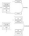
도 3은 협력 통신의 다른 예로서 Distributed Antenna System(DAS) 및 remote radio head(RRH)를 나타낸 도면이다.3 is a diagram illustrating a Distributed Antenna System (DAS) and a remote radio head (RRH) as another example of cooperative communication.
도 3을 참조하면, DAS(310)는 물리적으로 서로 떨어진 안테나 모듈들을 포함한다. DAS(310)는 서로 떨어진 안테나 모듈들에 대하여 분산된 MIMO(Multiple Input Multiple Output) 기술을 적용함으로써 셀간 간섭을 줄일 수 있다.Referring to FIG. 3, the DAS 310 includes antenna modules that are physically separated from each other. The
또한, RRH(320)는 RRC 계층에서 신호를 처리하기 위한 처리 모듈, MAC 계층에서 신호를 처리하기 위한 처리 모듈 및 PHY 계층에서의 신호를 처리하기 위한 처리 모듈로 구성된 기저 대역 장치(320의 왼쪽에 도시된)를 포함한다. 그리고, RRH(320)는 RF 단과 안테나 모듈을 각각 포함하는 두 개의 RF-안테나 장치들(320의 오른쪽에 도시된)을 포함한다.In addition, the
이 때, DAS(310) 및 RRH(320)는 하나의 기지국을 단순히 확장한 형태를 가지므로, 이론적으로 하나의 기지국이 달성할 수 있는 최대 성능보다 높은 성능을 달성할 수 없다.At this time, since the DAS 310 and the RRH 320 simply extend one base station, it is theoretically impossible to achieve higher performance than the maximum performance that one base station can attain.
결국, 도 2 및 도 3과 관련하여 설명한 바와 같이, 협력 멀티 포인트 송/수신 기술, DAS 및 RRH는 여러 한계들을 갖는다. 아래에서는 이러한 한계들을 개선하면서 최적화된 망접속 구조를 갖는 통신 시스템을 제안한다.As a result, as described in connection with FIGS. 2 and 3, the cooperative multipoint transmit / receive technology, DAS and RRH have various limitations. In the following, we propose a communication system with optimized network connection structure while improving these limitations.
도 4 내지 도 6을 통하여 셀들을 분리 또는 통합함으로써 형성되는 가상 셀의 개념에 대해 간단히 설명한다. 그리고, 중앙 장치(central unit) 및 무선 접속 장치(Radio Access Unit, RAU)들의 구체적인 동작에 대해서는 도 7 내지 도 14를 통해 설명한다.The concept of a virtual cell formed by separating or integrating cells through FIGS. 4 to 6 will be briefly described. Specific operations of the central unit and the radio access unit (RAU) will be described with reference to FIGS. 7 to 14. FIG.
- 분리된 셀(separated cell)- Separated cells
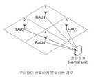
도 4는 복수의 무선 접속 장치들 및 중앙 장치를 포함하는 다중 셀 통신 시스템에서, 셀들 각각에 가해지는 부하량이 균일하게 분포하는 경우를 나타낸 도면이다.4 is a diagram showing a case where a load applied to each cell is uniformly distributed in a multi-cell communication system including a plurality of radio access devices and a central device.
도 4를 참조하면, 무선 접속 장치 1, 2, 3, 4는 중앙 장치와 연결되며, 무선 접속 장치(Radio Access Unit) 1, 2, 3, 4 각각은 하나의 (물리적) 셀을 형성한 다. 즉, RAU 1, 2, 3, 4 각각은 셀 1, 2, 3, 4 각각을 형성하며, 셀 1, 2, 3, 4은 서로 통합되거나 분리됨으로써 가상 셀을 형성할 수 있는데, 도 4에서 셀 1, 2, 3, 4은 각각은 서로 분리되어서 하나의 가상 셀을 형성한다. 다만, 셀들 각각에 가해지는 부하량이 균일한 경우에도, 도 4에 도시된 것과 다르게 무선 접속 장치들의 셀들 각각은 서로 통합되서 가상 셀을 형성할 수도 있다.Referring to FIG. 4, the
- 통합된 셀(merged cell)- merged cell
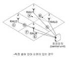
도 5는 다중 셀 통신 시스템에서 특정 셀(무선 접속 장치 3의 셀)에 단말이 존재하지 않는 경우를 나타낸 도면이다.5 is a diagram illustrating a case where a terminal does not exist in a specific cell (a cell of the radio access station 3) in the multi-cell communication system.
도 5를 참조하면, 도 4를 통해 설명한 바와 마찬가지로, 무선 접속 장치 1, 2, 3, 4는 중앙 장치와 연결되며, 무선 접속 장치 1, 2, 3, 4 각각은 하나의 셀을 형성한다.Referring to FIG. 5, the
셀 1, 2, 4 각각에는 단말 A, B, C 각각이 존재하지만, 셀 3에는 어떠한 단말도 존재하지 아니한다. 이 때, 셀 1과 셀 3은 서로 통합되어서 하나의 가상 셀을 형성할 수 있다. 도 5에서 '점선'은 서로 통합된 셀을 의미한다.Each of
이 때, RAU 3은 단말 A에 대한 용량이 개선될 수 있도록 RAU 1과 협력하여 단말 A를 서빙할 수 있다. 특히, 단말 A의 채널의 상태가 좋지 않거나, 단말 A가 높은 서비스 품질 또는 높은 데이터 전송률을 요구하는 경우, RAU 3는 RAU 1과 협력할 수 있다.At this time, the
특히, 셀 1 및 셀 3이 하나의 가상 셀로 통합되는 경우, 단말 A가 셀 3으로 이동하더라도 핸드오버가 일어나지 않는다. 왜냐 하면, 셀 1 및 셀 3을 통합하는 가상 셀은 하나의 식별자를 사용하기 때문이다.In particular, when
- 부분적으로 통합된 셀(Partially-merged cell)- Partially-merged cell.
도 6은 다중 셀 통신 시스템에서 다른 셀들보다 특정 셀에 작은 양의 부하가 걸리는 경우를 나타낸 도면이다.6 is a diagram illustrating a case where a small amount of load is applied to a particular cell in a multi-cell communication system than other cells.
도 6을 참조하면, 셀 1, 2, 4 각각에는 두 개의 단말들이 존재하는 반면, 셀 3에는 하나의 단말이 존재함을 알 수 있다. 보다 구체적으로, 셀 1에는 단말 A, B, 셀 2에는 단말 C, D, 셀 4에는 단말 F, E가 존재하는 반면에, 셀 3에는 단말 G가 존재한다.Referring to FIG. 6, it can be seen that there are two terminals in each of
단말들 각각에 의한 부하량이 동일하다면, 셀 1, 2, 4보다 셀 3에 작은 양의 부하가 걸리며, 셀 3은 잉여의 무선 자원을 가질 수 있다. 이 때, RAU 3은 단말 G를 서빙할 뿐만 아니라, 잉여의 무선 자원을 이용하여 단말 A, B를 RAU 1과 함께 서빙할 수 있다.If the load by each of the terminals is the same, a small amount of load is applied to the
결국, 단말 A, B의 입장에서 셀 1 및 셀 3은 통합되는 반면, 단말 G의 입장에서 셀 1 및 셀 3 각각은 서로 독립된 셀로 간주된다.As a result,
도 7은 본 발명의 일실시예에 따른 중앙 장치, 무선 접속 장치들 및 가상 셀들을 나타낸 도면이다.7 is a diagram illustrating a central device, wireless connection devices, and virtual cells according to an embodiment of the present invention.
도 8은 제1 처리 모듈 및 제2 처리 모듈에 포함되는 기능들을 나타낸 도표 이다.8 is a chart showing the functions included in the first processing module and the second processing module.
도 7을 참조하면, 중앙 장치(710)는 중앙 컨트롤러, 여러 개의 제1 처리 모듈들 및 스위치를 포함하며, 무선 접속 장치들(720) 각각은 제2 처리 모듈을 포함한다. 또한, 무선 접속 장치들(720)은 서로 통합되거나, 분리되어서 가상 셀들(730)을 형성한다. 보다 구체적으로, 무선 접속 장치(721)는 독립적으로 가상 셀 1(VC 1)을, 무선 접속 장치(722) 및 무선 접속 장치(723)은 서로 통합되어 가상 셀 2(VC 2)를, 무선 접속 장치(724), 무선 접속 장치(725)7, the central device 710 includes a central controller, a plurality of first processing modules and a switch, and each of the wireless connection devices 720 includes a second processing module. Further, the wireless connection devices 720 are integrated with each other or separated to form the virtual cells 730. More specifically, the
및 무선 접속 장치(726)은 서로 통합되어 가상 셀 3(VC 3)을 형성한다. And
도 8을 참조하면, 제1 처리 모듈 및 제2 처리 모듈은 서로 다른 기능들을 수행할 수 있다.Referring to FIG. 8, the first processing module and the second processing module may perform different functions.
첫 번째 예에 따르면, 제1 처리 모듈은 RRC 계층, MAC 계층, PHY 계층에서의 신호 처리를 수행하며, 제2 처리 모듈은 무선 주파수 신호 및 기저 대역 신호 사이의 변환을 수행하는 RF 단 및 무선 주파수 신호를 송/수신하는 안테나 모듈을 포함한다. 첫 번째 예에 따르는 경우, 제1 처리 모듈 및 제2 처리 모듈 사이의 링크를 통해서는 기저 대역 신호가 지나간다.According to a first example, the first processing module performs signal processing in the RRC layer, the MAC layer, and the PHY layer, and the second processing module performs processing in the RF step and the radio frequency And an antenna module for transmitting / receiving a signal. In accordance with the first example, the baseband signal passes through the link between the first processing module and the second processing module.
두 번째 예에 따르면, 제1 처리 모듈은 RRC 계층, MAC 계층, PHY 계층에서의 신호 처리를 수행할 뿐만 아니라, RF 단을 포함한다. 반면에, 제2 처리 모듈은 안테나 모듈만을 포함한다. 이 때, 제1 처리 모듈 및 제2 처리 모듈 사이의 링크를 통해서는 무선 주파수 신호가 지나간다.According to the second example, the first processing module not only performs signal processing in the RRC layer, the MAC layer, and the PHY layer, but also includes an RF stage. On the other hand, the second processing module includes only the antenna module. At this time, the radio frequency signal passes through the link between the first processing module and the second processing module.
다시 도 7을 참조하면, 중앙 장치(710)의 중앙 컨트롤러는 협력 통신을 위해 무선 접속 장치들(720)의 셀들 중 적어도 두 개의 셀들을 통합(merging)하여 적어도 하나의 가상 셀을 구성할 수 있다. 예를 들어, 중앙 컨트롤러는 무선 접속 장치(722) 및 무선 접속 장치(723)를 서로 통합하여 가상 셀 2(VC 2)를, 무선 접속 장치(724), 무선 접속 장치(725) 및 무선 접속 장치(726)를 서로 통합하여 가상 셀 3(VC 3)을 형성한다.Referring again to FIG. 7, the central controller of the central device 710 may configure at least one virtual cell by merging at least two of the cells of the wireless access devices 720 for cooperative communication . For example, the central controller combines the
반면에, 중앙 컨트롤러는 무선 접속 장치들의 셀들 각각을 분리할 수 있는데, 도 7에서 가상 셀 1은 분리된 셀이다.On the other hand, the central controller can separate each of the cells of the wireless access devices, where
이 때, 중앙 컨트롤러는 무선 접속 장치들(720)에 의해 서빙되는 단말들의 분포, 무선 접속 장치들(720)과 단말들 사이의 채널들의 상태 또는 단말들을 위한 트래픽의 양 중 적어도 하나를 고려하여 통합 또는 분리 중 어느 하나를 결정할 수 있다. 예를 들어, 중앙 컨트롤러는 단말들의 핸드오버가 일어나는 횟수가 감소되도록, 단말들의 요구하는 서비스 품질이 최대한 만족하도록, 무선 자원의 사용 효율이 극대화되도록 가상 셀들을 구성할 수 있다.At this time, the central controller determines whether or not to integrate the wireless communication devices 720 considering the distribution of the terminals served by the wireless access devices 720, the state of the channels between the wireless access devices 720 and the terminals, Or separation may be determined. For example, the central controller can configure the virtual cells such that the use efficiency of the radio resources is maximized such that the number of times of handover of the terminals is reduced, so that the service quality required by the terminals is maximally satisfied.
중앙 컨트롤러에 의해 가상 셀이 구성되면, 스위치는 제1 처리 모듈들과 무선 접속 장치들(720)의 제2 처리 모듈들을 적절히 연결한다. 즉, 무선 접속 장치(721)는 분리된 셀로서 가상 셀 1을 형성하므로, 중앙 장치(710)에 포함된 하나의 제1 처리 모듈과 연결된다. 또한, 무선 접속 장치(722) 및 무선 접속 장치(723)는 서로 통합되어서 하나의 가상 셀 2를 형성하므로, 스위치는 무선 접속 장치(722) 및 무선 접속 장치(723)를 하나의 제1 처리 모듈과 연결한다. 뿐만 아니라, 무선 접속 장치(724), 무선 접속 장치(725) 및 무선 접속 장치(726) 또한 서로 통합되어서 하나의 가상 셀 3을 형성하므로 하나의 제1 처리 모듈과 연결된다.When a virtual cell is configured by the central controller, the switch appropriately couples the first processing modules and the second processing modules of the wireless connection devices 720. That is, since the
이 때, 무선 접속 장치들(720)에 포함된 제2 처리 모듈들 및 그들과 적절히 연결된 제1 처리 모듈은 실질적으로 하나의 기지국으로서 동작할 수 있다. 예를 들어, 무선 접속 장치(724), 무선 접속 장치(725) 및 무선 접속 장치(726) 및 상기 무선 접속 장치들(724, 725, 726)과 연결된 제1 처리 모듈은 가상 셀 3에서 마치 하나의 기지국처럼 동작할 수 있다. 마찬가지로, 무선 접속 장치(722) 및 무선 접속 장치(723) 및 상기 무선 접속 장치들(722, 723)과 연결된 제1 처리 모듈은 가상 셀 2에서 마치 하나의 기지국처럼 동작할 수 있다.At this time, the second processing modules included in the wireless connection devices 720 and the first processing module suitably connected thereto can operate as substantially one base station. For example, the first processing module coupled to the
도 9는 본 발명의 일실시예에 따른 중앙 장치를 나타낸 블록도이다.9 is a block diagram illustrating a central apparatus according to an embodiment of the present invention.
도 9를 참조하면, 중앙 장치는 백홀 인터페이스, 데이터베이스, 가상 셀 매니저, 이동성 매니저, 셀간 간섭 코디네이터, QoS 매니저, 제1 처리 모듈 인터페이스, 여러 제1 처리 모듈들 및 스위치를 포함한다.Referring to FIG. 9, the central apparatus includes a backhaul interface, a database, a virtual cell manager, a mobility manager, an intercell interference coordinator, a QoS manager, a first processing module interface, and various first processing modules and switches.
백홀 인터페이스는 유선/무선을 통하여 다른 중앙 장치와 통신하기 위한 인터페이스를 제공한다.The backhaul interface provides an interface for communicating with other central devices via wired / wireless.
또한, 데이터베이스는 복수의 무선 접속 장치들 및 단말들 사이의 채널들의 상태에 대한 정보 및 단말들을 위한 트래픽의 양에 대한 정보를 저장 및 관리한다. 뿐만 아니라, 데이터베이스는 무선 접속 장치들에 의해 서빙되는 단말들의 분포에 대한 정보(예를 들어, 단말들의 위치에 대한 정보)를 더 저장 및 관리할 수 있다. 데이터베이스에 저장된 정보는 가상 셀들을 형성하거나, 간섭 제어 기술들을 적용하는 데에 사용된다.In addition, the database stores and manages information on the state of channels between a plurality of wireless access devices and terminals, and information on the amount of traffic for the terminals. In addition, the database may further store and manage information about the distribution of terminals served by the wireless access devices (e.g., information about the location of the terminals). The information stored in the database is used to form virtual cells or to apply interference control techniques.
가상 셀 매니저는 형성된 가상 셀들을 관리한다. 보다 구체적으로, 가상 셀 매니저는 가상 셀들의 식별자들, 가상 셀들의 변화 등을 관리한다.The virtual cell manager manages the formed virtual cells. More specifically, the virtual cell manager manages identifiers of virtual cells, changes in virtual cells, and the like.
또한, 이동성 매니저는 가상 셀들 사이에서 단말들의 이동성과 관련된 정보, 가상 셀들의 변화로 인한 단말의 상대적인 위치 변화 등과 관련된 정보 등을 수집한다.Also, the mobility manager collects information related to the mobility of the terminals among the virtual cells, information related to the relative position change of the terminal due to the change of the virtual cells, and the like.
또한, 셀간 간섭 코디네이터는 형성된 가상 셀들 사이에서 발생하는 간섭을 제어한다. 특히, 셀간 간섭 코디네이터는 다양한 간섭 제어 기술들(예를 들어, 송신 전력 제어 기술, 간섭 정렬 기술, 다중 셀 MIMO 기술) 중 적절한 것을 선택 및 적용한다.In addition, the inter-cell interference coordinator controls the interference occurring between the formed virtual cells. In particular, the intercell interference coordinator selects and applies a variety of interference control techniques (e.g., transmit power control techniques, interference alignment techniques, multi-cell MIMO techniques).
또한, QoS 매니저는 단말들의 우선도(priority) 또는 요구되는 서비스 품질을 관리한다. 즉, 단말들의 우선도 및 요구되는 서비스 품질은 다를 수 있는데, QoS 매니저는 그 단말들의 우선도 및 요구되는 서비스 품질에 대한 정보를 저장 및 관리한다. 이러한 정보는 다양한 간섭 제어 기술들 중 어느 하나를 선택하거나, 가상 셀들을 형성하는 과정에서 사용된다.In addition, the QoS manager manages the priorities of the terminals or the required quality of service. That is, the priorities of the terminals and the required service quality may be different, and the QoS manager stores and manages the priorities of the terminals and information on the required service quality. This information is used in the process of selecting any one of various interference control techniques or forming virtual cells.
도 10은 제1 처리 모듈의 기능 및 제2 처리 모듈의 기능 모두를 수행하는 제3 처리 모듈을 포함하는 무선 접속 장치가 존재하는 경우, 중앙 장치 및 무선 접 속 장치들의 관계를 나타낸 도면이다.10 is a diagram illustrating a relationship between a central device and wireless connection devices when there is a wireless connection device including a third processing module that performs both the functions of the first processing module and the second processing module.
도 10을 참조하면, 무선 접속 장치들(1021, 1022, 1023) 중 무선 접속 장치들(1021, 1022)는 제3 처리 모듈을 포함한다. 제3 처리 모듈은 제1 처리 모듈의 기능 및 제2 처리 모듈의 기능을 모두 수행할 수 있는 모듈로서, 보다 구체적으로 RRC 계층, MAC 계층, PHY 계층에서의 신호 처리를 수행할 수 있고, RF 단 및 무선 주파수 신호를 송/수신하는 안테나 모듈을 포함한다. 제3 처리 모듈을 이용하여 동작하는 무선 접속 장치는 하나의 독립된 기지국처럼 동작하며, 잘 알려진 피코 기지국, 펨토 기지국과 동일 또는 유사한 기능들을 수행한다.Referring to FIG. 10, the
무선 접속 장치(1021)는 분리된 셀로서, 하나의 가상 셀 1을 형성한다. 이 때, 무선 접속 장치(1021)는 제3 처리 모듈을 포함하고 있으므로, 중앙 장치(1010)의 제1 처리 모듈과 연결되지 않아도 된다. 따라서, 중앙 장치(1010)의 스위치는 무선 접속 장치(1021)를 직접 중앙 컨트롤러에 연결한다.The
또한, 무선 접속 장치(1022) 및 무선 접속 장치(1023)는 서로 통합되어서 하나의 가상 셀 2를 형성한다. 이 때, 스위치는 무선 접속 장치(1022)의 제2 처리 모듈 및 무선 접속 장치(1023)의 제2 처리 모듈을 중앙 장치(1010)의 제1 처리 모듈과 연결한다. 이 때, 무선 접속 장치(1022)의 제2 처리 모듈 및 무선 접속 장치(1023)의 제2 처리 모듈 및 중앙 장치(1010)의 제1 처리 모듈은 서로 협력하여 가상 셀 2를 위한 실질적인 기지국의 기능을 수행한다.In addition, the
도 11은 제1 처리 모듈의 기능 및 제2 처리 모듈의 기능 모두를 수행하는 제3 처리 모듈을 포함하고, 다른 무선 접속 장치에게 필요한 제1 처리 모듈의 기능을 대신 수행할 수 있는 무선 접속 장치가 존재하는 경우, 중앙 장치 및 무선 접속 장치들의 관계를 나타낸 도면이다.11 is a block diagram of a wireless communication system according to another embodiment of the present invention, which includes a third processing module that performs both a function of the first processing module and a function of the second processing module, If present, the relationship between the central unit and the wireless access devices.
도 11을 참조하면, 제2 처리 모듈뿐만 아니라 제3 처리 모듈을 포함하는 무선 접속 장치(1121)는 마스터로 동작하며, 제2 처리 모듈만을 포함하는 무선 접속 장치(1122)는 슬레이브로 동작한다.Referring to FIG. 11, the
즉, 무선 접속 장치(1121)에 포함된 제3 처리 모듈은 중앙 장치(1110)를 대신하여 무선 접속 장치(1122)에게 부족한 제1 처리 모듈의 기능을 대신 수행한다. 즉, 무선 접속 장치(1122)의 제2 처리 모듈 및 무선 접속 장치(1121)의 제3 처리 모듈은 무선 접속 장치(1121)의 스위치를 통해 서로 연결되며, 무선 접속 장치(1121)의 제3 처리 모듈은 중앙 장치(1110)의 스위치를 통하여 중앙 컨트롤러와 연결된다.That is, the third processing module included in the
이 때, 중앙 장치(1110)의 제1 처리 모듈들의 도움이 없더라도, 무선 접속 장치(1121) 및 무선 접속 장치(1122)는 서로 협력하여 가상 셀 4를 위한 기지국의 기능들을 모두 수행할 수 있다.At this time, the
또한, 도 11에 도시된 것과 다르게, 무선 접속 장치(1121)는 중앙 컨트롤러의 기능들을 수행하기 위한 모듈을 포함할 수 있으며, 이러한 경우, 중앙 장치(1110)과 무선 접속 장치(1121)가 서로 연결되지 않을 수 있다.11, the
도 12는 가상 셀들을 구성하기 위하여 서로 연결되는 두 개의 중앙 장치들 을 포함하는 통신 시스템을 나타낸 도면이다.12 is a diagram of a communication system including two central devices connected together to form virtual cells.
도 12를 참조하면, 두 개의 중앙 장치들(1210, 1220)은 서로 연결되어 여러 가상 셀들을 위한 동작을 수행할 수 있다.Referring to FIG. 12, the two
무선 접속 장치(1231)는 분리된 셀로서, 가상 셀 1을 형성한다. 이 때, 무선 접속 장치(1231)는 제3 처리 모듈을 포함하고 있으므로, 독립적인 기지국으로 동작할 수 있으며, 스위치를 통하여 중앙 장치(1210)의 중앙 컨트롤러와 직접 연결된다.The
또한, 무선 접속 장치들(1232, 1233, 1241)은 서로 통합되어 하나의 가상 셀 2를 형성한다. 이 때, 무선 접속 장치(1232)의 제2 처리 모듈 및 무선 접속 장치(1233)의 제2 처리 모듈은 중앙 장치(1210)의 스위치를 통하여 중앙 장치(1210)의 제1 처리 모듈과 연결된다. 또한, 무선 접속 장치(1241)는 제3 처리 모듈을 포함하고 있으므로, 중앙 장치(1220)의 중앙 컨트롤러와 직접 연결된다. 결국, 무선 접속 장치(1232) 및 무선 접속 장치(1233)가 하나의 독립된 기지국으로 동작할 수 있고, 무선 접속 장치(1241)가 다른 하나의 독립된 기지국으로 동작할 수 있다. 이 때, 두 개의 기지국들 각각은 중앙 장치들(1210, 1220)과 연결되며, 중앙 장치들(1210, 1220)은 서로 연결되므로, 세 개의 무선 접속 장치들(1232, 1233, 1241)을 통합하여 생성된 하나의 가상 셀 2는 두 개의 독립된 기지국들을 기초로 형성된 것으로 간주될 수도 있다.Also, the
또한, 무선 접속 장치(1242) 및 무선 접속 장치(1243)는 서로 통합되어 가상 셀 3을 형성할 수 있고, 무선 접속 장치(1242)에 포함된 제2 처리 모듈 및 무선 접속 장치(1243)에 포함된 제2 처리 모듈은 스위치를 통하여 중앙 장치(1220)의 제1 처리 모듈과 연결된다.The
도 13은 중앙 장치 없이도 중앙 장치의 기능을 수행하는 무선 접속 장치들을 포함하는 통신 시스템을 나타낸 도면이다.13 is a diagram illustrating a communication system including wireless connection devices that perform the function of a central device without a central device.
여기서, 무선 접속 장치(1310) 및 무선 접속 장치(1330) 중 적어도 하나는 중앙 장치의 기능들을 수행할 수 있도록 설계되었음을 가정한다.Here, it is assumed that at least one of the
도 13을 참조하면, 중앙 장치 없어도 네 개의 무선 접속 장치들(1310, 1320, 1330, 1340)은 서로 통합되어 하나의 가상 셀 1을 형성할 수 있다. 이 때, 무선 접속 장치(1310) 및 무선 접속 장치(1330) 각각은 무선 접속 장치(1320) 및 무선 접속 장치(1340) 각각에 대한 마스터로 동작한다.13, four
무선 접속 장치(1310) 및 무선 접속 장치(1320)는 서로 통합되어서 독립적인 하나의 기지국으로 기능할 수 있고, 무선 접속 장치(1330) 및 무선 접속 장치(1340) 역시 서로 통합되어서 독립적인 다른 하나의 기지국으로 기능할 수 있다. 이 때, 두 개의 기지국들은 서로 통합되어서 하나의 가상 셀 1을 형성한다.The
도 14는 본 발명의 일실시예에 따른 통신 시스템의 동작 방법을 나타낸 동작 흐름도이다.14 is a flowchart illustrating an operation method of a communication system according to an embodiment of the present invention.
도 14와 관련하여 설명하기에 앞서, 단말은 RAU 2의 셀 커버리지에 속한다고 가정한다.Prior to the description with reference to FIG. 14, it is assumed that the UE belongs to the cell coverage of
도 14를 참조하면, RAU 1은 단말에게 간섭을 끼친다. 이 때, 단말은 RAU 1로 인한 간섭을 측정할 수 있다. 뿐만 아니라, 단말은 RAU 2로부터 단말로의 채널을 측정할 수 있다.Referring to FIG. 14,
그리고, 단말은 요구하는 데이터 전송률, 요구하는 서비스 품질, RAU 2로부터 단말로의 채널의 상태 또는 RAU 1로 인한 간섭의 양에 대한 정보를 RAU 2로 보고한다.Then, the terminal reports information on the requested data rate, the requested quality of service, the state of the channel from
이러한 여러 정보들이 수집되면, 중앙 장치, RAU 1 및 RAU 2 중 적어도 하나는 RAU 1의 셀 및 RAU2의 셀을 하나의 가상 셀로 통합할 것인지 또는 두 개의 가상 셀들로 분리할 것인지 여부를 결정한다. 만약, 분리한다면, 단말은 RAU 2와 통상적인 방법에 따라 통신을 지속한다.When this information is collected, at least one of the central unit,
반대로, RAU 1의 셀 및 RAU2의 셀을 통합하는 것으로 결정된다면, RAU 2는 셀들의 통합을 알리기 위하여 메시지 'merging ready'를 전송한다. 이 때, 단말은 'merging ready'에 응답하여 'merging ACK'를 RAU 2로 전달한다.Conversely, if it is determined to integrate the cells of
그리고, RAU 2는 가상 셀에 대한 정보를 메시지 'merging cell info'로서 단말로 전송한다. 여기서, 가상 셀에 대한 정보 형성된 가상 셀의 식별자를 포함한다. 즉, 통합된 셀이 형성된 경우, RAU 1의 셀의 식별자 및 RAU2의 셀의 식별자는 가상 셀의 식별자로 통합된다. 따라서, 단말은 통합된 가상 셀에서 이동하더라도 핸드오버가 요구되지 않는다.
또한, 단말은 메시지 'merging cell info'에 응답하여 메시지 'merging cell info ACK'를 전송한다. 이후에, 중앙 장치, RAU 1 및 RAU 2는 셀들을 통합하 여 하나의 가상 셀을 형성한다. 그리고, RAU 1 및 RAU 2는 단말과의 통신을 위하여 다양한 유형의 제어 정보를 브로드캐스트하며, 그 제어 정보에 따라 통신 초기화 과정이 실행된다.In addition, the UE transmits a message 'merging cell info ACK' in response to a message 'merging cell info'. Then, the central unit,
도 15는 본 발명의 실시예들에 따른 중앙 장치 및 무선 접속 장치들이 적용될 수 있는 예를 나타낸 도면이다.15 is a diagram illustrating an example in which a central apparatus and wireless connection apparatuses according to embodiments of the present invention can be applied.
도 15를 참조하면, 건물 내에는 복수의 무선 접속 장치들이 설치되며, 그 무선 접속 장치들은 중앙 장치와 연결된다. 이 때, 중앙 장치는 인터넷과 연결된다.Referring to FIG. 15, a plurality of wireless connection devices are installed in a building, and the wireless connection devices are connected to a central device. At this time, the central apparatus is connected to the Internet.
본 발명의 실시예들은 도 15에 도시된 여러 무선 접속 장치들을 요구하는 건물 등에 잘 적용될 수 있다.The embodiments of the present invention can be applied well to a building or the like requiring a plurality of wireless connection devices shown in FIG.
본 발명에 따른 방법들은 다양한 컴퓨터 수단을 통하여 수행될 수 있는 프로그램 명령 형태로 구현되어 컴퓨터 판독 가능 매체에 기록될 수 있다. 상기 컴퓨터 판독 가능 매체는 프로그램 명령, 데이터 파일, 데이터 구조 등을 단독으로 또는 조합하여 포함할 수 있다. 상기 매체에 기록되는 프로그램 명령은 본 발명을 위하여 특별히 설계되고 구성된 것들이거나 컴퓨터 소프트웨어 당업자에게 공지되어 사용 가능한 것일 수도 있다. 컴퓨터 판독 가능 기록 매체의 예에는 하드 디스크, 플로피 디스크 및 자기 테이프와 같은 자기 매체(magnetic media), CD-ROM, DVD와 같은 광기록 매체(optical media), 플롭티컬 디스크(floptical disk)와 같은 자기-광 매체(magneto-optical media), 및 롬(ROM), 램(RAM), 플래시 메모리 등과 같은 프로그램 명령을 저장하고 수행하도록 특별히 구성된 하드웨어 장치가 포함된다. 프로그램 명령의 예에는 컴파일러에 의해 만들어지는 것과 같은 기계어 코드뿐만 아니라 인터프리터 등을 사용해서 컴퓨터에 의해서 실행될 수 있는 고급 언어 코드를 포함한다. 상기된 하드웨어 장치는 본 발명의 동작을 수행하기 위해 하나 이상의 소프트웨어 모듈로서 작동하도록 구성될 수 있으며, 그 역도 마찬가지이다.The methods according to the present invention may be implemented in the form of program instructions that can be executed through various computer means and recorded in a computer-readable medium. The computer-readable medium may include program instructions, data files, data structures, and the like, alone or in combination. The program instructions recorded on the medium may be those specially designed and configured for the present invention or may be available to those skilled in the art of computer software. Examples of computer-readable media include magnetic media such as hard disks, floppy disks, and magnetic tape; optical media such as CD-ROMs and DVDs; magnetic media such as floppy disks; Magneto-optical media, and hardware devices specifically configured to store and execute program instructions such as ROM, RAM, flash memory, and the like. Examples of program instructions include machine language code such as those produced by a compiler, as well as high-level language code that can be executed by a computer using an interpreter or the like. The hardware devices described above may be configured to operate as one or more software modules to perform the operations of the present invention, and vice versa.
이상과 같이 본 발명은 비록 한정된 실시예와 도면에 의해 설명되었으나, 본 발명은 상기의 실시예에 한정되는 것은 아니며, 본 발명이 속하는 분야에서 통상의 지식을 가진 자라면 이러한 기재로부터 다양한 수정 및 변형이 가능하다.While the invention has been shown and described with reference to certain preferred embodiments thereof, it will be understood by those of ordinary skill in the art that various changes in form and details may be made therein without departing from the spirit and scope of the invention as defined by the appended claims. This is possible.
그러므로, 본 발명의 범위는 설명된 실시예에 국한되어 정해져서는 아니 되며, 후술하는 특허청구범위뿐 아니라 이 특허청구범위와 균등한 것들에 의해 정해져야 한다.Therefore, the scope of the present invention should not be limited to the described embodiments, but should be determined by the equivalents of the claims, as well as the claims.
도 1은 다중 셀(계층 셀) 통신 시스템의 예를 나타낸 도면이다.1 is a diagram showing an example of a multi-cell (layer cell) communication system.
도 2는 협력 통신의 예로서 협력 멀티 포인트(Coordinated Multi-Point: CoMP) 송/수신을 수행하는 두 개의 기지국들을 나타낸 도면이다.2 is a diagram showing two base stations performing Coordinated Multi-Point (CoMP) transmission / reception as an example of cooperative communication.
도 3은 협력 통신의 다른 예로서 Distributed Antenna System(DAS) 및 remote radio head(RRH)를 나타낸 도면이다.3 is a diagram illustrating a Distributed Antenna System (DAS) and a remote radio head (RRH) as another example of cooperative communication.
도 4는 복수의 무선 접속 장치들 및 중앙 장치를 포함하는 다중 셀 통신 시스템에서, 부하량이 셀들 각각에 균일하게 분포하는 경우를 나타낸 도면이다.4 is a diagram showing a case where a load is uniformly distributed in each of the cells in a multi-cell communication system including a plurality of wireless connection devices and a central device.
도 5는 다중 셀 통신 시스템에서 특정 셀(무선 접속 장치 3의 셀)에 단말이 존재하지 않는 경우를 나타낸 도면이다.5 is a diagram illustrating a case where a terminal does not exist in a specific cell (a cell of the radio access station 3) in the multi-cell communication system.
도 6은 다중 셀 통신 시스템에서 다른 셀들보다 특정 셀에 작은 양의 부하가 걸리는 경우를 나타낸 도면이다.6 is a diagram illustrating a case where a small amount of load is applied to a particular cell in a multi-cell communication system than other cells.
도 7은 본 발명의 일실시예에 따른 중앙 장치, 무선 접속 장치들 및 가상 셀들을 나타낸 도면이다.7 is a diagram illustrating a central device, wireless connection devices, and virtual cells according to an embodiment of the present invention.
도 8은 제1 처리 모듈 및 제2 처리 모듈에 포함되는 기능들을 나타낸 도표이다.8 is a chart showing the functions included in the first processing module and the second processing module.
도 9는 본 발명의 일실시예에 따른 중앙 장치를 나타낸 블록도이다.9 is a block diagram illustrating a central apparatus according to an embodiment of the present invention.
도 10은 제1 처리 모듈의 기능 및 제2 처리 모듈의 기능 모두를 수행하는 제3 처리 모듈을 포함하는 무선 접속 장치가 존재하는 경우, 중앙 장치 및 무선 접속 장치들의 관계를 나타낸 도면이다.10 is a diagram illustrating a relationship between a central apparatus and a wireless connection apparatus when a wireless connection apparatus including a third processing module performing both the functions of the first processing module and the second processing module exists.
도 11은 제1 처리 모듈의 기능 및 제2 처리 모듈의 기능 모두를 수행하는 제3 처리 모듈을 포함하고, 다른 무선 접속 장치에게 필요한 제1 처리 모듈의 기능을 대신 수행할 수 있는 무선 접속 장치가 존재하는 경우, 중앙 장치 및 무선 접속 장치들의 관계를 나타낸 도면이다.11 is a block diagram of a wireless communication system according to another embodiment of the present invention, which includes a third processing module that performs both a function of the first processing module and a function of the second processing module, If present, the relationship between the central unit and the wireless access devices.
도 12는 가상 셀들을 구성하기 위하여 서로 연결되는 두 개의 중앙 장치들을 포함하는 통신 시스템을 나타낸 도면이다.12 shows a communication system including two central devices connected together to form virtual cells.
도 13은 중앙 장치 없이도 중앙 장치의 기능을 수행하는 무선 접속 장치들을 포함하는 통신 시스템을 나타낸 도면이다.13 is a diagram illustrating a communication system including wireless connection devices that perform the function of a central device without a central device.
도 14는 본 발명의 일실시예에 따른 통신 시스템의 동작 방법을 나타낸 동작 흐름도이다.14 is a flowchart illustrating an operation method of a communication system according to an embodiment of the present invention.
Claims (18)
Translated fromKoreanPriority Applications (6)
| Application Number | Priority Date | Filing Date | Title |
|---|---|---|---|
| KR1020090102694AKR101585067B1 (en) | 2009-10-28 | 2009-10-28 | Communication system having network access structure |
| US12/785,039US8412206B2 (en) | 2009-10-28 | 2010-05-21 | Communication system having network access structure |
| CN201080047577.8ACN102668616B (en) | 2009-10-28 | 2010-06-11 | Communication system with network access structure |
| EP10826955.6AEP2494810B1 (en) | 2009-10-28 | 2010-06-11 | Communication system having network access structure |
| PCT/KR2010/003758WO2011052870A1 (en) | 2009-10-28 | 2010-06-11 | Communication system having network access structure |
| JP2012536644AJP5681994B2 (en) | 2009-10-28 | 2010-06-11 | Central apparatus in communication system having network connection structure, and operation method of terminal |
Applications Claiming Priority (1)
| Application Number | Priority Date | Filing Date | Title |
|---|---|---|---|
| KR1020090102694AKR101585067B1 (en) | 2009-10-28 | 2009-10-28 | Communication system having network access structure |
Publications (2)
| Publication Number | Publication Date |
|---|---|
| KR20110045936A KR20110045936A (en) | 2011-05-04 |
| KR101585067B1true KR101585067B1 (en) | 2016-01-13 |
Family
ID=43898382
Family Applications (1)
| Application Number | Title | Priority Date | Filing Date |
|---|---|---|---|
| KR1020090102694AActiveKR101585067B1 (en) | 2009-10-28 | 2009-10-28 | Communication system having network access structure |
Country Status (6)
| Country | Link |
|---|---|
| US (1) | US8412206B2 (en) |
| EP (1) | EP2494810B1 (en) |
| JP (1) | JP5681994B2 (en) |
| KR (1) | KR101585067B1 (en) |
| CN (1) | CN102668616B (en) |
| WO (1) | WO2011052870A1 (en) |
Families Citing this family (39)
| Publication number | Priority date | Publication date | Assignee | Title |
|---|---|---|---|---|
| US11451275B2 (en) | 2004-04-02 | 2022-09-20 | Rearden, Llc | System and method for distributed antenna wireless communications |
| KR101472100B1 (en)* | 2010-12-22 | 2014-12-11 | 주식회사 케이티 | Base station apparatus and data processing method in wireless communication system |
| ES2405735B1 (en)* | 2011-05-17 | 2014-05-13 | Telefónica, S.A. | SYSTEM AND METHOD TO MINIMIZE INTERFERENCES BETWEEN NODES OFRADIO ACCESS OF A RADIO ACCESS NETWORK |
| WO2012169799A2 (en)* | 2011-06-07 | 2012-12-13 | 한국전자통신연구원 | Distributed antenna wireless communication system and method thereof |
| KR101840642B1 (en) | 2011-06-07 | 2018-03-21 | 한국전자통신연구원 | Wireless communication system using distributed antennas and method for performing the same |
| KR101289879B1 (en) | 2011-08-16 | 2013-07-24 | 주식회사 케이티 | Device for processing digital signal, system for processing signal including same and method for processing signal |
| CN102291784B (en)* | 2011-09-28 | 2014-07-02 | 重庆邮电大学 | Cognitive-flow-based cooperative MAC (medium assess control) method |
| JP5919712B2 (en)* | 2011-10-04 | 2016-05-18 | 住友電気工業株式会社 | Transmitter, communication system, and radio base station apparatus |
| WO2013051641A1 (en) | 2011-10-04 | 2013-04-11 | 住友電気工業株式会社 | Design method for bandpass δς modulator, bandpass δς modulator, device having bandpass δς modulator, and method using bandpass δς modulation |
| EP2595441B1 (en) | 2011-11-16 | 2014-07-23 | Telefonaktiebolaget L M Ericsson (publ) | A method and an apparatus in a communication network system |
| KR101262340B1 (en) | 2011-11-30 | 2013-05-08 | 주식회사 케이티 | Apparatus for providing system information and method thereof |
| US9025956B2 (en) | 2012-01-31 | 2015-05-05 | Dali Systems Co. Ltd. | Data transport in a virtualized distributed antenna system |
| US9537572B2 (en) | 2012-02-28 | 2017-01-03 | Dali Systems Co. Ltd. | Hybrid data transport for a virtualized distributed antenna system |
| KR20130104174A (en) | 2012-03-13 | 2013-09-25 | 삼성전자주식회사 | Method and apparatus for coordination communication between clusters in wireless communication system |
| DE202013012858U1 (en) | 2012-08-09 | 2021-05-07 | Axel Wireless Ltd. | Capacity-centered digital distributed antenna system |
| CN103841588A (en)* | 2012-11-21 | 2014-06-04 | 华为技术有限公司 | Wireless communication method, device and system |
| US11189917B2 (en) | 2014-04-16 | 2021-11-30 | Rearden, Llc | Systems and methods for distributing radioheads |
| KR101502141B1 (en) | 2012-12-21 | 2015-03-12 | 주식회사 케이티 | Heterogeneous network hub, and load offloading method thereof |
| US10164698B2 (en) | 2013-03-12 | 2018-12-25 | Rearden, Llc | Systems and methods for exploiting inter-cell multiplexing gain in wireless cellular systems via distributed input distributed output technology |
| RU2767777C2 (en) | 2013-03-15 | 2022-03-21 | Риарден, Ллк | Systems and methods of radio frequency calibration using the principle of reciprocity of channels in wireless communication with distributed input - distributed output |
| KR102088422B1 (en)* | 2013-07-30 | 2020-03-12 | 에스케이텔레콤 주식회사 | Base station and control method thereof |
| CN104519506B (en)* | 2013-09-27 | 2020-02-07 | 北京三星通信技术研究有限公司 | Self-optimization method and device |
| EP3751910A1 (en) | 2013-11-21 | 2020-12-16 | Huawei Technologies Co., Ltd. | Systems and methods for non-cellular wireless access |
| KR102097776B1 (en)* | 2014-04-03 | 2020-04-06 | 에스케이 텔레콤주식회사 | Method And Apparatus for Optimizing Cell |
| US11290162B2 (en) | 2014-04-16 | 2022-03-29 | Rearden, Llc | Systems and methods for mitigating interference within actively used spectrum |
| WO2016021969A1 (en) | 2014-08-06 | 2016-02-11 | Lg Electronics Inc. | Method and apparatus for supporting amorphous cell in wireless communication system |
| US10531335B2 (en) | 2014-09-12 | 2020-01-07 | Telefonaktiebolaget Lm Ericsson (Publ) | Method and arrangement for cell combination |
| CA2961696A1 (en) | 2014-09-23 | 2016-03-31 | Axell Wireless Ltd. | Automatic mapping and handling pim and other uplink interferences in digital distributed antenna systems |
| JP6475333B2 (en)* | 2014-11-29 | 2019-02-27 | 華為技術有限公司Huawei Technologies Co.,Ltd. | Method and apparatus for adjusting air interface capacity density |
| EP3238352A4 (en) | 2014-12-23 | 2018-08-22 | Axell Wireless Ltd. | Harmonizing noise aggregation and noise management in distributed antenna system |
| CN105992220B (en) | 2015-03-04 | 2020-04-17 | 上海诺基亚贝尔股份有限公司 | Method and baseband unit for intra-cell frequency reuse of indoor wireless network |
| US10206219B2 (en) | 2015-03-17 | 2019-02-12 | Kt Corporation | Base station apparatus and resource management method and data processing method in wireless communication system |
| EP3304966B1 (en) | 2015-05-28 | 2020-04-15 | Telefonaktiebolaget LM Ericsson (publ) | Establishing usefulness of remote antenna units in a wireless communications system |
| CN105554777B (en)* | 2015-12-11 | 2018-11-30 | 中国联合网络通信集团有限公司 | Divide the method and device of virtual subdistrict |
| ES2862450T3 (en) | 2016-02-29 | 2021-10-07 | Commscope Technologies Llc | Automatic power configuration for a point-to-multipoint distributed radio access network |
| CN109565901B (en) | 2016-08-12 | 2021-10-22 | 富士通株式会社 | Radio base station, radio apparatus, radio control apparatus, radio communication system, communication method, and radio terminal |
| CN108156609B (en)* | 2016-12-02 | 2022-08-19 | 中兴通讯股份有限公司 | Cell merging and splitting method, device and base station |
| CA3118089A1 (en)* | 2018-10-31 | 2020-05-07 | John Mezzalingua Associates, LLC | Orchestrator and interconnection fabric mapper for a virtual wireless base station |
| US11716694B2 (en) | 2019-01-31 | 2023-08-01 | Commscope Technologies Llc | Estimating and controlling transmit power of user equipment by a base station |
Citations (1)
| Publication number | Priority date | Publication date | Assignee | Title |
|---|---|---|---|---|
| US20070015514A1 (en)* | 2005-07-14 | 2007-01-18 | Mediacell Licensing Corp | Virtual Cells for Wireless Networks |
Family Cites Families (35)
| Publication number | Priority date | Publication date | Assignee | Title |
|---|---|---|---|---|
| US5548806A (en)* | 1993-01-25 | 1996-08-20 | Kokusai Denshin Denwa Co., Ltd. | Mobile communication system having a cell structure constituted by integrating macro cells and micro cells |
| US5666361A (en)* | 1995-04-05 | 1997-09-09 | International Business Machines Corporation | ATM cell forwarding and label swapping method and apparatus |
| US6014564A (en)* | 1996-09-19 | 2000-01-11 | Nortel Networks Corporation | Method and apparatus for determining virtual cell area |
| US5946618A (en)* | 1996-11-04 | 1999-08-31 | Qualcomm Incorporated | Method and apparatus for performing position-based call processing in a mobile telephone system using multiple location mapping schemes |
| US6940810B1 (en)* | 1998-02-20 | 2005-09-06 | Adc Telecommunications, Inc. | Protection switching of virtual connections at the data link layer |
| US7801158B2 (en)* | 2000-10-16 | 2010-09-21 | Verizon Communications Inc. | Congestion and thru-put visibility and isolation |
| US7433683B2 (en)* | 2000-12-28 | 2008-10-07 | Northstar Acquisitions, Llc | System for fast macrodiversity switching in mobile wireless networks |
| US7065576B2 (en)* | 2001-09-27 | 2006-06-20 | Matsushita Electric Industrial Co., Ltd. | Dynamic multicast grouping for vehicles and other mobile objects |
| US7155229B2 (en)* | 2002-01-08 | 2006-12-26 | Ericsson Inc. | Distributed wireless architecture using microcast |
| EP1383283A1 (en) | 2002-07-03 | 2004-01-21 | Alcatel | A method for operating a cellular time division multiple access communication system |
| JP4289043B2 (en)* | 2003-06-30 | 2009-07-01 | 日本電気株式会社 | Mobile communication system, mobile object, communication control method, and communication control program |
| US7539161B2 (en)* | 2003-10-20 | 2009-05-26 | Telefonaktiebolaget Lm Ericsson (Publ) | Virtual cell network |
| US7570615B2 (en)* | 2003-10-20 | 2009-08-04 | Telefonaktiebolaget Lm Ericsson (Publ) | Resource-sharing cells |
| EP1565017B1 (en) | 2004-02-11 | 2018-09-05 | Samsung Electronics Co., Ltd. | Method of operating tdd/virtual fdd hierarchical cellular telecommunication system |
| KR100635469B1 (en) | 2004-06-03 | 2006-10-17 | 에스케이 텔레콤주식회사 | Subchannel Allocation Method in Orthogonal Frequency Division Multiplexing System |
| US7903638B2 (en)* | 2005-02-09 | 2011-03-08 | Alcatel Lucent | Communication link bonding apparatus and methods |
| JP4507909B2 (en)* | 2005-02-21 | 2010-07-21 | 株式会社日立製作所 | Base station apparatus and control method for adaptively controlling channel density |
| WO2006102918A1 (en) | 2005-03-31 | 2006-10-05 | Telecom Italia S.P.A. | A radio-access method for mobile-radio networks, related network and computer program product |
| KR100610804B1 (en) | 2005-04-08 | 2006-08-09 | 노키아 코포레이션 | Resource Optimization Method and Wireless System in Wireless System |
| CN100464603C (en)* | 2005-06-16 | 2009-02-25 | 上海原动力通信科技有限公司 | A handover method in a digital cellular communication system using same-frequency networking |
| JP4852984B2 (en)* | 2005-11-09 | 2012-01-11 | 株式会社日立製作所 | Multi-channel transmission system using multiple base stations |
| WO2007081893A2 (en)* | 2006-01-05 | 2007-07-19 | Fuze Networks | System and method for virtual personal network |
| US20070280175A1 (en)* | 2006-06-01 | 2007-12-06 | Fang-Chen Cheng | Coordinating transmission scheduling among multiple base stations |
| US8116256B2 (en) | 2006-08-18 | 2012-02-14 | Fujitsu Limited | Wireless data frame structure among nodes |
| EP2060038B1 (en)* | 2006-08-18 | 2016-06-29 | Fujitsu Limited | Radio resource management in multihop relay networks |
| US20080113670A1 (en) | 2006-11-14 | 2008-05-15 | Telefonaktiebolaget Lm Ericsson (Publ) | Method for managing a list of neighboring cells in a cellular telecommunications network |
| US8077684B2 (en)* | 2006-12-29 | 2011-12-13 | Intel Corporation | Personal area network implementation within an infrastructure network |
| EP2113157B1 (en)* | 2007-02-20 | 2016-09-07 | Telefonaktiebolaget LM Ericsson (publ) | Handover from a macro cell back to a femto cell |
| CN101267249B (en)* | 2007-03-13 | 2012-11-07 | 华为技术有限公司 | Antenna selection method, terminal and network device in distributed wireless communication system |
| KR101370825B1 (en) | 2007-07-11 | 2014-03-10 | 삼성전자주식회사 | Method for merging cells of cognitive radio |
| US20090029645A1 (en)* | 2007-07-25 | 2009-01-29 | Teenay Wireless, Inc. | Multi-Tier Backhaul Network System with Traffic Differentiation and Advanced Processing Capabilities and Methods Therefor |
| EP2187544B1 (en)* | 2007-09-04 | 2018-04-18 | SHARP Kabushiki Kaisha | Base station apparatus, mobile station apparatus, distributed antenna wireless communications system, pilot channel generation method, synchronization channel generation method, and antenna selection method |
| KR101405938B1 (en) | 2007-09-21 | 2014-06-27 | 엘지전자 주식회사 | Cell Determination Method in Mobile Communication System |
| US9544776B2 (en)* | 2008-03-25 | 2017-01-10 | Qualcomm Incorporated | Transmission and reception of dedicated reference signals |
| JP5303784B2 (en)* | 2009-03-10 | 2013-10-02 | 株式会社日立製作所 | Wireless communication system |
- 2009
- 2009-10-28KRKR1020090102694Apatent/KR101585067B1/enactiveActive
- 2010
- 2010-05-21USUS12/785,039patent/US8412206B2/enactiveActive
- 2010-06-11CNCN201080047577.8Apatent/CN102668616B/enactiveActive
- 2010-06-11JPJP2012536644Apatent/JP5681994B2/enactiveActive
- 2010-06-11WOPCT/KR2010/003758patent/WO2011052870A1/ennot_activeCeased
- 2010-06-11EPEP10826955.6Apatent/EP2494810B1/enactiveActive
Patent Citations (1)
| Publication number | Priority date | Publication date | Assignee | Title |
|---|---|---|---|---|
| US20070015514A1 (en)* | 2005-07-14 | 2007-01-18 | Mediacell Licensing Corp | Virtual Cells for Wireless Networks |
Non-Patent Citations (1)
| Title |
|---|
| 3GPP TSG RAN WG1 #56, R1-090598 |
Also Published As
| Publication number | Publication date |
|---|---|
| CN102668616B (en) | 2015-08-26 |
| WO2011052870A1 (en) | 2011-05-05 |
| EP2494810A4 (en) | 2016-09-14 |
| EP2494810B1 (en) | 2019-11-20 |
| KR20110045936A (en) | 2011-05-04 |
| JP5681994B2 (en) | 2015-03-11 |
| EP2494810A1 (en) | 2012-09-05 |
| US8412206B2 (en) | 2013-04-02 |
| US20110096736A1 (en) | 2011-04-28 |
| CN102668616A (en) | 2012-09-12 |
| JP2013509776A (en) | 2013-03-14 |
Similar Documents
| Publication | Publication Date | Title |
|---|---|---|
| KR101585067B1 (en) | Communication system having network access structure | |
| US20220386197A1 (en) | Method for measurement report event operation and network signaling in ue autonomous handover | |
| Peng et al. | System architecture and key technologies for 5G heterogeneous cloud radio access networks | |
| EP3609231A1 (en) | Method for measurement report event operation and network signaling in ue autonomous handover | |
| US8355729B2 (en) | Method for changing route in wireless communication | |
| CN102870460B (en) | The handover configurations optimized | |
| CN102281587B (en) | The method and system of realizing direct interface between access network nodes | |
| TWI745851B (en) | Service delivery with joint network and cloud resource management | |
| KR101898050B1 (en) | Mehtod and appartus for seamless handover operation in a wireless communication system | |
| KR20130124351A (en) | Method for coordinated multipoint(comp) transmission/reception in wireless communication networks with reconfiguration capability | |
| JP2008295014A (en) | System and method for channel selection management in a wireless communication network | |
| KR101949890B1 (en) | Method and apparatus for providing a cooperative service in a wireless communication system | |
| CN108781380A (en) | Electronic device, method for electronic device, and information processing device | |
| KR20120059989A (en) | Cooperated communication method for target termianl and cooperating terminal | |
| JP2014225873A (en) | Method for building virtual user plane cell, computer system, device for radio communication system, control plane base station, and radio communication system | |
| CN106332184B (en) | Data transmission method and device | |
| WO2016070701A1 (en) | Radio resource allocation method, communication node and storage medium | |
| CN103546930B (en) | A kind of cell switching method that is suitable for TD-LTE public network group system | |
| CN102196521A (en) | Switching method for orthogonal frequency division multiplexing (OFDM) cellular relay network | |
| CN103108340B (en) | The heterogeneous hierarchical mobile communication system of cognitive information and control information and service detach | |
| CN108271140B (en) | D2D double-current wireless network access method suitable for distribution and utilization service | |
| KR101584374B1 (en) | METHOD FOR DETERMINING CELL EDGE AREA AND REDUCING INTERFERENCE IN COMMUNICATION BETWEEN eNodeB AND MOBILE TERMINAL | |
| KR101406355B1 (en) | Mobile Communication System for utilizing distributed small Base Station in High Speed Mobile Environment and Method for Providing Mobile Communication Service | |
| CN104518861B (en) | The Distributed C oMP data transmission methods being limited based on capacity | |
| US20240129850A1 (en) | Rf channel control device, base station device, and rf channel control method performed by same |
Legal Events
| Date | Code | Title | Description |
|---|---|---|---|
| PA0109 | Patent application | Patent event code:PA01091R01D Comment text:Patent Application Patent event date:20091028 | |
| PG1501 | Laying open of application | ||
| PA0201 | Request for examination | Patent event code:PA02012R01D Patent event date:20140811 Comment text:Request for Examination of Application Patent event code:PA02011R01I Patent event date:20091028 Comment text:Patent Application | |
| E902 | Notification of reason for refusal | ||
| PE0902 | Notice of grounds for rejection | Comment text:Notification of reason for refusal Patent event date:20150821 Patent event code:PE09021S01D | |
| E701 | Decision to grant or registration of patent right | ||
| PE0701 | Decision of registration | Patent event code:PE07011S01D Comment text:Decision to Grant Registration Patent event date:20151228 | |
| GRNT | Written decision to grant | ||
| PR0701 | Registration of establishment | Comment text:Registration of Establishment Patent event date:20160107 Patent event code:PR07011E01D | |
| PR1002 | Payment of registration fee | Payment date:20160108 End annual number:3 Start annual number:1 | |
| PG1601 | Publication of registration | ||
| FPAY | Annual fee payment | Payment date:20181218 Year of fee payment:4 | |
| PR1001 | Payment of annual fee | Payment date:20181218 Start annual number:4 End annual number:4 | |
| FPAY | Annual fee payment | Payment date:20191216 Year of fee payment:5 | |
| PR1001 | Payment of annual fee | Payment date:20191216 Start annual number:5 End annual number:5 | |
| PR1001 | Payment of annual fee | Payment date:20201217 Start annual number:6 End annual number:6 | |
| PR1001 | Payment of annual fee | Payment date:20211220 Start annual number:7 End annual number:7 | |
| PR1001 | Payment of annual fee | Payment date:20221219 Start annual number:8 End annual number:8 | |
| PR1001 | Payment of annual fee | Payment date:20241219 Start annual number:10 End annual number:10 |