KR101579847B1 - Demand response server, terminal and control method - Google Patents
Demand response server, terminal and control methodDownload PDFInfo
- Publication number
- KR101579847B1 KR101579847B1KR1020130120478AKR20130120478AKR101579847B1KR 101579847 B1KR101579847 B1KR 101579847B1KR 1020130120478 AKR1020130120478 AKR 1020130120478AKR 20130120478 AKR20130120478 AKR 20130120478AKR 101579847 B1KR101579847 B1KR 101579847B1
- Authority
- KR
- South Korea
- Prior art keywords
- load
- demand
- information
- demand response
- terminal
- Prior art date
- Legal status (The legal status is an assumption and is not a legal conclusion. Google has not performed a legal analysis and makes no representation as to the accuracy of the status listed.)
- Active
Links
Images


Classifications
- G—PHYSICS
- G06—COMPUTING OR CALCULATING; COUNTING
- G06Q—INFORMATION AND COMMUNICATION TECHNOLOGY [ICT] SPECIALLY ADAPTED FOR ADMINISTRATIVE, COMMERCIAL, FINANCIAL, MANAGERIAL OR SUPERVISORY PURPOSES; SYSTEMS OR METHODS SPECIALLY ADAPTED FOR ADMINISTRATIVE, COMMERCIAL, FINANCIAL, MANAGERIAL OR SUPERVISORY PURPOSES, NOT OTHERWISE PROVIDED FOR
- G06Q50/00—Information and communication technology [ICT] specially adapted for implementation of business processes of specific business sectors, e.g. utilities or tourism
- G06Q50/06—Energy or water supply
Landscapes
- Business, Economics & Management (AREA)
- Health & Medical Sciences (AREA)
- Engineering & Computer Science (AREA)
- Economics (AREA)
- Public Health (AREA)
- Water Supply & Treatment (AREA)
- General Health & Medical Sciences (AREA)
- Human Resources & Organizations (AREA)
- Marketing (AREA)
- Primary Health Care (AREA)
- Strategic Management (AREA)
- Tourism & Hospitality (AREA)
- Physics & Mathematics (AREA)
- General Business, Economics & Management (AREA)
- General Physics & Mathematics (AREA)
- Theoretical Computer Science (AREA)
- Supply And Distribution Of Alternating Current (AREA)
Abstract
Translated fromKorean
Description
Translated fromKorean본 발명은 수요반응 제어 기술에 관한 것이다.The present invention relates to a demand response control technique.
수요반응이란 계통의 전력수급 균형을 유지하기 위해 계통에 연결된 부하들의 전력소비량을 제어하는 것을 의미한다. 일반적으로 계통의 전력수급 불균형은 발전기를 제어함으로써 해소된다. 예를들어, 전력소비가 증가하는 경우, 사업자는 발전기의 발전량을 증가시켜 전력수급이 균형을 이루게 하고, 전력소비가 감소하는 경우, 그 반대로 사업자는 발전기의 가동을 감소시켜 전력수급이 균형을 이루게 한다.Demand response means controlling the power consumption of the load connected to the grid to maintain a balanced supply and demand of the grid. Generally, the power supply imbalance of the system is solved by controlling the generator. For example, when the power consumption increases, the operator increases the power generation amount of the generator to balance the power supply, and when the power consumption decreases, the operator decreases the operation of the generator, thereby balancing the power supply and demand do.
이와 달리, 수요반응은 전력수급 불균형 상황 혹은 그러한 전력수급 불균형이 예상되는 상황에서 발전기가 아닌 부하를 제어하는 것이다. 예를들어, 수요반응은, 계통의 전력수급에 있어서 전력소비가 전력생산을 초과하는 경우, 부하의 전력소비를 감축시켜 전력수급이 균형을 이루도록 하는 것이다.Demand response, on the other hand, is to control the load, not the generator, in the event of an imbalance in supply and demand, or in a situation where such an imbalance in supply and demand is anticipated. For example, the demand response is to balance the power supply and demand by reducing the power consumption of the load when the power consumption exceeds the power generation in the power supply of the system.
부하 중에는 계통을 관리하는 사업자(사업자가 관리하는 서버)에 의해 제어될 수 있는 부하들이 있다. 이러한 제어가능 부하들은 수요반응 제어가 필요한 상황에서 즉각적으로 제어될 수 있다. 그런데, 대부분의 부하들은 이러한 사업자의 통제하에 있지 않고, 그 부하를 관리하는 주체가 별도로 존재한다. 예를들어, 가정 내에 존재하는 부하들(예, 세탁기, TV, 조명 등)은 계통을 관리하는 사업자의 통제에 있지 않고, 해당 가정에 거주하고 있는 거주민들의 통제하에 있다. 이러한 부하들에 대해서는 부하에 대한 직접적인 제어가 아닌 해당 부하의 관리 주체로 수요반응지령을 송신하고, 이러한 지령에 따라 관리 주체가 해당 부하에 대해 전력소비 감축 등의 제어를 수행하도록 하는 간접적인 수요반응 제어가 적용될 수 있다.Among loads, there are loads that can be controlled by a provider (a server managed by a provider) that manages the system. These controllable loads can be immediately controlled in situations where demand response control is required. However, most of the load is not under the control of these operators, and there is a separate entity that manages the load. For example, in-home subordinates (eg, washing machines, TVs, lights, etc.) are not under the control of the operator who controls the system, but are under the control of residents residing in the home. For these loads, the demand response command is sent to the management subject of the load rather than the direct control of the load, and the indirect demand response that allows the management subject to control such as power consumption reduction for the load Control can be applied.
그런데, 이러한 간접적인 수요반응 제어에서는 다음과 같은 문제들이 발생한다.However, the following problems arise in the indirect demand reaction control.
먼저, 특정시점에서 수요반응을 강제할 수 있는 실질적인 방법이 없어 사업자가 특정시점에서 가용한 수요반응 가능자원량을 예측하기 어렵게 된다.First, there is no practical way to force a demand response at a particular point in time, which makes it difficult for a business operator to predict the amount of available demand response resources at a particular point in time.
또한, 실질적으로 참여가능하지 않은 관리 주체에게 수요반응지령을 무차별적으로 제공하게 되어, 수요반응 서비스에 대한 참여자의 피로감을 높여 참여도를 떨어뜨리게 된다.In addition, it will indiscriminately provide demand response commands to the management subjects that are not practically able to participate, thereby raising the participants' fatigue to the demand response service and lowering their participation.
이러한 배경에서, 본 발명의 목적은, 일 측면에서, 부하의 제어가 가능한 수요반응 참여자에게만 수요반응지령을 전송하는 기술을 제공하는 것이다.In this context, the object of the present invention is, in one aspect, to provide a technique for transmitting a demand response command only to a demand response participant capable of controlling the load.
다른 측면에서, 본 발명의 목적은, 제어 가능한 부하들을 파악하여 수요반응 가능자원량을 예측하는 기술을 제공하는 것이다.In another aspect, an object of the present invention is to provide a technique for identifying controllable loads and predicting a demand-responsive resource amount.
전술한 목적을 달성하기 위하여, 일 측면에서, 본 발명은, 계통의 전력수급상태를 파악하고 상기 전력수급상태에 따라 수요반응지령을 전송하는 서버에 있어서, 수요반응에 참여하는 부하들의 부하위치정보를 포함하는 부하정보를 저장하고, 각각의 부하를 관리하는 수요반응 참여자들의 단말정보를 관리되는 부하와 연계하여 저장하는 저장부, 각각의 수요반응 참여자들의 단말로부터 단말위치정보를 수신하는 수신부, 상기 부하위치정보 및 상기 단말위치정보를 비교하고, 연계된 부하의 부하위치로부터 부하관리범위 이내에 위치하는 단말들을 지령전송단말들로 결정하는 제어부 및 상기 지령전송단말들로만 상기 수요반응지령을 전송하는 송신부를 포함하는 수요반응 서버를 제공한다.In order to achieve the above object, in one aspect, the present invention provides a server for grasping a power supply state of a system and transmitting a demand reaction command in accordance with the power supply state, the load position information A storage unit for storing load information including load information including load information of the demand reaction participants and storing the load information in association with a load to be managed, a receiving unit for receiving terminal position information from the terminals of each demand reaction participants, A controller for comparing the load position information and the terminal position information with each other and determining terminals located within a load management range from a load position of the associated load as command transmitting terminals and a transmitter for transmitting the demand reaction commands only to the command transmitting terminals Provides a demand response server that includes.
다른 측면에서, 본 발명은, 계통의 전력수급상태를 파악하고 상기 전력수급상태에 따라 수요반응지령을 전송하는 서버의 제어방법에 있어서, 수요반응에 참여하는 부하들의 부하위치정보를 포함하는 부하정보를 저장하고, 각각의 부하를 관리하는 수요반응 참여자들의 단말정보를 관리되는 부하와 연계하여 저장하는 저장단계, 각각의 수요반응 참여자들의 단말로부터 단말위치정보를 수신하는 수신단계, 상기 부하위치정보 및 상기 단말위치정보를 비교하고, 연계된 부하의 부하위치로부터 부하관리범위 이내에 위치하는 단말들을 지령전송단말들로 결정하는 제어단계 및 상기 지령전송단말들로만 상기 수요반응지령을 전송하는 송신단계를 포함하는 수요반응 제어방법을 제공한다.According to another aspect of the present invention, there is provided a control method of a server for grasping a power supply / demand state of a system and transmitting a demand reaction command in accordance with the power supply / demand state, the method comprising: Storing the terminal information of the demand reaction participants managing each load in association with the managed load, receiving the terminal position information from the terminal of each demand response participant, A control step of comparing the terminal location information and determining the terminals located within the load management range from the load location of the associated load as command transmission terminals; and a transmission step of transmitting the demand response command only to the command transmission terminals Provides a demand response control method.
또 다른 측면에서, 본 발명은, 계통의 전력수급상태를 파악하고 상기 전력수급상태에 따라 수요반응지령을 전송하는 수요반응 서버로부터 상기 수요반응지령을 수신하는 단말에 있어서, 적어도 셋 이상의 무선통신기지국들로부터 수신되는 신호를 측정하여 단말위치를 추정하는 제어부, 상기 단말위치를 포함하는 단말위치정보를 상기 무선통신기지국들 중 적어도 하나의 무선통신기지국과의 무선 통신 자원을 통해 상기 수요반응 서버로 전송하는 송신부 및According to another aspect of the present invention, there is provided a terminal for receiving the demand reaction command from a demand reaction server that grasps the power supply and demand state of the system and transmits a demand reaction command in accordance with the power supply state, And transmits the terminal location information including the terminal location to the demand response server through wireless communication resources with at least one wireless communication base station among the wireless communication base stations And
연계된 부하의 위치로부터 부하관리범위 이내에 있을 때, 상기 수요반응 서버로부터 상기 수요반응지령을 수신하는 수신부를 포함하는 수요반응 단말을 제공한다.And a reception unit receiving the demand response command from the demand response server when the load is within the load management range from the position of the associated load.
또 다른 측면에서, 본 발명은, 계통의 전력수급상태를 파악하고 상기 전력수급상태에 따라 수요반응지령을 전송하는 수요반응 서버로부터 상기 수요반응지령을 수신하는 단말의 제어방법에 있어서, 적어도 셋 이상의 무선통신기지국들로부터 수신되는 신호를 측정하여 단말위치를 추정하는 제어단계, 상기 단말위치를 포함하는 단말위치정보를 상기 무선통신기지국들 중 적어도 하나의 무선통신기지국과의 무선 통신 자원을 통해 상기 수요반응 서버로 전송하는 송신단계 및 연계된 부하의 위치로부터 부하관리범위 이내에 있을 때, 상기 수요반응 서버로부터 상기 수요반응지령을 수신하는 수신단계를 포함하는 수요반응 제어방법을 제공한다.According to another aspect of the present invention, there is provided a method of controlling a terminal that receives the demand reaction command from a demand reaction server that grasps the power supply and demand state of the system and transmits a demand response command in accordance with the power supply state, A control step of estimating a terminal position by measuring a signal received from the wireless communication base stations, a terminal step of transmitting the terminal position information including the terminal position to the terminal device through wireless communication resources with at least one wireless communication base station And a receiving step of receiving the demand response command from the demand response server when the load request is within a load management range from a transmission step of transmitting the demand response command to the response server and a position of the associated load.
이상에서 설명한 바와 같이 본 발명에 의하면, 부하의 제어가 가능한 수요반응 참여자에게만 수요반응지령을 전송하여 참여자의 피로감을 낮출 수 있고, 또한, 제어 가능한 부하들을 파악하여 수요반응 가능자원량을 예측할 수 있는 효과가 있다.As described above, according to the present invention, it is possible to reduce the fatigue of a participant by sending a demand response command only to a demand reaction participant capable of controlling the load, and also to predict a controllable load, .
도 1은 일 실시예에 따른 수요반응 시스템의 구성도이다.
도 2는 일 실시예에 따른 수요반응 서버가 수요반응지령을 전송하는 단말을 나타내는 도면이다.
도 3은 일 실시예에 따른 수요반응 서버의 내부 블록도이다.
도 4는 일 실시예에 따른 수요반응 단말이 단말위치를 추정하는 방법을 설명하기 위한 도면이다.
도 5는 일 실시예에 따른 수요반응 서버에 저장되는 수요반응 참여자 데이터베이스의 일 예시 구성도이다.
도 6은 두 부하에 대하여 부하관리범위가 다르게 제어되는 것을 설명하기 위한 도면이다.
도 7은 부하관리범위가 변경 제어되는 것을 나타내는 도면이다.
도 8은 일 실시예에 따른 수요반응 서버의 제어방법에 대한 흐름도이다.
도 9는 일 실시예에 따른 수요반응 단말의 내부 블록도이다.
도 10은 일 실시예에 따른 수요반응 단말의 제어방법에 대한 흐름도이다.1 is a block diagram of a demand reaction system according to an embodiment of the present invention.
2 is a diagram illustrating a terminal for transmitting a demand response command by a demand response server according to an embodiment.
3 is an internal block diagram of a demand response server according to an embodiment.
4 is a diagram for explaining a method of estimating a terminal location by a demand response terminal according to an embodiment.
5 is a block diagram of an example of a demand response participant database stored in a demand response server according to an embodiment.
6 is a diagram for explaining that the load management range is controlled differently for two loads.
7 is a diagram showing that the load management range is changed and controlled.
8 is a flowchart illustrating a method of controlling a demand response server according to an embodiment of the present invention.
9 is an internal block diagram of a demand response terminal according to an embodiment.
10 is a flowchart illustrating a method of controlling a demand response terminal according to an embodiment of the present invention.
이하, 본 발명의 일부 실시예들을 예시적인 도면을 통해 상세하게 설명한다. 각 도면의 구성요소들에 참조부호를 부가함에 있어서, 동일한 구성요소들에 대해서는 비록 다른 도면상에 표시되더라도 가능한 한 동일한 부호를 가지도록 하고 있음에 유의해야 한다. 또한, 본 발명을 설명함에 있어, 관련된 공지 구성 또는 기능에 대한 구체적인 설명이 본 발명의 요지를 흐릴 수 있다고 판단되는 경우에는 그 상세한 설명은 생략한다.Hereinafter, some embodiments of the present invention will be described in detail with reference to exemplary drawings. It should be noted that, in adding reference numerals to the constituent elements of the drawings, the same constituent elements are denoted by the same reference numerals even though they are shown in different drawings. In the following description of the present invention, a detailed description of known functions and configurations incorporated herein will be omitted when it may make the subject matter of the present invention rather unclear.
또한, 본 발명의 구성 요소를 설명하는 데 있어서, 제 1, 제 2, A, B, (a), (b) 등의 용어를 사용할 수 있다. 이러한 용어는 그 구성 요소를 다른 구성 요소와 구별하기 위한 것일 뿐, 그 용어에 의해 해당 구성 요소의 본질이나 차례 또는 순서 등이 한정되지 않는다. 어떤 구성 요소가 다른 구성요소에 "연결", "결합" 또는 "접속"된다고 기재된 경우, 그 구성 요소는 그 다른 구성요소에 직접적으로 연결되거나 또는 접속될 수 있지만, 각 구성 요소 사이에 또 다른 구성 요소가 "연결", "결합" 또는 "접속"될 수도 있다고 이해되어야 할 것이다.
In describing the components of the present invention, terms such as first, second, A, B, (a), and (b) may be used. These terms are intended to distinguish the constituent elements from other constituent elements, and the terms do not limit the nature, order or order of the constituent elements. When a component is described as being "connected", "coupled", or "connected" to another component, the component may be directly connected to or connected to the other component, It should be understood that an element may be "connected,""coupled," or "connected."
도 1은 일 실시예에 따른 수요반응 시스템의 구성도이다.1 is a block diagram of a demand reaction system according to an embodiment of the present invention.
도 1을 참조하면, 계통(150)에는 접점을 통해 부하들이 연결되어 있다. 접점은 부하들이 계통(150)에 연결되는 노드로서 N(N은 2이상의 자연수)개의 접점이 계통(150)에 연결되어 있을 수 있다.Referring to FIG. 1, loads are connected to the
접점은 미터(meter)를 포함하고 있을 수 있다. 미터는 계량기로 호칭될 수도 있으나 이로 제한되는 것은 아니다. 접점은 이러한 미터를 이용하여 접점을 통과하는 전력량을 계측할 수 있다. 이렇게 계측된 전력량은 다른 장치로 전송되어 다른 장치가 접점에서의 전력유출입량을 파악하도록 할 수 있다.The contact may include a meter. The meter may be referred to as a meter, but is not limited thereto. The contact can use this meter to measure the amount of power passing through the contact. The measured amount of electric power can be transmitted to another device so that the other device can grasp the amount of power flow at the contact point.
미터는 하나의 라인을 유출입하는 전력량을 계측할 수 있으나 또한 다수의 서브 미터를 포함하고 있으면서 각각의 서브 미터를 통해 분기되어 유출입되는 전력량을 계측할 수도 있다. 예를들어, 접점에 부하가 세 개 연결되어 있을 때, 미터는 세 개의 서브 미터를 포함하고 있으면서 각각의 서브 미터를 통해 세 개의 부하 각각의 전력소비량을 계측할 수도 있다.The meter may measure the amount of power flowing in and out of one line, but it may also measure the amount of power that is branched out through each sub-meter while including a plurality of sub-meters. For example, when three loads are connected to a contact, the meter includes three sub-meters, and each sub-meter can measure the power consumption of each of the three loads.
접점에는 하나 이상의 부하가 연결되어 있을 수 있다. 도 1에는 설명의 편의를 위하여 하나의 부하가 하나의 접점에 연결되어 있는 것으로 도시하고 있으나 이로 제한되는 것은 아니며, 도 1에 도시된 것과 달리, 하나의 접점에 다수의 부하가 연결되어 있을 수 있다.The contact may have more than one load connected. 1, one load is connected to one contact for convenience of explanation, but the present invention is not limited thereto. Unlike the case shown in FIG. 1, a plurality of loads may be connected to one contact .
접점에는 하나 이상의 수요반응 부하(DR(demand response)부하, 이하 'DR부하'라 함)가 연결되어 있을 수 있다. DR부하는 수요반응 서비스에 참여하는 부하를 의미한다. 이러한 DR부하는 계통에서 수요반응을 관리하는 수요반응 서버(110)에 등록되어 있을 수도 있지만 이로 제한되는 것은 아니고, 수요반응 서버에 등록되지 않고 DR부하를 관리하는 수요반응 참여자의 개별적인 판단에 의해 수요반응 서비스에 참여하거나 참여하지 않을 수 있다.The contact may be connected to one or more demand response loads (DR (demand response) loads, hereinafter referred to as DR loads). The DR load refers to the load involved in the demand response service. This DR load may be registered in the
도 1에는 접점1(140a)에 DR부하1(130a)이 연결되어 있고, 접점2(140b)에 DR부하2(130b), 그리고, 접점n(140n)에 DR부하n(130n)이 연결되어 있다. 이하에는 접점1(140a), DR부하1(130a), 접점2(140b) 및 DR부하2(130b)를 예로 들어 실시예를 설명한다. 하지만, 도 1에 도시된 바와 같이 계통에는 N개의 DR부하가 접점을 통해 연결될 수 있다. 따라서, DR부하1(130a) 및 DR부하2(130b)에 대한 예시들은 N(N은 2이상의 자연수)개의 DR부하로 확장될 수 있는 것이다.1, the
각각의 DR부하는 수요반응 참여자들에 의해 제어될 수 있다. 수요반응 참여자는 계통을 관리하는 사업자가 제공하는 수요반응 서비스에 가입한 사람을 의미한다. 이러한 수요반응 참여자에 대한 정보는 계통에서 수요반응을 관리하는 수요반응 서버(110)에 등록될 수 있다. DR부하가 수요반응 참여자에 의해 제어될 수 있다는 것은 DR부하의 전력소비량이 수요반응 참여자의 제어에 의해 의식적으로 변할 수 있다는 것을 의미한다. 예를들어, 수요반응 참여자가 DR부하로 입력되는 전력을 차단하는 경우, 해당 DR부하의 전력소비량은 0W로 변하게 된다.Each DR load can be controlled by demand response participants. Demand response Participant means a person who has joined the demand response service provided by the provider who manages the system. The information on the demand reaction participant can be registered in the
이상에서는 수요반응 시스템에서 전력의 흐름을 중심으로 살펴보았다. 다음으로는 수요반응 시스템에서의 정보의 흐름을 중심으로 살펴본다.In the above, we focused on the power flow in the demand reaction system. Next, we focus on the flow of information in the demand reaction system.
계통에는 계통의 수요반응을 관리하는 수요반응 서버(110, 이하 '서버'라 함)가 연동되어 있다. 서버(110)는 계통에서 형성되는 적어도 하나의 정보를 획득한다. 적어도 하나의 정보는 예를들어, 각 접점에서 계측되는 접점의 전력유출입량 혹은 각각의 DR부하에 대한 부하사용량정보일 수 있다. 또 다른 예로서, 서버(110)는 계통의 전력수급상태에 관한 정보를 획득할 수 있다. 이러한 전력수급상태는 계통의 조류를 측정 혹은 추정함으로써 계산될 수도 있고, 계통의 다른 상태변수(예를들어, 전압 혹은 주파수)를 통해 간접적으로 유추될 수도 있는데, 이러한 전력수급상태에 관한 정보를 서버(110)는 계통의 전력수급상태를 파악할 수 있다.And a demand reaction server 110 (hereinafter referred to as "server") that manages the demand response of the system is interlocked with the system. The
서버(110)는 계통의 전력수급상태를 파악하고, 이러한 전력수급상태에 따라 수요반응지령을 수요반응 단말(120a, 120b, 120m, 이하 '단말'이라 함)들로 전송할 수 있다. 여기서, 수요반응 단말은 M(M은 2이상의 자연수)개일 수 있다. 아래에서는 설명의 편의를 위하여 두 개의 단말(120a, 120b)을 중심으로 설명한다. 하지만, 단말은 M개로 확장될 수 있는 바, 설명되는 두 개의 단말(120a, 120b)에 적용되는 예시들은 M개의 단말로 확장 적용될 수 있다.The
서버(110)는 무선통신기지국(160)을 통해 수요반응지령을 단말들(120a, 120b)로 전송할 수 있다. 이때, 제1 단말(120a)은 DR부하1(130a)과 연계되어 있는 단말로 DR부하1(130a)을 제어할 수 있는 수요반응 참여자의 단말이다. 그리고, 제2 단말(120b)은 DR부하2(130b)와 연계되어 있는 단말로 DR부하2(130b)를 제어할 수 있는 수요반응 참여자의 단말이다. 후술하겠지만, 서버(110)는 단말들(120a, 120b)로 수요반응지령을 전송할 수 있으나 항상 모든 단말들(120a, 120b)로 수요반응지령을 전송하는 것은 아니다.The
도 1을 참조하면, DR부하1(130a)로부터 제1 부하관리범위(170a)가 설정되어 있고, 이러한 제1 부하관리범위(170a) 내에 위치하는 제1 단말(120a)로 서버(110)는 수요반응지령을 전송할 수 있다. 하지만, DR부하2(130b)로부터 제2 부하관리범위(170b) 밖에 위치하는 제2 단말(120b)로는 서버(110)가 수요반응지령을 전송하지 않을 수 있다.Referring to FIG. 1, a first
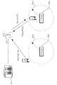
도 2는 일 실시예에 따른 수요반응 서버가 수요반응지령을 전송하는 단말을 나타내는 도면이다.2 is a diagram illustrating a terminal for transmitting a demand response command by a demand response server according to an embodiment.
도 2를 참조하면, 서버(110)는 제1 단말(120a)에 대하여만 수요반응지령을 전송하고 제2 단말(120b)에 대하여는 수요반응지령을 전송하지 않고 있다.Referring to FIG. 2, the
좀더 구체적으로 살펴보면, DR부하1(130a)을 중심으로 주변에 제1 부하관리범위(170a)가 설정되어 있고, DR부하2(130b)를 중심으로 주변에 제2 부하관리범위(170b)가 설정되어 있다. 여기서 제1 부하관리범위(170a)와 제2 부하관리범위(170b)는 같은 값일 수 있으나 다른 값일 수도 있다.More specifically, the first
제1 단말(120a)은 DR부하1(130a)의 제1 부하관리범위(170a) 내에 위치하고 있다. 이에 반해, 제2 단말(120b)은 DR부하2(130b)의 제2 부하관리범위(170b) 밖에 위치하고 있다. 이에 대하여, 서버(110)는 부하의 부하관리범위 내에 위치하고 있는 단말에 대하여만 수요반응지령을 전송할 수 있다.The
부하관리범위는 수요반응지령에 대하여 부하를 제어할 수 있는 범위를 나타내는 것으로 서버(110)에 의해 일방적으로 설정될 수 있고, 또한, 개별 부하의 특성에 따라 각각의 부하의 특성에 맞는 부하관리범위 값이 설정될 수도 있다.The load management range can be unilaterally set by the
도 2를 참조하면, 단말들(120a, 120b)은 자신의 위치정보를 무선통신기지국(160)을 통해 서버(110)로 전송하고 서버(110)는 이러한 단말들(120a, 120b)의 위치정보를 바탕으로 각각의 단말이 부하관리범위 이내에 있는지 판단하고 부하관리범위 이내에 있는 단말(120a)로만 수요반응지령을 전송한다.
2, the
도 3은 일 실시예에 따른 수요반응 서버의 내부 블록도이다.3 is an internal block diagram of a demand response server according to an embodiment.
서버(110)는 수요반응 제어를 수행하기 위한 정보를 저장하는 저장부(310), 주변 장치들로부터 정보를 수신하는 수신부(320), 수요반응 제어를 수행하는 제어부(330) 및 주변 장치들로 정보를 전송하는 송신부(340) 등을 포함할 수 있다.The
구체적인 실시예로서 서버(110)는 수요반응에 참여하는 부하들의 부하위치정보를 포함하는 부하정보를 저장하고, 각각의 부하를 관리하는 수요반응 참여자들의 단말정보를 관리되는 부하와 연계하여 저장하는 저장부(310), 각각의 수요반응 참여자들의 단말로부터 단말위치정보를 수신하는 수신부(320), 부하위치정보 및 단말위치정보를 비교하고, 연계된 부하의 부하위치로부터 부하관리범위 이내에 위치하는 단말들을 지령전송단말들로 결정하는 제어부(330), 지령전송단말들로만 수요반응지령을 전송하는 송신부(340) 등을 포함할 수 있다.
As a concrete example, the
서버(110)는 단말로부터 단말위치정보를 수신하는데, 이때, 단말은 무선통신기지국들로부터 수신되는 신호를 측정하여 단말위치를 추정할 수 있다.The
도 4는 일 실시예에 따른 수요반응 단말이 단말위치를 추정하는 방법을 설명하기 위한 도면이다.4 is a diagram for explaining a method of estimating a terminal location by a demand response terminal according to an embodiment.
단말(120)은 셀커버리지(도 4에서, 410a, 410b, 410c) 내에서 해당 셀커버리지를 형성하는 무선통신기지국(도 4에서, 160a, 160b, 160c)과 신호를 주고 받으면서 통신한다. 도 4를 참조할 때, 단말(120)은 참조번호 160a의 무선통신기지국의 셀커버리지(410a) 내에서 해당 무선통신기지국(160a)과 신호를 주고 받는다. 이때, 단말(120)은 신호를 주고 받는 무선통신기지국(160a)으로부터 해당 무선통신기지국(160a)에 대한 아이디 값을 받게 된다. 이러한 아이디 값은 무선통신기지국을 구분하는 고유한 값으로 이러한 아이디 값을 통해 단말(120)은 해당 아이디 값을 가지는 무선통신기지국의 셀커버리지에 위치하고 있다고 판단하게 된다.The terminal 120 communicates with a wireless communication base station (160a, 160b, and 160c in FIG. 4) that forms the corresponding cell coverage within the cell coverage (410a, 410b, and 410c in FIG. Referring to FIG. 4, a
단말(120)은 통신하고 있는 무선통신기지국의 아이디를 단말위치정보로서 서버(110)로 송신할 수 있다. 이때, 서버(110)는 해당 아이디를 가지는 무선통신기지국의 위치정보를 확인하여 단말위치를 파악할 수 있다.The terminal 120 can transmit the ID of the communicating radio base station to the
단말위치를 확인하는 다른 방법으로서 단말(120)은 적어도 셋 이상의 무선통신기지국들로부터 수신되는 신호를 측정하여 단말위치를 추정할 수 있다. 도 4를 참조할 때, 단말(120)은 세 개의 무선통신기지국들(160a, 160b, 160c)로부터 신호를 수신하고 있다. 이때, 단말(120)은 각각의 무선통신기지국들(160a, 160b, 160c)로부터 수신되는 신호의 세기 혹은 신호의 도착시간을 측정하여 각각의 무선통신기지국까지의 거리를 추정할 수 있다. 예를들어, 신호의 세기는 통신방법에 따라 거리의 제곱, 세제곱 등에 반비례하면서 작아질 수 있는데, 이러한 원리를 이용하여 측정된 신호의 세기를 통해 해당 신호를 전송한 무선통신기지국까지의 거리를 추정할 수 있다. 또한, 시간상으로 동기화된 신호를 서로 다른 두 무선통신기지국에서 송신할 때, 신호가 도착하는 시간의 차이를 통해 두 무선통신기지국의 상대적인 거리 차이를 측정할 수 있다.As another method of confirming the terminal location, the terminal 120 can estimate a terminal location by measuring signals received from at least three wireless communication base stations. Referring to FIG. 4, the terminal 120 is receiving signals from three wireless
이렇게 적어도 셋 이상의 무선통신기지국들로부터 수신되는 신호를 측정하여 각각의 무선통신기지국으로부터 단말까지의 거리를 계산하고, 이러한 거리를 삼각측량법에 대입함으로써 단말(120)은 단말의 위치를 추정해 낼 수 있다.In this way, by measuring the signal received from at least three or more radio communication base stations, calculating the distance from each radio communication base station to the terminal, and assigning this distance to the triangulation method, the terminal 120 can estimate the position of the terminal have.
단말(120)은 GPS(global positioning system) 신호를 이용하여 단말위치를 추정할 수 있다.The terminal 120 can estimate the terminal position using a global positioning system (GPS) signal.
단말(120)이 단말위치를 추정하기 위해 사용할 수 있는 전술한 세 가지 방법은 서로 경쟁적이기 보다는 보완적이다. 단말(120)은 필요에 따라 세 가지 방법 중 하나의 방법으로 단말위치를 추정할 수 있지만 또한, 경우에 따라서는 서로 다른 두 가지 이상의 방법을 함께 사용하면서 단말위치에 대한 추정값의 정확도를 향상시킬 수 있다.
The three methods that the terminal 120 may use to estimate the terminal location are complementary rather than competitive. The terminal 120 can estimate the terminal position using one of three methods as necessary. However, in some cases, the terminal 120 can improve the accuracy of the estimated value of the terminal location by using two or more different methods together have.
저장부(310)는 수요반응 제어를 수행하기 위한 제반 정보를 저장할 수 있다.The
도 5는 일 실시예에 따른 수요반응 서버에 저장되는 수요반응 참여자 데이터베이스의 일 예시 구성도이다.5 is a block diagram of an example of a demand response participant database stored in a demand response server according to an embodiment.
도 5를 참조하면, 저장부(310)는 참여자 정보 테이블(510)을 저장할 수 있다. 이러한 참여자 정보 테이블(510)에는 수요반응 참여자에 대한 정보가 저장될 수 있다. 예를들어, 참여자의 이름, 주소 등의 인적사항이 저장될 수 있다. 또한, 참여자 정보 테이블(510)에는 참여자의 단말에 대한 정보가 저장될 수 있다. 이러한 참여자의 단말에 대한 정보는 서버(110)가 수요반응지령을 전송하는데 사용된다.Referring to FIG. 5, the
참여자 정보 테이블(510)에는 참여자의 단말정보가 참여자가 관리하는 부하정보와 연계하여 저장될 수 있다. 도 4를 참조하면, 참여자의 단말정보로서 통신 ID(512)가 저장되고 있다. 통신 ID(512)는 무선통신시스템을 이용하여 정보를 송수신할 수 있는 아이디로 통상적인 전화번호가 이러한 통신 ID에 해당될 수 있다.In the participant information table 510, the terminal information of the participant can be stored in association with the load information managed by the participant. Referring to FIG. 4, a
참여자 정보 테이블(510)에 저장되는 참여자의 단말정보는 부하정보(514)와 연계되어 저장되는데, 부하정보(514)는 별도의 부하정보테이블(520)을 통해 하위정보를 더 포함할 수 있다.The participant terminal information stored in the participant information table 510 is stored in association with the
부하정보테이블(520)은 부하가 사용할 수 있는 총부하량정보(522)를 포함할 수 있다. 이러한 총부하량정보(522)는 정격전력에 해당되는 값으로 부하가 정격으로 가동될 때, 사용하는 전력량이다.The load information table 520 may include
부하정보테이블(520)은 부하가 수요반응에서 감축가능한 부하량정보(524)를 포함할 수 있다. 제어부(330)는 각각의 부하에 대한 수요반응 감축가능 부하량정보(524)를 이용하여 수요반응 가능자원량을 예측할 수 있다. 예를들어, 제어부(330)는 부하위치정보와 단말위치정보를 비교하여 부하위치로부터 부하관리범위이내에 위치하는 단말들을 지령전송단말로 결정하게 된다. 이때, 제어부(330)는 지령전송단말들에 대해 저장된 이러한 수요반응 감축가능 부하량정보(524)를 이용하여 수요반응 가능자원량을 예측하게 된다.The load information table 520 may include
부하정보테이블(520)은 부하가 수요반응에 참여할 수 있는 시간에 대한 정보(참여 가능 시간 정보, 526)를 포함할 수 있다. 수요반응 참여자의 행동 유형에 따라 부하를 제어하지 못하는 시간대가 존재할 수 있다. 예를들어, 취침시간에 해당되는 야간시간대, 공장가동시간대 혹은 참여자가 방해를 받고 싶지 않아하는 시간대에서는 수요반응 참여자가 수요반응지령을 수신하여도 수요반응에 참가하지 않을 수 있다. 제어부(330)는 부하와 연계된 단말에 대하여 해당 부하에 대한 참여 가능 시간 정보(526)를 확인하고, 수요반응 서비스에 참여할 수 없는 시간대에는 수요반응지령을 전송하지 않을 수 있다.The load information table 520 may include information on the time when the load can participate in the demand reaction (available time information, 526). Depending on the type of behavior of the demand response participants, there may be times when the load can not be controlled. For example, in a night time zone corresponding to bedtime, a factory operation time zone, or a time zone in which a participant does not want to be disturbed, a demand response participant may not participate in a demand response even if it receives a demand response command. The
부하정보테이블(520)은 부하위치정보(528)를 저장한다. 부하위치정보는 부하의 지리상 위치에 대한 정보 뿐만 아니라 부하관리범위에 대한 정보를 더 포함할 수 있다. 이러한 부하관리범위는 부하의 특성에 따라 달라질 수 있다. 예를들어, 빌딩에 포함되어 있는 부하는 빌딩 내 어느 곳에서나 제어가 가능하기 때문에 부하관리범위가 넓다. 이에 반해, 개별주택에 포함되어 있는 부하는 해당 주택이내에서만 제어가 가능하기 때문에 부하관리범위가 좁다.The load information table 520 stores load
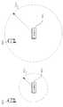
도 6은 두 부하에 대하여 부하관리범위가 다르게 제어되는 것을 설명하기 위한 도면이다.6 is a diagram for explaining that the load management range is controlled differently for two loads.
도 6을 참조하면, 부하(130a, 130b)와 단말(120a, 120b)의 거리가 실질적으로 동일하다. 그런데, DR부하1(130a)의 제1 부하관리범위(170a)는 DR부하2(130b)의 제2 부하관리범위(170b) 보다 크다. 이에 따라, 제1 단말(120a)은 제1 부하관리범위(170a) 내에 위치하게 되고, 제2 단말(120b)은 제2 부하관리범위(170b) 밖에 위치하게 된다. 그리고, 제어부(330)는 부하관리범위 내에 위치하는 제1 단말(120a)로만 수요반응지령을 전송하게 된다. 이렇게 제어부(330)는 부하들의 부하관리범위를 서로 다르게 제어할 수 있다.Referring to FIG. 6, the distances between the
부하관리범위는 부하의 특성에 따라 다르게 설정될 수 있으나, 부하의 특성이 파악되지 않는 상황에서는 반복되는 변경 제어를 통해 설정될 수 있다.The load management range can be set differently depending on the characteristics of the load, but it can be set through repeated change control in a situation where the characteristics of the load are not known.
도 7은 부하관리범위가 변경 제어되는 것을 나타내는 도면이다.7 is a diagram showing that the load management range is changed and controlled.
제어부(330)는 수요반응지령을 발송하고 발송된 단말(120)과 연계된 부하(130)의 미터를 통해 부하사용량정보를 획득할 수 있다. 이렇게 미터로부터 부하사용량정보를 획득하게 되면, 제어부(330)는 수요반응지령을 전송한 지령전송단말들과 연계된 부하가 수요반응에 참여하였는지 여부를 파악할 수 있게 된다.The
제어부(330)는 수요반응 참여여부가 미참여로 파악되는 부하(130)의 부하관리범위(170)가 작아지도록 제어할 수 있다. 또한 같은 맥락에서 제어부(330)는 수요반응 참여여부가 참여로 파악된 부하의 부하관리범위가 커지도록 제어할 수 있다.The
제어부(330)는 수요반응 참여여부에 대한 통계를 통해 이러한 부하관리범위 변경 제어를 수행할 수 있다. 적어도 둘 이상의 수요반응 참여여부에 대한 통계처리를 통해 단말위치에 따른 수요반응 참여여부에 대한 관계도를 파악하고 이러한 관계도에 따라 부하의 부하관리범위를 변경할 수 있다.
The
도 8은 일 실시예에 따른 수요반응 서버의 제어방법에 대한 흐름도이다.8 is a flowchart illustrating a method of controlling a demand response server according to an embodiment of the present invention.
도 8을 참조하여 설명하는 제어방법은 도 1 내지 도 7을 참조하여 설명한 서버(110)에 의해 모두 수행될 수 있는 것이다. 또한, 서버(110)에 대한 실시예로서 설명한 내용들은 또한, 제어방법적으로 아래에서 설명하는 실시예들과 결합하여 다른 실시예를 구성할 수 있다.The control method described with reference to FIG. 8 can be all performed by the
도 8을 참조하면, 서버(110)는 계통의 전력수급상태를 파악하고 전력수급상태에 따라 수요반응지령을 전송한다.Referring to FIG. 8, the
여기에서, 서버(110)는 수요반응에 참여하는 부하들의 부하위치정보를 포함하는 부하정보를 저장하고, 각각의 부하를 관리하는 수요반응 참여자들의 단말정보를 관리되는 부하와 연계하여 저장한다(S810). 이때, 저장되는 부하정보는 부하의 수요반응에서의 감축가능한 부하량정보를 더 포함할 수 있다.Here, the
서버(110)는 각각의 수요반응 참여자들의 단말로부터 단말위치정보를 수신한다(S820).The
그리고, 서버(110)는 부하위치정보 및 단말위치정보를 비교하고, 연계된 부하의 부하위치로부터 부하관리범위 이내에 위치하는 단말들을 지령전송단말들로 결정하고(S820), 이러한 지령전송단말들로만 수요반응지령을 전송한다(S840).The
한편, S820 단계에서, 서버(110)는 지령전송단말들과 연계된 부하들의 감축가능한 부하량정보를 이용하여 수요반응 가능자원량을 예측할 수 있고, 적어도 두 부하의 부하관리범위를 서로 다르게 제어할 수 있다. 또한, S820 단계에서, 서버(110)는 각각의 부하와 연계된 미터(meter)로부터 획득된 부하사용량정보를 통해 지령전송단말들과 연계된 부하의 수요반응 참여여부를 파악하고, 수요반응 참여여부가 미참여로 파악된 부하의 부하관리범위가 작아지도록 제어하거나 수요반응 참여여부가 참여로 파악된 부하의 부하관리범위가 커지도록 제어할 수 있다.
On the other hand, in step S820, the
도 9는 일 실시예에 따른 수요반응 단말의 내부 블록도이다.9 is an internal block diagram of a demand response terminal according to an embodiment.
도 9에 도시된 단말(120)은 도 1에 도시된 제1 단말(120a) 혹은 제2 단말(120b)로 계통의 전력수급상태를 파악하고 전력수급상태에 따라 수요반응지령을 전송하는 수요반응 서버(110)로부터 수요반응지령을 수신하는 단말이다.The terminal 120 shown in FIG. 9 checks the power supply / demand status of the system to the
도 9를 참조하면, 단말(120)은 적어도 셋 이상의 무선통신기지국들로부터 수신되는 신호를 측정하여 단말위치를 추정하는 제어부(910), 단말위치를 포함하는 단말위치정보를 무선통신기지국들 중 적어도 하나의 무선통신기지국과의 무선 통신 자원을 통해 수요반응 서버로 전송하는 송신부(920) 및 연계된 부하의 위치로부터 부하관리범위 이내에 있을 때, 수요반응 서버로부터 수요반응지령을 수신하는 수신부(930) 등을 포함할 수 있다.9, a terminal 120 includes a
한편, 제어부(910)는 삼각측량을 이용하여 단말위치를 추정할 수 있다.
On the other hand, the
도 10은 일 실시예에 따른 수요반응 단말의 제어방법에 대한 흐름도이다.10 is a flowchart illustrating a method of controlling a demand response terminal according to an embodiment of the present invention.
도 10의 제어방법을 수행하는 단말은 도 9에 도시된 단말(120)로서 전술한 바와 같이 도 1에 도시된 제1 단말(120a) 혹은 제2 단말(120b)로서 계통의 전력수급상태를 파악하고 전력수급상태에 따라 수요반응지령을 전송하는 수요반응 서버(110)로부터 수요반응지령을 수신하는 단말이다.The terminal performing the control method of FIG. 10 is a terminal 120 shown in FIG. 9, and as described above, as the
도 10을 참조하면, 단말(120)은 적어도 셋 이상의 무선통신기지국들로부터 수신되는 신호를 측정하여 단말위치를 추정하고(S1010), 단말위치를 포함하는 단말위치정보를 무선통신기지국들 중 적어도 하나의 무선통신기지국과의 무선 통신 자원을 통해 수요반응 서버로 전송한다(S1020). 그리고, 단말(120)은 연계된 부하의 위치로부터 부하관리범위 이내에 있을 때, 수요반응 서버로부터 수요반응지령을 수신한다(S1030).10, the terminal 120 measures a signal received from at least three wireless communication base stations to estimate the terminal position (S1010), and transmits terminal position information including the terminal position to at least one of the wireless communication base stations To the demand response server through wireless communication resources with the wireless communication base station in step S1020. Then, when the terminal 120 is within the load management range from the position of the associated load, it receives a demand reaction command from the demand response server (S1030).
한편, S1010 단계에서, 단말(120)은 삼각측량을 이용하여 단말위치를 추정할 수 있다.
On the other hand, in step S1010, the terminal 120 can estimate the terminal position using triangulation.
한편, 추가적인 실시예로서, 서버(110)는 참여자(단말)에게 수요반응지령을 전송하고 참여자의 수요반응 참여여부를 확인하여 수요반응 참여여부 통계에 따라 참여자의 부하관리범위를 설정(제어부(330)에 의해 설정될 수 있음)할 수 있다. 예를 들어, A라는 참여자는 부하로부터의 거리가 20m에 해당되는 위치에 있을 때에도 계속해서 수요반응에 참여하고 있다면 A의 부하관리범위는 20m 이상으로 설정될 수 있다. 이에 반해, B라는 참여자는 부하로부터 10m 이상 벗어나는 위치에 있을 때에는 수요반응에 참여하지 않는다면, B의 부하관리범위는 10m 이내로 설정될 수 있다.Meanwhile, as a further embodiment, the
이러한 추가적인 실시예와 관련하여, 서버(110)는 처음에는 전체 참여자에게 수요반응지령을 발송하고 이에 대한 참여자의 참여여부를 확인하는 과정을 다수 실시할 수 있다. 그후, 참여자의 부하관리범위를 확정하고 이에 따라 전술한 실시예들을 실시할 수 있다.In connection with this additional embodiment, the
경우에 따라서는 부하관리범위가 0으로 설정될 수도 있다. 이는 참여자가 사실상 어떠한 지령에 대해서는 참여하지 않는다는 것을 의미한다.
In some cases, the load management range may be set to zero. This means that the participant does not participate in virtually any command.
또다른 추가 실시예로서, 부하관리범위 이외에 참여도라는 항목을 추가하여 참여도에 따라 수요반응지령을 다르게 전송할 수도 있다. 참여도에 따라 부하관리범위를 수시로 변경하게 되면 제어가 불안정해 질 수 있는데, 서버(110)는 이렇게 참여도에 따라 부하관리범위를 수시로 변경하지 않고 참여도를 별도의 항목으로 관리하여 참여도가 낮은 참여자에게는 수요반응지령을 전송하는 횟수를 줄임으로써 참여자의 피로도를 낮출 수 있다.
As another additional embodiment, it is possible to additionally add the item "participation degree" in addition to the load management scope to transmit the demand response command differently according to the degree of participation. If the load management range is changed from time to time according to the degree of participation, the control may become unstable. The
이상에서 기재된 "포함하다", "구성하다" 또는 "가지다" 등의 용어는, 특별히 반대되는 기재가 없는 한, 해당 구성 요소가 내재될 수 있음을 의미하는 것이므로, 다른 구성 요소를 제외하는 것이 아니라 다른 구성 요소를 더 포함할 수 있는 것으로 해석되어야 한다. 기술적이거나 과학적인 용어를 포함한 모든 용어들은, 다르게 정의되지 않는 한, 본 발명이 속하는 기술 분야에서 통상의 지식을 가진 자에 의해 일반적으로 이해되는 것과 동일한 의미를 가진다. 사전에 정의된 용어와 같이 일반적으로 사용되는 용어들은 관련 기술의 문맥 상의 의미와 일치하는 것으로 해석되어야 하며, 본 발명에서 명백하게 정의하지 않는 한, 이상적이거나 과도하게 형식적인 의미로 해석되지 않는다.It is to be understood that the terms "comprises", "comprising", or "having" as used in the foregoing description mean that the constituent element can be implanted unless specifically stated to the contrary, But should be construed as further including other elements. All terms, including technical and scientific terms, have the same meaning as commonly understood by one of ordinary skill in the art to which this invention belongs, unless otherwise defined. Commonly used terms, such as predefined terms, should be interpreted to be consistent with the contextual meanings of the related art, and are not to be construed as ideal or overly formal, unless expressly defined to the contrary.
이상의 설명은 본 발명의 기술 사상을 예시적으로 설명한 것에 불과한 것으로서, 본 발명이 속하는 기술 분야에서 통상의 지식을 가진 자라면 본 발명의 본질적인 특성에서 벗어나지 않는 범위에서 다양한 수정 및 변형이 가능할 것이다. 따라서, 본 발명에 개시된 실시예들은 본 발명의 기술 사상을 한정하기 위한 것이 아니라 설명하기 위한 것이고, 이러한 실시예에 의하여 본 발명의 기술 사상의 범위가 한정되는 것은 아니다. 본 발명의 보호 범위는 아래의 청구범위에 의하여 해석되어야 하며, 그와 동등한 범위 내에 있는 모든 기술 사상은 본 발명의 권리범위에 포함되는 것으로 해석되어야 할 것이다.The foregoing description is merely illustrative of the technical idea of the present invention, and various changes and modifications may be made by those skilled in the art without departing from the essential characteristics of the present invention. Therefore, the embodiments disclosed in the present invention are intended to illustrate rather than limit the scope of the present invention, and the scope of the technical idea of the present invention is not limited by these embodiments. The scope of protection of the present invention should be construed according to the following claims, and all technical ideas within the scope of equivalents should be construed as falling within the scope of the present invention.
Claims (15)
Translated fromKorean부하들의 위치를 나타내는 부하위치정보, 상기 수요반응 참여자들이 상기 부하들을 제어할 수 있는 위치 범위를 나타내는 부하관리범위, 수요반응시 감축가능한 부하량정보 및 수요반응에 참여할 수 있는 시간에 대한 참여 가능 시간 정보를 포함하는 부하정보 및 각각의 부하를 관리하는 상기 수요반응 참여자들의 상기 단말들에 대한 단말정보를 상기 부하들과 연계하여 저장하는 저장부;
상기 단말들로부터 단말위치정보를 수신하는 수신부;
상기 부하위치정보 및 상기 단말위치정보의 비교에서 단말위치가 부하위치로부터 부하관리범위 이내에 위치하고 참여 가능 시간 정보에서 수요반응에 참여할 수 있는 시간대에 해당되는 단말들을 지령전송단말들로 결정하고,
상기 지령전송단말들에 대한 상기 감축가능한 부하량정보를 이용하여 수요반응 가능자원량을 계산하며,
각각의 부하와 연계된 미터(meter)로부터 획득된 부하사용량정보를 통해 상기 지령전송단말들과 연계된 부하의 수요반응 참여여부를 파악하고 상기 수요반응 참여여부에 대한 통계처리를 통해 단말위치에 따른 수요반응 참여여부의 관계도를 파악하며 상기 관계도에 따라 부하관리범위를 설정하는 제어부; 및
상기 지령전송단말들로만 상기 수요반응지령을 전송하는 송신부
를 포함하는 수요반응 서버.
A server for receiving a demand response command to wireless communication terminals of demand response participants who have joined the demand response service according to the power supply status,
A load management range indicating the position range in which the demand reaction participants can control the loads, a load amount information capable of reducing in a demand response, and a time available for participating in a demand response And load information including the load information and terminal information for the terminals of the demand reaction participants managing each load in association with the loads and storing the load information;
A receiver for receiving terminal location information from the terminals;
Determining the terminals corresponding to the time zones in which the terminal position is within the load management range from the load position and participating in the demand response in the available time information in the comparison of the load position information and the terminal position information,
A demand-responsive resource amount is calculated using the reducible load amount information for the command transmission terminals,
The load demand information obtained from the meter associated with each load is used to determine whether or not the load reaction associated with the command transmission terminals is participated in the demand reaction, A control unit for determining a relationship diagram of demand reaction participation and setting a load management range according to the relationship diagram; And
A transmitter for transmitting the demand response command only to the command transmitting terminals
A demand response server comprising:
상기 수신부는,
적어도 셋 이상의 무선통신기지국들로부터 수신되는 신호를 측정하여 단말위치를 추정하고 추정된 상기 단말위치를 포함하는 단말위치정보를 상기 각각의 수요반응 참여자들의 단말로부터 수신하는 것을 특징으로 하는 수요반응 서버.
The method according to claim 1,
The receiver may further comprise:
And estimating a terminal location by measuring a signal received from at least three or more wireless communication base stations and receiving terminal location information including the estimated terminal location from the terminal of each demand response participant.
상기 제어부는,
적어도 두 부하의 부하관리범위를 서로 다르게 제어하는 것을 특징으로 하는 수요반응 서버.
The method according to claim 1,
Wherein,
Wherein the load management range of at least two loads is controlled differently.
상기 제어부는,
상기 수요반응 참여여부가 미참여로 파악된 부하의 부하관리범위가 작아지도록 제어하거나 상기 수요반응 참여여부가 참여로 파악된 부하의 부하관리범위가 커지도록 제어하는 것을 특징으로 하는 수요반응 서버.
The method according to claim 1,
Wherein,
Wherein the control unit controls to control the load management range of the load detected as the non-participation in the demand reaction to be small, or to control the load management range of the load in which the demand reaction participation is determined to participate.
부하들의 위치를 나타내는 부하위치정보, 상기 수요반응 참여자들이 상기 부하들을 제어할 수 있는 위치 범위를 나타내는 부하관리범위, 수요반응시 감축가능한 부하량정보 및 수요반응에 참여할 수 있는 시간에 대한 참여 가능 시간 정보를 포함하는 부하정보 및 각각의 부하를 관리하는 상기 수요반응 참여자들의 상기 단말들에 대한 단말정보를 상기 부하들과 연계하여 저장하는 저장단계;
상기 단말들로부터 단말위치정보를 수신하는 수신단계;
상기 부하위치정보 및 상기 단말위치정보의 비교에서 단말위치가 부하위치로부터 부하관리범위 이내에 위치하고 참여 가능 시간 정보에서 수요반응에 참여할 수 있는 시간대에 해당되는 단말들을 지령전송단말들로 결정하고,
상기 지령전송단말들에 대한 상기 감축가능한 부하량정보를 이용하여 수요반응 가능자원량을 계산하며,
각각의 부하와 연계된 미터(meter)로부터 획득된 부하사용량정보를 통해 상기 지령전송단말들과 연계된 부하의 수요반응 참여여부를 파악하고 상기 수요반응 참여여부에 대한 통계처리를 통해 단말위치에 따른 수요반응 참여여부의 관계도를 파악하며 상기 관계도에 따라 부하관리범위를 설정하는 제어단계; 및
상기 지령전송단말들로만 상기 수요반응지령을 전송하는 송신단계
를 포함하는 수요반응 제어방법.
A method of controlling a server that grasps a power supply state of a system and transmits a demand response command to wireless communication terminals of demand reaction participants who subscribe to a demand response service according to the power supply state,
A load management range indicating the position range in which the demand reaction participants can control the loads, a load amount information capable of reducing in a demand response, and a time available for participating in a demand response Storing the load information including the load information and terminal information about the terminals of the demand reaction participants managing each load in association with the loads;
Receiving terminal position information from the terminals;
Determining the terminals corresponding to the time zones in which the terminal position is within the load management range from the load position and participating in the demand response in the available time information in the comparison of the load position information and the terminal position information,
A demand-responsive resource amount is calculated using the reducible load amount information for the command transmission terminals,
The load demand information obtained from the meter associated with each load is used to determine whether or not the load reaction associated with the command transmission terminals participates in the demand reaction, A control step of determining a relationship degree of whether or not a demand reaction is participated and setting a load management range according to the relationship diagram; And
A transmission step of transmitting the demand response command only to the command transmission terminals
And a demand reaction control method.
상기 제어단계에서,
적어도 두 부하의 부하관리범위를 서로 다르게 제어하는 것을 특징으로 하는 수요반응 제어방법.
9. The method of claim 8,
In the control step,
Wherein a load management range of at least two loads is controlled differently.
상기 제어단계에서,
상기 수요반응 참여여부가 미참여로 파악된 부하의 부하관리범위가 작아지도록 제어하거나 상기 수요반응 참여여부가 참여로 파악된 부하의 부하관리범위가 커지도록 제어하는 것을 특징으로 하는 수요반응 제어방법.
9. The method of claim 8,
In the control step,
Wherein the control unit controls the load control range of the load detected as the non-attendance of the demand reaction to be small or controls the load management range of the load that is determined to be participating in the demand response to be large.
Priority Applications (1)
| Application Number | Priority Date | Filing Date | Title |
|---|---|---|---|
| KR1020130120478AKR101579847B1 (en) | 2013-10-10 | 2013-10-10 | Demand response server, terminal and control method |
Applications Claiming Priority (1)
| Application Number | Priority Date | Filing Date | Title |
|---|---|---|---|
| KR1020130120478AKR101579847B1 (en) | 2013-10-10 | 2013-10-10 | Demand response server, terminal and control method |
Publications (2)
| Publication Number | Publication Date |
|---|---|
| KR20150041921A KR20150041921A (en) | 2015-04-20 |
| KR101579847B1true KR101579847B1 (en) | 2015-12-23 |
Family
ID=53035211
Family Applications (1)
| Application Number | Title | Priority Date | Filing Date |
|---|---|---|---|
| KR1020130120478AActiveKR101579847B1 (en) | 2013-10-10 | 2013-10-10 | Demand response server, terminal and control method |
Country Status (1)
| Country | Link |
|---|---|
| KR (1) | KR101579847B1 (en) |
Families Citing this family (3)
| Publication number | Priority date | Publication date | Assignee | Title |
|---|---|---|---|---|
| KR101985532B1 (en)* | 2015-07-08 | 2019-06-03 | 주식회사 케이티 | Method for predicting issue of demand response, server and computer program |
| KR102433167B1 (en)* | 2017-09-29 | 2022-08-18 | 한국전력공사 | V2x-ess associated system and method for considering charge and discharge priority of building and grid |
| KR102546584B1 (en)* | 2017-10-12 | 2023-06-22 | 한국전자기술연구원 | System and method for providing DR guide to customer |
Family Cites Families (4)
| Publication number | Priority date | Publication date | Assignee | Title |
|---|---|---|---|---|
| KR100421311B1 (en)* | 2001-06-21 | 2004-03-09 | 에스케이 텔레콤주식회사 | Apparatus and method for managing location area for mobile communication terminals |
| US7715951B2 (en)* | 2007-08-28 | 2010-05-11 | Consert, Inc. | System and method for managing consumption of power supplied by an electric utility |
| KR100953403B1 (en)* | 2008-08-06 | 2010-04-19 | 중앙대학교 산학협력단 | Real time intelligent autonomous load management apparatus and method |
| KR101164321B1 (en)* | 2009-12-18 | 2012-07-09 | 에스케이 텔레콤주식회사 | Demand response system and method using a smart portal |
- 2013
- 2013-10-10KRKR1020130120478Apatent/KR101579847B1/enactiveActive
Also Published As
| Publication number | Publication date |
|---|---|
| KR20150041921A (en) | 2015-04-20 |
Similar Documents
| Publication | Publication Date | Title |
|---|---|---|
| US20120021689A1 (en) | Signaling method and device for mitigating interference in m2m communication system | |
| US20170086143A1 (en) | Multi-factor provisioning of wireless devices | |
| JPWO2013128903A1 (en) | Handset of power management system and power management system | |
| CN104113832A (en) | Power control method and power control system used for direct communication of terminal, and base station | |
| KR101579847B1 (en) | Demand response server, terminal and control method | |
| CN104765349A (en) | Method for managing smart home equipment, server and center control equipment | |
| WO2014132643A1 (en) | Transmitting device and transmitting method | |
| CN103684937A (en) | A network topological structure in an intelligent household communication system and an establishment method thereof | |
| JP2014086990A (en) | Distance measurement method between mobile terminals, method for implementing network using the same, and mobile terminal therefor | |
| KR20190038712A (en) | ENERGY MANAGEMENT IoT AND CLOUD BASED NETWORK RELAY DEVICE OF SAMRT HOME PLATFORM AND METHOD THEREOF | |
| WO2015087500A1 (en) | Meter reader and communication system | |
| KR101611472B1 (en) | Location based electric power management method and system thereof | |
| JP2014055798A (en) | Display unit, method and program | |
| CN106455129A (en) | Control method and control device for connection of light source and access point, and wireless local area network | |
| JP2013192419A (en) | Electricity consumption control system | |
| KR20170121627A (en) | Remote inspection system and communication method of the same | |
| KR101665019B1 (en) | Electric power management method | |
| WO2016095463A1 (en) | Cell selection method, device, and system | |
| KR101646747B1 (en) | Electric power management system | |
| JP6169830B2 (en) | COMMUNICATION PROCESS LIMITATION METHOD, COMMUNICATION DEVICE, AND AUXILIARY DEVICE | |
| JP6365814B2 (en) | Meter reading device, communication method, management device, and communication system | |
| KR20140028710A (en) | Power line communication apparatus, access point equipment and method for managing quality of communication service | |
| EP3337221A1 (en) | Access node, controller for access node, and method for optimizing network deployment | |
| WO2016095424A1 (en) | Terminal access method, apparatus and system | |
| JP6396693B2 (en) | Information transmission / reception system, information communication apparatus, management apparatus, information transmission / reception method, information communication apparatus program, and management apparatus program |
Legal Events
| Date | Code | Title | Description |
|---|---|---|---|
| A201 | Request for examination | ||
| PA0109 | Patent application | Patent event code:PA01091R01D Comment text:Patent Application Patent event date:20131010 | |
| PA0201 | Request for examination | ||
| E902 | Notification of reason for refusal | ||
| PE0902 | Notice of grounds for rejection | Comment text:Notification of reason for refusal Patent event date:20150327 Patent event code:PE09021S01D | |
| PG1501 | Laying open of application | ||
| PE0701 | Decision of registration | Patent event code:PE07011S01D Comment text:Decision to Grant Registration Patent event date:20151215 | |
| GRNT | Written decision to grant | ||
| PR0701 | Registration of establishment | Comment text:Registration of Establishment Patent event date:20151217 Patent event code:PR07011E01D | |
| PR1002 | Payment of registration fee | Payment date:20151218 End annual number:3 Start annual number:1 | |
| PG1601 | Publication of registration | ||
| FPAY | Annual fee payment | Payment date:20180918 Year of fee payment:4 | |
| PR1001 | Payment of annual fee | Payment date:20180918 Start annual number:4 End annual number:4 | |
| FPAY | Annual fee payment | Payment date:20190909 Year of fee payment:5 | |
| PR1001 | Payment of annual fee | Payment date:20190909 Start annual number:5 End annual number:5 | |
| PR1001 | Payment of annual fee | Payment date:20200911 Start annual number:6 End annual number:6 | |
| PR1001 | Payment of annual fee | Payment date:20210924 Start annual number:7 End annual number:7 | |
| PR1001 | Payment of annual fee | Payment date:20220926 Start annual number:8 End annual number:8 | |
| PR1001 | Payment of annual fee | Payment date:20240911 Start annual number:10 End annual number:10 |