KR101575313B1 - Curved display device and display method using the same - Google Patents
Curved display device and display method using the sameDownload PDFInfo
- Publication number
- KR101575313B1 KR101575313B1KR1020130159595AKR20130159595AKR101575313B1KR 101575313 B1KR101575313 B1KR 101575313B1KR 1020130159595 AKR1020130159595 AKR 1020130159595AKR 20130159595 AKR20130159595 AKR 20130159595AKR 101575313 B1KR101575313 B1KR 101575313B1
- Authority
- KR
- South Korea
- Prior art keywords
- light
- output voltage
- projected
- abnormal position
- dot
- Prior art date
- Legal status (The legal status is an assumption and is not a legal conclusion. Google has not performed a legal analysis and makes no representation as to the accuracy of the status listed.)
- Active
Links
- 238000000034methodMethods0.000titleclaimsdescription19
- 230000002159abnormal effectEffects0.000claimsabstractdescription24
- 230000001360synchronised effectEffects0.000claims2
- 230000003287optical effectEffects0.000description9
- 238000010586diagramMethods0.000description4
- 230000000694effectsEffects0.000description2
- 238000007792additionMethods0.000description1
- 238000012217deletionMethods0.000description1
- 230000037430deletionEffects0.000description1
- 230000007704transitionEffects0.000description1
Images


Classifications
- H—ELECTRICITY
- H04—ELECTRIC COMMUNICATION TECHNIQUE
- H04N—PICTORIAL COMMUNICATION, e.g. TELEVISION
- H04N5/00—Details of television systems
- H04N5/74—Projection arrangements for image reproduction, e.g. using eidophor
- H04N5/7475—Constructional details of television projection apparatus
- H—ELECTRICITY
- H04—ELECTRIC COMMUNICATION TECHNIQUE
- H04N—PICTORIAL COMMUNICATION, e.g. TELEVISION
- H04N9/00—Details of colour television systems
- H04N9/12—Picture reproducers
- H04N9/31—Projection devices for colour picture display, e.g. using electronic spatial light modulators [ESLM]
- H04N9/3191—Testing thereof
- H04N9/3194—Testing thereof including sensor feedback
- G—PHYSICS
- G03—PHOTOGRAPHY; CINEMATOGRAPHY; ANALOGOUS TECHNIQUES USING WAVES OTHER THAN OPTICAL WAVES; ELECTROGRAPHY; HOLOGRAPHY
- G03B—APPARATUS OR ARRANGEMENTS FOR TAKING PHOTOGRAPHS OR FOR PROJECTING OR VIEWING THEM; APPARATUS OR ARRANGEMENTS EMPLOYING ANALOGOUS TECHNIQUES USING WAVES OTHER THAN OPTICAL WAVES; ACCESSORIES THEREFOR
- G03B21/00—Projectors or projection-type viewers; Accessories therefor
- G03B21/14—Details
- H—ELECTRICITY
- H04—ELECTRIC COMMUNICATION TECHNIQUE
- H04N—PICTORIAL COMMUNICATION, e.g. TELEVISION
- H04N5/00—Details of television systems
- H04N5/74—Projection arrangements for image reproduction, e.g. using eidophor
- H—ELECTRICITY
- H04—ELECTRIC COMMUNICATION TECHNIQUE
- H04N—PICTORIAL COMMUNICATION, e.g. TELEVISION
- H04N5/00—Details of television systems
- H04N5/74—Projection arrangements for image reproduction, e.g. using eidophor
- H04N5/7408—Direct viewing projectors, e.g. an image displayed on a video CRT or LCD display being projected on a screen
- H—ELECTRICITY
- H04—ELECTRIC COMMUNICATION TECHNIQUE
- H04N—PICTORIAL COMMUNICATION, e.g. TELEVISION
- H04N9/00—Details of colour television systems
- H04N9/12—Picture reproducers
- H04N9/31—Projection devices for colour picture display, e.g. using electronic spatial light modulators [ESLM]
- H04N9/3129—Projection devices for colour picture display, e.g. using electronic spatial light modulators [ESLM] scanning a light beam on the display screen
Landscapes
- Engineering & Computer Science (AREA)
- Multimedia (AREA)
- Signal Processing (AREA)
- Physics & Mathematics (AREA)
- Optics & Photonics (AREA)
- General Physics & Mathematics (AREA)
- Control Of Indicators Other Than Cathode Ray Tubes (AREA)
- Transforming Electric Information Into Light Information (AREA)
- Projection Apparatus (AREA)
- Controls And Circuits For Display Device (AREA)
- Mechanical Optical Scanning Systems (AREA)
Abstract
Translated fromKoreanDescription
Translated fromKorean본 발명은 디스플레이 장치 및 이를 이용한 디스플레이 방법에 관한 것으로서, 보다 상세하게는 레이저 스캐닝 프로젝터를 이용한 표시장치의 영상 균일도를 제어하는 기술에 관한 것이다.BACKGROUND OF THE
일반적으로, 멀티미디어 사회로의 급진전과 함께, 디스플레이 화면의 대형화 및 고화질화가 요구되고 있으며, 최근에는 높은 해상도에 더하여, 자연스러운 자연색의 구현이 중요시되고 있다.In general, in addition to a rapid transition to a multimedia society, a large display screen and a high image quality are required, and in recent years, the implementation of a natural color in addition to a high resolution has become important.
완벽한 자연색을 구현하기 위해서는 레이저와 같이 색순도가 높은 광원의 이용이 필수적인데, 레이저를 이용하여 영상을 구현하는 표시 장치 중의 하나가 광 스캐너를 이용한 레이저 디스플레이 시스템이다.In order to realize a perfect natural color, it is necessary to use a light source with high color purity such as a laser. One of the display devices implementing an image using a laser is a laser display system using an optical scanner.
레이저 프로젝터 및 레이저 프로젝션 등과 같은 레이저 디스플레이 시스템은 입력받은 영상신호를 레이저 광원에서 방출되는 레이저 광을 이용하여 스크린(screen)에 투영시켜 화상을 보여주는 시스템으로서, 주로 회의실의 프리젠테이션(presentation), 극장의 영사기, 가정의 홈시어터(home theater) 등을 구현하는데 이용된다.A laser display system such as a laser projector and a laser projection system displays an image by projecting an input image signal on a screen using laser light emitted from a laser light source. The system is mainly used for presentations of a conference room, A projector, a home theater of a home, and the like.
광 스캐너를 이용한 레이저 디스플레이 시스템은 레이저 광원, 광 변조부, 광학계, 광 스캐너, 영상 제어부 등을 포함하여 구성될 수 있다. 여기서, 레이저 광원은 적색 광을 생성하는 적색 레이저, 녹색 광을 생성하는 녹색 레이저, 청색 광을 생성하는 청색 레이저를 포함한다. 레이저 광원은 생성되는 레이저 광을 광 변조부로 출사하고, 광 변조부는 영상 제어부의 영상제어신호에 따라 입사되는 레이저 광을 변조하여 회절광을 생성하여 광학계로 출사한다.The laser display system using a light scanner may include a laser light source, an optical modulator, an optical system, a light scanner, an image controller, and the like. Here, the laser light source includes a red laser for generating red light, a green laser for generating green light, and a blue laser for generating blue light. The laser light source emits the generated laser light to the optical modulator. The optical modulator modulates the incident laser light according to the image control signal of the image controller to generate the diffracted light and emits it to the optical system.
이어, 생성된 회절광은 광학계를 거쳐 광 스캐너로 전달되고, 광 스캐너는 영상 제어부의 미러제어신호에 따라 소정 각도로 미러들이 회전하면서 광을 스캐닝하여 영상을 디스플레이한다.The generated diffracted light is transmitted to the optical scanner through the optical system. The optical scanner scans the light while the mirrors rotate at a predetermined angle according to the mirror control signal of the image control unit, and displays the image.
종래 레이저 스캐닝 프로젝터를 이용한 후면 투사 프로젝션 방식 영상 출력은 스크린과 광원 출력부분의 거리와 입사각의 차이로 인하여 스크린의 영상 중심에서 바깥쪽으로 가면서 균일도가 떨어지는 문제점이 발생한다.The rear projection projection type image output using the conventional laser scanning projector has a problem that the uniformity of the image is deteriorated due to the difference in the distance between the screen and the light output portion and the incidence angle.
본 발명은 상술한 문제점을 극복하기 위한 것으로서, 본 발명의 실시 예에 따른 표시 장치는 스크린의 영상 균일도를 실시간으로 측정하여 영상 광원의 출력을 능동적으로 제어하기 위함이다.In order to overcome the above-described problems, the present invention is to actively control the output of the image light source by measuring the image uniformity of the screen in real time.
또한, 영상 밝기 균일도를 높이기 위함이다.It is also intended to increase the brightness uniformity of the image.
본 발명이 이루고자 하는 기술적 과제들은 이상에서 언급한 기술적 과제들로 제한되지 않으며, 언급되지 않은 또 다른 기술적 과제들은 본 발명의 기재로부터 당해 분야에서 통상의 지식을 가진 자에게 명확하게 이해될 수 있을 것이다.The technical objects to be achieved by the present invention are not limited to the above-mentioned technical problems, and other technical subjects which are not mentioned can be clearly understood by those skilled in the art from the description of the present invention .
본 발명의 실시 예에 따른 디스플레이 장치는, 프레임 단위로 영상 신호에 따른 광을 스크린에 투사하는 프로젝터; 상기 영상 신호에 따른 광 중 상기 스크린 내부로 반사되는 반사광의 양에 비례하여 출력 전압을 생성하는 수광 센서; 및 상기 수광 센서의 출력 전압을 이용하여 상기 반사광의 양을 측정하고, 현재 프레임에서 측정된 상기 출력 전압이 기 설정된 기준을 벗어나는 비정상 위치를 검출하고, 다음 프레임에서 상기 비정상 위치의 상기 영상 신호를 제어하는 제어부를 포함한다.A display device according to an exemplary embodiment of the present invention includes: a projector for projecting light according to an image signal on a frame-by-frame basis; A light receiving sensor for generating an output voltage proportional to an amount of reflected light reflected in the screen of light according to the video signal; And detecting an abnormal position in which the output voltage measured in the current frame is out of a predetermined reference, and controlling the image signal in the abnormal position in the next frame .
본 발명의 실시 예에 따른 표시 장치는 스크린의 영상 광원의 출력을 능동적으로 제어할 수 있는 효과가 있다.The display device according to the embodiment of the present invention has the effect of actively controlling the output of the image light source of the screen.
또한, 영상 밝기 균일도가 높아지는 효과가 있다.In addition, there is an effect that the image brightness uniformity is increased.
도 1은 본 발명의 실시 예에 따른 디스플레이 장치의 구성을 나타낸 도면이다.
도 2는 본 발명의 실시 예에 따른 제어부가 비정상 위치를 검출하는 방법을 나타낸 도면이다.
도 3은 본 발명의 실시 예에 따른 디스플레이 장치의 구동 방법을 나타낸 흐름도이다.1 is a block diagram illustrating a display apparatus according to an embodiment of the present invention.
2 is a diagram illustrating a method for the controller to detect an abnormal position according to an embodiment of the present invention.
3 is a flowchart illustrating a method of driving a display device according to an embodiment of the present invention.
이하, 첨부한 도면을 참고로 하여 본 발명의 실시 예에 대하여 본 발명이 속하는 기술분야에서 통상의 지식을 가진 자가 용이하게 실시할 수 있도록 상세히 설명한다. 그러나, 본 발명은 여러 가지 상이한 형태로 구현될 수 있으며 여기에서 설명하는 실시 예에 한정되지 않는다. 또한, 도면에서 본 발명을 명확하게 설명하기 위해서 설명과 관계없는 부분은 생략하였으며, 명세서 전체를 통하여 동일 또는 유사한 구성요소에 대해서는 동일한 참조부호를 붙였다.Hereinafter, exemplary embodiments of the present invention will be described in detail with reference to the accompanying drawings, which will be readily apparent to those skilled in the art to which the present invention pertains. The present invention may, however, be embodied in many different forms and should not be construed as limited to the embodiments set forth herein. In order to clearly explain the present invention, parts not related to the description are omitted, and the same or similar components are denoted by the same reference numerals throughout the specification.
명세서 전체에서, 어떤 부분이 어떤 구성요소를 "포함"한다고 할 때, 이는 특별히 반대되는 기재가 없는 한 다른 구성요소를 제외하는 것이 아니라 다른 구성요소를 더 포함할 수 있는 것을 의미한다. 또한, 명세서에 기재된 "…부", "…기", "모듈" 등의 용어는 적어도 하나의 기능이나 동작을 처리하는 단위를 의미하며, 이는 하드웨어나 소프트웨어 또는 하드웨어 및 소프트웨어의 결합으로 구현될 수 있다.Throughout the specification, when an element is referred to as "comprising ", it means that it can include other elements as well, without excluding other elements unless specifically stated otherwise. Also, the terms " part, "" module," and " module ", etc. in the specification mean a unit for processing at least one function or operation and may be implemented by hardware or software or a combination of hardware and software have.
도 1은 본 발명의 실시 예에 따른 디스플레이 장치의 구성을 나타낸 도면이다.1 is a block diagram illustrating a display apparatus according to an embodiment of the present invention.
도 2는 본 발명의 실시 예에 따른 제어부가 비정상 위치를 검출하는 방법을 나타낸 도면이다.2 is a diagram illustrating a method for the controller to detect an abnormal position according to an embodiment of the present invention.
이하 도 1 및 2를 이용하여 본 발명의 실시 예에 따른 표시장치를 설명한다.Hereinafter, a display device according to an embodiment of the present invention will be described with reference to FIGS. 1 and 2. FIG.
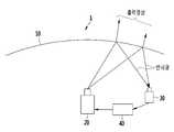
본 발명의 실시 예에 따른 표시장치(1)는 스크린(10), 프로젝터(20), 수광센서(30) 및 제어부(40)를 포함한다.A
스크린(10)은 프로젝터(20)에서 투사되는 영상 신호에 따른 영상이 출력된다.The
프로젝터(20)는 제어부(40)의 제어에 따라 스크린(10)에 프레임 단위로 영상 신호에 따른 광을 투사한다. 프로젝터(20)는 RGB 레이저 광원을 포함하고, 도트 형태로 상기 영상 신호에 따른 광을 투사하는 래스터 주사 방식의 레이저 스캐닝 프로젝터 일 수 있다. 프로젝터(20)의 RGB 레이저 광원은 내장MEMS 미러를 포함하고, 래스터 스캐닝(raster scanning)방식으로 스크린(10)에 영상 신호에 따른 광을 투사 할 수 있다. 래스터 스캐닝 방식으로 투사하므로 각 점을 뿌리는 시점의 시간과 위치가 계산될 수 있다.The
프로젝터(20)에서 투사한 광의 일부 빛은 스크린을 투과하여 출력 영상을 생성하여 출력사용자의 눈에 도달하고, 반대로 스크린을 투과되지 못한 빛은 스크린(10) 내부로 반사되어 반사광을 형성한다.Part of the light projected from the
레이저 광원에서 스크린(10)의 각 영역(점)까지 도달하는 거리 및 투사되는 광의 입사각에 따라 스크린(10)의 각 영역(점)에서 투과 및 반사되는 빛의 비율은 다르다. 특히 근거리에서의 레이저 빛은 거리에 따른 에너지가 감소하는 비율이 적으므로, 실제적으로 스크린과 레이저 빛의 입사각이 매우 중요한 요소이다. 투사광의 입사각은 레이저 광원을 기준 대비 스크린 각 영역(점)의 위치 및 스크린의 디자인(곡률)로 결정된다. 즉, 스크린(10)의 중심에서 멀어지고 스크린(10)의 곡률이 클 수록(휘어짐이 심할 수록), 스크린(10)에 투사광의 입사각은 커지게 된다. 그러므로 스크린(10)의 중심에서 멀어지고 곡률이 많이 생기는 영역일수록, 입사각이 커지게 되므로 스크린(10)의 각 영역에서 내부로 반사되는 레이저 반사광 양은 많이 지게 된다. 반사광이 많아진다는 얘기는 스크린에서 사람의 눈으로 가는 출력 영상의 빛 세기는 줄어지게 됨을 의미한다.The ratio of light transmitted and reflected at each region (point) of the
제어부(40)는 수광센서의 출력 전압을 이용하여 현재 프레임의 스크린 위치를 실시간으로 검출하고 다음 프레임의 상기 영상 신호를 제어한다.The
도 2를 참조하면, 제어부(40)는 래스터 주사 방식을 이용하여 도트 형태로 투사되는 광이 스크린(10)에 투사되는 위치를 시간 영역에서 측정할 수 있다. 제어부(40)는 현재 프레임에서 도트 형태의 광이 스크린(10)에 투사되는 위치를 측정하고, 기 설정된 현재 프레임에서의 기준 전압과 출력 전압을 비교하여 현재 프레임에서 측정된 수광센서(30)의 출력 전압이 기준을 벗어나는 비정상 위치(예를 들어, 기준을 초과하는 비정상 위치)를 시간영역에서 실시간으로 검출한다.Referring to FIG. 2, the
제어부(40)는 현재 프레임에서의 측정된 출력 전압이 기준 전압 미만이면 다음 프레임에서 비정상 위치에 투사되는 광의 출력을 높일 수 있다. 반대로, 제어부(40)는 현재 프레임에서의 측정된 출력 전압이 기준 전압을 초과하면 다음 프레임에서 비정상 위치에 투사되는 상기 광의 출력을 낮출 수 있다. 그러므로 제어부(40)는 스크린에 표시되는 영상이 스크린 전체에 균일하도록 제어 할 수 있다.The
수광센서(30)는 프로젝터(20)의 영상신호에 따른 광의 반사광 중 스크린(10) 내부로 반사되는 반사광을 측정하고 측정된 반사광에 비례하여 출력 전압을 생성한다. 예를 들어, 수광센서(30)는 반사광의 세기가 크면 높은 전압 (약 3~5V), 반사광이 크기가 적으면 로우 전압(약 0~2V)을 출력 전압을 생성 할 수 있다.The
수광센서(30)는 프로젝터(20)의 타이밍과 동기화 되어 반사광을 측정한다.The
도 3은 본 발명의 실시 예에 따른 디스플레이 장치의 구동 방법을 나타낸 흐름도이다.3 is a flowchart illustrating a method of driving a display device according to an embodiment of the present invention.
이하, 도 3을 이용하여 본 발명의 실시 예에 따른 디스플레이 방법을 설명한다.Hereinafter, a display method according to an embodiment of the present invention will be described with reference to FIG.
투사 단계(S10)에서, 프레임 단위로 영상 신호에 따른 광을 스크린에 투사한다.In the projecting step S10, light corresponding to the video signal is projected onto the screen in frame units.
반사광 측정 단계(S20)에서, 스크린 내부로 반사되는 반사광의 양에 비례한 출력 전압을 이용하여 상기 반사광의 양을 측정한다. In the reflected light measuring step (S20), the amount of the reflected light is measured using an output voltage proportional to the amount of the reflected light reflected inside the screen.
검출 단계(S30)에서, 현재 프레임에서 측정된 상기 반사광 량이 기준 이상인 비정상 위치를 검출한다.In the detecting step S30, an abnormal position in which the amount of reflected light measured in the current frame is equal to or greater than a reference value is detected.
영상 신호 제어 단계(S40)에서, 다음 프레임에서 상기 비정상 위치의 상기 영상 신호를 제어한다.In the video signal control step S40, the video signal of the abnormal position is controlled in the next frame.
이상에서 본 발명의 일 실시예에 대하여 설명하였으나, 본 발명의 사상은 본 명세서에 제시되는 실시 예에 제한되지 아니하며, 본 발명의 사상을 이해하는 당업자는 동일한 사상의 범위 내에서, 구성요소의 부가, 변경, 삭제, 추가 등에 의해서 다른 실시 예를 용이하게 제안할 수 있을 것이나, 이 또한 본 발명의 권리범위 내에 든다고 할 것이다.While the present invention has been particularly shown and described with reference to exemplary embodiments thereof, it is to be understood that the invention is not limited to the disclosed exemplary embodiments, , Changes, deletions, additions, and so forth, other embodiments may be easily suggested, but these are also within the scope of the present invention.
10: 스크린
20: 프로젝터
30: 수광센서
40: 제어부10: Screen
20: Projector
30: Light receiving sensor
40:
Claims (15)
Translated fromKorean상기 영상 신호에 따른 광 중 상기 스크린 내부로 반사되는 반사광의 양에 비례하여 출력 전압을 생성하는 수광 센서; 및
상기 수광 센서의 출력 전압을 이용하여 상기 반사광의 양을 측정하고, 현재 프레임에서 측정된 상기 출력 전압이 기 설정된 기준을 벗어나는 비정상 위치를 검출하고, 다음 프레임에서 상기 비정상 위치의 상기 영상 신호를 제어하는 제어부를 포함하고,
상기 프로젝터는 도트 형태로 상기 광을 투사하는 래스터 주사 방식의 레이저 스캐닝 프로젝터이고,
상기 수광 센서는 상기 프로젝터와 동기화 되어 상기 도트가 투사되는 시점의 시간과 위치를 계산하고,
상기 제어부는 상기 도트가 투사되는 시점의 위치에 대응하는 상기 출력 전압을 이용하여 상기 영상 신호를 제어하는 디스플레이 장치.A projector for projecting light according to a video signal on a frame-by-frame basis;
A light receiving sensor for generating an output voltage proportional to an amount of reflected light reflected in the screen of light according to the video signal; And
And detecting an abnormal position in which the output voltage measured in the current frame is out of a preset reference, and controlling the image signal in the abnormal position in a next frame And a control unit,
The projector is a laser scanning projector of a raster scan type that projects the light in a dot form,
Wherein the light receiving sensor is synchronized with the projector to calculate a time and a position at which the dot is projected,
Wherein the control unit controls the video signal using the output voltage corresponding to a position of a dot at which the dot is projected.
상기 제어부는 상기 도트 형태의 광이 상기 스크린에 투사되는 위치를 시간영역에서 검출하고, 상기 현재 프레임에서 상기 비정상 위치를 상기 시간 영역에서 검출하는 디스플레이 장치.The method according to claim 1,
Wherein the controller detects a position where the dot-shaped light is projected on the screen in a time domain, and detects the abnormal position in the time domain in the current frame.
상기 제어부는 상기 현재 프레임에서의 기준 전압과 상기 측정된 출력 전압을 비교하여 상기 비정상 위치를 검출하는 디스플레이 장치.The method of claim 3,
Wherein the controller detects the abnormal position by comparing the reference voltage in the current frame with the measured output voltage.
상기 제어부는 상기 현재 프레임에서의 상기 측정된 출력 전압이 상기 기준 전압 미만이면 다음 프레임에서 상기 비정상 위치에 투사되는 상기 광의 출력을 높이는 디스플레이 장치.5. The method of claim 4,
Wherein the controller increases the output of the light projected to the abnormal position in the next frame when the measured output voltage in the current frame is less than the reference voltage.
상기 제어부는 상기 현재 프레임에서의 상기 측정된 출력 전압이 상기 기준 전압을 초과하면 다음 프레임에서 상기 비정상 위치에 투사되는 상기 광의 출력을 낮추는 디스플레이 장치.6. The method of claim 5,
Wherein the control unit lowers the output of the light projected to the abnormal position in the next frame when the measured output voltage in the current frame exceeds the reference voltage.
상기 영상 신호에 따른 광 중 상기 스크린 내부로 반사되는 반사광의 양에 비례한 출력 전압을 이용하여 상기 반사광의 양을 측정하는 반사광 측정 단계;
현재 프레임에서 측정된 상기 반사광 량이 기준을 초과하는 비정상 위치를 검출하는 검출 단계; 및
다음 프레임에서 상기 비정상 위치의 상기 영상 신호를 제어하는 영상 신호 제어 단계를 포함하고,
상기 투사 단계는 도트 형태로 상기 광을 투사하는 래스터 주사 방식의 레이저 스캐닝 프린터를 이용하고,
상기 검출 단계는, 상기 레이저 스캐닝 프린터와 동기화된 수광 센서를 이용하여 상기 도트가 투사되는 시점의 시간과 위치를 계산하는 단계를 포함하고,
상기 신호 제어 단계는, 상기 도트가 투사되는 시점의 위치에 대응하는 상기 출력 전압을 이용하여 상기 영상 신호를 제어하는 디스플레이 방법.A projection step of projecting light according to an image signal on a frame-by-frame basis;
A reflected light measuring step of measuring an amount of the reflected light by using an output voltage proportional to the amount of reflected light reflected in the screen among the light according to the video signal;
A detecting step of detecting an abnormal position in which the amount of reflected light measured in the current frame exceeds a reference; And
And controlling the video signal of the abnormal position in a next frame,
Wherein the projecting step uses a laser scanning printer of a raster scan type for projecting the light in a dot shape,
Wherein the detecting step includes calculating a time and a position of the dot when the dot is projected using a light receiving sensor synchronized with the laser scanning printer,
Wherein the signal control step controls the video signal by using the output voltage corresponding to a position of a point at which the dot is projected.
상기 검출 단계는 상기 래스터 주사 방식을 이용하여 상기 도트 형태의 광이 상기 스크린에 투사되는 위치를 시간영역에서 검출하고, 상기 현재 프레임에서 상기 비정상 위치를 상기 시간 영역에서 검출하는 디스플레이 방법.9. The method of claim 8,
Wherein the detecting step detects the position where the dot-shaped light is projected on the screen in the time domain using the raster scanning method, and detects the abnormal position in the time domain in the current frame.
상기 검출 단계는 상기 현재 프레임에서의 기준 전압과 상기 출력 전압을 비교하여 상기 비정상 위치를 검출하는 디스플레이 방법.12. The method of claim 11,
Wherein the detecting step detects the abnormal position by comparing the reference voltage and the output voltage in the current frame.
신호 제어 단계는 상기 현재 프레임에서의 상기 출력 전압이 상기 기준 전압을 초과하면 다음 프레임에서 상기 비정상 위치에 투사되는 상기 광의 출력을 낮추는 단계를 포함한 디스플레이 방법.13. The method of claim 12,
And the signal control step includes lowering the output of the light projected to the abnormal position in the next frame when the output voltage in the current frame exceeds the reference voltage.
신호 제어 단계는 상기 현재 프레임에서의 상기 출력 전압이 상기 기준 전압 미만이면 다음 프레임에서 상기 비정상 위치에 투사되는 상기 광의 출력을 높이는 단계를 포함한 디스플레이 방법.
14. The method of claim 13,
Wherein the signal control step includes increasing the output of the light projected to the abnormal position in the next frame if the output voltage in the current frame is less than the reference voltage.
Priority Applications (4)
| Application Number | Priority Date | Filing Date | Title |
|---|---|---|---|
| KR1020130159595AKR101575313B1 (en) | 2013-12-19 | 2013-12-19 | Curved display device and display method using the same |
| US14/446,895US9609295B2 (en) | 2013-12-19 | 2014-07-30 | Display device and method for adjustment of an image |
| DE102014215692.0ADE102014215692B4 (en) | 2013-12-19 | 2014-08-07 | Display device and method |
| CN201410426280.2ACN104735429B (en) | 2013-12-19 | 2014-08-26 | Display device and display methods |
Applications Claiming Priority (1)
| Application Number | Priority Date | Filing Date | Title |
|---|---|---|---|
| KR1020130159595AKR101575313B1 (en) | 2013-12-19 | 2013-12-19 | Curved display device and display method using the same |
Publications (2)
| Publication Number | Publication Date |
|---|---|
| KR20150072528A KR20150072528A (en) | 2015-06-30 |
| KR101575313B1true KR101575313B1 (en) | 2015-12-08 |
Family
ID=53275575
Family Applications (1)
| Application Number | Title | Priority Date | Filing Date |
|---|---|---|---|
| KR1020130159595AActiveKR101575313B1 (en) | 2013-12-19 | 2013-12-19 | Curved display device and display method using the same |
Country Status (4)
| Country | Link |
|---|---|
| US (1) | US9609295B2 (en) |
| KR (1) | KR101575313B1 (en) |
| CN (1) | CN104735429B (en) |
| DE (1) | DE102014215692B4 (en) |
Families Citing this family (3)
| Publication number | Priority date | Publication date | Assignee | Title |
|---|---|---|---|---|
| US11308601B2 (en)* | 2015-04-29 | 2022-04-19 | Emhart Glass S.A. | Container inspection system with individual light control |
| CN106060615B (en)* | 2016-05-23 | 2020-05-22 | Tcl海外电子(惠州)有限公司 | Judgment method and device for realizing screen parameter automatic matching by using optical sensor |
| CN111031638A (en)* | 2019-12-26 | 2020-04-17 | 深圳市洲明科技股份有限公司 | Abnormal voltage detection method and device based on LED lamp beads |
Citations (3)
| Publication number | Priority date | Publication date | Assignee | Title |
|---|---|---|---|---|
| JP2005101825A (en) | 2003-09-24 | 2005-04-14 | Nec Viewtechnology Ltd | Projector with mechanism for measuring intensity of reflected light |
| JP2010507128A (en) | 2006-10-19 | 2010-03-04 | ポリマー、ビジョン、リミテッド | Front lighting of rollable or wrappable display devices |
| JP2011530209A (en) | 2008-07-30 | 2011-12-15 | マイクロビジョン,インク. | Overlaid projection of scanned rays |
Family Cites Families (9)
| Publication number | Priority date | Publication date | Assignee | Title |
|---|---|---|---|---|
| US4701020A (en) | 1986-09-18 | 1987-10-20 | North American Philips Consumer Electronics Corp. | Rear projection screen with improved luminance uniformity |
| GB9008031D0 (en) | 1990-04-09 | 1990-06-06 | Rank Brimar Ltd | Projection systems |
| CN1281054C (en)* | 2002-04-02 | 2006-10-18 | 晶荧光学科技有限公司 | Calibration method for improving evenness of digital projection display system |
| JP2004184852A (en)* | 2002-12-05 | 2004-07-02 | Olympus Corp | Display device, light source device, and lighting device |
| JP5326352B2 (en)* | 2008-05-13 | 2013-10-30 | 船井電機株式会社 | Image display device |
| TWI427616B (en)* | 2009-10-01 | 2014-02-21 | Genesys Logic Inc | Light compensation scheme, optical machine device, display system and method for light compensation |
| US8585206B2 (en) | 2010-06-29 | 2013-11-19 | Corning Incorporated | Methods for operating scanning laser projectors to reduce speckle and image flicker |
| KR101717527B1 (en) | 2010-11-17 | 2017-03-27 | 엘지전자 주식회사 | laser projector and method for compensating brightness of the same |
| KR20120099845A (en) | 2011-03-02 | 2012-09-12 | 엘지전자 주식회사 | A laser projector and a method of processing a signal thereof |
- 2013
- 2013-12-19KRKR1020130159595Apatent/KR101575313B1/enactiveActive
- 2014
- 2014-07-30USUS14/446,895patent/US9609295B2/enactiveActive
- 2014-08-07DEDE102014215692.0Apatent/DE102014215692B4/enactiveActive
- 2014-08-26CNCN201410426280.2Apatent/CN104735429B/enactiveActive
Patent Citations (3)
| Publication number | Priority date | Publication date | Assignee | Title |
|---|---|---|---|---|
| JP2005101825A (en) | 2003-09-24 | 2005-04-14 | Nec Viewtechnology Ltd | Projector with mechanism for measuring intensity of reflected light |
| JP2010507128A (en) | 2006-10-19 | 2010-03-04 | ポリマー、ビジョン、リミテッド | Front lighting of rollable or wrappable display devices |
| JP2011530209A (en) | 2008-07-30 | 2011-12-15 | マイクロビジョン,インク. | Overlaid projection of scanned rays |
Also Published As
| Publication number | Publication date |
|---|---|
| CN104735429B (en) | 2018-02-06 |
| CN104735429A (en) | 2015-06-24 |
| US9609295B2 (en) | 2017-03-28 |
| KR20150072528A (en) | 2015-06-30 |
| US20150181184A1 (en) | 2015-06-25 |
| DE102014215692A1 (en) | 2015-06-25 |
| DE102014215692B4 (en) | 2023-10-05 |
Similar Documents
| Publication | Publication Date | Title |
|---|---|---|
| US7631974B2 (en) | Image display method and image display device | |
| US9723281B2 (en) | Projection apparatus for increasing pixel usage of an adjusted projection area, and projection method and program medium for the same | |
| JP6135389B2 (en) | Image display device and optical component | |
| US10672349B2 (en) | Device for project an image | |
| US20180013995A1 (en) | Projection system and method for adjusting projection system | |
| US10088742B2 (en) | Laser projection display system configured to execute scanning with laser light in accordance with image signals | |
| KR20120026109A (en) | Projection-type display and control thereof | |
| JP2006319950A (en) | Video display device | |
| US7484854B2 (en) | Projector and pattern image display method | |
| US10078258B2 (en) | Projection device, projection device control method, projection device control apparatus, and computer program thereof | |
| KR20070076338A (en) | Video playback device and control method | |
| US10674122B2 (en) | Light source unit and projection-type display | |
| JP2014130256A (en) | Image display device, image display method, and program | |
| KR101575313B1 (en) | Curved display device and display method using the same | |
| JP2009222973A (en) | Image projection device | |
| JP2014186068A (en) | Image display device | |
| JP6836176B2 (en) | Display device and control method of display device | |
| JP6106565B2 (en) | Video projection device | |
| JP6191019B2 (en) | Projection apparatus and projection method | |
| US10419729B2 (en) | Adjustment image generating device, adjustment image generating method, and storage medium having program stored therein | |
| US10473918B2 (en) | Image drawing device and image drawing method that detects and controls laser light | |
| US11146766B2 (en) | Projection-type video display device | |
| JP6182739B2 (en) | Projection apparatus and projection method | |
| JP6439254B2 (en) | Image projection apparatus, control method for image projection apparatus, and control program for image projection apparatus | |
| JP2010211149A (en) | Image display |
Legal Events
| Date | Code | Title | Description |
|---|---|---|---|
| A201 | Request for examination | ||
| PA0109 | Patent application | Patent event code:PA01091R01D Comment text:Patent Application Patent event date:20131219 | |
| PA0201 | Request for examination | ||
| E902 | Notification of reason for refusal | ||
| PE0902 | Notice of grounds for rejection | Comment text:Notification of reason for refusal Patent event date:20150225 Patent event code:PE09021S01D | |
| PG1501 | Laying open of application | ||
| E701 | Decision to grant or registration of patent right | ||
| PE0701 | Decision of registration | Patent event code:PE07011S01D Comment text:Decision to Grant Registration Patent event date:20151022 | |
| GRNT | Written decision to grant | ||
| PR0701 | Registration of establishment | Comment text:Registration of Establishment Patent event date:20151201 Patent event code:PR07011E01D | |
| PR1002 | Payment of registration fee | Payment date:20151201 End annual number:3 Start annual number:1 | |
| PG1601 | Publication of registration | ||
| FPAY | Annual fee payment | Payment date:20191127 Year of fee payment:5 | |
| PR1001 | Payment of annual fee | Payment date:20191127 Start annual number:5 End annual number:5 | |
| PR1001 | Payment of annual fee | Payment date:20201126 Start annual number:6 End annual number:6 | |
| PR1001 | Payment of annual fee | Payment date:20231120 Start annual number:9 End annual number:9 | |
| PR1001 | Payment of annual fee | Payment date:20241125 Start annual number:10 End annual number:10 |