KR101573304B1 - Mounting clip - Google Patents
Mounting clipDownload PDFInfo
- Publication number
- KR101573304B1 KR101573304B1KR1020117020504AKR20117020504AKR101573304B1KR 101573304 B1KR101573304 B1KR 101573304B1KR 1020117020504 AKR1020117020504 AKR 1020117020504AKR 20117020504 AKR20117020504 AKR 20117020504AKR 101573304 B1KR101573304 B1KR 101573304B1
- Authority
- KR
- South Korea
- Prior art keywords
- clip
- tee
- lattice
- delete delete
- offset
- Prior art date
- Legal status (The legal status is an assumption and is not a legal conclusion. Google has not performed a legal analysis and makes no representation as to the accuracy of the status listed.)
- Expired - Fee Related
Links
Images


Classifications
- E—FIXED CONSTRUCTIONS
- E04—BUILDING
- E04B—GENERAL BUILDING CONSTRUCTIONS; WALLS, e.g. PARTITIONS; ROOFS; FLOORS; CEILINGS; INSULATION OR OTHER PROTECTION OF BUILDINGS
- E04B9/00—Ceilings; Construction of ceilings, e.g. false ceilings; Ceiling construction with regard to insulation
- E04B9/30—Ceilings; Construction of ceilings, e.g. false ceilings; Ceiling construction with regard to insulation characterised by edge details of the ceiling; e.g. securing to an adjacent wall
- E—FIXED CONSTRUCTIONS
- E04—BUILDING
- E04B—GENERAL BUILDING CONSTRUCTIONS; WALLS, e.g. PARTITIONS; ROOFS; FLOORS; CEILINGS; INSULATION OR OTHER PROTECTION OF BUILDINGS
- E04B9/00—Ceilings; Construction of ceilings, e.g. false ceilings; Ceiling construction with regard to insulation
- E—FIXED CONSTRUCTIONS
- E04—BUILDING
- E04B—GENERAL BUILDING CONSTRUCTIONS; WALLS, e.g. PARTITIONS; ROOFS; FLOORS; CEILINGS; INSULATION OR OTHER PROTECTION OF BUILDINGS
- E04B9/00—Ceilings; Construction of ceilings, e.g. false ceilings; Ceiling construction with regard to insulation
- E04B9/006—Ceilings; Construction of ceilings, e.g. false ceilings; Ceiling construction with regard to insulation with means for hanging lighting fixtures or other appliances to the framework of the ceiling
- E—FIXED CONSTRUCTIONS
- E04—BUILDING
- E04B—GENERAL BUILDING CONSTRUCTIONS; WALLS, e.g. PARTITIONS; ROOFS; FLOORS; CEILINGS; INSULATION OR OTHER PROTECTION OF BUILDINGS
- E04B9/00—Ceilings; Construction of ceilings, e.g. false ceilings; Ceiling construction with regard to insulation
- E04B9/06—Ceilings; Construction of ceilings, e.g. false ceilings; Ceiling construction with regard to insulation characterised by constructional features of the supporting construction, e.g. cross section or material of framework members
- E04B9/10—Connections between parallel members of the supporting construction
- F—MECHANICAL ENGINEERING; LIGHTING; HEATING; WEAPONS; BLASTING
- F16—ENGINEERING ELEMENTS AND UNITS; GENERAL MEASURES FOR PRODUCING AND MAINTAINING EFFECTIVE FUNCTIONING OF MACHINES OR INSTALLATIONS; THERMAL INSULATION IN GENERAL
- F16B—DEVICES FOR FASTENING OR SECURING CONSTRUCTIONAL ELEMENTS OR MACHINE PARTS TOGETHER, e.g. NAILS, BOLTS, CIRCLIPS, CLAMPS, CLIPS OR WEDGES; JOINTS OR JOINTING
- F16B7/00—Connections of rods or tubes, e.g. of non-circular section, mutually, including resilient connections
- F16B7/18—Connections of rods or tubes, e.g. of non-circular section, mutually, including resilient connections using screw-thread elements
Landscapes
- Engineering & Computer Science (AREA)
- Architecture (AREA)
- Physics & Mathematics (AREA)
- Electromagnetism (AREA)
- Civil Engineering (AREA)
- Structural Engineering (AREA)
- General Engineering & Computer Science (AREA)
- Mechanical Engineering (AREA)
- Connection Of Plates (AREA)
- Vehicle Interior And Exterior Ornaments, Soundproofing, And Insulation (AREA)
- Finishing Walls (AREA)
- Clamps And Clips (AREA)
- Residential Or Office Buildings (AREA)
- Installation Of Indoor Wiring (AREA)
- Grates (AREA)
Abstract
Translated fromKoreanDescription
Translated fromKorean본 발명은 전반적으로 현수 천장에 관한 것으로, 특히 이러한 현수 천장의 노출된 에지를 따라 트림을 제공하기 위한 신규의 개선된 장착 클립 또는 브래킷에 관한 것이다.The present invention relates generally to a suspended ceiling, and more particularly to a novel improved mounting clip or bracket for providing a trim along the exposed edges of such suspended ceilings.
소정의 응용 또는 설치에서, 현수 천장은 깔끔한 마감된 외관을 위해 트림을 필요로 하는 노출된 에지를 가진다. 예를 들어, 일부 현수 천장은 인접한 천장면보다 통상 아래에서 다양한 레벨에 현수되는 아일랜드를 구비한다. 이러한 아일랜드는 천장의 다른 부분 및 벽으로부터 이격된 노출된 에지를 가진다. 이러한 노출된 에지가 소정의 방식으로 트리밍되지 않는다면, 마감되지 않은 외관을 가지게 된다.In certain applications or installations, the suspended ceiling has exposed edges that require a trim for a clean, finished appearance. For example, some hanging ceilings have an island that is suspended at various levels below the adjacent ceiling surface. These islands have exposed edges spaced apart from other parts of the ceiling and walls. If such exposed edges are not trimmed in any way, they will have an unfinished appearance.
일부 응용에서, 천장은 벽으로부터 이격된 위치 또는 인접 벽이 존재하지 않는 위치에서 종결될 수 있다. 여기서 다시, 마감용 트림이 제공되지 않으면, 마감되지 않은 에지가 보일 수 있다.In some applications, the ceiling may terminate at a location spaced from the wall or at a location where there is no adjacent wall. Here again, if a trim trim is not provided, an unfinished edge may be visible.
현수 천장의 노출된 에지는 다양한 방식으로 트리밍되었다. 예를 들어, 쇼핏 타입 스터브 벽이 대략 현수 천장의 레벨까지 아래로 연장되어 구성될 수 있다. 다음으로, 현수 천장은 이러한 스터브 벽으로 연장되어 통상의 방식으로 설치된다. 따라서, 별개로 구성되고 건물 구조에 의해 지지되어야 하는 쇼핏 그 자체가 현수 천장의 노출된 에지에 해당하는 부분을 위해 트림을 제공한다. 다른 방법으로, 예를 들어 채널형 또는 L자형 부재일 수 있는 트림 부재가 리벳 또는 나사에 의해 격자의 하면에 고정된다. 이러한 방법들은 모두 노동 집약적이고 고비용이다. 아울러, 후자의 방법에서, 리벳 또는 나사가 노출되어 보이고 천장의 마감된 외관을 훼손한다.The exposed edges of the suspended ceiling were trimmed in various ways. For example, the short-type stub wall may be configured to extend down to approximately the level of the suspended ceiling. Next, the suspension ceiling is installed in a conventional manner extending to such a stub wall. Thus, the showpiece itself, which is constructed separately and must be supported by the building structure, provides a trim for the portion corresponding to the exposed edges of the suspension ceiling. Alternatively, a trim member, for example a channel or L-shaped member, is fixed to the lower surface of the grating by a rivet or a screw. All of these methods are labor intensive and costly. In addition, in the latter method, rivets or screws are exposed and undermine the finished appearance of the ceiling.
본 발명의 양수인에게 양도된 미국 특허 제4,744,188호에 개시된 바와 같은 직접 장착된 트림 부재는 대략 채널 형상으로 이루어지고 하부 레그를 제공하며, 상기 하부 레그가 격자 티의 플랜지 아래에 끼워맞춤된다. 채널의 상부 레그는 격자 티의 벌브에 고정된다. 이러한 트림 부재는 오직 천장의 노출된 에지를 따라 설치될 수 있고, 여기서 격자 티 부재는 에지와 평행하게 연장되며, 트림 부재는 피복될 노출된 에지 및 격자의 높이에 따라 크기가 결정된다. 이 특허의 개시내용은 이에 참조로서 포함된다.A directly mounted trim member, such as that disclosed in U.S. Patent No. 4,744,188, assigned to the assignee of the present invention, is generally channel shaped and provides a lower leg which is fitted under the flange of the lattice tee. The upper leg of the channel is fixed to the bulb of the grating tee. These trim members can be installed along only the exposed edges of the ceiling where the lattice members extend parallel to the edges and the trim members are sized according to the height of the exposed edges and lattice to be covered. The disclosure of which is incorporated herein by reference.
본 발명의 양수인에게 양도된 관련 미국 특허 제5,195,289호 및 제5,201,787호는 수 개의 트림 부재 장착용 클립 시스템들을 제공하며, 이는 메인 및 크로스 격자 티 방향에 대해 트림 부재의 각진 장착을 가능하게 한다. 일 배치에서, 클립 시스템은 채널 트림 부재를 수용하기 위해 수직으로 배치된 지지면을 가진 격자 티 벌브의 상부에 스냅핑되는 U자형 지지부를 포함한다. 다른 클립은 트림 부재에 연결가능한 수직의 지지면의 선회 이동을 위해 격자 티의 상면에 리벳팅되는 지지부를 포함한다. 종종 은촉이음된 패널과 함께 사용되는 개방 채널 박스형 지지부 및 T자형 격자 티 패널과 같이, 다양한 높이와 구성을 가진 티 격자와 함께 사용되기 위해 다양한 클립들의 크기가 결정된다. 각각의 클립은 고정된 상대 높이에서 해당 격자 티에 장착되도록 구성되고, 트림 부재는 격자 티 높이를 넘어 연장되는 가시적 마감면을 구비한다. 이러한 특허들의 개시내용은 이에 참조로서 포함된다.U.S. Pat. Nos. 5,195,289 and 5,201,787, assigned to the assignee of the present invention, provide several clip member mounting clip systems that enable angled mounting of the trim member with respect to the main and cross lattice Ti directions. In one arrangement, the clip system includes a U-shaped support that is snapped to the top of the lattice bulb having a support surface disposed vertically to receive the channel trim member. The other clip includes a support which is riveted to the upper surface of the lattice frame for pivotal movement of the vertical support surface connectable to the trim member. The size of the various clips is often determined for use with a tee grating having various heights and configurations, such as an open channel boxed support and T-shaped lattice TEE panels, which are often used with a clam shell panel. Each clip is configured to be mounted to a respective lattice tee at a fixed relative height, and the trim member has a visible finish surface extending beyond the lattice tee height. The disclosures of these patents are incorporated herein by reference.
격자 티 중앙 웨브 또는 벌브에 고정되는 평탄한 장착 레그를 가진 L자형 클립을 사용하는 것이 또한 공지되어 있다. 장착 레그는 트림 부재에 부착가능한 직각면부로 연장된다. 시각적 정렬 판단에 따라, 설치자는 원하는 위치에서 장착 레그를 통한 나사 또는 리벳 체결에 의해 클립을 격자에 고정하여, 격자 및 하부 천장면에 대해 트림 높이를 고정하는 한편, 천장의 노출된 에지의 피복을 유지한다. 시각적 정렬의 정확도 상의 모든 오차는 트림 부재의 길이로 인해 시각적으로 알아채기 쉽다. 또한, 편평한 장착 레그는 측방향으로 연장된 트림 부재에서 기인한 격자 티의 종축을 중심으로 하는 비틀림 하중에 잘 저항하는 것으로 밝혀지지 않았다.It is also known to use an L-shaped clip with a flat mounting leg that is secured to the lattice center web or bulb. The mounting leg extends to a right-angled surface portion that is attachable to the trim member. According to the visual alignment determination, the installer fixes the clip to the grid by screwing or riveting through the mounting leg at the desired location to fix the trim height to the grid and underlying ceiling scene, . All errors in the accuracy of visual alignment are visually noticeable due to the length of the trim member. It has also not been found that the flat mounting legs resist well the torsional load centered on the longitudinal axis of the lattice frame resulting from the laterally extending trim member.
후자의 클립의 변형예는, 면부에 조정가능하게 위치되어 트림 부재 부착 위치 및 트림 부재와 티 격자의 상대 높이를 변화시킬 수 있는 수직 슬라이드를 포함한다. 그 결과로, 고비용의 다부품 클립 조립체가 형성되고, 이는 설치자의 시각적 정렬에 여전히 의존한다.
A modification of the latter clip includes a vertical slide which is adjustably positioned on the surface and which can change the position of the trim member attachment and the relative height of the trim member and the T-grid. As a result, a costly multi-part clip assembly is formed, which still depends on the visual alignment of the installer.
본 발명은 현수 천장의 노출된 에지를 따라 트림 부재 또는 스트립을 장착하기 위한 신규의 개선된 클립 또는 브래킷 구성을 제공한다.The present invention provides a novel improved clip or bracket arrangement for mounting trim members or strips along exposed edges of a suspension ceiling.
클립은 격자 티에 연결되는 지지부, 및 트림 부재를 지지하는 면부를 포함한다.The clip includes a supporting portion connected to the lattice tee, and a surface portion supporting the trim member.
클립의 지지부는 오프셋 클립 벽들 및 접촉면들을 포함한다. 오프셋 클립 벽들은 티 격자의 일 측으로부터 오프셋 격자 티 벽들과 맞물리도록 배치된다. 클립이 격자에 장착됨에 따라, 오프셋 클립 벽들은 오프셋 티 벽들과 슬라이딩 방식으로 맞물리고 이들을 따라 원하는 상부 또는 하부 상대 높이 위치로 이동된다. 클립 접촉면들은 상부 또는 하부 상대 높이 위치에서 수직 슬라이딩 이동을 제한하는 티 접촉면들과 맞물린다.The support of the clip includes offset clip walls and contact surfaces. The offset clip walls are arranged to engage the offset grid tee walls from one side of the tee grille. As the clip is mounted to the grid, the offset clip walls slide in sliding contact with the offset tee walls and are moved along these to the desired upper or lower relative height position. The clip contact surfaces engage the tee contact surfaces that limit vertical sliding movement at the upper or lower relative height position.
협력하는 오프셋 클립 벽들과 오프셋 티 벽들 및 접촉면들은 티 격자 및 결합 천장 타일에 대해 클립의 높이 위치를 인덱싱하는 역할을 한다. 그러므로, 설치자는 시각적 정렬에만 의지하는 것이 아니라, 클립 벽들과 티 벽들 및 접촉면들의 맞물림의 도움을 받아 부재들을 올바로 정렬시키고 클립을 선택된 상대 높이에 위치시킨다.The cooperating offset clip walls and offset tee walls and contact surfaces serve to index the height position of the clip relative to the tee grille and the joining ceiling tile. Therefore, the installer relies not only on visual alignment, but also with the help of the engagement of the clip walls and the tee walls and contact surfaces to properly align the members and position the clip at the selected relative height.
오프셋 클립 벽들은 이격된 격자 티 벽들과 다양한 위치 쌍에서 맞물리고, 그로 인해 측방향으로 연장된 트림 부재에 의해 격자 티의 길이 주위에 부과되는 비틀림 하중에 대한 연결 또는 장착 안정성을 또한 강화한다. 이런 방식으로, 오프셋 클립 벽들과 오프셋 티 벽들은 벽 결합 쌍들을 제공하고, 이들은 협력하여 격자 티의 왜곡과 비틀림 하중에 대한 저항력을 증가시킨다.The offset clip walls also engage in spaced pairs of spaced lattice bridges thereby enhancing the connection or mounting stability to torsional loads imposed by the laterally extending trim member about the length of the lattice frame. In this way, the offset clip walls and offset tee walls provide wall coupling pairs, which in combination increase the distortion and torsional load resistance of the lattice tee.
클립은 대략 L자 형상으로 이루어지되, 지지부가 L자 형상의 일 레그를 따라 구비되고, 면부가 L자 형상의 타 레그를 따라 구비된다. 단일 클립은 편평한 패널을 지지하는 편평한 대향 플랜지들을 가진 통상의 T자형 격자 티, 또는 하부 천장 패널의 장착 클립을 수용하는 하향 개방 채널을 가진 개방 채널 격자티와 사용될 수 있다. 다양한 격자 티 스타일들 각각은 고정된 수직 및 수평 치수로 상업적으로 이용가능하다. 예를 들어, USG 코퍼레이션의 DXT T자형 격자 티는 CENTRICITEE®상표로 판매되고, DXT 개방 채널 격자는 FINELINE®상표로 판매되며, CELEBRATION®브랜드의 하부 현수 금속 천장 패널 및 은촉이음된 에지를 가진 음향 패널과 사용되기 위한 것이다.The clip is formed in a substantially L-shape, and the support portion is provided along one L-shaped leg, and the face portion is provided along the L-shaped other leg. The single clip may be used with a conventional T-shaped lattice tee with flat opposing flanges supporting a flat panel, or with an open channel lattice tee having a downwardly open channel to receive the mounting clip of the lower ceiling panel. Each of the various lattice Ti styles is commercially available with fixed vertical and horizontal dimensions. For example, USG Corporation's DXT T-shaped lattice tees are sold under the CENTRICITEE® trademark, DXT open channel gratings are sold under the FINELINE® trademark, and the CELEBRATION® brand bottom suspension metal ceiling panels and acoustic panels with clipped edges And to be used with.
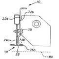
도 1은 본 발명에 따른 지지부와 면부를 가진 장착 클립의 사시도이다.
도 2는 특히 지지부의 평면도와 면부의 측면도를 보여주는 클립의 입측면도이다.
도 3은 특히 면부의 평면도와 지지부의 측면도를 보여주는 클립의 입단부도이다.
도 4는 T자형 격자 티에 장착된 클립을 구비한 현수 천장 아일랜드를 보여주는 부분 단면 입측면도로, 클립 면부가 트림 부재에 연결되어 있다.
도 5는 도 4의 T자형 격자 티에 고정될 준비가 되어있는, 상부 위치의 장착 클립을 보여주는 개략적인 부분 단면도이다.
도 6은 T자형 격자 티에 고정될 준비가 되어있는, 하부 위치의 장착 클립을 보여주는 도 5와 유사한 개략도이다.
도 7은 개방 채널 격자의 박스부에 안착되고 이에 고정될 준비가 되어있는, 상부 위치의 장착 클립을 보여주는 개략적인 부분 단면도이다.
도 8은 개방 채널 격자의 대향 측에 고정될 준비가 되어있는, 최저 위치의 장착 클립을 보여주는 도 7과 유사한 개략도이다.1 is a perspective view of a mounting clip having a support and a face according to the present invention;
Figure 2 is a mouth side view of a clip showing a top view and a side view of the surface, in particular, of the support.
Fig. 3 is a perspective view of the clip showing in particular a plan view of the face part and a side view of the support part; Fig.
Fig. 4 is a partial cross-sectional side view of a suspended ceiling island with a clip mounted on a T-shaped lattice tee, with the clip surface portion being connected to the trim member.
Figure 5 is a schematic partial cross-sectional view showing the mounting clip in the upper position ready to be fixed to the T-shaped lattice tee of Figure 4;
Figure 6 is a schematic view similar to Figure 5 showing a mounting clip in a lower position ready to be fixed to a tee lattice tee;
7 is a schematic partial cross-sectional view showing a mounting clip in an upper position, which is seated in a box portion of an open channel grating and is ready to be fixed thereto.
Fig. 8 is a schematic view similar to Fig. 7 showing the mounting position of the lowest position, ready to be fixed on the opposite side of the open channel grille.
도 1 내지 도 4를 참조하면, 장착 클립(10)은, 대략 L자형으로 절곡되어 지지부(14) 및 수직의 면부(16)를 제공하는 금속 스트립(12)으로 형성된다. 도 4에 도시된 바와 같이, 지지부(14)는 격자 티(18)의 단부와 정렬되고 이에 고정되도록 배치되고, 면부(16)는 그로부터 연장되어 트림 부재(20)를 지지한다.Referring to Figs. 1-4, the
지지부(14)는 각진 연결벽(26)에 의해 결합되는 오프셋 벽들 또는 벽 부분들(22, 24)을 포함한다. 벽 부분들(22, 24)은 대략 평행한 평면들의 형태로 연장된다. 벽 부분들(22, 24)은 별개의 부재들로 형성될 수 있지만, 도시된 실시형태에서는 단일 금속 스트립(12)을 절곡함에 의해 이격된 벽 부분들을 형성하는 것이 편리하다.The
지지부(14)는 벽(24)의 하부 에지에 의해 형성된 제1 접촉면(28), 벽 부분(22)으로부터 절곡된 금속 탭(32)에 의해 형성된 제2 접촉면(30), 및 벽 부분(22)의 각지게 배치된 상부 에지 영역에 의해 형성된 제3 접촉면(34)을 포함한다. 접촉면들은 격자 티(18) 상에서 클립(10)의 수직 위치를 위치 결정 또는 고정한다.The
본원에서, 편의상, 도 1에 도시된 바와 같이 관찰자로부터 원거리의 클립(10) 측 또는 면을 "A"측으로 지칭하고, 클립(10)의 인접측 또는 면을 "B"측 또는 면으로 지칭한다. 유사한 방식으로, 격자 티(18)의 원거리측 또는 면이 "A"측이고, 인접측이 "B"측이다. 이하, 일 측 또는 타 측을 나타내기 위해 소문자 "a" 또는 "b"를 부분 또는 면의 도면 부호에 추가함에 의해, 클립과 격자 티의 다양한 요소들 또는 면들을 유사하게 나타낼 수 있다.Here, for convenience, the
지지부(14)는, 벽 부분(22)을 형성하는 금속 스트립(12)과 일체로 형성되고 이로부터 직각으로 견고하게 연장되는 대략 평탄한 벽(36)을 포함한다. 후술되는 바와 같이, 벽(36)은 트림 부재(20)를 고정하기 위한 나사산 고정나사 홀(38), 및 트림 부재(20)와의 연결을 용이하게 하는 경사진 코너(40)를 포함한다.The
도 4에 도시된 바와 같이, 격자 티(18)는 건물 구조(미도시) 또는 건물 구조에 고정된 주 현수 천장(44)에 고정되는 복수의 행거 와이어(42; 하나만 도시됨)에 의해 대략 수평 위치에 지지된다. 격자 티(18)는 주 천장(44) 아래에 배치된 아일랜드 현수 천장(46)을 형성하는 복수의 상호 연결된 격자 티들 중 메인 러너 또는 크로스 러너일 수 있다. 아일랜드(46)는 격자 티들에 의해 지지된 복수의 천장 패널(48; 하나만 점선으로 일부 도시됨)을 포함한다.4, the
도 4에 도시된 바와 같이, 트림 부재(20)는 천장(46)의 노출된 에지(50)를 따라 위치되도록 도면 평면 내로 연장되는 길이 및 대략 L자형 횡단면을 가진다. 특히, 트림 부재(20)는 측방향 레그(54)로부터 직각으로 연장되는 직립형 레그(52)를 포함한다. 직립형 레그(52)는 대략 격자 티(18)의 하부 말단 및 클립(10)의 상부 말단에 대응하는 노출된 에지(50)의 높이와 거의 동일한 높이를 가진다. 측방향 레그(54)는 노출된 에지(50)로부터 측방향으로 충분한 길이만큼 연장되어, 트림 코너가 교차하는 노출된 에지에 형성되게 한다.As shown in FIG. 4, the
직립형 레그(52)는 아래로부터 적어도 부분적으로 보일 수 있는 마감면(56)을 가진다. 유사하게, 측방향 레그(54)는 아래로부터 보일 수 있는 마감면(58), 및 또한 아래로부터 적어도 부분적으로 보일 수 있는 귀환면(62)을 포함하는 바브단(60; barbed end)을 가진다. 마감면들은 협력하여 노출된 에지(50)를 피복하는 마감된 에지를 아일랜드(46)에 제공한다. 트림 부재는 알루미늄 압출부로 형성되고 분말 코팅되어 장식적인 마감면을 제공할 수 있다.The
대향하는 장착 암들(64)이 레그(56)의 후방측을 따라 연장되어, 클립(10)의 면부(16)의 벽(36)을 수용하는 채널(66)을 형성한다. 클립(10)을 도 3의 도시로부터 약간 반시계방향으로 배향시키고, 벽(36)의 하부 경사진 코너(39)를 하부 암(64)의 채널(66) 내에 위치시키며, 벽의 경사진 코너(40)가 상부 장착 암(64)의 채널(66) 내에 위치하도록 클립을 시계방향으로 제한된 각도만큼 회전시킴에 의해, 클립(10)을 초기에 트림 부재(20)에 조립한다. 이러한 운동으로 인해, 잠금 톱니(68)가 하부 암(64)의 상면을 죄어 도 3의 배향의 클립(10)을 반시계방향 회전에 반해 고정하고, 그에 따라 면부(16)를 채널(66) 내에 포획한다. 다음으로, 나사산 고정나사 홀(38)에 수용된 고정나사(70)를 레그(56)의 후방측에 조임에 의해, 장착된 클립(10)을 원하는 위치에서 느슨하게 트림 부재에 고정할 수 있다. 다음으로, 조립된 클립(10)과 트림 부재(20)는 후술하는 바와 같이 격자 티(18)에 장착될 수 있다.Opposing mounting
도 5를 참조하면, 격자 티(18)에 설치된 클립(10)이 개략적으로 도시되고, 트림 부재(20)는 생략되어 있다. 도시된 바와 같이, 클립(10)의 A측이 격자 티(18)의 B측에 장착된다. 도 5에 도시된 바와 같이, 격자 티(18)는 양방향 대칭이고, 상부 벽(73)이 아래로 매달린 벌브 측벽들(72a, 72b)로 연장된 대략 장방형의 폐쇄 벌브(72)를 포함한다. 측벽들(72a, 72b)은 하부 경사진 벌브 벽들(72a', 72b')로 연장되고, 이들은 각각 중앙 벽들(74a, 74b)을 결합시켜 중앙 웨브 벽(74)을 형성한다. 중앙 벽들(74a, 74b)의 하부 에지에서, 플랜지들(76a, 76b)이 격자 티(18)의 대향 측(A, B)에 연장된다. 천장 패널들(48)은 섬유 또는 폼과 같은 압축성 재료로 형성되고, 클립(10)에 인접한 패널부들은 플랜지 상에서 패널 지지 및/또는 패널 정렬의 손실 없이 압축될 수 있다.Referring to Fig. 5, a
도 5에서, 클립(10)은 상부 위치에 장착되고, 접촉면(30)은 인접한 하부 벌브 벽(72b')과 맞물려 격자 티 상에서 클립의 상대 높이를 고정한다. 이를 위해, 설치자는 초기에 클립(10)을 트림 부재(20)에 고정하고, 접촉면(30)이 하부 벌브 벽(72b')과 맞물릴 때까지 클립 벽들(22a, 24a)을 격자 티 벽들(72b, 74b)을 따라 슬라이딩할 수 있다.In Figure 5, the
일단 클립(10)이 격자 티(18) 상에 위치되면, 도 4에 도시된 바와 같이, 벽 부분(22)의 슬롯 개구(80)를 통해 연장된 셀프-태핑 나사(78)와 같은 체결구에 의해 격자 티에 고정된다. 슬롯 개구(80)는 설치자가 나사(78)를 조이기 전에 클립(10)과 트림 부재(20)의 최종 종방향 위치 조정을 수행할 수 있게 한다. 도시된 바와 같이, 개구(82)를 통해 장착된 제2 나사(78)가 또한 클립(10)을 격자 티(18)에 고정하도록 사용될 수 있다. 벽들 또는 벽 부분들이 수평 치수 변동 등으로 인해 초기에 약간 이격될지라도, 나사 또는 나사들(78)이 클립(10)과 격자 티(18)를 서로 끌어당겨 견고한 다중 벽 조립체를 형성할 수 있음은 물론이다.Once the
도 5 및 도 6의 점선(84)은 클립(10)이 격자 티(18) 상에서 각각의 상부 및 하부 장착 위치에 있을 때 트림 부재(20)의 측방향 레그(54)의 위치를 나타낸다. 도 4 및 도 5를 참조하면, 트림 부재(20)의 레그(54)는 아래로 연장되고, 이 장착 위치에서 격자 티의 플랜지(76)의 하면과 맞물릴 수 있다.The dotted
도 6을 참조하면, 클립(10)은 하부 상대 높이 위치에서 격자 티(18)에 장착된 것으로 도시된다. 도시된 바와 같이, 클립(10)의 A측이 격자 티(18)의 B측에 장착된다.Referring to FIG. 6,
다시 한번, 장착 중에 벽 결합 쌍들(22a, 72b; 24a, 74b)을 따라 상대 슬라이딩 이동이 제공된다. 이 경우, 격자 티의 면들을 따른 클립의 하향 수직 주행은 클립 접촉면(28)과 플랜지(76b)의 맞물림에 의해 제한된다. 이러한 방식으로, 격자 티 상에서 클립의 기계적 및 시각적 정렬의 조합이 다시 이루어지고, 전술한 바와 같이 설치가 완료된다.Again, a relative sliding movement is provided along the
도 7을 참조하면, 클립(10)은 비교적 더 높거나 더 위쪽의 위치에서 개방 채널 격자 티(90)에 장착된 것으로 도시된다. 격자 티(90)는 양방향 대칭이고, 다시 한번, 대향 측들이 전술한 실시형태들에서와 동일한 방식으로 "A"측과 "B"측으로 참조된다. 도시된 바와 같이, 클립(10)의 A측이 격자 티(90)의 B측에 장착된다.Referring to Figure 7, the
격자 티(90)는 대략 장방형의 상부 벌브(92), 중앙 웨브 벽(94) 및 개방 채널(96)을 포함한다. 벌브(92)는 상부 벽(93)이 아래로 매달린 벌브 측벽들(92a, 92b)로 연장된 대략 장방형의 형상으로 이루어진다. 측벽들(92a, 92b)은 하부 벌브 벽들(92a', 92b')로 연장되고, 이들은 각각 중앙 벽들(94a, 94b)을 결합시켜 중앙 웨브 벽(94)을 형성한다. 중앙 벽들(94a, 94b)의 하부 말단에서, 반대로 연장된 채널 상부 벽들(98a, 98b)이 협력하여 개방 채널(96)의 상측을 형성한다. 상부 벽들(98a, 98b)은 채널 개구(104)를 정의하는 내곡된 립들(102a, 102b)을 가진 매달린 채널 측벽들(100a, 100b)로 각각 연장된다.The
도 7에 도시된 바와 같이, 클립(10)은 상부 상대 높이 위치에서 격자 티(90)에 장착된 것으로 도시된다. 다시 한번, 벽 결합 쌍들(22a, 92b; 24a, 94b)을 따라 상대 슬라이딩 이동이 제공된다. 이 경우, 격자 티의 면들을 따른 클립의 하향 수직 주행은 클립 접촉면(28)과 채널 상부 벽(98b)의 맞물림에 의해 제한된다. 또한, 접촉면(30)은 중앙벽(94b)과 맞물린다. 다시 한번, 클립의 설치는 격자 티 상에서 클립의 기계적 및 시각적 정렬의 조합에 의해 용이하게 된다. 전술한 바와 같이, 클립의 최종 설치가 완료된다.As shown in FIG. 7, the
도 7의 점선(106)은 클립(10)이 격자 티(90) 상에서 상부 장착 위치에 있을 때 트림 부재(20)의 측방향 레그(54)의 위치를 나타낸다. 이 위치에서, 트림 부재(20)의 레그(54)는 아래로 연장되고, 내곡된 립(102b)의 하면과 맞물릴 수 있다. 그 결과로, 은촉이음 패널을 이용한 동일 높이의 천장 외관을 얻을 수 있다.The dotted
도 8을 참조하면, 클립(10)은 하부 상대 높이 위치에서 격자 티(90)에 장착된 것으로 도시된다. 이 경우, 클립(10)의 "B"측이 격자 티(90)의 "A"측에 맞물린다. 점선(106)은 트림 부재 측방향 레그(54)의 위치를 나타낸다.8, the
클립(10)은 벽 결합 쌍들(22b, 92a; 24b, 100a)을 따른 상대 슬라이딩 이동에 의해 격자 티(90)에 장착된다. 이 경우, 격자 티의 면들을 따른 클립의 하향 수직 주행은 클립 접촉면(34)과 벌브 상부 벽(93)의 맞물림에 의해 제한된다. 상기 실시형태들에서와 같이, 클립의 설치는 격자 티 상에서 클립의 기계적 및 시각적 정렬의 조합에 의해 용이하게 된다. 전술한 바와 같이, 클립의 최종 설치가 완료된다.The
클립이 하부 위치에서 격자 티(90)에 장착되면, 트림 부재 레그(54)가 내곡된 립(102b) 아래로 연장되고, 은촉이음된 패널의 경우 하부 천장면과 실질적으로 정렬된다.When the clip is mounted to the
도 1 및 도 2를 참조하면, 둥근 홀(111)의 형태로 수직 정렬된 일련의 구멍들 및 수직 배향된 타원형 슬롯(112)이 지지부(14)에서 잠재적인 절곡선을 이룬다. 한 쌍의 스닙을 이용하여 슬롯(112) 아래의 지지부(14) 몸체를 절개할 수 있다. 일단 이러한 절개가 이루어지면, 지지부(14)는 구멍들(111, 112)의 선을 따라 절곡되어, 트림 부재(20)를 천장의 수평면에서 격자 티(18 또는 90)에 비스듬히 장착할 수 있다.1 and 2, a series of vertically aligned holes and a vertically oriented
면부(16)와 구멍들(111, 112)의 절곡선 사이의 지지부(14)의 영역은 면부, 및 그에 따라 트림 부재(20)에 수직으로 유지될 수 있고, 따라서 후크부(68)가 회전 방지 기능을 가진다.The area of the
본 개시는 예로서 제공되었고, 본 개시에 포함된 개시내용의 진정한 범위에서 벗어남 없이 세부사항을 추가, 수정 또는 삭제함에 의해 다양한 변경이 이루어질 수 있음은 명백하다. 그러므로, 본 발명은 후술하는 청구범위가 반드시 제한되는 범위를 제외하면 본 개시의 특정 세부사항에 제한되지 않는다.
It is to be understood that the present disclosure has been provided by way of example and that various changes can be made therein by adding, modifying or deleting details without departing from the true scope of the disclosure contained in this disclosure. Therefore, the present invention is not intended to be limited to the specific details of this disclosure except to the extent that the following claims are not necessarily limited.
Claims (21)
Translated fromKorean상기 격자 티 부재와 맞물리는 지지부, 및 상기 트림 부재를 상기 클립에 연결하는 면부를 포함하며,
상기 면부는 상기 지지부가 존재하는 평면에 대략 수직인 평면에 존재하고, 트림 부재의 상부 및 하부 대향 암들 사이에 형성된 채널 내에 수용가능하며, 수평축을 중심으로 제한된 각도로 회전될 때 채널 내에 조립되는 것을 가능하게 하고 직립형 위치로 회전될 때 채널 내에 유지되게 하는 프로파일을 가지고,
상기 지지부의 잠금 톱니는 상기 클립이 직립형 위치로 회전될 때 상기 암들 중 하나와 맞물림가능하여, 상기 면부가 상기 채널 내에서 상기 직립형 위치로부터 상기 임시 배향으로 역회전되는 것을 방지하는 것인 장착 클립.Mounted with a suspension ceiling trim for mounting trim members on opposing sides, tee walls engageable from the opposite sides, and a grating tee member adapted to extend to the exposed edges of a suspended ceiling grid formed of interconnected grid tee members With clips,
A support portion engaged with the lattice frame member, and a surface portion connecting the trim member to the clip,
Said face portion being present in a plane substantially perpendicular to the plane in which said support is present and being receivable in a channel formed between the upper and lower opposite arms of the trim member and being assembled in the channel when rotated at a limited angle about a horizontal axis Having a profile that allows it to remain in the channel when rotated to an upright position,
Wherein the locking tooth of the support is engageable with one of the arms when the clip is rotated into its upright position to prevent the face portion from being reversely rotated in the channel from the upright position to the temporary orientation.
Applications Claiming Priority (2)
| Application Number | Priority Date | Filing Date | Title |
|---|---|---|---|
| US12/369,010 | 2009-02-11 | ||
| US12/369,010US7930864B2 (en) | 2009-02-11 | 2009-02-11 | Mounting clip |
Publications (2)
| Publication Number | Publication Date |
|---|---|
| KR20110113652A KR20110113652A (en) | 2011-10-17 |
| KR101573304B1true KR101573304B1 (en) | 2015-12-01 |
Family
ID=42539211
Family Applications (1)
| Application Number | Title | Priority Date | Filing Date |
|---|---|---|---|
| KR1020117020504AExpired - Fee RelatedKR101573304B1 (en) | 2009-02-11 | 2010-02-03 | Mounting clip |
Country Status (21)
| Country | Link |
|---|---|
| US (1) | US7930864B2 (en) |
| EP (1) | EP2396483A2 (en) |
| JP (1) | JP5745430B2 (en) |
| KR (1) | KR101573304B1 (en) |
| CN (1) | CN102292508B (en) |
| AR (1) | AR075691A1 (en) |
| AU (1) | AU2010213961B2 (en) |
| BR (1) | BRPI1007051A2 (en) |
| CA (1) | CA2751984A1 (en) |
| CL (1) | CL2011001951A1 (en) |
| CO (1) | CO6362061A2 (en) |
| MX (1) | MX2011007931A (en) |
| MY (1) | MY179252A (en) |
| NZ (1) | NZ594149A (en) |
| RU (1) | RU2516672C2 (en) |
| SA (1) | SA110310110B1 (en) |
| TW (1) | TW201037136A (en) |
| UA (1) | UA102427C2 (en) |
| UY (1) | UY32436A (en) |
| WO (1) | WO2010093532A2 (en) |
| ZA (1) | ZA201106442B (en) |
Families Citing this family (28)
| Publication number | Priority date | Publication date | Assignee | Title |
|---|---|---|---|---|
| US8453407B2 (en)* | 2009-12-22 | 2013-06-04 | Usg Interiors, Llc | Seismic clip |
| US8615948B2 (en)* | 2010-05-18 | 2013-12-31 | Usg Interiors, Llc | Seismic perimeter brace |
| US8596009B2 (en) | 2010-11-01 | 2013-12-03 | Awi Licensing Company | Suspended ceiling system, securing members, and process of installing a suspended ceiling system |
| US8490358B2 (en)* | 2011-03-31 | 2013-07-23 | Ned C. Bowers | Interlocking flange and fastening system and method for securing together two panels |
| USD674685S1 (en)* | 2011-05-25 | 2013-01-22 | Fontaine Spray Suppression Company | Clip |
| US8763336B2 (en) | 2012-03-01 | 2014-07-01 | Usg Interiors, Llc | Attachment clip for ceiling grid systems |
| USD675907S1 (en)* | 2012-04-25 | 2013-02-12 | Eugene High-Tech Co., Ltd. | Blind clip |
| US8813457B2 (en) | 2012-06-29 | 2014-08-26 | Usg Interiors, Llc | Grid runner to perimeter trim clip |
| US9482001B2 (en) | 2012-09-08 | 2016-11-01 | Worthington Armstrong Venture | Suspended ceiling grid adapter |
| US8839583B2 (en) | 2012-09-08 | 2014-09-23 | Worthington Armstrong Venture | Suspended ceiling grid adapter |
| US8511023B1 (en)* | 2012-11-06 | 2013-08-20 | Usg Interiors, Llc | Wall panel mounting system |
| US8820026B2 (en) | 2013-02-01 | 2014-09-02 | Usg Interiors, Llc | Clip for perimeter trim |
| US20140352249A1 (en) | 2013-05-28 | 2014-12-04 | Chicago Metallic Company Llc. | Seismic Separation Clip for Suspended Ceiling Grid Systems |
| PL3097240T3 (en)* | 2014-01-16 | 2018-08-31 | Rockwool International A/S | Suspended ceiling grid clip for securing an unopposed cross tee to a main runner |
| RU2557490C1 (en)* | 2014-04-01 | 2015-07-20 | Сергей Геннадьевич Андреянов | Bracket for installation of frame structures into openings |
| US9255403B1 (en)* | 2014-08-19 | 2016-02-09 | Usg Interiors, Llc | Free span ceiling grid system |
| US9200441B1 (en)* | 2014-08-19 | 2015-12-01 | Usg Interiors, Llc | Seismic wall support for suspended grid |
| US9416536B1 (en)* | 2015-07-16 | 2016-08-16 | Usg Interiors, Llc | Indexed support bar |
| EP3321442B1 (en)* | 2016-11-10 | 2021-02-24 | Hunter Douglas Industries B.V. | A carrier and associated bracket |
| DE102017101509A1 (en)* | 2017-01-26 | 2018-07-26 | Ejot Baubefestigungen Gmbh | Console for fixing facade elements |
| MX2020012601A (en)* | 2018-05-24 | 2021-01-29 | Armstrong World Ind Inc | Ceiling system. |
| CA3048391A1 (en) | 2018-07-04 | 2020-01-04 | Hunter Douglas Industries B.V. | Ceiling system |
| CN110258894B (en)* | 2019-06-05 | 2021-09-10 | 浙江亚厦装饰股份有限公司 | Mounting structure and mounting method of ceiling board |
| US11342733B2 (en) | 2020-03-09 | 2022-05-24 | Erico International Corporation | Bracket system for mounting electrical boxes |
| US11384536B1 (en)* | 2021-04-12 | 2022-07-12 | Usg Interiors, Llc | Ceiling grid hanger holes |
| US12137805B2 (en) | 2021-10-22 | 2024-11-12 | Silicate Studio Home, LLC | Floating shelf bracket with threaded rods |
| US12144424B2 (en)* | 2021-10-22 | 2024-11-19 | Silicate Studio Home, LLC | Floating shelf bracket |
| US12011088B2 (en) | 2021-10-22 | 2024-06-18 | Silicate Studio Home LLC | Floating shelf bracket with welded rods |
Citations (1)
| Publication number | Priority date | Publication date | Assignee | Title |
|---|---|---|---|---|
| US20070130869A1 (en) | 2005-12-02 | 2007-06-14 | Worthington Armstrong Venture | Suspended ceiling segment |
Family Cites Families (29)
| Publication number | Priority date | Publication date | Assignee | Title |
|---|---|---|---|---|
| US472791A (en)* | 1892-04-12 | Letter-pouch | ||
| US434304A (en)* | 1890-08-12 | Frederick w | ||
| US3798865A (en)* | 1972-03-17 | 1974-03-26 | Integrated Ceilings Inc | Grid support structure and clip means therefor |
| US4535580A (en) | 1981-07-09 | 1985-08-20 | Donn Incorporated | Screw slot runner system |
| US5195289A (en) | 1991-05-31 | 1993-03-23 | Usg Interiors, Inc. | Trim system for suspension ceilings |
| US5201787A (en) | 1991-05-31 | 1993-04-13 | Usg Interiors, Inc. | Trim system for suspension ceilings |
| US5572844A (en)* | 1995-04-24 | 1996-11-12 | Armstrong World Industries, Inc. | Runner-trim connector |
| US5551792A (en)* | 1995-04-28 | 1996-09-03 | Armstrong World Industries, Inc. | Connector |
| US5857306A (en)* | 1997-04-02 | 1999-01-12 | Mitek Holdings, Inc. | Truss-to-truss assemblies and connectors therefor |
| US5966887A (en) | 1997-09-10 | 1999-10-19 | Bailey Metal Products Limited | Suspended ceiling cross tee end connector |
| US6018923A (en) | 1997-12-16 | 2000-02-01 | Usg Interiors, Inc. | Transition clip for drywall suspension grid |
| US6138425A (en) | 1997-12-16 | 2000-10-31 | Usg Interiors, Inc. | Splice clip for drywall suspension grid |
| US5937605A (en) | 1998-02-18 | 1999-08-17 | Usg Interiors, Inc. | Adjustable face trim clip for drywall suspension grid |
| US6018927A (en)* | 1998-04-17 | 2000-02-01 | Formall, Inc. | Thermoformed twin-sheet panel |
| US6305139B1 (en) | 1998-08-01 | 2001-10-23 | Worthington Armstrong Venture | Beam clip |
| RU14228U1 (en)* | 2000-01-20 | 2000-07-10 | Общество с ограниченной ответственностью "Аркада" | SUSPENDED CEILING PROFILES FOR FASTENING CEILING |
| USD434304S (en) | 2000-05-19 | 2000-11-28 | Scott Willett | End bearing plate |
| CN2432293Y (en)* | 2000-06-23 | 2001-05-30 | 戴青松 | Edge-finishing fixing fastener for decoration |
| US6523313B2 (en) | 2001-03-06 | 2003-02-25 | Worthington Armstrong Venture | Main beam connection |
| JP2002276068A (en) | 2001-03-21 | 2002-09-25 | Nisshin Steel Co Ltd | Simply operated clip for joining steel ceiling backing material |
| US6729100B2 (en) | 2002-04-30 | 2004-05-04 | Usg Interiors, Inc. | Main tee splice |
| USD472791S1 (en) | 2002-09-27 | 2003-04-08 | Robert M. Callahan | Joist reinforcing bracket |
| DE10326333A1 (en)* | 2003-06-11 | 2004-12-30 | Protektorwerk Florenz Maisch Gmbh & Co. Kg | Profile rail and method for producing a profile rail |
| US6957517B2 (en)* | 2003-08-01 | 2005-10-25 | Worthington Armstrong Venture | Splice plate for faceted radius grid |
| CA2518294C (en) | 2004-09-07 | 2009-06-23 | Chicago Metallic Corporation | Seismic perimeter clip for suspended ceiling grid |
| KR100583675B1 (en) | 2005-09-07 | 2006-05-26 | 김기철 | Structure for installation of lightweight steel ceiling finish |
| US7788875B2 (en) | 2005-11-21 | 2010-09-07 | Usg Interiors, Inc. | Trim system clip for island ceiling |
| KR20080026076A (en)* | 2006-09-19 | 2008-03-24 | 김균하 | Hanger rod for ceiling finishing |
| USD612224S1 (en)* | 2009-02-11 | 2010-03-23 | Usg Interiors, Inc. | Perimeter trim mounting bracket |
- 2009
- 2009-02-11USUS12/369,010patent/US7930864B2/ennot_activeExpired - Fee Related
- 2010
- 2010-02-03MXMX2011007931Apatent/MX2011007931A/enactiveIP Right Grant
- 2010-02-03CACA2751984Apatent/CA2751984A1/ennot_activeAbandoned
- 2010-02-03MYMYPI2011003726Apatent/MY179252A/enunknown
- 2010-02-03EPEP10741565Apatent/EP2396483A2/ennot_activeWithdrawn
- 2010-02-03BRBRPI1007051Apatent/BRPI1007051A2/ennot_activeIP Right Cessation
- 2010-02-03WOPCT/US2010/022957patent/WO2010093532A2/enactiveApplication Filing
- 2010-02-03CNCN201080005144.6Apatent/CN102292508B/ennot_activeExpired - Fee Related
- 2010-02-03AUAU2010213961Apatent/AU2010213961B2/ennot_activeCeased
- 2010-02-03NZNZ594149Apatent/NZ594149A/ennot_activeIP Right Cessation
- 2010-02-03KRKR1020117020504Apatent/KR101573304B1/ennot_activeExpired - Fee Related
- 2010-02-03JPJP2011549217Apatent/JP5745430B2/ennot_activeExpired - Fee Related
- 2010-02-03RURU2011136505/03Apatent/RU2516672C2/ennot_activeIP Right Cessation
- 2010-02-04TWTW099103295Apatent/TW201037136A/enunknown
- 2010-02-10ARARP100100364Apatent/AR075691A1/enunknown
- 2010-02-10UYUY0001032436Apatent/UY32436A/ennot_activeApplication Discontinuation
- 2010-02-10SASA110310110Apatent/SA110310110B1/enunknown
- 2010-03-02UAUAA201110407Apatent/UA102427C2/enunknown
- 2011
- 2011-08-11CLCL2011001951Apatent/CL2011001951A1/enunknown
- 2011-09-01ZAZA2011/06442Apatent/ZA201106442B/enunknown
- 2011-09-05COCO11114064Apatent/CO6362061A2/enactiveIP Right Grant
Patent Citations (1)
| Publication number | Priority date | Publication date | Assignee | Title |
|---|---|---|---|---|
| US20070130869A1 (en) | 2005-12-02 | 2007-06-14 | Worthington Armstrong Venture | Suspended ceiling segment |
Also Published As
| Publication number | Publication date |
|---|---|
| RU2516672C2 (en) | 2014-05-20 |
| AU2010213961A2 (en) | 2011-10-06 |
| JP2012517542A (en) | 2012-08-02 |
| UA102427C2 (en) | 2013-07-10 |
| SA110310110B1 (en) | 2014-02-10 |
| CN102292508A (en) | 2011-12-21 |
| UY32436A (en) | 2010-08-31 |
| CO6362061A2 (en) | 2012-01-20 |
| RU2011136505A (en) | 2013-03-20 |
| US7930864B2 (en) | 2011-04-26 |
| AU2010213961B2 (en) | 2013-10-31 |
| WO2010093532A2 (en) | 2010-08-19 |
| TW201037136A (en) | 2010-10-16 |
| MY179252A (en) | 2020-11-02 |
| EP2396483A2 (en) | 2011-12-21 |
| CL2011001951A1 (en) | 2012-01-27 |
| US20100199594A1 (en) | 2010-08-12 |
| AU2010213961A1 (en) | 2011-09-29 |
| NZ594149A (en) | 2013-05-31 |
| CA2751984A1 (en) | 2010-08-19 |
| BRPI1007051A2 (en) | 2017-05-23 |
| JP5745430B2 (en) | 2015-07-08 |
| MX2011007931A (en) | 2011-08-17 |
| ZA201106442B (en) | 2012-05-30 |
| AR075691A1 (en) | 2011-04-20 |
| CN102292508B (en) | 2014-04-02 |
| KR20110113652A (en) | 2011-10-17 |
| WO2010093532A3 (en) | 2010-12-02 |
Similar Documents
| Publication | Publication Date | Title |
|---|---|---|
| KR101573304B1 (en) | Mounting clip | |
| AU2018276075B2 (en) | A suspended ceiling hanger clip | |
| US6971210B2 (en) | Accessible ceiling grid system | |
| US7293393B2 (en) | Perimeter clip for seismic ceilings | |
| US9663948B2 (en) | Free span ceiling grid system | |
| US7779593B2 (en) | Wall angle with pre-punched locating tabs | |
| EP1885566B1 (en) | Clip for suspending a pair of main tees in parallel relation | |
| US7975448B2 (en) | Drywall channel with pre-punched locating tabs | |
| JP2013515184A (en) | Shockproof clip | |
| JP2017520693A (en) | Suspended ceiling clip | |
| CN111051626A (en) | metal baffle | |
| JP7411066B2 (en) | Building perimeter system | |
| JP7570211B2 (en) | Connecting fittings and connecting structure | |
| KR102818320B1 (en) | Fixing clips for ceiling finishing with different heights, ceiling structure for indirect lighting installation using the same, and its construction method | |
| JPH0633543A (en) | Ceiling structure | |
| HK1120092A (en) | Wall mold attachment clip |
Legal Events
| Date | Code | Title | Description |
|---|---|---|---|
| PA0105 | International application | St.27 status event code:A-0-1-A10-A15-nap-PA0105 | |
| E13-X000 | Pre-grant limitation requested | St.27 status event code:A-2-3-E10-E13-lim-X000 | |
| P11-X000 | Amendment of application requested | St.27 status event code:A-2-2-P10-P11-nap-X000 | |
| P13-X000 | Application amended | St.27 status event code:A-2-2-P10-P13-nap-X000 | |
| R17-X000 | Change to representative recorded | St.27 status event code:A-3-3-R10-R17-oth-X000 | |
| PG1501 | Laying open of application | St.27 status event code:A-1-1-Q10-Q12-nap-PG1501 | |
| R17-X000 | Change to representative recorded | St.27 status event code:A-3-3-R10-R17-oth-X000 | |
| PA0201 | Request for examination | St.27 status event code:A-1-2-D10-D11-exm-PA0201 | |
| E701 | Decision to grant or registration of patent right | ||
| PE0701 | Decision of registration | St.27 status event code:A-1-2-D10-D22-exm-PE0701 | |
| GRNT | Written decision to grant | ||
| PR0701 | Registration of establishment | St.27 status event code:A-2-4-F10-F11-exm-PR0701 | |
| PR1002 | Payment of registration fee | St.27 status event code:A-2-2-U10-U12-oth-PR1002 Fee payment year number:1 | |
| PG1601 | Publication of registration | St.27 status event code:A-4-4-Q10-Q13-nap-PG1601 | |
| LAPS | Lapse due to unpaid annual fee | ||
| PC1903 | Unpaid annual fee | St.27 status event code:A-4-4-U10-U13-oth-PC1903 Not in force date:20181126 Payment event data comment text:Termination Category : DEFAULT_OF_REGISTRATION_FEE | |
| PC1903 | Unpaid annual fee | St.27 status event code:N-4-6-H10-H13-oth-PC1903 Ip right cessation event data comment text:Termination Category : DEFAULT_OF_REGISTRATION_FEE Not in force date:20181126 |