KR101571331B1 - Brightness display method and apparatus, and digital photographing apparatus using the same - Google Patents
Brightness display method and apparatus, and digital photographing apparatus using the sameDownload PDFInfo
- Publication number
- KR101571331B1 KR101571331B1KR1020080115805AKR20080115805AKR101571331B1KR 101571331 B1KR101571331 B1KR 101571331B1KR 1020080115805 AKR1020080115805 AKR 1020080115805AKR 20080115805 AKR20080115805 AKR 20080115805AKR 101571331 B1KR101571331 B1KR 101571331B1
- Authority
- KR
- South Korea
- Prior art keywords
- luminance
- vertical axis
- horizontal axis
- histogram
- value
- Prior art date
- Legal status (The legal status is an assumption and is not a legal conclusion. Google has not performed a legal analysis and makes no representation as to the accuracy of the status listed.)
- Expired - Fee Related
Links
Images


Classifications
- H—ELECTRICITY
- H04—ELECTRIC COMMUNICATION TECHNIQUE
- H04N—PICTORIAL COMMUNICATION, e.g. TELEVISION
- H04N23/00—Cameras or camera modules comprising electronic image sensors; Control thereof
- H04N23/60—Control of cameras or camera modules
- H04N23/63—Control of cameras or camera modules by using electronic viewfinders
- H04N23/633—Control of cameras or camera modules by using electronic viewfinders for displaying additional information relating to control or operation of the camera
- H04N23/635—Region indicators; Field of view indicators
- H—ELECTRICITY
- H04—ELECTRIC COMMUNICATION TECHNIQUE
- H04N—PICTORIAL COMMUNICATION, e.g. TELEVISION
- H04N23/00—Cameras or camera modules comprising electronic image sensors; Control thereof
- H04N23/60—Control of cameras or camera modules
- H04N23/63—Control of cameras or camera modules by using electronic viewfinders
- H04N23/631—Graphical user interfaces [GUI] specially adapted for controlling image capture or setting capture parameters
- H—ELECTRICITY
- H04—ELECTRIC COMMUNICATION TECHNIQUE
- H04N—PICTORIAL COMMUNICATION, e.g. TELEVISION
- H04N23/00—Cameras or camera modules comprising electronic image sensors; Control thereof
- H04N23/70—Circuitry for compensating brightness variation in the scene
- H04N23/71—Circuitry for evaluating the brightness variation
- H—ELECTRICITY
- H04—ELECTRIC COMMUNICATION TECHNIQUE
- H04N—PICTORIAL COMMUNICATION, e.g. TELEVISION
- H04N2101/00—Still video cameras
Landscapes
- Engineering & Computer Science (AREA)
- Multimedia (AREA)
- Signal Processing (AREA)
- Human Computer Interaction (AREA)
- Studio Devices (AREA)
- Facsimile Image Signal Circuits (AREA)
- Image Processing (AREA)
Abstract
Translated fromKoreanDescription
Translated fromKorean본 발명은 영상 처리에 관한 것으로, 더 상세하게는 피사체의 휘도를 표시하는 방법 및 장치와 이를 이용한 디지털 촬영 장치에 관한 것이다.The present invention relates to image processing, and more particularly, to a method and apparatus for displaying brightness of a subject and a digital photographing apparatus using the same.
최근 보급되고 있는 디지털 촬영 장치, 예를 들면 디지털 카메라에는 표시부로서 LCD를 구비하고, 사용자는 촬영된 이미지나 카드에 기록되어 있는 이미지를 LCD상에 표시시켜 볼 수 있으며, 특정 버튼, 예를 들면 히스토그램 버튼을 누름으로써 피사체의 휘도 분포를 나타내는 히스토그램을 표시할 수 있다. 사용자는 LCD에 표시되는 히스토그램을 참조하여 노출 보정의 설정을 적절하게 함으로써 디지털 카메라의 조작이 익숙치 않은 사용자라도 계조 표현이 풍부한 사진을 촬영할 수 있다.Recently, a digital photographing apparatus, such as a digital camera, has a LCD as a display unit. A user can display an image recorded on a photographed image or a card on an LCD, and a specific button, for example, a histogram By pressing the button, a histogram showing the luminance distribution of the subject can be displayed. The user can appropriately set the exposure correction by referring to the histogram displayed on the LCD, so that even a user who is not familiar with the operation of the digital camera can take a picture with rich gradation representation.
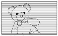
종래의 히스토그램 표시는 도 1a에 도시된 바와 같이, 이미지 전체에 대하여 밝기 정보를 표시하는 방법으로 히스토그램을 표시하였다. 즉, 히스토그램은 이미지 전체에서 해당하는 밝기의 픽셀의 개수를 화면에 표시하여 준다. 또한, DSLR과 고급 기종들은 도 1b에 도시된 바와 같이, 단순 밝기에서 R/G/B 픽셀의 각각의 밝기를 히스토그램으로 표시하기도 한다.In the conventional histogram display, as shown in FIG. 1A, a histogram is displayed by a method of displaying brightness information for the entire image. That is, the histogram displays the number of pixels of brightness corresponding to the entire image on the screen. In addition, the DSLR and high-end models also display the brightness of each of the R, G, and B pixels as a histogram in the simple brightness as shown in FIG. 1B.
기존의 히스토그램 또는 RGB 히스토그램 표시는 이미지 전체의 화면 밝기를 표시하기 때문에 각각 영역별 또는 위치별로의 밝기는 사람의 눈으로 직관적으로 판단을 해야만 한다. 또한, 이미지 전체에 대한 밝기를 히스토그램으로 표시하기 때문에, 사용자의 비관심 부분, 예를 들면 배경이 밝고, 사용자의 관심 부분, 예를 들면 사람의 얼굴은 어두운 경우에도 전체적인 히스토그램 표시는 적정한 범위 내로 표시될 수 있는 문제점이 있다.Since the conventional histogram or RGB histogram display displays the brightness of the entire image, the brightness of each region or position must be intuitively determined by the human eye. In addition, since the brightness of the whole image is displayed by the histogram, the histogram display is displayed in an appropriate range even when the user's uninteresting portion, for example, the background is bright and the user's interest, There is a problem.
본 발명은 상기 종래기술의 문제점을 해결하기 위해 안출된 것으로, 화면 전체에 대한 밝기 정도를 히스토그램으로 보여주는 것이 아니라, 각각의 수평 및 수직의 라인에 해당하는 휘도 정보를 화면에 표시해 줌으로써 이미지 전체의 휘도와 각각 위치 또는 영역별 휘도 정보를 직관적으로 파악할 수 있는 휘도 표시 방법 및 장치를 제공하는 데 목적이 있다.SUMMARY OF THE INVENTION The present invention has been made to solve the above problems of the prior art, and it is an object of the present invention to provide a display device and a method of displaying the brightness information of the entire image by displaying luminance information corresponding to each horizontal and vertical line, And a luminance display method and apparatus capable of intuitively grasping luminance information for each position or area.
또한, 이를 이용한 디지털 촬영 장치를 제공하는 데 다른 목적이 있다.Another object of the present invention is to provide a digital photographing apparatus using the same.
상기 기술적 과제를 달성하기 위한, 본 발명의 일 실시 예에 따른 휘도 표시 방법은 입력 영상의 휘도 성분을 기초로 수평축 및 수직축의 휘도 값을 각각 계산하는 단계; 상기 계산한 수평축 및 수직축의 휘도 값에 따라 수평 및 수직축의 히스토그램을 생성하는 단계; 및 상기 생성한 수평축 및 수직축의 히스토그램을 표시하도록 제어하는 단계를 포함한다.According to an aspect of the present invention, there is provided a luminance display method including: calculating luminance values of a horizontal axis and a vertical axis based on luminance components of an input image; Generating a histogram of horizontal and vertical axes according to the computed brightness values of the horizontal axis and the vertical axis; And controlling the display of the generated histogram of the horizontal axis and the vertical axis.
바람직하게, 상기 방법은 상기 수평축 및 수직축의 히스토그램에 대해 소정의 기준값 이상 및/또는 이하의 영역에 대해 상기 수평축과 수직축이 서로 교차하는 영역을 검색하는 단계를 더 포함하고, 상기 제어 단계는 상기 검색 결과에 따라 상기 입력 영상에서 고휘도 및/또는 저휘도 영역을 표시하도록 제어하는 것을 특징으로 한다.Preferably, the method further comprises the step of searching for a region where the horizontal axis and the vertical axis cross each other for a region above and / or below a predetermined reference value with respect to the histogram of the horizontal axis and the vertical axis, And to display a high luminance and / or low luminance region in the input image according to the result.
바람직하게, 상기 계산 단계는 상기 입력 영상의 각각의 픽셀에 대해 수평축 및 수직축으로 휘도 값의 합을 각각 계산하는 것을 특징으로 한다.Preferably, the calculating step calculates the sum of the luminance values on the horizontal axis and the vertical axis for each pixel of the input image.
바람직하게, 상기 계산 단계는 상기 입력 영상의 각각의 픽셀에 대해 수평축 및 수직축으로 휘도 값의 평균을 각각 계산하는 것을 특징으로 한다.Preferably, the calculating step calculates the average value of the luminance values on the horizontal axis and the vertical axis for each pixel of the input image.
바람직하게, 상기 제어 단계는 상기 고휘도 영역과 상기 저휘도 영역을 구분하여 표시하도록 제어하는 것을 특징으로 한다.Preferably, the control step controls to display the high luminance area and the low luminance area separately.
바람직하게, 상기 기준값은 히스토그램 상의 휘도 레벨에 대한 상한값 및/또는 하한값을 포함하는 것을 특징으로 한다.Preferably, the reference value includes an upper limit value and / or a lower limit value for the luminance level on the histogram.
바람직하게, 상기 제어 단계는 상기 수평축 및 수직축의 히스토그램이 상기 상한값 및/또는 하한값과의 차이값의 정도를 표시하도록 제어하는 것을 특징으로 한다.Preferably, the controlling step controls the histogram of the horizontal axis and the vertical axis to display the degree of difference between the upper limit value and the lower limit value.
바람직하게, 상기 입력 영상은 촬영하고자 하는 피사체의 프리뷰 영상 및 재생하고자 하는 영상 중 하나인 것을 특징으로 한다.Preferably, the input image is one of a preview image of a subject to be photographed and an image to be reproduced.
상기 다른 기술적 과제를 달성하기 위한, 본 발명의 다른 실시 예에 따른 휘도 표시 방법은 입력 영상의 휘도 성분을 기초로 상기 입력 영상의 임의의 축상으로 휘도 값을 계산하는 단계; 상기 계산한 휘도 값에 따라 상기 축상으로 히스토그램을 생성하는 단계; 및 상기 생성한 히스토그램을 표시하도록 제어하는 단계를 포함한다.According to another aspect of the present invention, there is provided a luminance display method including: calculating a luminance value on an arbitrary axis of an input image based on a luminance component of an input image; Generating a histogram on the axis according to the calculated luminance value; And controlling the display of the generated histogram.
바람직하게, 상기 계산 단계는 상기 축상으로 상기 입력 영상의 각각의 픽셀에 대한 휘도 값의 합 또는 평균을 계산하는 것을 특징으로 한다.Preferably, the calculating step calculates a sum or average of luminance values for each pixel of the input image on the axis.
상기 또 다른 기술적 과제를 달성하기 위한, 본 발명의 또 다른 실시 예에 따른 휘도 표시 장치는 입력 영상의 휘도 성분을 기초로 수평축의 휘도 값을 계산하는 수평축 휘도 계산부; 상기 입력 영상의 휘도 성분을 기초로 수직축의 휘도 값을 계산하는 수직축 휘도 계산부; 상기 계산한 수평축 및 수직축의 휘도 값에 따라 수평축 및 수직축의 히스토그램을 생성하는 히스토그램 생성부; 및 상기 생성한 수평축 및 수직축의 히스토그램을 표시하도록 제어하는 제어부를 포함한다.According to another aspect of the present invention, there is provided a luminance display apparatus including: a horizontal axis luminance calculation unit for calculating a luminance value of a horizontal axis based on a luminance component of an input image; A vertical axis luminance calculation unit for calculating a luminance value of a vertical axis based on a luminance component of the input image; A histogram generator for generating a histogram of the horizontal axis and the vertical axis according to the calculated luminance values of the horizontal axis and the vertical axis; And a controller for controlling the display of the generated histogram of the horizontal axis and the vertical axis.
바람직하게, 상기 제어부는 상기 수평축 및 수직축의 히스토그램에 대해 소정의 기준값 이상 및/또는 이하의 영역에 대해 상기 수평축과 수직축이 서로 교차하는 영역을 검색하고, 상기 검색 결과에 따라 상기 입력 영상에서 고휘도 및/또는 저휘도 영역을 표시하도록 제어하는 것을 특징으로 한다.Preferably, the control unit searches the histogram of the horizontal axis and the vertical axis for a region where the horizontal axis and the vertical axis cross each other with respect to a predetermined reference value and / or a region below the reference value, And / or a low-luminance area is displayed.
바람직하게, 상기 수평축 휘도 계산부 및 상기 수직축 휘도 계산부는 상기 입력 영상의 각각의 픽셀에 대해 수평축 및 수직축으로 휘도 값의 합을 각각 계산하는 것을 특징으로 한다.Preferably, the horizontal axis luminance calculation unit and the vertical axis luminance calculation unit calculate a sum of a luminance value on a horizontal axis and a vertical axis, respectively, for each pixel of the input image.
바람직하게, 상기 수평축 휘도 계산부 및 상기 수직축 휘도 계산부는 상기 입력 영상의 각각의 픽셀에 대해 수평축 및 수직축으로 휘도 값의 평균을 각각 계산하는 것을 특징으로 한다.Preferably, the horizontal axis luminance calculation unit and the vertical axis luminance calculation unit calculate the average of the luminance values on the horizontal axis and the vertical axis, respectively, for each pixel of the input image.
바람직하게, 상기 제어부는 상기 고휘도 영역과 상기 저휘도 영역을 구분하여 표시하도록 제어하는 것을 특징으로 한다.Preferably, the control unit controls to display the high luminance area and the low luminance area separately.
바람직하게, 상기 장치는 상기 기준값을 저장하는 기준값 저장부를 더 포함하고, 상기 기준값은 히스토그램 상의 휘도 레벨에 대한 상한값 및/또는 하한값을 포함하는 것을 특징으로 한다.Preferably, the apparatus further includes a reference value storing unit that stores the reference value, and the reference value includes an upper limit value and / or a lower limit value with respect to the brightness level on the histogram.
바람직하게, 상기 제어부는 상기 수평축 및 수직축의 히스토그램이 상기 상한값 및/또는 하한값과의 차이값의 정도를 표시하도록 제어하는 것을 특징으로 한다.Preferably, the control unit controls the histogram of the horizontal axis and the vertical axis to display the degree of difference between the upper limit value and the lower limit value.
바람직하게, 상기 입력 영상은 촬영하고자 하는 피사체의 프리뷰 영상 및 재생하고자 하는 영상인 것을 특징으로 한다.Preferably, the input image is a preview image of a subject to be photographed and an image to be reproduced.
상기 또 다른 기술적 과제를 달성하기 위한, 상기 방법을 컴퓨터에서 실행시키기 위한 프로그램을 기록한 기록매체를 포함한다.According to another aspect of the present invention, there is provided a recording medium on which a program for causing a computer to execute the method is recorded.
상기 또 다른 기술적 과제를 달성하기 위한, 상기 장치를 포함하는 디지털 촬영 장치를 포함한다.According to another aspect of the present invention, there is provided a digital photographing apparatus including the apparatus.
본 발명의 일 실시 예에 따른 휘도 표시 방법은 각각의 수평 및 수직의 라인에 해당하는 휘도 정보를 화면에 표시해 줌으로써 이미지 전체의 휘도와 각각 위치 또는 영역별 휘도 정보를 직관적으로 파악할 수 있는 효과가 있다.The luminance display method according to the embodiment of the present invention displays the luminance information corresponding to each horizontal and vertical line on the screen to thereby intuitively grasp the luminance of the entire image and the luminance information of each position or area .
이하, 첨부한 도면들을 참조하여 본 발명의 바람직한 실시 예들을 상세히 설명한다. 하기의 설명에서는 본 발명에 따른 동작을 이해하는데 필요한 부분만이 설명되며 그 이외 부분의 설명은 본 발명의 요지를 흩트리지 않도록 생략될 수 있다.Hereinafter, preferred embodiments of the present invention will be described in detail with reference to the accompanying drawings. In the following description, only parts necessary for understanding the operation according to the present invention will be described, and descriptions of other parts may be omitted so as not to disturb the gist of the present invention.
또한, 이하에서 설명되는 본 명세서 및 청구범위에 사용된 용어나 단어는 통상적이거나 사전적인 의미로 한정해서 해석되어서는 아니 되며, 본 발명을 가장 적 절하게 표현할 수 있도록 본 발명의 기술적 사상에 부합하는 의미와 개념으로 해석되어야 한다.It is also to be understood that the terms and words used in the following description and claims should not be construed as limited to ordinary or dictionary meanings and should not be construed as limiting the scope of the present invention, It should be interpreted as meaning and concept.
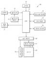
도 1은 본 발명의 일 실시 예에 따른 디지털 촬영 장치(100)의 블록도이다. 또한, 도 1과 함께 설명할 도 2는 상기 디지털 촬영 장치의 디지털 신호 처리부(70)를 설명하기 위한 블록도이다. 본 발명의 바람직한 실시 예에서는 디지털 촬영 장치에 한정하여 설명하지만, 이에 한정되지 않고 이미지를 재생하는 기능을 구비한 디지털 기기에 모두 동일하게 적용할 수 있음은 물론이다.1 is a block diagram of a
도 1에 도시된 바에 따르면, 디지털 촬영 장치(100)는 광학부(10), 광학 구동부(11), 촬상소자(15), 촬상소자 제어부(16), 조작부(20), 프로그램 저장부(30), 버퍼 저장부(40), 데이터 저장부(50), 표시 제어부(60), 데이터 구동부(61), 주사 구동부(63), 표시부(65) 및 디지털 신호 처리부(DSP, 70)를 포함한다.1, the
광학부(10)는 피사체로부터의 광학 신호가 입력되어 촬상 소자(13)로 제공한다. 광학부(10)는 초점 거리(focal length)에 따라 화각이 좁아지거나 또는 넓어지도록 제어하는 줌 렌즈 및 피사체의 초점을 맞추는 포커스 렌즈 등 적어도 하나의 렌즈를 포함할 수 있다. 또한, 광학부(10)는 광량을 조절하는 조리개를 더 포함할 수 있다.The
광학 구동부(11)는 렌즈의 위치, 조리개의 개폐 등을 조절한다. 렌즈의 위치를 이동시켜 초점을 맞출 수 있다. 또한, 조리개의 개폐를 조절하여 광량을 조절할 수 있다. 실시간으로 입력되는 영상 신호에 의해 자동으로 생성되는 제어 신호 또는 사용자의 조작에 의해 수동으로 입력되는 제어 신호에 따라 광학 구동 부(11)가 광학부(10)를 제어할 수 있다.The
광학부(10)를 투과한 광학 신호는 촬상 소자(15)의 수광면에 이르러 피사체의 상을 결상한다. 촬상 소자(15)는 광학 신호를 전기 신호로 변환하는 CCD(Charge Coupled Device) 또는 CIS(Complementary Metal Oxide Semiconductor Image Sensor) 등을 사용할 수 있다. 이와 같은 촬상소자(15)는 촬상소자 제어부(16)에 의해 감도 등이 조절될 수 있다. 촬상소자 제어부(16)도 실시간으로 입력되는 영상 신호에 의해 자동으로 생성되는 제어 신호 또는 사용자의 조작에 의해 수동으로 입력되는 제어 신호에 따라 촬상소자(15)를 제어할 수 있다.The optical signal transmitted through the
조작부(20)는 사용자 등의 외부로부터의 제어 신호를 입력할 수 있는 곳이다. 조작부(20)는 정해진 시간 동안 촬상 소자(15)를 빛에 노출하여 사진을 촬영하는 셔터-릴리즈 신호를 입력하는 셔터-릴리즈 버튼, 전원을 공급하기 위해 입력하는 전원 버튼, 입력에 따라 화각을 넓어지게 하거나 화각을 좁아지게 하는 광각-줌 버튼 및 망원-줌 버튼과, 문자 입력 또는 촬영 모드, 재생 모드 등의 모드 선택, 화이트 밸런스 설정 기능 선택, 노출 설정 기능 선택 등의 다양한 기능 버튼들이 있다. 본 발명의 바람직한 실시 예에서, 사용자는 조작부(20)를 통해 프리뷰 영상 또는 재생 영상을 표시부(65)에 표시하고 나서, 휘도 히스토그램을 표시하기 위한 히스토그램 표시를 선택할 수 있다. 또한, 사용자의 조작부(20)를 통한 메뉴 선택에 따라 수평축과 수직축으로의 휘도 히스토그램 표시와 함께 고휘도 영역 또는 저휘도 영역도 표시할 수 있으며, 기준 휘도 값의 상한값과 하한값과의 차이의 정도도 표시할 수 있다.The
조작부(20)는 상기와 같이 다양한 버튼의 형태를 가질 수도 있지만, 이에 한정되는 것은 아니며, 키보드, 터치 패드, 터치 스크린, 리모트 컨트롤러 등과 같이 사용자가 입력할 수 있는 어떠한 형태로 구현되어도 무방하다.The
또한, 디지털 촬영 장치(100)는 이를 구동하는 운영 시스템, 응용 시스템 등의 프로그램을 저장하는 프로그램 저장부(30), 연산 수행 중에 필요한 데이터 또는 결과 데이터들을 임시로 저장하는 버퍼 저장부(40), 영상 신호를 포함하는 이미지 파일을 비롯하여 프로그램에 필요한 다양한 정보들을 저장하는 데이터 저장부(50)를 포함한다.The
아울러, 디지털 촬영 장치(100)는 이의 동작 상태 또는 디지털 촬영 장치(100)에서 촬영한 이미지 정보를 표시하도록 제어하는 표시 제어부(60), 표시 제어부(60)로부터 입력되어 표시 데이터를 전달하는 데이터 구동부(61)와 주사 구동부(63), 데이터 구동부(61)와 주사 구동부(63)로부터 입력되는 신호에 따라 소정 영상을 표시하는 표시부(65)를 포함한다. 표시부(65)는 액정 디스플레이 패널(LCD), 유기 발광 디스플레이 패널(OLED), 전기 영동 디스플레이 패널(EDD) 등으로 이루어질 수 있다.In addition, the
그리고 디지털 촬영 장치(100)는 입력되는 영상 신호를 처리하고, 이에 따라 또는 외부 입력 신호에 따라 각 구성부들을 제어하는 디지털 신호 처리부(70)를 포함한다.The
디지털 신호 처리부(70)에 관하여 도 2를 함께 참조하여 설명한다.The digital
도 2를 참조하면, 디지털 신호 처리부(70)는 제어부(71), 영상 신호 처리 부(72), 수평축 휘도 계산부(73), 수직축 휘도 계산부(74), 히스토그램 생성부(75), 기준값 저장부(76)를 포함한다. 이하, 디지털 신호 처리(70)와 특허청구범위에서 사용된 휘도 표시 장치는 동일한 의미로 이해되어야 한다.2, the digital
제어부(71)는 디지털 신호 처리부(70)의 전반적인 동작을 제어한다.The
영상 신호 처리부(72)는 촬상 소자(15)로부터 입력된 영상 신호를 디지털 신호로 변환하고, 사람의 시각에 맞게 영상 신호를 변환하도록 감마 컬렉션(Gamma Correction), 색필터 배열보간(color filter array interpolation), 색 매트릭스(color matrix), 색보정(color correction), 색 향상(color enhancement) 등의 영상 신호 처리를 수행한다. 또한, 영상 신호 처리부(72)는 그 기능이 설정된 경우 오토화이트밸런스(Auto White Balance)나 오토익스포저(Auto Exposure) 알고리즘을 수행할 수 있다. 또한, 영상 데이터를 스케일러를 이용하여 그 크기를 조절하며, 압축하여 소정 형식의 이미지 파일을 형성한다. 반대로 이미지 파일의 압축을 해제하기도 한다. 영상 신호 처리부(72)는 사진 촬영 전 라이브-뷰 모드에서 실시간으로 입력되는 영상 신호와 셔터-릴리즈 신호에 의해 입력된 영상 신호에 대해 상기와 같은 영상 신호 처리들을 행할 수 있다. 이때, 상기 영상 신호들 각각에 대해 다른 영상 신호 처리가 행해질 수 있다.The image
본 발명의 바람직한 실시 예에서, 영상 신호 처리부(72)는 촬상 소자(15), 예를 들면 CCD를 통해 입력된 RGB 영상 신호 또는 데이터 저장부(50)로부터 읽어들인 이미지 데이터를 휘도/색도 신호로 변환하여 변환한 휘도 신호를 수평축 휘도 계산부(73)와 수직축 휘도 계산부(74)에 제공한다.In the preferred embodiment of the present invention, the image
수평축 휘도 계산부(73)는 영상 신호 처리부(72)를 통해 입력된 영상의 휘도 성분을 기초로 수평축의 휘도 값을 계산한다.The horizontal axis
수직축 휘도 계산부(74)는 영상 신호 처리부(72)를 통해 입력된 영상의 휘도 성분을 기초로 수직축의 휘도 값을 계산한다.The vertical axis
여기서, 휘도 값은 입력된 영상의 각각의 픽셀에 대해 수평축과 수직축으로 휘도를 합한 값 또는 수평축과 수직축으로 휘도를 평균한 값을 의미한다. 예를 들면 8bit의 픽셀 데이터의 경우에 0~255까지의 휘도 값을 합하거나 이러한 값들을 평균하여 계산한다. 또한, 0~255까지의 휘도 값을 0~100까지의 값으로 환산하여 계산할 수도 있다.Here, the luminance value means a value obtained by adding the luminance to the horizontal axis and the vertical axis for each pixel of the input image, or averaging the luminance along the horizontal axis and the vertical axis. For example, in the case of 8-bit pixel data, the luminance values from 0 to 255 are summed or averaged and calculated. It is also possible to calculate the luminance value from 0 to 255 by converting the luminance value into a value from 0 to 100.
수평축과 수직축으로의 휘도 값 계산은 도 4a 내지 4b를 참조하여 설명한다. 도 4a에는 입력 영상, 예를 들면 4×4 영상의 각각의 픽셀의 휘도값이 도시되어 있다.Calculation of the luminance values on the horizontal axis and the vertical axis will be described with reference to Figs. 4A to 4B. 4A shows luminance values of respective pixels of an input image, for example, a 4x4 image.
도 4b에 도시된 것과 같이, 종래의 히스토그램 표시에서는 가로축은 밝기를 나타내고, 세로축은 해당하는 밝기의 픽셀 개수를 나타낸다. 따라서, 도 4a에 도시된 전체 영상에서 밝기 1에 해당하는 픽셀의 개수를 계산하면 8개이고, 밝기 2에 해당하는 픽셀의 개수를 계산하면 3개, 밝기 3에 해당하는 픽셀의 개수는 0개, 밝기 4에 해당하는 픽셀의 개수는 3개, 밝기 5에 해당하는 픽셀의 개수는 2개이다. 따라서, 종래기술에 따른 히스토그램은 도 4b에 도시된 것과 같은 분포를 나타낸다.As shown in FIG. 4B, in the conventional histogram display, the horizontal axis represents the brightness and the vertical axis represents the number of pixels of the corresponding brightness. 4A, the number of pixels corresponding to
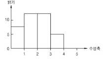
도 4c는 수평축 휘도 계산부(73)가 휘도 히스토그램 표시를 위한 휘도값 계 산을 설명하기 위한 도면이다.4C is a diagram for explaining the calculation of the luminance value for displaying the luminance histogram by the horizontal axis
도 4c를 참조하면, 도 4a에 도시된 입력 영상에 대해 수평축으로 각각의 픽셀의 휘도 값을 수평축으로 계산한 히스토그램이 도시되어 있다. 가로축이 수평축이고 세로가 휘도값이다. 도 4a에서 첫번째 수평축의 픽셀들의 휘도 값들을 모두 합하면 휘도값은 7이고, 두번째 수평축의 픽셀들의 휘도값들을 모두 합하면 휘도값은 12이고, 세번째 수평축의 픽셀들의 휘도값은 12이고, 네번째 수평축의 휘도값은 5이다.Referring to FIG. 4C, there is shown a histogram in which the luminance value of each pixel is calculated on the horizontal axis with respect to the input image shown in FIG. 4A on the horizontal axis. The horizontal axis is the horizontal axis and the vertical is the luminance value. 4A, the luminance value is 7, the luminance value is 12, the luminance value of the pixels of the third horizontal axis is 12, the luminance value of the fourth horizontal axis is 12, The value is 5.
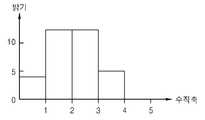
도 4d를 참조하면, 도 4a에 도시된 입력 영상에 대해 수직축으로 각각의 픽셀의 휘도 값을 수직축으로계산한 히스토그램이 도시되어 있다. 가로축이 수직축고 세로축이 휘도값이다. 도 4a에서 첫번째 수직축의 픽셀들의 휘도 값들을 모두 합하면 휘도값은 4이고, 두번째 수직축의 픽셀들의 휘도값들을 모두 합하면 휘도값은 13이고, 세번째 수직축의 픽셀들의 휘도값은 13이고, 네번째 수평축의 휘도값은 6이다.Referring to FIG. 4D, there is shown a histogram in which the luminance values of the respective pixels are calculated on the vertical axis with respect to the input image shown in FIG. 4A on the vertical axis. The horizontal axis is the vertical axis and the vertical axis is the luminance value. 4A, when the luminance values of the pixels of the first vertical axis are all summed, the luminance value is 4. When the luminance values of the pixels of the second vertical axis are all summed, the luminance value is 13, the luminance value of the pixels of the third vertical axis is 13, The value is 6.
이상과 같이, 수평축 휘도 계산부(73)와 수직축 휘도 계산부(74)는 입력 영상의 각각의 픽셀들의 수평축 방향과 수직축 방향으로 휘도값들을 계산한다. 여기서, 픽셀 단위로 계산하는 것을 설명하였지만, 픽셀들의 집합인 블록단위로 계산할 수도 있다. 또한, 픽셀들의 휘도값의 합을 계산하는 것으로 설명하였지만, 픽셀들의 평균 휘도 값을 계산할 수도 있다. 또한, 수평축 휘도 계산부(73)와 수직축 휘도 계산부(74)를 분리하여 설명하였지만, 통합된 휘도 계산부에서 수평축과 수직축의 휘도 계산을 수행할 수 있음은 물론이다. 또한, 수평축과 수직축으로 휘도 값 의 합 또는 평균을 각각 계산하는 것을 설명하였지만, 임의의 축, 수평축 또는 수직축상으로 휘도 값의 합 또는 평균을 계산하고, 이에 따른 수평축 또는 수직축 히스토그램을 생성하여 어느 하나의 축에 대한 히스토그램만을 표시해 줄 수도 있다.As described above, the horizontal axis
히스토그램 생성부(75)는 수평축 휘도 계산부(73)와 수직축 휘도 계산부(74)에서 계산한 수평축과 수직축의 휘도 값에 따라 수평축과 수직축의 히스토그램을 생성한다. 제어부(71)는 히스토그램 생성부(75)에서 생성한 수평축 및 수직축의 히스토그램을 표시부(65)에 표시하도록 제어한다.The
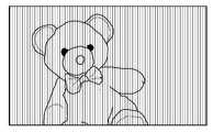
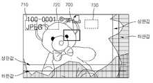
도 5a 내지 5c에는 수평축과 수직축에 대한 휘도 값 계산과 휘도 히스토그램을 표시한 것이 도시되어 있다. 도 5a와 도 5b에 도시된 것처럼, 수평축 방향과 수직축 방향으로 휘도 값들을 계산하고, 도 5c에 도시된 것처럼, 계산한 휘도값들을 히스토그램으로 생성하여 표시 화면 하단과 표시 화면 우측단에 각각 표시한다. 또한, 도 5a에 도시된 바와 같이, 수평축상으로 휘도값 계산 또는 도 5b에 도시된 바와 같이, 수직축상으로 휘도값 계산을 선택적으로 수행하여 어느 하나에 대한 히스토그램을 생성하여 입력 영상과 함께 또는 분리하여 표시해 줄 수도 있다.5A to 5C show calculation of the luminance value for the horizontal and vertical axes and display of the luminance histogram. As shown in FIGS. 5A and 5B, luminance values are calculated in the horizontal axis direction and the vertical axis direction, and the calculated luminance values are generated as a histogram and displayed at the lower end of the display screen and the right end of the display screen, respectively, as shown in FIG. 5C . In addition, as shown in FIG. 5A, a luminance value calculation on a horizontal axis or a luminance value calculation on a vertical axis is selectively performed as shown in FIG. 5B to generate a histogram for either one, And display it.
제어부(71)는 도 5c에 도시되어 있는 수평축 및 수직축의 히스토그램에 대해 소정의 기준값 이상인 영역과 소정의 기준값 이하의 영역에 대해 표시 화면 하단의 수평축 히스토그램과 표시 화면 우측단의 수직축 히스토그램이 수평축과 수직축 상으로 서로 교차하는 영역을 검색한다. 이러한 검색이 도 6에 도시되어 있다. 또한, 검색 결과에 따라 입력 영상에서 고휘도 영역과 저휘도 영역을 표시하도록 제어한다.5C, the horizontal axis histogram at the lower end of the display screen and the vertical axis histogram at the right end of the display screen are displayed on the horizontal axis and the vertical axis on the vertical axis To search for areas crossing each other. Such a search is shown in Fig. In addition, control is performed to display a high luminance area and a low luminance area in the input image according to the search result.
도 6을 참조하면, 표시 화면 하단의 수평축 휘도 히스토그램에서 상한값 이상인 영역과 표시 화면 우측단의 수직축 휘도 히스토그램에서 상한값 이상인 영역에 대해 수직축과 수평축 상으로 교차하는 영역(600,700)을 검색한다. 또한, 표시 화면 하단의 수평축 휘도 히스토그램에서 하한값 이하인 영역과 표시 화면 우측단의 수직축 휘도 히스토그램에서 하한값 이하인 영역에 대해 수직축과 수평축 상으로 교차하는 영역(610,620,630)을 검색한다. 여기서, 상한값과 하한값은 휘도 레벨의 적정범위를 정하는 기준으로서 임의로 결정할 수 있다.Referring to FIG. 6,
기준값 저장부(76)는 적정한 휘도 레벨에 대한 기준값을 저장하고 있으며, 기준값은 적정 휘도 레벨의 상한값과 적정 휘도 레벨의 하한값을 포함한다. 이러한 상한값과 하한값은 촬영하고자 하는 장면 모드, 예를 들면 인물 모드, 장면 모드, 야경 모드 등에 따라 다르게 설정되는 것이 바람직하며, 사용자의 선택에 따라 설정될 수도 있다.The reference
도 7을 참조하면, 제어부(71)는 실선으로 표시된 교차 영역(700)은 고휘도 영역으로 표시하고, 점선으로 표시된 교차 영역들(710,720,730)은 저휘도 영역으로 표시하도록 제어한다.Referring to FIG. 7, the
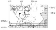
도 8을 참조하면, 제어부(71)는 실선으로 표시된 교차 영역(800)은 고휘도 영역으로 표시하고, 점선으로 표시된 교차 영역들(810,820,830)은 저휘도 영역으로 표시하도록 제어함과 동시에, 기준값인 상한값과 하한값과의 차이값의 정도를 표시하여 사용자로 하여금 어느 정도 차이가 나는지를 직관적으로 알 수 있도록 해 줄수 있다.8, the
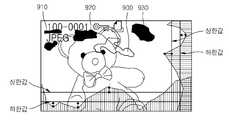
도 9을 참조하면, 고휘도 영역(900)에 해당하는 부분과 저휘도 영역(910,920,930)에 해당하는 부분들을 각각 흰색 영역 및 검은색 영역으로 표시해 줄 수 있다.Referring to FIG. 9, portions corresponding to the
도 10은 본 발명의 또 다른 실시 예에 따른 휘도 표시 방법을 설명하기 위한 흐름도이다.10 is a flowchart for explaining a luminance display method according to another embodiment of the present invention.
도 10을 참조하면, 단계 1000에서, 입력 영상의 수평축 휘도값을 계산한다. 단계 1002에서, 입력 영상의 수직축 휘도값을 계산한다. 단계 1000과 단계 1002는 동시에 수행할 수도 있으며, 역으로 수행할 수도 있으며 그 순서에 한정되지 않는다.Referring to FIG. 10, in
단계 1004에서, 수평축 및 수직축 휘도값을 이용하여 입력 영상의 휘도 분포를 검색한다. 즉, 계산한 수평축 및 수직축의 휘도 값에 따라 수평 및 수직축의 히스토그램을 생성하고, 수평축 히스토그램과 수직축 히스토그램이 서로 교차하는 영역을 검색함으로써 입력 영상의 휘도 분포를 검색한다.In
단계 1006에서, 입력 영상의 고휘도 및 저휘도 영역을 표시한다. 고휘도 영역과 저휘도 영역을 구별하여 표시해 줄 수 있다.In
도 11은 본 발명의 또 다른 실시 예에 따른 휘도 표시 방법을 설명하기 위한 도면이다.11 is a view for explaining a luminance display method according to another embodiment of the present invention.
도 11을 참조하면, 단계 1100에서, 입력 영상의 수평 및 수직축 휘도값을 계산한다. 단계 1102에서, 수평 및 수직축 휘도값을 이용하여 입력 영상의 휘도 분포를 검색한다. 단계 1104에서, 입력 영상의 고휘도 영역과 저휘도 영역을 표시한 다. 단계 1106에서, 고휘도 및 저휘도 영역의 휘도값과 기준 휘도값을 비교하고, 단계 1108에서, 비교 결과를 표시한다. 즉, 적정 휘도 범위를 나타내는 기준값과 현재 영상의 고휘도 영역의 휘도값 및 저휘도 영역의 휘도값의 차이값의 정도를 표시함으로써 사용자로 하여금 현재 휘도 분포 및 정도를 직관적으로 알 수 있게 한다.Referring to FIG. 11, in step 1100, the horizontal and vertical axis luminance values of the input image are calculated. In
전술한 실시 예들은 본 발명이 적용될 수 있는 디지털 촬영 장치의 일예로서 디지털 카메라를 중심으로 기술하였으나, 이에 한정하는 것은 아니다. 당업자라면 본 발명이 카메라 기능이 부가된 카메라폰, PDA(personal digital assistant), PMP(portable multimedia player)에도 적용될 수 있음을 이해할 것이다.Although the embodiments described above are based on a digital camera as an example of a digital photographing apparatus to which the present invention can be applied, the present invention is not limited thereto. Those skilled in the art will appreciate that the present invention is also applicable to a camera phone, a personal digital assistant (PDA), and a portable multimedia player (PMP) with a camera function.
한편, 본 발명은 컴퓨터로 읽을 수 있는 기록 매체에 컴퓨터가 읽을 수 있는 코드로 구현하는 것이 가능하다. 컴퓨터가 읽을 수 있는 기록 매체는 컴퓨터 시스템에 의하여 읽혀질 수 있는 데이터가 저장되는 모든 종류의 기록 장치를 포함한다.Meanwhile, the present invention can be embodied in computer readable code on a computer readable recording medium. A computer-readable recording medium includes all kinds of recording apparatuses in which data that can be read by a computer system is stored.
컴퓨터가 읽을 수 있는 기록 매체의 예로는 ROM, RAM, CD-ROM, 자기 테이프, 플로피디스크, 광 데이터 저장장치 등이 있으며, 또한 캐리어 웨이브(예를 들어 인터넷을 통한 전송)의 형태로 구현하는 것을 포함한다. 또한, 컴퓨터가 읽을 수 있는 기록 매체는 네트워크로 연결된 컴퓨터 시스템에 분산되어, 분산 방식으로 컴퓨터가 읽을 수 있는 코드가 저장되고 실행될 수 있다. 그리고 본 발명을 구현하기 위한 기능적인(functional) 프로그램, 코드 및 코드 세그먼트들은 본 발명이 속하는 기술 분야의 프로그래머들에 의하여 용이하게 추론될 수 있다.Examples of the computer-readable recording medium include a ROM, a RAM, a CD-ROM, a magnetic tape, a floppy disk, an optical data storage device and the like, and also a carrier wave (for example, transmission via the Internet) . In addition, the computer-readable recording medium may be distributed over network-connected computer systems so that computer readable codes can be stored and executed in a distributed manner. In addition, functional programs, codes, and code segments for implementing the present invention can be easily deduced by programmers skilled in the art to which the present invention belongs.
이제까지 본 발명에 대하여 바람직한 실시 예를 중심으로 살펴보았다. 본 발명이 속하는 기술 분야에서 통상의 지식을 가진 자는 본 발명의 본질적인 특성에서 벗어나지 않는 범위에서 변형된 형태로 본 발명을 구현할 수 있음을 이해할 것이다. 그러므로 상기 개시된 실시 예들은 한정적인 관점이 아니라 설명적인 관점에서 고려되어야 한다. 본 발명의 범위는 전술한 설명이 아니라 특허청구범위에 나타나 있으며, 그와 동등한 범위 내에 있는 모든 차이점은 본 발명에 포함된 것으로 해석되어야 한다.The present invention has been described above with reference to preferred embodiments. It will be understood by those skilled in the art that the present invention may be embodied in various other forms without departing from the spirit or essential characteristics thereof. Therefore, the above-described embodiments should be considered in an illustrative rather than a restrictive sense. The scope of the present invention is indicated by the appended claims rather than by the foregoing description, and all differences within the scope of equivalents thereof should be construed as being included in the present invention.
도 1a 및 1b는 종래의 피사체의 휘도 히스토그램을 표시하는 것을 설명하기 위한 도면이다.Figs. 1A and 1B are diagrams for explaining display of a luminance histogram of a conventional subject. Fig.
도 2는 본 발명의 일 실시 예에 따른 디지털 촬영 장치(100)의 개략적인 블록도이다.2 is a schematic block diagram of a digital photographing
도 3은 도 2에 도시된 디지털 신호 처리부(70)의 개략적인 블록도이다.3 is a schematic block diagram of the digital
도 4a 내지 4b는 종래기술과 구별되는 본 발명의 다른 실시 예에 따른 휘도 히스토그램 계산 방법을 설명하기 위한 도면이다.4A and 4B are views for explaining a method of calculating a luminance histogram according to another embodiment of the present invention, which is different from the conventional art.
도 5a 내지 5c는 본 발명의 또 다른 실시 예에 따른 피사체의 휘도 히스토그램을 표시하는 것을 설명하기 위한 도면이다.5A to 5C are views for explaining display of a luminance histogram of a subject according to another embodiment of the present invention.
도 6은 본 발명의 또 다른 실시 예에 따른 휘도 표시 예를 설명하기 위한 도면이다.6 is a view for explaining an example of a luminance display according to another embodiment of the present invention.
도 7은 본 발명의 또 다른 실시 예에 따른 휘도 표시 예를 설명하기 위한 도면이다.7 is a view for explaining an example of a luminance display according to another embodiment of the present invention.
도 8은 본 발명의 또 다른 실시 예에 따른 휘도 표시 예를 설명하기 위한 도면이다.8 is a view for explaining an example of a luminance display according to another embodiment of the present invention.
도 9는 본 발명의 또 다른 실시 예에 따른 휘도 표시 예를 설명하기 위한 도면이다.9 is a view for explaining an example of a luminance display according to another embodiment of the present invention.
도 10은 본 발명의 또 다른 실시 예에 따른 휘도 표시 방법을 설명하기 위한 흐름도이다.10 is a flowchart for explaining a luminance display method according to another embodiment of the present invention.
도 11은 본 발명의 또 다른 실시 예에 따른 휘도 표시 방법을 설명하기 위한 도면이다.11 is a view for explaining a luminance display method according to another embodiment of the present invention.
<도면의 주요 부분에 대한 부호의 설명>Description of the Related Art
100: 디지털 촬영 장치 70: 디지털 신호 처리부100: Digital photographing apparatus 70: Digital signal processor
71: 제어부 72: 영상 신호 처리부71: control unit 72: video signal processing unit
73: 수평축 휘도 계산부 74: 수직축 휘도 계산부73: horizontal axis luminance calculation unit 74: vertical axis luminance calculation unit
75: 히스토그램 생성부 76: 기준값 저장부75: histogram generator 76: reference value storage
Claims (20)
Translated fromKoreanPriority Applications (2)
| Application Number | Priority Date | Filing Date | Title |
|---|---|---|---|
| KR1020080115805AKR101571331B1 (en) | 2008-11-20 | 2008-11-20 | Brightness display method and apparatus, and digital photographing apparatus using the same |
| US12/620,661US8339498B2 (en) | 2008-11-20 | 2009-11-18 | Method and apparatus for displaying luminance, and digital photographing apparatus using the same |
Applications Claiming Priority (1)
| Application Number | Priority Date | Filing Date | Title |
|---|---|---|---|
| KR1020080115805AKR101571331B1 (en) | 2008-11-20 | 2008-11-20 | Brightness display method and apparatus, and digital photographing apparatus using the same |
Publications (2)
| Publication Number | Publication Date |
|---|---|
| KR20100056817A KR20100056817A (en) | 2010-05-28 |
| KR101571331B1true KR101571331B1 (en) | 2015-11-24 |
Family
ID=42230630
Family Applications (1)
| Application Number | Title | Priority Date | Filing Date |
|---|---|---|---|
| KR1020080115805AExpired - Fee RelatedKR101571331B1 (en) | 2008-11-20 | 2008-11-20 | Brightness display method and apparatus, and digital photographing apparatus using the same |
Country Status (2)
| Country | Link |
|---|---|
| US (1) | US8339498B2 (en) |
| KR (1) | KR101571331B1 (en) |
Families Citing this family (3)
| Publication number | Priority date | Publication date | Assignee | Title |
|---|---|---|---|---|
| KR101839473B1 (en)* | 2011-08-03 | 2018-03-19 | 삼성전자주식회사 | Method for providing reference image and image photographing device thereof |
| KR102245366B1 (en)* | 2014-10-27 | 2021-04-28 | 엘지전자 주식회사 | Digital device and method for controlling the same |
| CN113114930B (en)* | 2021-03-26 | 2022-10-04 | 维沃移动通信(杭州)有限公司 | Information display method, device, equipment and medium |
Citations (1)
| Publication number | Priority date | Publication date | Assignee | Title |
|---|---|---|---|---|
| JP2007325065A (en) | 2006-06-02 | 2007-12-13 | New Industry Research Organization | Photography navigation program, and photography navigation system |
Family Cites Families (13)
| Publication number | Priority date | Publication date | Assignee | Title |
|---|---|---|---|---|
| US5150432A (en)* | 1990-03-26 | 1992-09-22 | Kabushiki Kaisha Toshiba | Apparatus for encoding/decoding video signals to improve quality of a specific region |
| US5412578A (en)* | 1992-10-30 | 1995-05-02 | Hitachi, Ltd. | Method and device for pattern form recognition and automatic pattern match cutting device |
| US7650015B2 (en)* | 1997-07-22 | 2010-01-19 | Image Processing Technologies. LLC | Image processing method |
| US6738527B2 (en)* | 1997-06-09 | 2004-05-18 | Seiko Epson Corporation | Image processing apparatus, an image processing method, a medium on which an image processing control program is recorded, an image evaluation device, and image evaluation method and a medium on which an image evaluation program is recorded |
| JPH1166320A (en)* | 1997-08-12 | 1999-03-09 | Mitsubishi Electric Corp | Eye image tracking device |
| US7027500B1 (en)* | 2000-12-12 | 2006-04-11 | Ati Research, Inc. | Linear prediction based initialization of a single-axis blind equalizer for VSB signals |
| JP4167097B2 (en)* | 2003-03-17 | 2008-10-15 | 株式会社沖データ | Image processing method and image processing apparatus |
| JP4366318B2 (en)* | 2005-01-11 | 2009-11-18 | キヤノン株式会社 | Image processing apparatus and method, and program |
| JP2006260397A (en)* | 2005-03-18 | 2006-09-28 | Konica Minolta Holdings Inc | Eye opening degree estimating device |
| US7804980B2 (en)* | 2005-08-24 | 2010-09-28 | Denso Corporation | Environment recognition device |
| KR100727390B1 (en)* | 2005-12-26 | 2007-06-12 | 삼성전자주식회사 | Adaptive Image Size Inverter and Its Image Size Conversion Method |
| JP4535114B2 (en)* | 2007-10-26 | 2010-09-01 | ソニー株式会社 | Imaging apparatus and imaging method, display control apparatus and display control method, and program |
| US20090135935A1 (en)* | 2007-11-28 | 2009-05-28 | Legend Silicon Corp | Digital tv receiver having built-in diversity structure |
- 2008
- 2008-11-20KRKR1020080115805Apatent/KR101571331B1/ennot_activeExpired - Fee Related
- 2009
- 2009-11-18USUS12/620,661patent/US8339498B2/ennot_activeExpired - Fee Related
Patent Citations (1)
| Publication number | Priority date | Publication date | Assignee | Title |
|---|---|---|---|---|
| JP2007325065A (en) | 2006-06-02 | 2007-12-13 | New Industry Research Organization | Photography navigation program, and photography navigation system |
Also Published As
| Publication number | Publication date |
|---|---|
| US8339498B2 (en) | 2012-12-25 |
| US20100141797A1 (en) | 2010-06-10 |
| KR20100056817A (en) | 2010-05-28 |
Similar Documents
| Publication | Publication Date | Title |
|---|---|---|
| US8937677B2 (en) | Digital photographing apparatus, method of controlling the same, and computer-readable medium | |
| JP4872797B2 (en) | Imaging apparatus, imaging method, and imaging program | |
| KR101594292B1 (en) | Digital imaging device, digital imaging device control method, and computer readable storage medium | |
| KR101643602B1 (en) | Method and apparatus for guiding composition, and digital photographing apparatus | |
| JP5624809B2 (en) | Image signal processing device | |
| JP6317577B2 (en) | Video signal processing apparatus and control method thereof | |
| KR101700366B1 (en) | Digital photographing apparatus and control method thereof | |
| KR20100055938A (en) | Method and apparatus for displaying scene information, and digital photographing apparatus thereof | |
| US20100033614A1 (en) | Method of controlling digital image processing apparatus, medium for recording the method, and digital image processing apparatus operating according to the method | |
| KR101571331B1 (en) | Brightness display method and apparatus, and digital photographing apparatus using the same | |
| KR20100099008A (en) | Auto focusing method and apparatus, and digital photographing apparatus using thereof | |
| US8456551B2 (en) | Photographing apparatus and smear correction method thereof | |
| KR101812656B1 (en) | Digital photographing apparatus and control method thereof | |
| KR20110090098A (en) | Digital image processing device and control method thereof | |
| KR101605769B1 (en) | Image processing method and apparatus, and digital photographing apparatus using thereof | |
| KR101960508B1 (en) | Display apparatus and method | |
| KR20110060299A (en) | Digital photographing apparatus, control method thereof, and computer readable medium | |
| KR101477533B1 (en) | Method and apparatus for compensating an image | |
| KR101416236B1 (en) | Digital photographing apparatus for automatically performing auto focusing and control method thereof | |
| CN112422809B (en) | Image pickup apparatus, control method of image pickup apparatus, and computer readable medium | |
| KR101448539B1 (en) | Image processing method and apparatus, and digital photographing apparatus using thereof | |
| KR101436838B1 (en) | Method and apparatus for processing auto focusing information, and digital photographing apparatus using the same | |
| KR20100096494A (en) | White ballance control method and apparatus using a flash, and digital photographing apparatus using thereof | |
| JP2004179708A (en) | Digital camera and control method therefor | |
| KR101581219B1 (en) | Method and apparatus for processing auto-focusing information and digital photographing apparatus using thereof |
Legal Events
| Date | Code | Title | Description |
|---|---|---|---|
| PA0109 | Patent application | St.27 status event code:A-0-1-A10-A12-nap-PA0109 | |
| N231 | Notification of change of applicant | ||
| PN2301 | Change of applicant | St.27 status event code:A-3-3-R10-R13-asn-PN2301 St.27 status event code:A-3-3-R10-R11-asn-PN2301 | |
| N231 | Notification of change of applicant | ||
| PN2301 | Change of applicant | St.27 status event code:A-3-3-R10-R13-asn-PN2301 St.27 status event code:A-3-3-R10-R11-asn-PN2301 | |
| PG1501 | Laying open of application | St.27 status event code:A-1-1-Q10-Q12-nap-PG1501 | |
| R18-X000 | Changes to party contact information recorded | St.27 status event code:A-3-3-R10-R18-oth-X000 | |
| A201 | Request for examination | ||
| PA0201 | Request for examination | St.27 status event code:A-1-2-D10-D11-exm-PA0201 | |
| E902 | Notification of reason for refusal | ||
| PE0902 | Notice of grounds for rejection | St.27 status event code:A-1-2-D10-D21-exm-PE0902 | |
| P11-X000 | Amendment of application requested | St.27 status event code:A-2-2-P10-P11-nap-X000 | |
| P13-X000 | Application amended | St.27 status event code:A-2-2-P10-P13-nap-X000 | |
| E902 | Notification of reason for refusal | ||
| PE0902 | Notice of grounds for rejection | St.27 status event code:A-1-2-D10-D21-exm-PE0902 | |
| E13-X000 | Pre-grant limitation requested | St.27 status event code:A-2-3-E10-E13-lim-X000 | |
| P11-X000 | Amendment of application requested | St.27 status event code:A-2-2-P10-P11-nap-X000 | |
| P13-X000 | Application amended | St.27 status event code:A-2-2-P10-P13-nap-X000 | |
| E701 | Decision to grant or registration of patent right | ||
| PE0701 | Decision of registration | St.27 status event code:A-1-2-D10-D22-exm-PE0701 | |
| GRNT | Written decision to grant | ||
| PR0701 | Registration of establishment | St.27 status event code:A-2-4-F10-F11-exm-PR0701 | |
| PR1002 | Payment of registration fee | St.27 status event code:A-2-2-U10-U11-oth-PR1002 Fee payment year number:1 | |
| PG1601 | Publication of registration | St.27 status event code:A-4-4-Q10-Q13-nap-PG1601 | |
| LAPS | Lapse due to unpaid annual fee | ||
| PC1903 | Unpaid annual fee | St.27 status event code:A-4-4-U10-U13-oth-PC1903 Not in force date:20181119 Payment event data comment text:Termination Category : DEFAULT_OF_REGISTRATION_FEE | |
| PC1903 | Unpaid annual fee | St.27 status event code:N-4-6-H10-H13-oth-PC1903 Ip right cessation event data comment text:Termination Category : DEFAULT_OF_REGISTRATION_FEE Not in force date:20181119 | |
| P22-X000 | Classification modified | St.27 status event code:A-4-4-P10-P22-nap-X000 | |
| P22-X000 | Classification modified | St.27 status event code:A-4-4-P10-P22-nap-X000 | |
| P22-X000 | Classification modified | St.27 status event code:A-4-4-P10-P22-nap-X000 |