KR101570311B1 - Stereoscopic display device - Google Patents
Stereoscopic display deviceDownload PDFInfo
- Publication number
- KR101570311B1 KR101570311B1KR1020147012652AKR20147012652AKR101570311B1KR 101570311 B1KR101570311 B1KR 101570311B1KR 1020147012652 AKR1020147012652 AKR 1020147012652AKR 20147012652 AKR20147012652 AKR 20147012652AKR 101570311 B1KR101570311 B1KR 101570311B1
- Authority
- KR
- South Korea
- Prior art keywords
- lens
- display panel
- grating
- waveform
- corrugated
- Prior art date
- Legal status (The legal status is an assumption and is not a legal conclusion. Google has not performed a legal analysis and makes no representation as to the accuracy of the status listed.)
- Active
Links
Images


Classifications
- G—PHYSICS
- G02—OPTICS
- G02B—OPTICAL ELEMENTS, SYSTEMS OR APPARATUS
- G02B3/00—Simple or compound lenses
- G02B3/0006—Arrays
- G02B3/0037—Arrays characterized by the distribution or form of lenses
- G02B3/0062—Stacked lens arrays, i.e. refractive surfaces arranged in at least two planes, without structurally separate optical elements in-between
- G—PHYSICS
- G02—OPTICS
- G02B—OPTICAL ELEMENTS, SYSTEMS OR APPARATUS
- G02B30/00—Optical systems or apparatus for producing three-dimensional [3D] effects, e.g. stereoscopic images
- G—PHYSICS
- G02—OPTICS
- G02B—OPTICAL ELEMENTS, SYSTEMS OR APPARATUS
- G02B30/00—Optical systems or apparatus for producing three-dimensional [3D] effects, e.g. stereoscopic images
- G02B30/20—Optical systems or apparatus for producing three-dimensional [3D] effects, e.g. stereoscopic images by providing first and second parallax images to an observer's left and right eyes
- G02B30/26—Optical systems or apparatus for producing three-dimensional [3D] effects, e.g. stereoscopic images by providing first and second parallax images to an observer's left and right eyes of the autostereoscopic type
- G02B30/27—Optical systems or apparatus for producing three-dimensional [3D] effects, e.g. stereoscopic images by providing first and second parallax images to an observer's left and right eyes of the autostereoscopic type involving lenticular arrays
- H—ELECTRICITY
- H04—ELECTRIC COMMUNICATION TECHNIQUE
- H04N—PICTORIAL COMMUNICATION, e.g. TELEVISION
- H04N13/00—Stereoscopic video systems; Multi-view video systems; Details thereof
- G—PHYSICS
- G02—OPTICS
- G02B—OPTICAL ELEMENTS, SYSTEMS OR APPARATUS
- G02B3/00—Simple or compound lenses
- G02B3/0006—Arrays
- G02B3/0037—Arrays characterized by the distribution or form of lenses
- G02B3/005—Arrays characterized by the distribution or form of lenses arranged along a single direction only, e.g. lenticular sheets
Landscapes
- Physics & Mathematics (AREA)
- General Physics & Mathematics (AREA)
- Optics & Photonics (AREA)
- Engineering & Computer Science (AREA)
- Multimedia (AREA)
- Signal Processing (AREA)
- Testing, Inspecting, Measuring Of Stereoscopic Televisions And Televisions (AREA)
- Devices For Indicating Variable Information By Combining Individual Elements (AREA)
Abstract
Translated fromKoreanDescription
Translated fromKorean본 발명은 입체 디스플레이 기술, 특히 입체 디스플레이 장치에 관한 것이다.The present invention relates to a stereoscopic display technology, and more particularly to a stereoscopic display device.
두 눈의 시차에 기초하는 렌즈 격자 입체 디스플레이는 디스플레이 패널 및 디스플레이 패널 상에 배치된 격자로 구성되고 입체 디스플레이는 다수의 독립적인 시점을 가지며, 상이한 이미지들이 상이한 시점들로부터 관찰될 수 있다. 입체 디스플레이의 표시 내용은 하나의 동일 장면을 다수의 방향에서 촬영한 이미지들로부터 얻어지며, 각각의 시점은 한 방향에서의 이미지 촬영을 나타낸다. 이상적인 경우, 시점들은 서로 완전히 독립적이며, 관찰자에 의해 관찰되는 임의의 두 시점 간의 표시 이미지(즉, 시차 이미지)는 어떠한 혼선도 갖지 않는다. 즉, 좌안 시점에 대응하는 이미지가 좌안에 의해 관찰되고, 우안 시점에 대응하는 이미지가 우안에 의해 관찰된다. 그러나, 기존의 입체 디스플레이 장치가 옆에서 관찰될 때는, 우안 시점에 대응하는 이미지가 좌안에 의해 관찰될 수 있거나, 좌안 시점에 대응하는 이미지가 우안에 의해 관찰될 수 있어서, 관찰자는 흐린 입체 이미지를 보게 되고, 관찰 결과가 양호하지 않게 된다.The lens grating stereoscopic display based on the parallax of the two eyes is composed of a grating arranged on the display panel and the display panel, and the stereoscopic display has a plurality of independent viewpoints, and different images can be observed from different viewpoints. The display contents of the stereoscopic display are obtained from images taken from a plurality of directions of one same scene, and each view represents image shooting in one direction. Ideally, the views are completely independent of each other, and the display image (i.e., parallax image) between any two views observed by the observer has no crosstalk. That is, the image corresponding to the left eye view is observed by the left eye, and the image corresponding to the right eye view is observed by the right eye. However, when the existing stereoscopic display device is viewed from the side, the image corresponding to the right eye view can be observed by the left eye, or the image corresponding to the left eye view can be observed by the right eye, And observation results are not good.
도 1에 도시된 바와 같이, 종래 기술의 렌즈 격자 입체 디스플레이에서는, 디스플레이 패널(11)의 백라이트가 2개의 시점에 각각 대응하는 시차를 갖는 2개의 이미지를 컬러 필터 및 렌즈 격자(12)에 의해 관찰자의 좌안 및 우안으로 굴절시키며, 여기서 13은 백라이트로부터 디스플레이의 컬러 필터를 통과한 후의 광을 나타내고, 광(13)은 렌즈 격자(12)로 입사된 후에 관찰자의 눈들로 입사되며, 따라서 각각의 시점(예를 들어, 디스플레이 패널 내의 각각의 픽셀(110, 111, 112)에 대응하는 시점들, 여기서 픽셀들(110, 111, 112)은 적색, 녹색, 청색의 3개의 주요 서브픽셀이고, 도면 내의 픽셀 R은 우안에 의해 관찰될 수 있는 시점을 나타내고, 픽셀 L은 좌안에 의해 관찰될 수 있는 시점을 나타냄)에 대응하는 이미지들(14, 15)이 관찰자에 의해 관찰될 수 있고, 따라서 입체적인 장면이 형성된다.1, in the prior art lens grating stereoscopic display, the backlight of the display panel 11 displays two images having a parallax respectively corresponding to two points of view by a color filter and a
종래 기술에서의 렌즈 격자(12)의 표면은 구면이고, 디스플레이 패널에서 방출된 광(13)은 상이한 방향들로 산란되므로, 구면 렌즈 격자(12)는 상이한 개구들의 광들과 관련하여 구면 수차들을 갖고, 가장자리 광선과 관련하여 코마 및 비점 수차를 가지고 있으며, 이러한 광 수차들은 특히 옆에서 관찰할 때 이미지의 광들이 굴절 후에 다른 이미지 영역으로 들어가게 할 수 있고, 이미지들 사이에 혼선이 형성되고, 이는 입체적인 관찰을 열악하게 한다.Since the surface of the lens grating 12 in the prior art is spherical and the
이러한 문제를 해결하기 위한 방법으로 예를 들어 픽셀들의 크기를 줄이는 것이 될 수 있지만, 이는 평면 디스플레이 패널의 휘도 감소를 초래하여, 관찰 결과를 더 나빠지게 할 수 있다.As a method for solving such a problem, for example, it may be possible to reduce the size of the pixels, but this may result in a decrease in the luminance of the flat panel display panel, thereby deteriorating the observation result.
본 발명이 해결해야 할 기술적 문제는 디스플레이 패널의 정면에 배치된 파형 렌즈를 사용함으로써 입체 디스플레이 장치를 제공하는 것이며, 본 발명은 디스플레이 패널의 휘도를 낮추지 않고서, 이미지들 간의 크로스토크(crosstalk)를 줄이고, 입체 이미지 표시 효과를 개선할 수 있다.The technical problem to be solved by the present invention is to provide a stereoscopic display device by using a waveform lens disposed in front of the display panel and the present invention can reduce crosstalk between images without lowering the brightness of the display panel , The stereoscopic image display effect can be improved.
전술한 문제를 해결하기 위하여, 본 발명의 일 실시예는 디스플레이 패널 및 렌즈 격자를 포함하고, 상기 디스플레이 패널과 상기 렌즈 격자 사이에 배치된 파형 렌즈를 더 포함하고, 상기 파형 렌즈의 파 마루는 상기 디스플레이 패널의 블랙 매트릭스 영역에 대응하고, 상기 파형 렌즈의 파 골은 상기 디스플레이 패널의 픽셀 영역에 대응하는 입체 디스플레이 장치를 제공한다.In order to solve the above-mentioned problems, an embodiment of the present invention further includes a display panel and a lens grating, and a waveguide lens disposed between the display panel and the lens grating, And corresponds to a black matrix area of the display panel, and the corrugation of the corrugated lens corresponds to a pixel area of the display panel.
대안으로서, 상기 파형 렌즈는 사인파 형상 렌즈 또는 코사인파 형상 렌즈이다.Alternatively, the corrugated lens is a sine wave lens or a cosine wave lens.
대안으로서, 상기 사인파 형상 렌즈의 일 표면은 평면 형상으로 형성되고, 다른 면의 단면 윤곽은 사인파 형상으로 형성된다.Alternatively, one surface of the sinusoidal lens is formed in a planar shape, and the cross-sectional contour of the other surface is formed in a sinusoidal shape.
대안으로서, 상기 코사인파 형상 렌즈의 일 표면은 평면 형상으로 형성되고, 다른 면의 단면 윤곽은 코사인파 형상으로 형성된다.Alternatively, one surface of the cosine wave lens is formed in a planar shape, and a cross-sectional outline of the other surface is formed in a cosine wave shape.
대안으로서, 상기 파형 렌즈는 오목 렌즈들 및 볼록 렌즈들의 연속 배열에 의해 형성된다.Alternatively, the corrugated lens is formed by a continuous arrangement of concave lenses and convex lenses.
대안으로서, 상기 파형 렌즈의 하나의 파형 사이클은 상기 디스플레이 패널의 하나의 픽셀 영역에 대응한다.Alternatively, one waveform cycle of the waveform lens corresponds to one pixel region of the display panel.
대안으로서, 상기 오목 렌즈들은 상기 디스플레이 패널의 상기 픽셀 영역에 대응하도록 배치된다.Alternatively, the concave lenses are arranged to correspond to the pixel area of the display panel.
대안으로서, 상기 볼록 렌즈들은 상기 디스플레이 패널의 상기 픽셀 영역들 사이의 상기 블랙 매트릭스에 대응하도록 배치된다.Alternatively, the convex lenses are arranged to correspond to the black matrix between the pixel regions of the display panel.
대안으로서, 상기 렌즈 격자는 볼록 렌즈들로 구성된다.Alternatively, the lens grating is composed of convex lenses.
대안으로서, 상기 렌즈 격자는 5㎜ 내지 100㎜의 초점 거리를 갖는 렌즈 격자들로부터 선택된다.Alternatively, the lens grating is selected from lens gratings having a focal length of 5 mm to 100 mm.
대안으로서, 상기 파형 렌즈는 상기 디스플레이 패널의 디스플레이 영역에 대응하도록 배치된다.Alternatively, the corrugated lens is arranged to correspond to a display area of the display panel.
대안으로서, 상기 파형 렌즈는 1.0㎜ 내지 5.0㎜의 초점 거리를 갖는 렌즈들로부터 선택된다.Alternatively, the corrugated lens is selected from lenses having a focal length of 1.0 mm to 5.0 mm.
전술한 본 발명의 기술적 해법의 이로운 효과들은 전술한 해법에서 디스플레이 패널의 정면에 파형 렌즈를 사용함으로써 디스플레이 패널의 휘도를 낮추지 않고서, 이미지들 간의 크로스토크를 줄이고, 입체 이미지 표시 효과를 개선할 수 있다는 것이다.The advantageous effects of the technical solution of the present invention described above can be achieved by using a corrugated lens on the front of the display panel in the solution described above to reduce crosstalk between images and improve stereoscopic image display effect without lowering the brightness of the display panel will be.
도 1은 종래 기술의 입체 디스플레이 장치의 평면 구조도를 나타낸다.
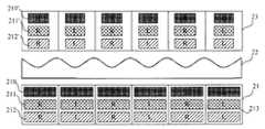
도 2는 본 발명의 입체 디스플레이 장치의 평면 구조도를 나타낸다.
도 3은 도 2에 도시된 바와 같은 입체 디스플레이 장치에 의해 표시되는 이미지의 개략도를 나타낸다.
도 4는 도 2에 도시된 바와 같은 입체 디스플레이 장치의 일 실시예의 구조도를 나타낸다.
도 5는 도 4에 도시된 바와 같은 입체 디스플레이 장치로부터 관찰되는 바와 같은 픽셀 디스플레이 이미지의 개략도를 나타낸다.1 is a plan view of a conventional stereoscopic display device.
2 is a plan view of a stereoscopic display device according to the present invention.
Fig. 3 shows a schematic view of an image displayed by the stereoscopic display device as shown in Fig.
Fig. 4 shows a structural diagram of an embodiment of a stereoscopic display device as shown in Fig.
Fig. 5 shows a schematic view of a pixel display image as observed from a stereoscopic display device as shown in Fig.
이하, 해결해야 할 기술적 문제, 기술적 해법 및 장점들을 더 명확하게 하기 위해 도면들을 참조하는 실시예들을 상세히 설명한다.In the following, embodiments for referring to the drawings are described in detail in order to further clarify the technical problems, technical solutions and advantages to be solved.
도 2에 도시된 바와 같이, 본 발명의 일 실시예는 디스플레이 패널(21) 및 렌즈 격자(도시되지 않음)를 포함하고, 디스플레이 패널(21)과 렌즈 격자 사이에 배치된 파형 렌즈(22)를 더 포함하고, 파형 렌즈(22)의 파 마루는 디스플레이 패널의 블랙 매트릭스 영역에 대응하고, 파형 렌즈(22)의 파 골은 디스플레이 패널의 픽셀 영역에 대응하는 입체 디스플레이 장치를 제공한다. 대안으로서, 파 마루가 디스플레이 패널의 블랙 매트릭스 영역에 대응하고, 파 골이 디스플레이 패널의 픽셀 영역에 대응하는 한, 파형 렌즈(22)는 사인파 형상 렌즈일 수 있고, 물론 파형 렌즈(22)는 코사인파 형상 렌즈일 수도 있다.2, an embodiment of the present invention includes a
대안으로서, 사인파 형상 렌즈의 일 표면은 평면 형상으로 형성되고, 다른 면의 단면 윤곽은 사인파 형상으로 형성된다. 코사인파 형상 렌즈의 일 표면은 평면 형상으로 형성되고, 다른 면의 단면 윤곽은 코사인파 형상으로 형성된다. 파형 렌즈는 오목 렌즈들 및 볼록 렌즈들의 연속 배열에 의해 형성된다. 파형 렌즈의 하나의 파형 사이클은 디스플레이 패널(21)의 하나의 픽셀 영역(210, 211 또는 212)에 대응한다. 오목 렌즈들은 디스플레이 패널의 픽셀 영역에 대응하도록 배치된다. 볼록 렌즈들은 디스플레이 패널의 픽셀 영역들 사이의 블랙 매트릭스(213)에 대응하도록 배치된다.Alternatively, one surface of the sinusoidal lens is formed in a planar shape, and the cross-sectional contour of the other surface is formed in a sinusoidal shape. One surface of the cosine wave lens is formed in a planar shape, and the cross-sectional contour of the other surface is formed in a cosine wave shape. The corrugated lens is formed by a continuous arrangement of concave lenses and convex lenses. One waveform cycle of the waveform lens corresponds to one
본 발명의 실시예에 따르면, 사인파 형상 렌즈 또는 코사인파 형상 렌즈는 디스플레이 패널과 렌즈 격자 사이에 배치되고, 특히 파형 렌즈는 오목 렌즈들과 볼록 렌즈들의 연속 배열에 의해 형성될 수 있고, 오목 렌즈들은 디스플레이 패널의 픽셀 영역들에 대응하도록 배치되며, 따라서 픽셀 영역으로부터의 광이 오목 렌즈 내로 들어간 후에, 디스플레이 패널의 픽셀 영역의 픽셀을 통과하는 광의 광 스폿의 확대율은 오목 렌즈에 의해 나타나는 이미지는 축소된다는 원리에 기초하여 감소하며, 따라서 시점 이미지(23)에서 관찰되는 바와 같은 서브픽셀들(210', 211', 212')은 (도 3에 도시된 바와 같은) 디스플레이 패널의 서브픽셀들(210, 211, 212)에 비해 축소되고, 따라서 좌측 이미지를 우측 관찰 영역으로 방출할 가능성이 크게 감소하고, 우측 이미지를 좌측 관찰 영역으로 방출할 가능성도 크게 감소하여, 좌측 시차 이미지와 우측 시차 이미지 간의 크로스토크가 감소하며, 옆에서 관찰될 때에도, 좌측 시차 이미지와 우측 시차 이미지 간의 크로스토크가 발생하지 않는다. 전술한 본 발명의 실시예에서는, 픽셀의 크기를 물리적으로 줄일 필요가 없고, 따라서 디스플레이 패널의 휘도를 낮추지 않고서, 이미지들 간의 크로스토크를 줄이고, 입체 이미지 표시 효과를 개선한다.According to an embodiment of the present invention, a sine wave lens or a cosine wave lens is disposed between the display panel and the lens grating, and in particular, the wave lens can be formed by a continuous arrangement of concave lenses and convex lenses, The enlargement ratio of the light spot of the light passing through the pixels of the pixel area of the display panel after the light from the pixel area enters into the concave lens is such that the image represented by the concave lens is reduced And thus the subpixels 210 ', 211', 212 'as viewed in the
더욱이, 도 4에 도시된 바와 같이, 전술한 디스플레이 장치는 사전결정된 거리만큼 디스플레이 패널로부터 떨어져 배치된 렌즈 격자(24)를 더 포함하며, 파형 렌즈(22)(사인파 형상 렌즈 또는 코사인파 형상 렌즈)는 디스플레이 패널(21)과 렌즈 격자(24) 사이에 배치된다. 대안으로서, 렌즈 격자(24)는 볼록 렌즈들로 구성된다.4, the above-described display device further includes a
특히, 도 5에 도시된 바와 같이, 디스플레이 패널(21)의 백라이트로부터 방출되는 광(25)은 디스플레이 패널(21)의 컬러 필터를 거쳐 파형 렌즈(22)(사인파 형상 렌즈 또는 코사인파 형상 렌즈) 안으로 들어간 후에 렌즈 격자(24) 안으로 들어가며, 방출된 광(25)은 관찰자의 눈들 내로 들어간다.5, the
본 발명의 원리가 아래에 상세히 설명된다.The principles of the invention are described in detail below.
도 3 내지 5에 도시된 바와 같이, 파형 렌즈(22)(사인파 형상 렌즈 또는 코사인파 형상 렌즈)는 오목 렌즈들과 볼록 렌즈들의 연속 배열에 의해 형성되므로, 픽셀 영역으로부터 방출되는 광이 오목 렌즈를 통과할 때, 광은 확산 상태에 있고, 좌안 및 우안 시점들의 이미지들은 오목 렌즈와 렌즈 격자(24) 사이의 영역에 각각 이미징되며, 오목 렌즈에 의해 나타나는 이미지는 축소된다는 원리에 따라, 좌안 및 우안 시점들의 이미지들은 축소 이미지들이며, 따라서 디스플레이 패널의 픽셀 영역의 픽셀을 통과하는 광의 광 스폿의 확대율은 감소되고, 따라서 시점 이미지(23)에서 관찰되는 바와 같은 서브픽셀들(210', 211', 212')은 (도 3 및 도 5에 도시된 바와 같은) 디스플레이 패널의 서브픽셀들(210, 211, 212)에 비해 축소되며, 볼록 렌즈는 블랙 매트릭스의 부분에 대응하므로, 볼록 렌즈로부터 광이 방출되지 않을 수 있고, 오목 렌즈로부터 방출되는 광은 렌즈 격자(23) 내로 다시 들어가서 렌즈 격자(24)에 의해 굴절되며, 렌즈 격자(24)는 볼록 렌즈들로 구성되므로, 렌즈 격자(24)에 의해 굴절되는 광은 수렴될 수 있고, 따라서 좌안 시점에 대응하는 이미지(26)는 관찰자의 좌안 내로 방출되고, 우안 시점에 대응하는 이미지(27)는 관찰자의 우안 내로 방출되며, 또한 좌측 이미지를 우측 관찰 영역으로 방출할 가능성이 크게 감소하고, 우측 이미지를 좌측 관찰 영역으로 방출할 가능성도 크게 감소하여, 전술한 본 발명의 실시예에서는 이미지 크로스토크가 발생하지 않을 수 있거나, 이미지 크로스토크 현상이 감소할 수 있다.As shown in Figs. 3 to 5, since the wave-form lens 22 (sinusoidal lens or cosine wave-shaped lens) is formed by a continuous arrangement of concave lenses and convex lenses, On passing, the light is in a diffuse state, and the images of the left and right eye views are respectively imaged in the region between the concave lens and the lens grating 24, and the image represented by the concave lens is reduced, The magnification of the light spot of light passing through the pixels of the pixel area of the display panel is reduced and thus the subpixels 210 ', 211', 212 (as seen in the viewpoint image 23) 'Are reduced relative to the
전술한 본 발명의 실시예들에서, 파형 렌즈(22)(사인파 형상 렌즈 또는 코사인파 형상 렌즈)는 1.0㎜ 내지 5.0㎜의 초점 거리를 갖는 렌즈들로부터 선택될 수 있고, 렌즈 격자(24)는 5㎜ 내지 100㎜의 초점 거리를 갖는 렌즈 격자들로부터 선택될 수 있다.In the embodiments of the present invention described above, the waveform lens 22 (sine wave lens or cosine wave lens) may be selected from lenses having a focal length of 1.0 mm to 5.0 mm, and the
더욱이, 전술한 본 발명의 실시예들에서, 파형 렌즈(22)(사인파 형상 렌즈 또는 코사인파 형상 렌즈)는 디스플레이 패널의 디스플레이 영역에 대응하도록 배치되고, 렌즈 격자(24)의 크기는 파형 렌즈(22)(사인파 형상 렌즈 또는 코사인파 형상 렌즈)의 크기와 동일하다.Furthermore, in the above-described embodiments of the present invention, the waveform lens 22 (sine wave lens or cosine wave lens) is arranged to correspond to the display area of the display panel, 22 (sine wave lens or cosine wave lens).
파형 렌즈(22)(사인파 형상 렌즈 또는 코사인파 형상 렌즈)는 디스플레이 패널(21)의 정면에 0.05㎜ 내지 5.0㎜ 거리를 두고 배치될 수 있고, 렌즈 격자(24)는 디스플레이 패널(21)의 정면에 5㎜ 내지 100㎜ 거리를 두고 배치될 수 있다.The corrugated lens 22 (sine wave lens or cosine wave lens) may be disposed at a distance of 0.05 mm to 5.0 mm on the front surface of the
전술한 본 발명의 실시예에서는, 파형 렌즈(22)(사인파 형상 렌즈 또는 코사인파 형상 렌즈)를 사용함으로써 디스플레이 패널의 휘도를 낮추지 않고서, 이미지들 간의 크로스토크를 줄이고, 입체 이미지 표시 효과를 개선한다.In the embodiment of the present invention described above, the waveform lens 22 (sine wave lens or cosine wave lens) is used to reduce the crosstalk between images without lowering the brightness of the display panel and improve the effect of displaying stereoscopic images .
위의 설명은 본 발명의 바람직한 구현일 뿐이며, 본 발명의 원리로부터 벗어나지 않고서, 이 분야의 기술자들에 의해 소정의 개량 및 변경이 이루어질 수 있다는 점에 유의해야 하며, 이러한 개량 및 변경도 본 발명의 보호 범위로서 간주되어야 한다.It should be noted that the foregoing description is only a preferred implementation of the present invention and that certain modifications and changes may be made by those skilled in the art without departing from the principles of the invention, It should be regarded as a scope of protection.
Claims (12)
Translated fromKorean디스플레이 패널 및 렌즈 격자를 포함하고, 상기 디스플레이 패널과 상기 렌즈 격자 사이에 배치된 파형 렌즈를 더 포함하며,
상기 파형 렌즈의 파 마루는 상기 디스플레이 패널의 블랙 매트릭스 영역에 대응하고, 상기 파형 렌즈의 파 골은 상기 디스플레이 패널의 픽셀 영역에 대응하고,
상기 파형 렌즈는 사인파 형상 렌즈 또는 코사인파 형상 렌즈이고,
상기 파형 렌즈의 일 표면은 평면 형상으로 형성되고, 다른 면의 단면 윤곽은 사인파 형상 또는 코사인파 형상으로 형성되며,
상기 평면 형상으로 형성된 상기 일 표면은 상기 디스플레이 패널에 근접한 일측에 배치되고, 상기 다른 표면은 상기 렌즈 격자에 근접한 일측에 배치되는 입체 디스플레이 장치.A stereoscopic display apparatus comprising:
Further comprising a waveform lens including a display panel and a lens grating disposed between the display panel and the lens grating,
The parallax of the corrugated lens corresponds to a black matrix area of the display panel, the corrugation of the corrugated lens corresponds to a pixel area of the display panel,
Wherein the wave-form lens is a sine wave lens or a cosine wave lens,
Wherein one surface of the corrugated lens is formed in a planar shape and a cross-sectional contour of the other surface is formed in a sine wave shape or a cosine wave shape,
Wherein the one surface formed in a planar shape is disposed on one side close to the display panel and the other surface is disposed on one side close to the lens grating.
상기 파형 렌즈는 오목 렌즈들 및 볼록 렌즈들의 연속 배열에 의해 형성되는 입체 디스플레이 장치.The method according to claim 1,
Wherein the wave-form lens is formed by a continuous arrangement of concave lenses and convex lenses.
상기 파형 렌즈의 하나의 파형 사이클은 상기 디스플레이 패널의 하나의 픽셀 영역에 대응하는 입체 디스플레이 장치.The method according to claim 1,
Wherein one waveform cycle of the waveform lens corresponds to one pixel area of the display panel.
상기 오목 렌즈들은 상기 디스플레이 패널의 상기 픽셀 영역에 대응하도록 배치되는 입체 디스플레이 장치.6. The method of claim 5,
Wherein the concave lenses are arranged to correspond to the pixel area of the display panel.
상기 볼록 렌즈들은 상기 디스플레이 패널의 상기 픽셀 영역들 사이의 상기 블랙 매트릭스에 대응하도록 배치되는 입체 디스플레이 장치.6. The method of claim 5,
And the convex lenses are arranged to correspond to the black matrix between the pixel areas of the display panel.
상기 렌즈 격자는 볼록 렌즈들로 구성되는 입체 디스플레이 장치.The method according to any one of claims 1 and 5 to 8,
Wherein the lens grating is formed of convex lenses.
상기 렌즈 격자는 5㎜ 내지 100㎜의 초점 거리를 갖는 렌즈 격자들로부터 선택되는 입체 디스플레이 장치.10. The method of claim 9,
Wherein the lens grating is selected from lens gratings having a focal length of 5 mm to 100 mm.
상기 파형 렌즈는 상기 디스플레이 패널의 디스플레이 영역에 대응하도록 배치되는 입체 디스플레이 장치.The method according to claim 1,
Wherein the waveform lens is arranged to correspond to a display area of the display panel.
상기 파형 렌즈는 1.0㎜ 내지 5.0㎜의 초점 거리를 갖는 렌즈들로부터 선택되는 입체 디스플레이 장치.The method according to claim 1,
Wherein the corrugated lens is selected from lenses having a focal length of 1.0 mm to 5.0 mm.
Applications Claiming Priority (3)
| Application Number | Priority Date | Filing Date | Title |
|---|---|---|---|
| CN201310287473.X | 2013-07-10 | ||
| CN201310287473.XACN103345068B (en) | 2013-07-10 | 2013-07-10 | A kind of 3 d display device |
| PCT/CN2013/084759WO2015003431A1 (en) | 2013-07-10 | 2013-09-30 | Stereoscopic display device |
Publications (2)
| Publication Number | Publication Date |
|---|---|
| KR20150016928A KR20150016928A (en) | 2015-02-13 |
| KR101570311B1true KR101570311B1 (en) | 2015-11-18 |
Family
ID=49279879
Family Applications (1)
| Application Number | Title | Priority Date | Filing Date |
|---|---|---|---|
| KR1020147012652AActiveKR101570311B1 (en) | 2013-07-10 | 2013-09-30 | Stereoscopic display device |
Country Status (6)
| Country | Link |
|---|---|
| US (1) | US9891441B2 (en) |
| EP (1) | EP3021156A4 (en) |
| JP (1) | JP6154957B2 (en) |
| KR (1) | KR101570311B1 (en) |
| CN (1) | CN103345068B (en) |
| WO (1) | WO2015003431A1 (en) |
Cited By (1)
| Publication number | Priority date | Publication date | Assignee | Title |
|---|---|---|---|---|
| KR20180109001A (en)* | 2017-03-24 | 2018-10-05 | 삼성디스플레이 주식회사 | Display device |
Families Citing this family (9)
| Publication number | Priority date | Publication date | Assignee | Title |
|---|---|---|---|---|
| CN105093541A (en)* | 2014-05-22 | 2015-11-25 | 华为技术有限公司 | Display device |
| CN104238127A (en) | 2014-09-12 | 2014-12-24 | 京东方科技集团股份有限公司 | Naked-eye three-dimensional display device |
| JP6546066B2 (en)* | 2015-10-27 | 2019-07-17 | Ntn株式会社 | Fixed type constant velocity universal joint and bearing device for wheel |
| CN106959551B (en)* | 2016-01-08 | 2023-12-19 | 京东方科技集团股份有限公司 | Display device and driving method thereof |
| CN105898286A (en)* | 2016-04-11 | 2016-08-24 | 北京邮电大学 | Three-dimensional image display device |
| CN109633946B (en)* | 2019-01-31 | 2022-05-24 | 上海天马微电子有限公司 | Display device, manufacturing method thereof and 3D printing system |
| CN110082923A (en)* | 2019-06-11 | 2019-08-02 | 深圳奇屏科技有限公司 | A kind of 3D display device module |
| CN111725418B (en)* | 2020-05-21 | 2022-08-30 | 合肥维信诺科技有限公司 | Display panel |
| CN113406809A (en)* | 2021-07-02 | 2021-09-17 | 广东未来科技有限公司 | Stereoscopic display device |
Citations (1)
| Publication number | Priority date | Publication date | Assignee | Title |
|---|---|---|---|---|
| CN101620319A (en) | 2009-08-06 | 2010-01-06 | 深圳超多维光电子有限公司 | Moire-free three-dimensional display device |
Family Cites Families (22)
| Publication number | Priority date | Publication date | Assignee | Title |
|---|---|---|---|---|
| US2086556A (en)* | 1934-01-11 | 1937-07-13 | Jacobson Beatrice | Projection screen for obtaining stereoscopic effects |
| JPS592014B2 (en)* | 1981-06-22 | 1984-01-17 | 清三郎 木村 | Stereoscopic lens |
| JPS592014A (en) | 1982-06-28 | 1984-01-07 | Nippon Denso Co Ltd | Video device for automobile |
| JP2955327B2 (en)* | 1990-05-25 | 1999-10-04 | 日本放送協会 | 3D image display |
| JPH09101483A (en)* | 1995-10-03 | 1997-04-15 | Hiroshi Inoue | Stereoscopic display mirror |
| US6151089A (en)* | 1998-01-20 | 2000-11-21 | Sony Corporation | Reflection type display with light waveguide with inclined and planar surface sections |
| JP3418729B2 (en) | 2000-08-25 | 2003-06-23 | ティーディーケイ株式会社 | Screen display device |
| JP4653417B2 (en) | 2004-05-13 | 2011-03-16 | 株式会社リコー | Spatial light modulator and image display device |
| JP4871540B2 (en) | 2005-07-25 | 2012-02-08 | キヤノン株式会社 | 3D image display device |
| CN2921860Y (en) | 2006-03-08 | 2007-07-11 | 汤维盛 | Compound lens plate |
| ATE530022T1 (en)* | 2006-08-17 | 2011-11-15 | Koninkl Philips Electronics Nv | DISPLAY DEVICE |
| GB0704803D0 (en)* | 2007-03-13 | 2007-04-18 | Cambridge Flat Projection | Structured colour illumination of lcd's |
| WO2008114813A1 (en) | 2007-03-22 | 2008-09-25 | Michiyoshi Nagashima | Image display device and panel manufacturing method |
| JP5571662B2 (en) | 2008-06-27 | 2014-08-13 | コーニンクレッカ フィリップス エヌ ヴェ | Autostereoscopic display device |
| JP2010266829A (en)* | 2009-05-18 | 2010-11-25 | Three M Innovative Properties Co | Optical member and device using the same |
| KR20120018370A (en)* | 2009-05-28 | 2012-03-02 | 코닌클리케 필립스 일렉트로닉스 엔.브이. | Autostereoscopic display device |
| CN101702057B (en)* | 2009-11-06 | 2011-02-16 | 四川大学 | Free three-dimensional display with condensing cylindrical grating |
| KR101160555B1 (en) | 2010-04-28 | 2012-06-27 | 황장환 | Three-Dimensional Film and 3D Display Using the Same |
| JP2011128636A (en) | 2011-01-20 | 2011-06-30 | Dainippon Printing Co Ltd | Color stereoscopic display device |
| CN102523470A (en) | 2012-01-08 | 2012-06-27 | 四川大学 | Method for reducing image crosstalk of stereoscopic liquid crystal display of cylindrical lens grating by adopting polarized light element |
| CN202486466U (en)* | 2012-02-29 | 2012-10-10 | 南京中电熊猫液晶显示科技有限公司 | Polarized three-dimensional (3D) liquid crystal display for improving viewing angle |
| CN102662208B (en)* | 2012-03-15 | 2015-05-20 | 京东方科技集团股份有限公司 | Lenticular lens grating, liquid crystal grating and display device |
- 2013
- 2013-07-10CNCN201310287473.XApatent/CN103345068B/enactiveActive
- 2013-09-30USUS14/353,519patent/US9891441B2/enactiveActive
- 2013-09-30EPEP13846243.7Apatent/EP3021156A4/ennot_activeCeased
- 2013-09-30WOPCT/CN2013/084759patent/WO2015003431A1/enactiveApplication Filing
- 2013-09-30JPJP2016524654Apatent/JP6154957B2/enactiveActive
- 2013-09-30KRKR1020147012652Apatent/KR101570311B1/enactiveActive
Patent Citations (1)
| Publication number | Priority date | Publication date | Assignee | Title |
|---|---|---|---|---|
| CN101620319A (en) | 2009-08-06 | 2010-01-06 | 深圳超多维光电子有限公司 | Moire-free three-dimensional display device |
Cited By (2)
| Publication number | Priority date | Publication date | Assignee | Title |
|---|---|---|---|---|
| KR20180109001A (en)* | 2017-03-24 | 2018-10-05 | 삼성디스플레이 주식회사 | Display device |
| KR102449093B1 (en)* | 2017-03-24 | 2022-09-29 | 삼성디스플레이 주식회사 | display device |
Also Published As
| Publication number | Publication date |
|---|---|
| CN103345068A (en) | 2013-10-09 |
| WO2015003431A1 (en) | 2015-01-15 |
| EP3021156A4 (en) | 2017-03-01 |
| EP3021156A1 (en) | 2016-05-18 |
| CN103345068B (en) | 2016-01-20 |
| KR20150016928A (en) | 2015-02-13 |
| US20150124316A1 (en) | 2015-05-07 |
| JP2016529540A (en) | 2016-09-23 |
| US9891441B2 (en) | 2018-02-13 |
| JP6154957B2 (en) | 2017-06-28 |
Similar Documents
| Publication | Publication Date | Title |
|---|---|---|
| KR101570311B1 (en) | Stereoscopic display device | |
| JP4371012B2 (en) | Image display device, portable terminal device, display panel, and lens | |
| US9274345B2 (en) | Multiple view display | |
| CN104965308B (en) | Three-dimensional display apparatus and its display methods | |
| EP2818914A1 (en) | Liquid crystal lens and process for manufacturing the same, stereoscopic display device and process for manufacturing the same | |
| US20120162194A1 (en) | Stereo display apparatus and lens array thereof | |
| US9762894B2 (en) | 3D display method | |
| CA2971947A1 (en) | Autostereoscopic display device | |
| JP2010026499A (en) | Stereoscopic image display device | |
| CN103091854B (en) | Stereo display device | |
| CA2971908C (en) | Autostereoscopic display device | |
| JP2004264762A (en) | Stereoscopic image display device | |
| KR20140041102A (en) | Display panel and display apparatus having the same | |
| KR102595087B1 (en) | Lens panel and display device including the same | |
| JP5024800B2 (en) | Image display device | |
| JP2004280079A (en) | Picture display device and portable terminal device using the same | |
| TWI486635B (en) | Stereoscopic display device | |
| CN103728729B (en) | A kind of naked eye three-dimensional display | |
| KR102704962B1 (en) | Lens panel and display device including the same | |
| KR20100137725A (en) | Switching stereoscopic filter and switching stereoscopic image display device using the same | |
| KR102645722B1 (en) | Lens panel and display device comprising the same | |
| US10976587B2 (en) | Display apparatus and display method | |
| US20150234196A1 (en) | Image display apparatus, lenticular lens, and image display method | |
| JP2013068682A (en) | Stereoscopic display device | |
| US9215451B2 (en) | Liquid crystal display and method for generating 3D images by matching a software optical grating |
Legal Events
| Date | Code | Title | Description |
|---|---|---|---|
| A201 | Request for examination | ||
| PA0105 | International application | St.27 status event code:A-0-1-A10-A15-nap-PA0105 | |
| PA0201 | Request for examination | St.27 status event code:A-1-2-D10-D11-exm-PA0201 | |
| D13-X000 | Search requested | St.27 status event code:A-1-2-D10-D13-srh-X000 | |
| PG1501 | Laying open of application | St.27 status event code:A-1-1-Q10-Q12-nap-PG1501 | |
| D14-X000 | Search report completed | St.27 status event code:A-1-2-D10-D14-srh-X000 | |
| E902 | Notification of reason for refusal | ||
| PE0902 | Notice of grounds for rejection | St.27 status event code:A-1-2-D10-D21-exm-PE0902 | |
| E13-X000 | Pre-grant limitation requested | St.27 status event code:A-2-3-E10-E13-lim-X000 | |
| P11-X000 | Amendment of application requested | St.27 status event code:A-2-2-P10-P11-nap-X000 | |
| P13-X000 | Application amended | St.27 status event code:A-2-2-P10-P13-nap-X000 | |
| E701 | Decision to grant or registration of patent right | ||
| PE0701 | Decision of registration | St.27 status event code:A-1-2-D10-D22-exm-PE0701 | |
| GRNT | Written decision to grant | ||
| PR0701 | Registration of establishment | St.27 status event code:A-2-4-F10-F11-exm-PR0701 | |
| PR1002 | Payment of registration fee | St.27 status event code:A-2-2-U10-U12-oth-PR1002 Fee payment year number:1 | |
| PG1601 | Publication of registration | St.27 status event code:A-4-4-Q10-Q13-nap-PG1601 | |
| FPAY | Annual fee payment | Payment date:20181101 Year of fee payment:4 | |
| PR1001 | Payment of annual fee | St.27 status event code:A-4-4-U10-U11-oth-PR1001 Fee payment year number:4 | |
| PR1001 | Payment of annual fee | St.27 status event code:A-4-4-U10-U11-oth-PR1001 Fee payment year number:5 | |
| P22-X000 | Classification modified | St.27 status event code:A-4-4-P10-P22-nap-X000 | |
| P22-X000 | Classification modified | St.27 status event code:A-4-4-P10-P22-nap-X000 | |
| PR1001 | Payment of annual fee | St.27 status event code:A-4-4-U10-U11-oth-PR1001 Fee payment year number:6 | |
| PR1001 | Payment of annual fee | St.27 status event code:A-4-4-U10-U11-oth-PR1001 Fee payment year number:7 | |
| PR1001 | Payment of annual fee | St.27 status event code:A-4-4-U10-U11-oth-PR1001 Fee payment year number:8 | |
| PR1001 | Payment of annual fee | St.27 status event code:A-4-4-U10-U11-oth-PR1001 Fee payment year number:9 | |
| PR1001 | Payment of annual fee | St.27 status event code:A-4-4-U10-U11-oth-PR1001 Fee payment year number:10 | |
| PR1001 | Payment of annual fee | St.27 status event code:A-4-4-U10-U11-oth-PR1001 Fee payment year number:11 |