KR101569836B1 - Microfluidic device initialization method microfluidic device initialization apparatus and microfluidic device package - Google Patents
Microfluidic device initialization method microfluidic device initialization apparatus and microfluidic device packageDownload PDFInfo
- Publication number
- KR101569836B1 KR101569836B1KR1020090102821AKR20090102821AKR101569836B1KR 101569836 B1KR101569836 B1KR 101569836B1KR 1020090102821 AKR1020090102821 AKR 1020090102821AKR 20090102821 AKR20090102821 AKR 20090102821AKR 101569836 B1KR101569836 B1KR 101569836B1
- Authority
- KR
- South Korea
- Prior art keywords
- substrate
- microfluidic device
- pneumatic
- holes
- polymer film
- Prior art date
- Legal status (The legal status is an assumption and is not a legal conclusion. Google has not performed a legal analysis and makes no representation as to the accuracy of the status listed.)
- Active
Links
Images


Classifications
- F—MECHANICAL ENGINEERING; LIGHTING; HEATING; WEAPONS; BLASTING
- F16—ENGINEERING ELEMENTS AND UNITS; GENERAL MEASURES FOR PRODUCING AND MAINTAINING EFFECTIVE FUNCTIONING OF MACHINES OR INSTALLATIONS; THERMAL INSULATION IN GENERAL
- F16K—VALVES; TAPS; COCKS; ACTUATING-FLOATS; DEVICES FOR VENTING OR AERATING
- F16K99/00—Subject matter not provided for in other groups of this subclass
- F16K99/0001—Microvalves
- F16K99/0034—Operating means specially adapted for microvalves
- F16K99/0055—Operating means specially adapted for microvalves actuated by fluids
- F16K99/0059—Operating means specially adapted for microvalves actuated by fluids actuated by a pilot fluid
- B—PERFORMING OPERATIONS; TRANSPORTING
- B01—PHYSICAL OR CHEMICAL PROCESSES OR APPARATUS IN GENERAL
- B01L—CHEMICAL OR PHYSICAL LABORATORY APPARATUS FOR GENERAL USE
- B01L3/00—Containers or dishes for laboratory use, e.g. laboratory glassware; Droppers
- B01L3/50—Containers for the purpose of retaining a material to be analysed, e.g. test tubes
- B01L3/502—Containers for the purpose of retaining a material to be analysed, e.g. test tubes with fluid transport, e.g. in multi-compartment structures
- B01L3/5027—Containers for the purpose of retaining a material to be analysed, e.g. test tubes with fluid transport, e.g. in multi-compartment structures by integrated microfluidic structures, i.e. dimensions of channels and chambers are such that surface tension forces are important, e.g. lab-on-a-chip
- B01L3/502738—Containers for the purpose of retaining a material to be analysed, e.g. test tubes with fluid transport, e.g. in multi-compartment structures by integrated microfluidic structures, i.e. dimensions of channels and chambers are such that surface tension forces are important, e.g. lab-on-a-chip characterised by integrated valves
- F—MECHANICAL ENGINEERING; LIGHTING; HEATING; WEAPONS; BLASTING
- F16—ENGINEERING ELEMENTS AND UNITS; GENERAL MEASURES FOR PRODUCING AND MAINTAINING EFFECTIVE FUNCTIONING OF MACHINES OR INSTALLATIONS; THERMAL INSULATION IN GENERAL
- F16K—VALVES; TAPS; COCKS; ACTUATING-FLOATS; DEVICES FOR VENTING OR AERATING
- F16K99/00—Subject matter not provided for in other groups of this subclass
- F16K99/0001—Microvalves
- F16K99/0003—Constructional types of microvalves; Details of the cutting-off member
- F16K99/0015—Diaphragm or membrane valves
- B—PERFORMING OPERATIONS; TRANSPORTING
- B01—PHYSICAL OR CHEMICAL PROCESSES OR APPARATUS IN GENERAL
- B01L—CHEMICAL OR PHYSICAL LABORATORY APPARATUS FOR GENERAL USE
- B01L2200/00—Solutions for specific problems relating to chemical or physical laboratory apparatus
- B01L2200/14—Process control and prevention of errors
- B01L2200/143—Quality control, feedback systems
- B—PERFORMING OPERATIONS; TRANSPORTING
- B01—PHYSICAL OR CHEMICAL PROCESSES OR APPARATUS IN GENERAL
- B01L—CHEMICAL OR PHYSICAL LABORATORY APPARATUS FOR GENERAL USE
- B01L2300/00—Additional constructional details
- B01L2300/08—Geometry, shape and general structure
- B01L2300/0809—Geometry, shape and general structure rectangular shaped
- B01L2300/0816—Cards, e.g. flat sample carriers usually with flow in two horizontal directions
- B—PERFORMING OPERATIONS; TRANSPORTING
- B01—PHYSICAL OR CHEMICAL PROCESSES OR APPARATUS IN GENERAL
- B01L—CHEMICAL OR PHYSICAL LABORATORY APPARATUS FOR GENERAL USE
- B01L2300/00—Additional constructional details
- B01L2300/08—Geometry, shape and general structure
- B01L2300/0887—Laminated structure
- B—PERFORMING OPERATIONS; TRANSPORTING
- B01—PHYSICAL OR CHEMICAL PROCESSES OR APPARATUS IN GENERAL
- B01L—CHEMICAL OR PHYSICAL LABORATORY APPARATUS FOR GENERAL USE
- B01L2400/00—Moving or stopping fluids
- B01L2400/06—Valves, specific forms thereof
- B01L2400/0633—Valves, specific forms thereof with moving parts
- B01L2400/0638—Valves, specific forms thereof with moving parts membrane valves, flap valves
- B—PERFORMING OPERATIONS; TRANSPORTING
- B01—PHYSICAL OR CHEMICAL PROCESSES OR APPARATUS IN GENERAL
- B01L—CHEMICAL OR PHYSICAL LABORATORY APPARATUS FOR GENERAL USE
- B01L2400/00—Moving or stopping fluids
- B01L2400/06—Valves, specific forms thereof
- B01L2400/0633—Valves, specific forms thereof with moving parts
- B01L2400/0655—Valves, specific forms thereof with moving parts pinch valves
- F—MECHANICAL ENGINEERING; LIGHTING; HEATING; WEAPONS; BLASTING
- F16—ENGINEERING ELEMENTS AND UNITS; GENERAL MEASURES FOR PRODUCING AND MAINTAINING EFFECTIVE FUNCTIONING OF MACHINES OR INSTALLATIONS; THERMAL INSULATION IN GENERAL
- F16K—VALVES; TAPS; COCKS; ACTUATING-FLOATS; DEVICES FOR VENTING OR AERATING
- F16K99/00—Subject matter not provided for in other groups of this subclass
- F16K2099/0073—Fabrication methods specifically adapted for microvalves
- F16K2099/008—Multi-layer fabrications
- F—MECHANICAL ENGINEERING; LIGHTING; HEATING; WEAPONS; BLASTING
- F16—ENGINEERING ELEMENTS AND UNITS; GENERAL MEASURES FOR PRODUCING AND MAINTAINING EFFECTIVE FUNCTIONING OF MACHINES OR INSTALLATIONS; THERMAL INSULATION IN GENERAL
- F16K—VALVES; TAPS; COCKS; ACTUATING-FLOATS; DEVICES FOR VENTING OR AERATING
- F16K99/00—Subject matter not provided for in other groups of this subclass
- F16K2099/0082—Microvalves adapted for a particular use
- F16K2099/0084—Chemistry or biology, e.g. "lab-on-a-chip" technology
- G—PHYSICS
- G01—MEASURING; TESTING
- G01N—INVESTIGATING OR ANALYSING MATERIALS BY DETERMINING THEIR CHEMICAL OR PHYSICAL PROPERTIES
- G01N27/00—Investigating or analysing materials by the use of electric, electrochemical, or magnetic means
- G01N27/26—Investigating or analysing materials by the use of electric, electrochemical, or magnetic means by investigating electrochemical variables; by using electrolysis or electrophoresis
- G01N27/416—Systems
- G01N27/447—Systems using electrophoresis
- G01N27/44756—Apparatus specially adapted therefor
- G01N27/44791—Microapparatus
- Y—GENERAL TAGGING OF NEW TECHNOLOGICAL DEVELOPMENTS; GENERAL TAGGING OF CROSS-SECTIONAL TECHNOLOGIES SPANNING OVER SEVERAL SECTIONS OF THE IPC; TECHNICAL SUBJECTS COVERED BY FORMER USPC CROSS-REFERENCE ART COLLECTIONS [XRACs] AND DIGESTS
- Y10—TECHNICAL SUBJECTS COVERED BY FORMER USPC
- Y10T—TECHNICAL SUBJECTS COVERED BY FORMER US CLASSIFICATION
- Y10T137/00—Fluid handling
- Y10T137/0318—Processes
- Y—GENERAL TAGGING OF NEW TECHNOLOGICAL DEVELOPMENTS; GENERAL TAGGING OF CROSS-SECTIONAL TECHNOLOGIES SPANNING OVER SEVERAL SECTIONS OF THE IPC; TECHNICAL SUBJECTS COVERED BY FORMER USPC CROSS-REFERENCE ART COLLECTIONS [XRACs] AND DIGESTS
- Y10—TECHNICAL SUBJECTS COVERED BY FORMER USPC
- Y10T—TECHNICAL SUBJECTS COVERED BY FORMER US CLASSIFICATION
- Y10T137/00—Fluid handling
- Y10T137/206—Flow affected by fluid contact, energy field or coanda effect [e.g., pure fluid device or system]
- Y10T137/218—Means to regulate or vary operation of device
- Y10T137/2202—By movable element
- Y—GENERAL TAGGING OF NEW TECHNOLOGICAL DEVELOPMENTS; GENERAL TAGGING OF CROSS-SECTIONAL TECHNOLOGIES SPANNING OVER SEVERAL SECTIONS OF THE IPC; TECHNICAL SUBJECTS COVERED BY FORMER USPC CROSS-REFERENCE ART COLLECTIONS [XRACs] AND DIGESTS
- Y10—TECHNICAL SUBJECTS COVERED BY FORMER USPC
- Y10T—TECHNICAL SUBJECTS COVERED BY FORMER US CLASSIFICATION
- Y10T137/00—Fluid handling
- Y10T137/206—Flow affected by fluid contact, energy field or coanda effect [e.g., pure fluid device or system]
- Y10T137/2224—Structure of body of device
- Y—GENERAL TAGGING OF NEW TECHNOLOGICAL DEVELOPMENTS; GENERAL TAGGING OF CROSS-SECTIONAL TECHNOLOGIES SPANNING OVER SEVERAL SECTIONS OF THE IPC; TECHNICAL SUBJECTS COVERED BY FORMER USPC CROSS-REFERENCE ART COLLECTIONS [XRACs] AND DIGESTS
- Y10—TECHNICAL SUBJECTS COVERED BY FORMER USPC
- Y10T—TECHNICAL SUBJECTS COVERED BY FORMER US CLASSIFICATION
- Y10T436/00—Chemistry: analytical and immunological testing
- Y10T436/25—Chemistry: analytical and immunological testing including sample preparation
- Y10T436/2575—Volumetric liquid transfer
Landscapes
- Chemical & Material Sciences (AREA)
- Engineering & Computer Science (AREA)
- General Engineering & Computer Science (AREA)
- Dispersion Chemistry (AREA)
- Mechanical Engineering (AREA)
- Health & Medical Sciences (AREA)
- Analytical Chemistry (AREA)
- General Health & Medical Sciences (AREA)
- Hematology (AREA)
- Clinical Laboratory Science (AREA)
- Chemical Kinetics & Catalysis (AREA)
- Automatic Analysis And Handling Materials Therefor (AREA)
Abstract
Translated fromKoreanDescription
Translated fromKorean미세 유체 소자의 초기화 방법, 미세 유체 소자의 초기화 장치, 및 미세 유체 소자 패키지를 개시한다. 더욱 상세하게는, 폴리머 필름을 이용한 밸브를 갖는 미세 유체 소자에서 밸브의 온/오프를 초기화시키는 방법 및 장치와 밸브의 온/오프 초기화가 용이한 미세 유체 소자 패키지를 개시한다. A method of initializing a microfluidic device, an initialization device of a microfluidic device, and a microfluidic device package. More particularly, the present invention discloses a method and apparatus for initializing a valve on / off in a microfluidic device having a valve using a polymer film, and a microfluidic device package that facilitates on / off initialization of the valve.
임상 혹은 환경과 관련된 시료의 분석은 일련의 생화학적, 화학적, 기계적 처리과정을 통하여 이루어진다. 최근에는 생물학적인 시료의 진단이나 모니터링을 위한 기술개발이 상당한 관심을 끌고 있다. 최근 핵산을 기반으로 한 분자진단 방법은 그 정확도 및 민감도가 우수하여 감염성 질환이나 암진단, 약물유전체학, 신약 개발 등에서 활용도가 상당히 증가하고 있다.Analysis of clinical or environmental samples is done through a series of biochemical, chemical and mechanical processes. In recent years, the development of techniques for the diagnosis and monitoring of biological samples has attracted considerable attention. Recently, nucleic acid based molecular diagnostic methods have been used in infectious diseases, cancer diagnosis, pharmacogenomics, and new drug development because their accuracy and sensitivity are excellent.
이러한 다양한 목적에 따라 시료를 간편하고 정밀하게 분석하기 위하여 미세 유체 소자가 널리 사용되고 있다. 미세 유체 소자는 얇은 기판 상에 시료 유입구, 시료 유출구, 미세 유로, 반응 챔버 등이 다수 형성되어 있어서, 하나의 시료에 대 해 다양한 검사를 간편하게 수행할 수 있다. 또한, 미세 유체 소자에서 시료 및 시약이 원하는 위치로 정확하게 제공될 수 있도록 미세 유로 내에는 미세한 밸브가 제공될 수 있다. 이러한 밸브는 통상적으로 얇은 폴리머 필름을 사용하여 형성된다. 미세 유체 소자의 사용시에, 폴리머 필름으로 이루어진 미세한 밸브가 정확하게 온/오프 될 수 있도록 제어하는 것이 중요하다.Microfluidic devices are widely used for simple and precise analysis of samples according to these various purposes. The microfluidic device has many sample inlet, sample outlet, microfluidic channel, and reaction chamber on a thin substrate, so that various tests can be easily performed on one sample. Further, in the microfluidic device, a minute valve can be provided in the microchannel so that the sample and the reagent can be accurately provided to a desired position. Such valves are typically formed using thin polymer films. When using a microfluidic device, it is important to control so that a minute valve made of a polymer film can be accurately turned on and off.
폴리머 필름을 이용한 밸브를 갖는 미세 유체 소자에서 밸브의 온/오프를 초기화시키는 방법 및 장치를 제공한다.A method and an apparatus for initializing on / off of a valve in a microfluidic device having a valve using a polymer film are provided.
또한, 폴리머 필름으로 이루어진 밸브의 온/오프 초기화가 용이한 미세 유체 소자 패키지를 제공한다.Also provided is a microfluidic device package in which the on / off initialization of a valve made of a polymer film is easy.
한 유형에 따른 개시된 미세 유체 소자의 초기화 방법은, 예를 들어, 미세 유로 내에 돌출하여 형성된 밸브 시트를 갖는 제 1 기판, 상기 밸브 시트와 대응하는 위치에 빈 공간이 마련되어 있는 제 2 기판, 및 상기 제 1 기판과 제 2 기판 사이에 배치된 폴리머 필름을 갖는 미세 유체 소자에 대하여 상기 제 1 기판의 미세 유로에 공압을 인가하는 동시에 상기 제 2 기판의 공간에 진공을 인가함으로써 상기 폴리머 필름이 상기 밸브 시트의 표면으로부터 떨어지도록 하는 단계를 포함할 수 있다.A method of initializing a disclosed microfluidic device according to one type includes, for example, a first substrate having a valve sheet protruded in a microchannel, a second substrate having a void space at a position corresponding to the valve sheet, Applying a vacuum to the microfluidic channel of the first substrate and applying a vacuum to the space of the second substrate with respect to the microfluidic device having the polymer film disposed between the first substrate and the second substrate, So as to be separated from the surface of the sheet.
또한 상기 미세 유체 소자의 초기화 방법은, 상기 폴리머 필름이 상기 밸브 시트의 표면으로부터 떨어지도록 하는 단계 후에, 상기 제 2 기판의 공간에 공압을 인가함으로써 상기 폴리머 필름을 상기 밸브 시트를 향해 미는 단계를 더 포함할 수 있다.The step of initializing the microfluidic device may further comprise the step of pushing the polymer film toward the valve seat by applying a pneumatic pressure to the space of the second substrate after the step of causing the polymer film to move away from the surface of the valve seat .
상기 미세 유체 소자의 초기화 방법은 또한, 상기 폴리머 필름이 상기 밸브 시트의 표면으로부터 떨어지도록 하는 단계와 상기 폴리머 필름을 상기 밸브 시트 를 향해 미는 단계를 반복적으로 수행할 수도 있다.The method of initializing the microfluidic device may also repeatedly perform the steps of causing the polymer film to fall off the surface of the valve seat and pushing the polymer film toward the valve seat.
상기 폴리머 필름이 상기 밸브 시트의 표면으로부터 떨어지도록 하는 단계에서, 상기 폴리머 필름이 밸브 시트의 표면으로부터 떨어질 때까지 공압 또는 진공을 증가시킬 수 있다.In the step of causing the polymer film to fall off the surface of the valve seat, the pneumatic or vacuum can be increased until the polymer film falls off the surface of the valve seat.
예를 들어, 상기 폴리머 필름이 상기 밸브 시트의 표면으로부터 떨어지도록 하는 단계는 미세 유체 소자의 제작 직후에 또는 미세 유체 소자의 사용 직전에 수행될 수 있다.For example, the step of allowing the polymer film to fall off the surface of the valve seat may be performed immediately after fabrication of the microfluidic device or just prior to use of the microfluidic device.
한편, 한 유형에 따른 미세 유체 소자 초기화 장치는, 미세 유체 소자를 사이에 두고 서로 결합하는 하부 기판과 상부 기판; 상기 하부 기판과 상부 기판의 서로 대응하는 표면들에 각각 형성된 미세 유체 소자 안착부; 상기 하부 기판과 상부 기판의 안착부 표면에 각각 형성된 다수의 공압홀; 및 진공 펌프 또는 공압 펌프와 연결되어 상기 공압홀들을 통해 미세 유체 소자에 진공 또는 공압을 인가할 수 있도록, 상기 하부 기판 및 상부 기판의 외부 표면에 각각 배치된 다수의 공압 포트를 포함할 수 있다.Meanwhile, a microfluidic device initialization device according to one type includes: a lower substrate and an upper substrate coupled to each other with a microfluidic device interposed therebetween; A microfluidic device seating part formed on the surfaces of the lower substrate and the upper substrate, A plurality of pneumatic holes respectively formed on the surfaces of the seating portions of the lower substrate and the upper substrate; And a plurality of pneumatic ports respectively connected to the vacuum pump or the pneumatic pump and disposed on the outer surfaces of the lower substrate and the upper substrate so as to apply vacuum or air pressure to the microfluidic devices through the pneumatic holes.
상기 미세 유체 소자 초기화 장치는, 상기 하부 기판의 표면에 형성된 결합홈 및 상기 결합홈에 끼워지도록 상기 상부 기판의 표면에 형성된 결합폴을 더 포함할 수 있다.The microfluidic device initialization device may further include a coupling groove formed on a surface of the lower substrate and a coupling pole formed on a surface of the upper substrate to be inserted into the coupling groove.
여기서, 상기 하부 기판의 안착부에 형성된 공압홀들의 위치는 미세 유체 소자의 대향하는 제 1 기판 상에 형성된 홀들의 위치와 대응하도록 배열될 수 있다.Here, the positions of the pneumatic holes formed in the seating portion of the lower substrate may be arranged to correspond to the positions of the holes formed on the opposing first substrate of the microfluidic device.
또한, 상기 상부 기판의 안착부에 형성된 공압홀들의 위치는 미세 유체 소자 의 대향하는 제 2 기판 상에 형성된 홀들의 위치와 대응하도록 배열될 수 있다.In addition, the positions of the pneumatic holes formed in the seating portion of the upper substrate may be arranged to correspond to the positions of the holes formed on the opposing second substrate of the microfluidic device.
특히, 상기 공압홀들은 미세 유체 소자 내의 밸브의 개폐와 관련된 홀들에만 대응하도록 형성될 수도 있다.In particular, the pneumatic holes may be formed so as to correspond only to the holes associated with the opening and closing of the valve in the microfluidic device.
예를 들어, 상기 공압 포트는 하부 기판에 배치된 제 1 공압 포트 및 상부 기판에 배치된 제 2 및 제 3 공압 포트를 포함할 수 있다.For example, the pneumatic port may include a first pneumatic port disposed on the lower substrate and a second and third pneumatic port disposed on the upper substrate.
이 경우에, 상기 제 1 및 제 2 공압 포트는 공압 펌프와 연결될 수 있으며, 상기 제 3 공압 포트는 진공 펌프와 연결될 수 있다.In this case, the first and second pneumatic ports may be connected to a pneumatic pump, and the third pneumatic port may be connected to a vacuum pump.
또한, 상기 제 1 내지 제 3 공압 포트는 진공 또는 공압의 인가를 위한 공압 포트의 역할과 시료의 유입을 위한 시료 유입 포트의 역할을 공유할 수 있다.In addition, the first to third pneumatic ports may share a role of a pneumatic port for applying a vacuum or a pneumatic pressure, and a sample inlet port for introducing a sample.
또한, 상기 하부 기판에는 제 1 공압 포트 이외에 시료의 유입을 위한 적어도 하나의 포트가 더 설치될 수 있다.In addition, the lower substrate may be provided with at least one port for introducing the sample in addition to the first pneumatic port.
또한, 상기 상부 기판에는 제 2 및 제 3 공압 포트 이외에 시료의 유입을 위한 적어도 하나의 포트가 더 설치될 수 있다.In addition, the upper substrate may be provided with at least one port for introducing the sample in addition to the second and third pneumatic ports.
개시된 한 유형에 따른 시료 분석 시스템은 상술한 구조의 미세 유체 소자 초기화 장치를 포함할 수 있다.A sample analyzing system according to one disclosed type may include a microfluidic device initialization device of the above-described structure.
개시된 한 유형에 따른 미세 유체 소자 패키지는, 상술한 구조의 미세 유체 소자 초기화 장치의 하부 기판과 상부 기판 및 그 사이의 미세 유체 소자가 하나의 제품으로서 함께 일체로 결합되어 제공될 수 있다.The microfluidic device package according to one of the disclosed types can be provided by integrally joining together the lower substrate and the upper substrate of the microfluidic device initializing device having the structure described above and the microfluidic devices therebetween as a single product.
또한, 다른 유형에 따른 미세 유체 소자 초기화 장치는, 기판; 상기 기판의 하부에 마련된 다수의 니들; 및 진공 펌프 또는 공압 펌프와 연결되어 상기 니들을 통해 미세 유체 소자에 진공 또는 공압을 인가할 수 있도록, 기판의 외부 표면에 배치된 적어도 하나의 공압 포트를 포함할 수 있다.In addition, another type of microfluidic device initialization device includes a substrate; A plurality of needles provided below the substrate; And at least one pneumatic port disposed on an outer surface of the substrate such that vacuum or pneumatic pressure can be applied to the microfluidic device through the needle in conjunction with a vacuum or pneumatic pump.
여기서, 상기 다수의 니들은 미세 유체 소자에 형성된 다수의 홀들의 위치와 대응하도록 어레이를 이룰 수 있다.Here, the plurality of needles may form an array to correspond to the positions of the plurality of holes formed in the microfluidic device.
특히, 상기 니들의 어레이는 미세 유체 소자의 밸브의 개폐와 관련된 홀들에만 대응하도록 형성될 수 있다.In particular, the array of needles may be formed to correspond only to the holes associated with the opening and closing of the valve of the microfluidic device.
예를 들어, 상기 미세 유체 소자 초기화 장치는 미세 유체 소자의 제 1 기판 상에 형성된 홀들과 대응하는 니들들의 어레이를 갖는 장치와 미세 유체 소자의 제 2 기판 상에 형성된 홀들과 대응하는 니들들의 어레이를 갖는 장치가 함께 쌍을 이루어 제공될 수 있다.For example, the microfluidic device initialization device may include an array of needles formed on a first substrate of a microfluidic device and an array of corresponding needles formed on a second substrate of the microfluidic device, May be provided together in pairs.
개시된 미세 유체 소자의 초기화 방법, 미세 유체 소자의 초기화 장치, 및 미세 유체 소자 패키지에 따르면, 미세 유체 소자의 동작시에 밸브 시트의 표면에 부착된 폴리머 필름이 밸브 시트로부터 떨어지지 않는 것을 방지할 수 있다. 따라서 미세 유체 소자의 동작 신뢰성을 향상시킬 수 있다.According to the disclosed method of initializing a microfluidic device, a microfluidic device initializing device, and a microfluidic device package, it is possible to prevent a polymer film adhering to the surface of a valve sheet from falling off a valve sheet during operation of a microfluidic device . Therefore, the operation reliability of the microfluidic device can be improved.
이하, 첨부된 도면들을 참조하여, 미세 유체 소자의 초기화 방법, 미세 유체 소자의 초기화 장치, 및 미세 유체 소자 패키지에 대해 상세하게 설명한다. 이하의 도면들에서 동일한 참조부호는 동일한 구성요소를 지칭하며, 도면상에서 각 구성요소의 크기는 설명의 명료성과 편의상 과장되어 있을 수 있다.Hereinafter, a method for initializing a microfluidic device, an initialization device for a microfluidic device, and a microfluidic device package will be described in detail with reference to the accompanying drawings. In the following drawings, like reference numerals refer to like elements, and the size of each element in the drawings may be exaggerated for clarity and convenience of explanation.
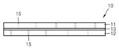
도 1은 미세 유체 소자(10)의 예시적인 구조를 개략적으로 보이는 정면도이다. 도 1을 참조하면, 미세 유체 소자(10)는 예를 들어 얇고 투명한 기판 상에 시료 또는 공기의 유입/유출을 위한 다수의 홀(15), 시료의 화학적/생물학적 반응이 일어나는 다수의 반응 챔버(14), 시료가 이동하는 통로인 다수의 미세 유로(16), 시료의 흐름을 원하는 위치로 정확하게 제어하기 위한 다수의 미세한 밸브(17) 등을 가질 수 있다. 다수의 홀(15)들 중에는 시료만이 유입/유출하는 홀과 밸브(17)를 제어하기 위한 공기만이 유입/유출하는 홀들이 개별적으로 존재할 수도 있다. 밸브(17)는 미세 유로(16) 내에 형성되어 있으며, 미세 유로(16) 내에서 시료를 통과시키거나 차단한다.1 is a front view schematically showing an exemplary structure of a
이러한 밸브(17)는 얇은 폴리머 필름으로 이루어질 수 있다. 도 2는 도 1의 예시적인 미세 유체 소자(10)에서 미세 유로(16) 내에 밸브(17)를 배치하기 위하여 제안된 미세 유체 소자(10)의 개략적인 단면도이다. 도 2의 단면도를 참조하면, 미세 유체 소자(10)는 투명한 제 1 기판(11)과 제 2 기판(12), 상기 제 1 기판(11)과 제 2 기판(12) 사이에 배치된 얇은 폴리머 필름(13)을 구비할 수 있다. 비록 도 2에는 홀(15)만이 도시되어 있지만, 제 1 기판(11)과 제 2 기판(12)에는 각각 개별적으로 다수의 홀(15), 미세 유로(16) 등이 형성되어 있을 수 있다.The
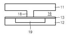
도 3은 도 1의 미세 유체 소자(10)의 미세 유로(16) 내에 형성될 수 있는 미세한 밸브(17)의 단면도를 예시적으로 도시하고 있다. 도 3의 단면도를 참조하면, 제 1 기판(11)에 형성된 미세 유로(16) 내에 밸브 시트(valve seat)(18)가 돌출하여 형성되어 있다. 또한, 제 2 기판(12)에서 밸브 시트(18)와 대응하는 위치에는 제 2 기판(12)을 에칭하여 형성된 빈 공간(19)이 마련되어 있다. 상기 공간(19)과 밸브 시트(18)는 제 1 기판(11)과 제 2 기판(12) 사이의 폴리머 필름(13)에 의해 분리되어 있으며, 상기 폴리머 필름(13)과 각각 접하고 있다. 여기서, 상기 미세 유로(16)는 시료가 유입/유출되는 홀(15)과 연결되어 있을 수 있으며, 공간(19)은 공기가 유입/유출되는 홀(15)과 연결되어 있을 수 있다.FIG. 3 exemplarily shows a cross-sectional view of a
개시된 밸브(17)의 구조에서, 공간(19)을 통해 진공을 인가하며, 얇은 폴리머 필름(13)이 상기 공간(19)을 향해 당겨지면서 미세 유로(16)가 열리게 된다. 그러면 홀(15)을 통해 유입된 시료가 미세 유로(16)를 통해 특정한 위치로 흐를 수 있게 된다. 또한, 공간(19)을 통해 공압을 인가하게 되면, 폴리머 필름(13)이 밸브 시트(18)를 향해 밀리면서 미세 유로(16)가 닫히게 된다. 이에 따라 시료의 흐름이 멈추게 될 수 있다.In the structure of the disclosed valve 17 a vacuum is applied through the
그런데 미세 유체 소자(10)를 제조한 후에 오랫동안 사용하지 않을 경우, 시간이 흐름에 따라 폴리머 필름(13)이 화학적 또는 물리적 반응에 의해 자연적으로 밸브 시트(18)의 표면에 접착될 수 있다. 이러한 현상이 발생할 경우, 미세 유체 소자(10)의 동작시에 밸브(17)가 정상적으로 개폐되지 않을 수 있다. 이를 방지하기 위해 밸브 시트(18)의 표면에만 표면 에너지(surface energy)가 낮은 재료를 코팅할 수도 있지만, 제 1 기판(11) 상의 특정 영역, 즉 밸브 시트(18)의 표면에만 선택적으로 코팅하는 것이 어려울 수도 있다.However, when the
따라서, 미세 유체 소자(10)를 제조한 직후에 및/또는 미세 유체 소자(10)를 사용하기 직전에, 밸브(17)가 안정적으로 동작할 수 있도록 미세 유체 소자(10)를 초기화시키는 것이 필요할 수 있다. 이러한 점에서, 미세 유체 소자(10)의 초기화는 밸브 시트(18)의 표면에 자연적으로 부착된 폴리머 필름(13)이 그로부터 떨어지도록 하는 것이라고 볼 수 있다.It is therefore necessary to initialize the
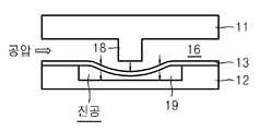
도 4는 미세 유체 소자(10)의 초기화시에 도 3에 도시된 밸브(17)를 개방하는 동작을 개략적으로 나타내는 단면도이다. 도 4를 참조하면, 제 1 기판(11) 상의 미세 유로(16)를 통해 공압을 인가하는 동시에, 제 2 기판(12) 상의 공간(19)을 통해 진공을 인가한다. 이러한 미세 유체 소자(10)의 초기화시에는 제 1 기판(11) 상으로 아직 시료를 유입시키지 않은 상태이므로, 미세 유로(16)를 통해 공압을 추가적으로 인가하는 것이 가능하다. 따라서 제 2 기판(12) 상의 공간(19)으로 인가된 진공만으로는 밸브 시트(18)의 표면으로부터 떨어지지 않을 수도 있는 폴리머 필름(13)도 초기화 동작시에 확실히 떨어지도록 할 수 있다. 이때, 폴리머 필름(13)이 밸브 시트(18)의 표면으로부터 떨어질 때까지 공압 또는 진공을 증가시키는 것도 가능하다. 이렇게 미세 유체 소자(10)를 초기화함으로써, 이후의 미세 유체 소자(10)의 사용시에 밸브(17) 동작의 신뢰성을 향상시킬 수 있다.4 is a cross-sectional view schematically showing the operation of opening the
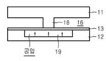
폴리머 필름(13)이 밸브 시트(18)의 표면으로부터 떨어진 후에는, 도 5에 도시된 바와 같이, 공간(19)으로 공압을 인가하여 밸브(17)를 차단하는 동작을 수행할 수도 있다. 또한, 일정한 시간 동안 또는 일정한 횟수 동안 도 4 및 도 5의 초기화 동작을 반복하는 것도 가능하다.After the
한편, 미세 유체 소자(10)의 이러한 초기화 동작을 신속하게 수행하기 위해서는, 폴리머 필름(13)을 밸브 시트(18)의 표면으로부터 떨어뜨리는 작업을 미세 유체 소자(10) 내의 모든 밸브(17)들에 대해 한꺼번에 수행하는 것이 유리하다. 이를 위해서는, 밸브(17)들과 관련된 다수의 홀(15)들을 통해 한꺼번에 공압 또는 진공을 인가할 필요가 있다. 따라서, 미세 유체 소자(10) 내의 밸브(17)들과 관련된 모든 홀(15)들에 연결되어 이들을 통해 한꺼번에 공압 또는 진공을 인가하도록 하는 미세 유체 소자 초기화 장치를 사용할 경우, 미세 유체 소자(10)의 초기화 동작이 간편하게 이루어질 수 있다.In order to quickly perform this initialization operation of the
도 6a 및 도 6b는 미세 유체 소자의 초기화를 위한 미세 유체 소자 초기화 장치(20)의 한 예를 개략적으로 도시하는 사시도로서, 도 6a는 미세 유체 소자 초기화 장치(20)의 하부 지그(jig)(21)를 도시하고 있으며, 도 6b는 미세 유체 소자 초기화 장치(20)의 상부 지그(22)를 도시하고 있다. 도 6a 및 도 6b를 참조하면, 미세 유체 소자 초기화 장치(20)는 미세 유체 소자(10)를 사이에 두고 서로 결합하는 하부 지그(21)와 상부 지그(22)를 구비한다. 하부 및 상부 지그(21,22)의 표면의 중앙부에는 미세 유체 소자(10)가 안착되기 위한 안착부(25,26)가 각각 형성되어 있다. 또한, 하부 지그(21)의 표면에서 안착부(25) 바깥쪽으로는 결합홈(23)이 설치되어 있으며, 상부 지그(22)의 표면에서 안착부(26) 바깥쪽으로는 결합폴(24)이 설치되어 있다. 따라서, 미세 유체 소자(10)를 사이에 두고 하부 지그(21)의 결합홈(23)에 상부 지그(22)의 결합폴(24)을 끼워 하부 지그(21)와 상부 지그(22)를 결합시키면, 미세 유체 소자(10)는 하부와 상부의 안착부(25,26)에 안정적으로 배치될 수 있다.6A and 6B are perspective views schematically showing an example of a microfluidic
또한, 미세 유체 소자(10)의 홀(15)을 통해 밸브(17) 내에 공압 또는 진공을 인가하기 위하여 각각의 안착부(25,26)의 표면에는 다수의 공압홀(27,28)들이 형성되어 있다. 예컨대, 하부 지그(21)의 안착부(25)에 있는 공압홀(27)들의 위치는 미세 유체 소자(10)의 제 1 기판(11) 상에 형성된 홀(15)들의 위치와 대응할 수 있다. 또한, 상부 지그(22)의 안착부(26)에 있는 공압홀(28)들의 위치는 미세 유체 소자(10)의 제 2 기판(12) 상에 형성된 홀(15)들의 위치와 대응할 수 있다. 여기서 상기 공압홀(27,28)들은 미세 유체 소자(10)의 모든 홀(15)들과 대응할 필요는 없으며, 설계에 따라서는 단지 밸브(17)의 개폐와 관련된 홀(15)들에만 대응하도록 형성될 수도 있다.A plurality of
그리고, 하부 지그(21)와 상부 지그(22)의 측면에는, 진공 펌프 또는 공압 펌프와 연결되어 공압홀(27,28)들을 통해 미세 유체 소자(10)에 진공 및/또는 공압을 인가할 수 있도록 하는 공압 포트(29a, 29b, 29c)들이 배치되어 있다. 예를 들어, 하부 지그(21)의 제 1 공압 포트(29a)는 공압 펌프와 연결될 수 있으며, 상부 지그(21)의 제 2 공압 포트(29b)는 공압 펌프와 연결되고, 제 3 공압 포트(29c)는 진공 펌프와 연결될 수 있다. 그러면, 도 4에 도시된 바와 같이 밸브(17)를 개방하는 초기화 동작시에, 제 1 공압 포트(29a)를 통해 제 1 기판(11) 내의 유로(16)에 공압을 인가하고, 제 3 공압 포트(29c)를 통해 제 2 기판(12) 내의 공간(19)에 진공을 인가할 수 있다. 또한, 도 5에 도시된 바와 같이 밸브(17)를 닫는 초기화 동작시에, 제 2 공압 포트(29b)를 통해 제 2 기판(12) 내의 공간(19)에 공압을 인가할 수도 있다. 한편, 도면에는 상기 공압 포트(29a, 29b, 29c)들이 하부 지그(21)와 상부 지그(22)의 측면에 각각 배치된 것으로 도시되어 있으나, 그 위치는 설계 에 따라 변경될 수도 있다. 예를 들어, 하부 지그(21)와 상부 지그(22)의 외측 전면에 공압 포트(29a, 29b, 29c)들이 배치되는 것도 가능하다.Vacuum and / or pneumatic pressure can be applied to the
상술한 바와 같이 미세 유체 소자 초기화 장치(20)는 지그의 형태로 제작될 수 있다. 이 경우, 미세 유체 소자 초기화 장치(20)는 미세 유체 소자(10)와는 별도의 장치로서 존재한다. 또한, 미세 유체 소자 초기화 장치(20)는 상기 미세 유체 소자(10)를 이용하여 시료를 분석하고 관찰하는 분석 시스템과도 별도로 휴대가 가능하도록 제작될 수도 있다. 그러면, 미세 유체 소자(10)의 제작 직후에 미세 유체 소자(10)를 지그 형태의 초기화 장치(20)에 장착하여 초기화한 후에 사용자에게 배포하거나, 또는 최종 사용자가 미세 유체 소자(10)를 사용하기 직전에 지그 형태의 초기화 장치(20)에 장착하여 초기화한 후에 이를 시료 분석 시스템에 장착하여 시료 분석을 수행할 수도 있다.As described above, the microfluidic
그러나 도 6a 및 도 6b에 도시된 형태의 미세 유체 소자 초기화 장치(20)를 미세 유체 소자(10)에 또는 그의 시료 분석 시스템에 일체화하는 것도 가능하다. 그러면 미세 유체 소자(10)의 초기화가 더욱 간편하게 수행될 수도 있다.However, it is also possible to integrate the microfluidic
예를 들어, 도 6a 및 도 6b에 도시된 형태로 미세 유체 소자 패키지를 제작할 수도 있다. 즉, 도 6a 및 도 6b에 도시된 것과 같은 공압홀(27,28)과 공압 포트(29a,29b,29c)를 구비하는 하부 및 상부 패키지 기판 사이에 미세 유체 소자(10)를 배치하고, 이들을 하나의 패키지 제품으로서 완전히 결합시킬 수 있다. 이렇게 미세 유체 소자(10)와 그의 초기화 장치가 하나의 제품으로서 함께 일체화된 미세 유체 소자 패키지가 제공되는 경우, 사용자는 별도의 초기화 장치 없이도 미세 유 체 소자(10)의 초기화가 가능하다. 또한 제작자도 제작 직후에 미세 유체 소자(10)를 별도의 초기화 장치로 이송할 필요 없이 제작된 미세 유체 소자(10)를 바로 초기화하는 것이 가능하다.For example, a microfluidic device package may be manufactured in the form shown in Figs. 6A and 6B. That is, the
이렇게 미세 유체 소자(10)와 미세 유체 소자 초기화 장치(20)를 하나로 패키지화한 경우에, 하부 지그(21)의 제 1 공압 포트(29a)는 공압뿐만 아니라 미세 유체 시료의 유입 포트 역할을 할 수도 있다. 미세 유체 소자(10)의 초기화시에 제 1 기판(11) 상에 형성된 홀(15)은 공압이 유입되는 공압 유입구의 역할을 하지만, 시료의 분석시에는 미세 유체 시료가 유입되는 시료 유입구의 역할을 한다. 따라서 미세 유체 소자(10)가 초기화된 후에 실제 시료 분석에 사용되는 경우, 상기 제 1 공압 포트(29a)를 통해서 시료가 유입되도록 할 수도 있다. 이러한 방식으로 제 1 공압 포트(29a)가 공압 포트와 시료 유입 포트의 역할을 공유할 수도 있지만, 별도의 시료 유입 포트를 하부 지그(21)에 마련하는 것도 가능하다. 즉, 하부 지그(21)에는 도 6a에 도시된 제 1 공압 포트(29a) 이외에도 시료의 유입을 위한 적어도 하나의 포트(도시되지 않음)가 더 설치될 수 있다. 마찬가지 이유로, 상부 지그(22)에는 도 6b에 도시된 제 2 공압 포트(29b)와 제 3 공압 포트(29c) 이외에 적어도 하나의 포트(도시되지 않음)가 추가적으로 설치될 수 있다. 또한, 시료의 유입을 위한 이러한 추가적인 포트들은 미세 유체 소자 패키지에만 적용되는 것이 아니라, 상술한 미세 유체 소자 초기화 장치(20)에도 적용될 수 있다.When the
도 6a 및 도 6b에 도시된 지그 형태의 미세 유체 소자 초기화 장치(20)는, 또한 미세 유체 소자(10)의 시료 분석 시스템에 일체화될 수도 있다. 예를 들어, 시료 분석 시스템의 스테이션(station) 위에 도 6a 및 도 6b에 도시된 것과 같은 미세 유체 소자 초기화 장치(20)를 장착할 수 있다. 그러면, 사용자는 시료의 분석 전에 시료 분석 시스템 위에서 직접 미세 유체 소자(10)를 초기화하고, 그 자리에서 시료의 분석까지 수행할 수 있다. 이렇게 미세 유체 소자 초기화 장치(20)를 시료 분석 시스템에 일체화하는 경우에도, 제 1 내지 제 3 공압 포트(29a, 29b, 29c)들 이외에 시료의 유입을 위한 상술한 추가적인 포트들이 하부 지그(21) 및 상부 지그(22)에 각각 더 마련될 수 있다.The microfluidic
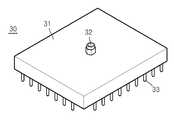
한편, 도 7은 미세 유체 소자(10)를 초기화하기 위한 보다 간이한 초기화 장치로서 멀티-니들 장치(multi-needle apparatus)(30)를 개략적으로 도시하고 있다. 도 7을 참조하면, 멀티-니들 장치(30)는 기판(31), 상기 기판(31)의 하부에 마련된 다수의 니들(33), 및 진공 펌프 또는 공압 펌프와 연결되어 상기 니들(33)을 통해 미세 유체 소자(10)에 진공 및/또는 공압을 인가할 수 있도록 하는 공압 포트(32)를 구비할 수 있다. 도 7에는 공압 포트(32)가 기판(31)의 상부에 배치된 것으로 도시되어 있지만, 기판(31)의 측면에 배치되는 것도 가능하다. 또한, 도 7에는 단지 하나의 공압 포트(32)만이 도시되어 있지만, 예를 들어 2개 또는 그 이상의 공압 포트(32)가 배치되는 것도 가능하다. 다수의 니들(33)은 미세 유체 소자(10)에 형성된 다수의 홀(15)들의 위치와 대응하도록 어레이를 이룰 수 있다. 특히, 상기 니들(33)의 어레이는 미세 유체 소자(10)의 모든 홀(15)들과 대응할 필요는 없으며 단지 밸브(17)의 개폐와 관련된 홀(15)들에만 대응하도록 형성될 수도 있다.On the other hand, FIG. 7 schematically shows a
도 7에 도시된 것과 같은 멀티-니들 장치(30)는 미세 유체 소자(10)의 제 1 기판(11)에 형성된 홀(15)들과 제 2 기판(12)에 형성된 홀(15)들에 각각 대응하도록 2개가 하나의 쌍으로 제작될 수 있다. 즉, 미세 유체 소자(10)의 제 1 기판(11) 상에 형성된 홀(15)들과 대응하는 니들(33)들의 어레이를 갖는 멀티-니들 장치와 미세 유체 소자(10)의 제 2 기판(12) 상에 형성된 홀(15)들과 대응하는 니들(33)들의 어레이를 갖는 멀티-니들 장치가 함께 쌍을 이룰 수 있다. 그러면, 미세 유체 소자(10)의 제 1 기판(11)에 형성된 홀(15)들과 제 2 기판(12)에 형성된 홀(15)들에 각각의 대응하는 멀티-니들 장치(30)의 니들(33)들을 각각 끼워 넣은 후, 도 4 및 도 5에 도시된 것과 같은 초기화 작업을 수행할 수 있다.The
지금까지, 본 발명의 이해를 돕기 위하여 미세 유체 소자의 초기화 방법, 미세 유체 소자의 초기화 장치, 및 미세 유체 소자 패키지에 대한 예시적인 실시예가 설명되고 첨부된 도면에 도시되었다. 그러나, 이러한 실시예는 단지 본 발명을 예시하기 위한 것이고 이를 제한하지 않는다는 점이 이해되어야 할 것이다. 그리고 본 발명은 도시되고 설명된 설명에 국한되지 않는다는 점이 이해되어야 할 것이다. 이는 다양한 다른 변형이 본 기술분야에서 통상의 지식을 가진 자에게 일어날 수 있기 때문이다.Up to now, to facilitate understanding of the present invention, exemplary embodiments of a microfluidic device initialization method, a microfluidic device initialization device, and a microfluidic device package have been described and shown in the accompanying drawings. It should be understood, however, that such embodiments are merely illustrative of the present invention and not limiting thereof. And it is to be understood that the invention is not limited to the details shown and described. Since various other modifications may occur to those of ordinary skill in the art.
도 1은 미세 유체 소자의 예시적인 구조를 개략적으로 보이는 정면도이다.1 is a front view schematically showing an exemplary structure of a microfluidic device.
도 2는 도 1에 도시된 미세 유체 소자의 개략적인 단면도이다.2 is a schematic cross-sectional view of the microfluidic device shown in FIG.
도 3은 도 1에 도시된 미세 유체 소자 내에 형성된 미세한 밸브의 단면도이다.3 is a cross-sectional view of a fine valve formed in the microfluidic device shown in FIG.
도 4는 미세 유체 소자의 초기화시에 도 3에 도시된 밸브를 개방하는 동작을 개략적으로 나타내는 단면도이다.4 is a cross-sectional view schematically showing the operation of opening the valve shown in Fig. 3 at the time of initialization of the microfluidic device.
도 5는 미세 유체 소자의 초기화시에 도 3에 도시된 밸브를 차단하는 동작을 개략적으로 나타내는 단면도이다.5 is a cross-sectional view schematically showing the operation of shutting off the valve shown in Fig. 3 when the microfluidic device is initialized.
도 6a 및 도 6b는 미세 유체 소자의 초기화를 위한 미세 유체 소자 초기화 장치의 일 예를 개략적으로 도시하는 사시도이다.6A and 6B are perspective views schematically showing an example of a microfluidic device initialization apparatus for initializing a microfluidic device.
도 7은 미세 유체 소자의 초기화를 위한 멀티-니들 장치를 개략적으로 도시하는 사시도이다.7 is a perspective view schematically showing a multi-needle device for initializing a microfluidic device.
< 도면의 주요 부분에 대한 부호의 설명 >Description of the Related Art
10.....미세 유체 소자11.....제 1 기판10 .....
12.....제 2 기판13.....폴리머 필름12 .....
14.....반응 챔버15.....홀14 .....
16.....미세 유로17.....밸브16 .....
18.....밸브 시트19.....공간18 .....
20.....미세 유체 소자 초기화 장치21.....하부 지그20 ..... microfluidic
22.....상부 지그23.....결합홈22 .....
24.....결합폴25,26.....안착부24 ..... coupling
27,28.....공압홀29a,29b,29c.....공압 포트27,28 .....
30.....멀티-니들 장치31.....기판30 .....
32.....공압 포트33.....니들32 .....
Claims (21)
Translated fromKoreanPriority Applications (2)
| Application Number | Priority Date | Filing Date | Title |
|---|---|---|---|
| KR1020090102821AKR101569836B1 (en) | 2009-10-28 | 2009-10-28 | Microfluidic device initialization method microfluidic device initialization apparatus and microfluidic device package |
| US12/757,374US8636033B2 (en) | 2009-10-28 | 2010-04-09 | Microfluidic device initialization method, microfluidic device initialization apparatus and microfluidic device package |
Applications Claiming Priority (1)
| Application Number | Priority Date | Filing Date | Title |
|---|---|---|---|
| KR1020090102821AKR101569836B1 (en) | 2009-10-28 | 2009-10-28 | Microfluidic device initialization method microfluidic device initialization apparatus and microfluidic device package |
Publications (2)
| Publication Number | Publication Date |
|---|---|
| KR20110046019A KR20110046019A (en) | 2011-05-04 |
| KR101569836B1true KR101569836B1 (en) | 2015-11-17 |
Family
ID=43897360
Family Applications (1)
| Application Number | Title | Priority Date | Filing Date |
|---|---|---|---|
| KR1020090102821AActiveKR101569836B1 (en) | 2009-10-28 | 2009-10-28 | Microfluidic device initialization method microfluidic device initialization apparatus and microfluidic device package |
Country Status (2)
| Country | Link |
|---|---|
| US (1) | US8636033B2 (en) |
| KR (1) | KR101569836B1 (en) |
Families Citing this family (7)
| Publication number | Priority date | Publication date | Assignee | Title |
|---|---|---|---|---|
| US20130032235A1 (en)* | 2011-08-02 | 2013-02-07 | Teledyne Dalsa Semiconductor, Inc. | Integrated microfluidic check valve and device including such a check valve |
| KR101399511B1 (en)* | 2012-12-28 | 2014-05-27 | 재단법인대구경북과학기술원 | Apparatus for controlling fluid using micro fluid chip |
| CN105828944B (en) | 2013-11-22 | 2018-02-02 | 瑞尼克斯有限公司 | Without channel pump and its method and application |
| JP1565699S (en)* | 2016-01-12 | 2016-12-19 | ||
| USD800336S1 (en)* | 2016-07-13 | 2017-10-17 | Precision Nanosystems Inc | Microfluidic cartridge |
| USD812242S1 (en)* | 2016-07-13 | 2018-03-06 | Precision Nanosystems Inc | Microfluidic cartridge |
| GB2555816A (en)* | 2016-11-10 | 2018-05-16 | Natural Environment Res Council | Analyser |
Citations (1)
| Publication number | Priority date | Publication date | Assignee | Title |
|---|---|---|---|---|
| US20050201901A1 (en)* | 2004-01-25 | 2005-09-15 | Fluidigm Corp. | Crystal forming devices and systems and methods for using the same |
Family Cites Families (20)
| Publication number | Priority date | Publication date | Assignee | Title |
|---|---|---|---|---|
| US6167910B1 (en)* | 1998-01-20 | 2001-01-02 | Caliper Technologies Corp. | Multi-layer microfluidic devices |
| US7867776B2 (en)* | 2001-03-02 | 2011-01-11 | Caliper Life Sciences, Inc. | Priming module for microfluidic chips |
| US7069952B1 (en)* | 2001-11-14 | 2006-07-04 | Caliper Life Sciences, Inc. | Microfluidic devices and methods of their manufacture |
| US20040109793A1 (en)* | 2002-02-07 | 2004-06-10 | Mcneely Michael R | Three-dimensional microfluidics incorporating passive fluid control structures |
| US6814859B2 (en)* | 2002-02-13 | 2004-11-09 | Nanostream, Inc. | Frit material and bonding method for microfluidic separation devices |
| EP1545780B1 (en)* | 2002-09-06 | 2007-02-28 | Epigem Limited | Modular microfluidic system |
| US20040092033A1 (en)* | 2002-10-18 | 2004-05-13 | Nanostream, Inc. | Systems and methods for preparing microfluidic devices for operation |
| US20050266582A1 (en)* | 2002-12-16 | 2005-12-01 | Modlin Douglas N | Microfluidic system with integrated permeable membrane |
| US6807892B2 (en) | 2002-12-30 | 2004-10-26 | Xerox Corporation | Pneumatic actuator with elastomeric membrane and low-power electrostatic flap valve arrangement |
| AU2003303594A1 (en)* | 2002-12-30 | 2004-07-29 | The Regents Of The University Of California | Methods and apparatus for pathogen detection and analysis |
| JP2005007529A (en)* | 2003-06-19 | 2005-01-13 | Dainippon Screen Mfg Co Ltd | Micro fluid device and manufacturing method of micro fluid device |
| US20060013731A1 (en)* | 2004-03-26 | 2006-01-19 | Phil Stout | Microfluidic system with feedback control |
| WO2006015308A2 (en)* | 2004-07-29 | 2006-02-09 | California Institute Of Technology | Modular microfluidic packaging system |
| JP2006187684A (en)* | 2004-12-28 | 2006-07-20 | Fuji Xerox Co Ltd | Microfluid device |
| US8361410B2 (en)* | 2005-07-01 | 2013-01-29 | Honeywell International Inc. | Flow metered analyzer |
| KR20070052958A (en) | 2005-11-18 | 2007-05-23 | 주식회사 엘지생명과학 | Plastic chips for PCR with ON-chip polymer valves |
| US7766033B2 (en)* | 2006-03-22 | 2010-08-03 | The Regents Of The University Of California | Multiplexed latching valves for microfluidic devices and processors |
| US20070278100A1 (en)* | 2006-05-30 | 2007-12-06 | Honda Motor Co., Ltd. | Apparatus for controlling flow rate in micro-flow path, microchip apparatus comprising flow-rate-controlling apparatus, and flow-rate-controlling method |
| ES2533901T3 (en)* | 2006-08-10 | 2015-04-15 | California Institute Of Technology | Microfluidic valves with floating element and manufacturing procedure |
| JP4677969B2 (en)* | 2006-10-06 | 2011-04-27 | 株式会社日立プラントテクノロジー | Microreactor |
- 2009
- 2009-10-28KRKR1020090102821Apatent/KR101569836B1/enactiveActive
- 2010
- 2010-04-09USUS12/757,374patent/US8636033B2/enactiveActive
Patent Citations (1)
| Publication number | Priority date | Publication date | Assignee | Title |
|---|---|---|---|---|
| US20050201901A1 (en)* | 2004-01-25 | 2005-09-15 | Fluidigm Corp. | Crystal forming devices and systems and methods for using the same |
Also Published As
| Publication number | Publication date |
|---|---|
| KR20110046019A (en) | 2011-05-04 |
| US20110094591A1 (en) | 2011-04-28 |
| US8636033B2 (en) | 2014-01-28 |
Similar Documents
| Publication | Publication Date | Title |
|---|---|---|
| KR101569836B1 (en) | Microfluidic device initialization method microfluidic device initialization apparatus and microfluidic device package | |
| CN108443579B (en) | A microvalve and microfluidic chip capable of controlling liquid flow | |
| US9901925B2 (en) | Micro-fluidic device | |
| US7892493B2 (en) | Fluid sample transport device with reduced dead volume for processing, controlling and/or detecting a fluid sample | |
| US11260389B2 (en) | Disposable diagnostic device with vented priming fluid passage for volumetric control of sample and reagents and method of performing a diagnosis therewith | |
| US8425863B2 (en) | Micro fluidic device | |
| US8123192B2 (en) | Control arrangement for microfluidic devices and related methods and systems | |
| US8444933B2 (en) | Microfluidic device and method of manufacturing the same | |
| TWI641823B (en) | Integrated fluidic module and method of regulating fluid operations in multi-fluid-system by using the same | |
| US7727472B2 (en) | Chemical analysis apparatus and chemical analysis cartridge | |
| KR101869184B1 (en) | Rotatable cartridge for measuring a property of a biological sample | |
| US20080145286A1 (en) | Microfluidic devices and related methods and systems | |
| KR100618320B1 (en) | Fluid transfer device and disposable chip with same | |
| KR101799519B1 (en) | Microvalve device and method of fabricating the same | |
| WO2015185226A1 (en) | Rotatable cartridge for analyzing a biological sample | |
| JP2006087336A (en) | Cell analyzer | |
| CN209354751U (en) | A microvalve that controls the flow of liquids | |
| CN113441194B (en) | Microfluidic detection chip | |
| KR101830759B1 (en) | Smart pipette for on-site whole blood analysis | |
| KR20180102371A (en) | Micro valve appratus for bio chip | |
| JP2004361205A (en) | Micro reactor | |
| CN106999935A (en) | The method of microfluid system and analysis sample solution and the method for manufacturing the microfluid system for analyzing sample solution | |
| Schneider et al. | A novel metering component for volume management in flow-based microfluidic biochips | |
| US20230094429A1 (en) | Cartridge and liquid handling device | |
| WO2013066145A1 (en) | A microfluidic system and method thereof |
Legal Events
| Date | Code | Title | Description |
|---|---|---|---|
| PA0109 | Patent application | Patent event code:PA01091R01D Comment text:Patent Application Patent event date:20091028 | |
| PG1501 | Laying open of application | ||
| A201 | Request for examination | ||
| PA0201 | Request for examination | Patent event code:PA02012R01D Patent event date:20140529 Comment text:Request for Examination of Application Patent event code:PA02011R01I Patent event date:20091028 Comment text:Patent Application | |
| E902 | Notification of reason for refusal | ||
| PE0902 | Notice of grounds for rejection | Comment text:Notification of reason for refusal Patent event date:20150317 Patent event code:PE09021S01D | |
| E701 | Decision to grant or registration of patent right | ||
| PE0701 | Decision of registration | Patent event code:PE07011S01D Comment text:Decision to Grant Registration Patent event date:20150921 | |
| GRNT | Written decision to grant | ||
| PR0701 | Registration of establishment | Comment text:Registration of Establishment Patent event date:20151111 Patent event code:PR07011E01D | |
| PR1002 | Payment of registration fee | Payment date:20151112 End annual number:3 Start annual number:1 | |
| PG1601 | Publication of registration | ||
| FPAY | Annual fee payment | Payment date:20181024 Year of fee payment:4 | |
| PR1001 | Payment of annual fee | Payment date:20181024 Start annual number:4 End annual number:4 | |
| PR1001 | Payment of annual fee | Payment date:20201019 Start annual number:6 End annual number:6 | |
| PR1001 | Payment of annual fee | Payment date:20211025 Start annual number:7 End annual number:7 | |
| PR1001 | Payment of annual fee | Payment date:20221021 Start annual number:8 End annual number:8 | |
| PR1001 | Payment of annual fee | Payment date:20231020 Start annual number:9 End annual number:9 | |
| PR1001 | Payment of annual fee | Payment date:20241021 Start annual number:10 End annual number:10 |