KR101568046B1 - Footrest device for rear passengers - Google Patents
Footrest device for rear passengersDownload PDFInfo
- Publication number
- KR101568046B1 KR101568046B1KR1020090067176AKR20090067176AKR101568046B1KR 101568046 B1KR101568046 B1KR 101568046B1KR 1020090067176 AKR1020090067176 AKR 1020090067176AKR 20090067176 AKR20090067176 AKR 20090067176AKR 101568046 B1KR101568046 B1KR 101568046B1
- Authority
- KR
- South Korea
- Prior art keywords
- lead screw
- footrest
- drive motor
- plate
- pipe
- Prior art date
- Legal status (The legal status is an assumption and is not a legal conclusion. Google has not performed a legal analysis and makes no representation as to the accuracy of the status listed.)
- Expired - Fee Related
Links
Images


Classifications
- B—PERFORMING OPERATIONS; TRANSPORTING
- B60—VEHICLES IN GENERAL
- B60N—SEATS SPECIALLY ADAPTED FOR VEHICLES; VEHICLE PASSENGER ACCOMMODATION NOT OTHERWISE PROVIDED FOR
- B60N3/00—Arrangements or adaptations of other passenger fittings, not otherwise provided for
- B60N3/06—Arrangements or adaptations of other passenger fittings, not otherwise provided for of footrests
- B60N3/063—Arrangements or adaptations of other passenger fittings, not otherwise provided for of footrests with adjustment systems
- A—HUMAN NECESSITIES
- A47—FURNITURE; DOMESTIC ARTICLES OR APPLIANCES; COFFEE MILLS; SPICE MILLS; SUCTION CLEANERS IN GENERAL
- A47C—CHAIRS; SOFAS; BEDS
- A47C16/00—Stand-alone rests or supports for feet, legs, arms, back or head
- A47C16/02—Footstools; Foot-rests; Leg-rests
- A47C16/025—Footstools; Foot-rests; Leg-rests adjustable, swivelling, rocking
- B—PERFORMING OPERATIONS; TRANSPORTING
- B60—VEHICLES IN GENERAL
- B60N—SEATS SPECIALLY ADAPTED FOR VEHICLES; VEHICLE PASSENGER ACCOMMODATION NOT OTHERWISE PROVIDED FOR
- B60N2/00—Seats specially adapted for vehicles; Arrangement or mounting of seats in vehicles
- B60N2/02—Seats specially adapted for vehicles; Arrangement or mounting of seats in vehicles the seat or part thereof being movable, e.g. adjustable
- B60N2/0224—Non-manual adjustments, e.g. with electrical operation
- B60N2/02246—Electric motors therefor
- B60N2/02253—Electric motors therefor characterised by the transmission between the electric motor and the seat or seat parts
Landscapes
- Engineering & Computer Science (AREA)
- Transportation (AREA)
- Mechanical Engineering (AREA)
- Aviation & Aerospace Engineering (AREA)
- Passenger Equipment (AREA)
- Chairs For Special Purposes, Such As Reclining Chairs (AREA)
Abstract
Translated fromKoreanDescription
Translated fromKorean본 발명은 뒷좌석 승객의 편의성 향상을 위해 차량에 마련된 뒷좌석 승객용 풋레스트 장치에 관한 기술이다.The present invention relates to a rear seat passenger footrest device provided in a vehicle for improving the convenience of a rear seat passenger.
일반적인 승용 차량의 경우, 후방시트에 착석한 뒷좌석 승객은 전방시트와의 공간이 충분하지 않기 때문에 발을 편하게 뻗지 못할 뿐만 아니라 발을 올려놓을 만한 별도의 거치대도 마련되어 있지 않아서 장거리 이동시 피로감이 가중되는 문제점이 있다.In the case of a general passenger vehicle, a rear-seat passenger seated on the rear seat can not easily extend his / her foot since the space between the seat and the front seat is not sufficient, and there is no separate stand for placing the foot. .
이를 해결하기 위한 방안으로 뒷좌석 승객이 발을 올려놓을 수 있는 풋레스트 장치를 전방시트에 설치하고 있는데, 대부분의 풋레스트 장치들은 뒷좌석 승객이 발을 올려놓게 되는 플레이트의 작동이 사용자에 의한 수동 조작이 주를 이루고 있는 실정이어서 사용에 따른 불편함이 있었다.In order to solve this problem, a footrest device is mounted on the front seat for the rear seat passengers to put their feet on. The most of the footrest devices are those in which the operation of the plate in which the rear passengers put their feet is manually operated And it was inconvenient for the use because it is the state which is the main state.
본 발명은, 뒷좌석 승객이 발을 올려놓게 되는 플레이트의 작동이 간단한 스위치의 조작으로 자동 작동이 가능하도록 함으로써, 사용자의 편의성을 향상시킬 수 있도록 하는 뒷좌석 승객용 풋레스트 장치를 제공함에 그 목적이 있다.SUMMARY OF THE INVENTION It is an object of the present invention to provide a footrest device for a passenger in a rear seat that enables the operation of a plate on which a foot of a rear seat passenger is placed to be automatically operated by operation of a simple switch, .
상기와 같은 목적을 달성하기 위한 본 발명 뒷좌석 승객용 풋레스트 장치는, 시트백프레임과 연접하는 시트쿠션프레임의 양쪽 측면을 가로질러서 양단이 상기 시트쿠션프레임에 고정 설치되는 고정파이프와; 상기 시트쿠션프레임과 연접하는 상기 시트백프레임의 양쪽 측면에 고정 결합되면서 상기 시트백프레임의 양쪽 측면사이에 위치하는 중간부분이 시트백의 후방으로 돌출되도록 절곡 형성된 베이스 플레이트와; 상기 고정파이프에 결합된 모터브라켓에 상기 고정파이프의 원주방향을 따라 회전 가능하도록 결합되어 설치되면서 스위치 조작시 차량의 배터리로부터 전원을 인가받아 정,역회전 구동하는 구동모터와; 상기 시트백의 후방 하측에 세워져서 보관되는 상태 및 후방시트를 향해 회전하여 펼쳐지는 동작이 가능하도록 상기 베이스 플레이트를 관통한 힌지파이프의 양단에 한쪽 끝부분이 회전 가능하게 결합되어 설치된 풋레스트 플레이트와; 상기 구동모터의 동력으로 상기 풋레스트 플레이트의 작동이 가능하도록 상기 구동모터와 상기 풋레스트 플레이트를 연결하여 설치된 동력전달 조립체;를 포함하는 것을 특징으로 한다.In order to accomplish the above object, there is provided a rear seat passenger footrest device comprising: a fixed pipe having opposite ends across opposite side surfaces of a seat cushion frame connected to a seatback frame, the both ends of which are fixed to the seat cushion frame; A base plate fixedly coupled to both side surfaces of the seat back frame and connected to the seat cushion frame, the intermediate portion being positioned between both side surfaces of the seat back frame, the base plate being bent to protrude rearward of the seat back; A drive motor coupled to the motor bracket coupled to the stationary pipe so as to be rotatable along the circumferential direction of the stationary pipe and configured to receive power from a battery of the vehicle during a switch operation to perform forward and reverse rotation; A footrest plate having one end rotatably coupled to both ends of a hinge pipe passing through the base plate so as to be able to be rotated and opened toward a rear seat while being raised and stored at a rear lower side of the seatback; And a power transmission assembly connected to the drive motor and the footrest plate to enable operation of the footrest plate by the power of the drive motor.
본 발명에 의하면, 풋레스트 플레이트의 동작이 시트백에 설치된 스위치에 의해 자동으로 진행됨으로써 사용자의 편의성이 크게 향상되고, 아울러 내구성이 높은 리드스크루를 사용함으로 인해 작동불량에 따른 고장의 염려가 없는 효과가 있다.According to the present invention, since the operation of the footrest plate is automatically advanced by the switch provided in the seat back, the convenience of the user is greatly improved. Moreover, since the lead screw having high durability is used, there is no fear of failure due to malfunction have.
이하 본 발명의 실시예를 첨부된 예시도면을 참조로 상세히 설명한다.Hereinafter, embodiments of the present invention will be described in detail with reference to the accompanying drawings.
본 발명에 따른 뒷좌석 승객용 풋레스트 장치는 도 1 내지 도 9에 도시된 바와 같이 시트백(2)의 후방 하측에 설치되는 구성이다.1 to 9, the rear seat passenger footrest device according to the present invention is installed at the rear lower side of the
차량의 시트는 시트쿠션(1)과 시트백(2) 및 헤드레스트를 포함하여 구성되는데, 상기 시트쿠션(1)은 시트쿠션프레임(3)에 의해 골격을 이루고, 상기 시트백(2)은 시트백프레임(4)에 의해 골격을 이루게 된다.A seat of a vehicle includes a seat cushion 1, a seat back 2 and a headrest. The seat cushion 1 is formed by a
상기 시트백프레임(4)과 연접하는 상기 시트쿠션프레임(3)에는 고정파이프(11)가 설치되는데, 상기 고정파이프(11)는 상기 시트쿠션프레임(3)의 양쪽 측면을 가로지르면서 양단이 상기 시트쿠션프레임(3)을 관통한 상태로 고정 설치된다.A
상기 시트쿠션프레임(3)과 연접하는 상기 시트백프레임(4)에는 베이스 플레이트(13)가 설치되는데, 상기 베이스 플레이트(13)의 양쪽 측면에는 플랜지(13a)가 일체로 형성되어 있고, 상기 플랜지(13a)가 상기 시트백프레임(4)의 양쪽 측면에 덧대여진 상태로 용접 결합되어 설치된다.A
그리고, 상기 플랜지(13a) 사이의 중간부분(13b)은 상기 시트백(2)의 후방으로 돌출된 형상을 갖는다.The
상기 고정파이프(11)에는 모터브라켓(15)이 용접 결합되어 설치되고, 상기 모터브라켓(15)에는 구동모터(17)가 결합핀(17a)을 매개로 상기 고정파이프(11)의 원주방향을 따라 회전 가능하도록 결합된다.A
상기 구동모터(17)는 상기 시트백(2)에 장착된 스위치(19)와 전기적으로 연 결되어 있어서, 상기 스위치(19)의 조작방향에 따라 차량의 배터리(미도시)로부터 인가되는 전류의 방향이 정방향(시계방향) 또는 역방향(반 시계방향)으로 바뀌어져 인가되며, 이에 따라 상기 구동모터(17)는 정방향 또는 역방향 회전을 하게 된다.The
즉, 상기 구동모터(17)는 상기 스위치(19)가 중립상태일 때 전원이 차단되어 동작하지 않고, 상기 스위치(19)가 한쪽 방향으로 작동할 때 전류의 방향이 정방향으로 인가되어 정방향 회전을 하며, 상기 스위치(21)가 반대쪽 방향으로 작동할 때 전류의 방향이 역방향으로 바뀌어 역방향 회전을 하는 구성인 것이다.That is, when the
상기 베이스 플레이트(13)의 중간부분(13b)에는 힌지파이프(21)가 설치되는데, 상기 힌지파이프(21)는 상기 고정파이프(11)와 평행한 상태로 설치되며, 또한 상기 힌지파이프(21)의 양단은 상기 중간부분(13b)의 수직한 면을 관통하여 상기 중간부분(13b)과 용접 결합되어 설치된다.A
상기 베이스 플레이트(13)의 중간부분(13b)을 관통한 상기 힌지파이프(21)의 양단에는 풋레스트 플레이트(23)의 한쪽 끝부분이 회전 가능하게 결합되어 설치된다.One end of the
즉, 상기 풋레스트 플레이트(23)는 아래면이 개구된 평판형상 직육면체 모양으로 형성되는데, 상기 힌지파이프(21)의 양단은 개구된 아래면을 통해 삽입되어 상기 풋레스트 플레이트(23)의 한쪽 끝부분에 결합되며, 이에 따라 상기 풋레스트 플레이트(23)는 상기 힌지파이프(21)를 중심으로 회전하면서 상기 시트백(2)의 후방 하측에 세워져서 보관되는 상태 및 후방시트를 향해 회전하여 펼쳐지는 동작이 가능하도록 설치되는 구조를 갖게 된다.That is, the
상기 풋레스트 플레이트(23)의 한쪽 끝부분에는 상기 힌지파이프(21)의 양단이 삽입되어 결합될 수 있는 홈이나 또는 구멍이 형성될 수 있다.A groove or a hole can be formed at one end of the
상기 고정파이프(11)와 상기 힌지파이프(21)는 다수개의 보강브라켓(25)을 매개로 연결된 구조로 되어 있으며, 이에 따라 상기 힌지파이프(21)와 상기 베이스 플레이트(13)의 결합강도는 한층 더 강화된 구조를 갖게 된다.The
상기 보강브라켓(25)의 일단에는 상기 고정파이프(11)를 수용하기 위한 유(∪)자 모양 결합홈(25a)이 형성되어 있어서 상기 결합홈(25a)으로 상기 고정파이프(11)를 수용시킨 후 용접 결합되고, 상기 보강브라켓(25)의 타단에는 상기 힌지파이프(21)가 관통되는 결합구멍(25b)이 형성되어 있어서 상기 결합구멍(25b)으로 상기 힌지파이프(21)를 관통시킨 후 용접 결합된다.A U-shaped
한편, 상기 풋레스트 플레이트(23)가 상기 힌지파이프(21)를 중심으로 회전하는 작동은 상기 구동모터(17)의 동력을 전달받아 자동으로 작동하게 된다.Meanwhile, the rotation of the
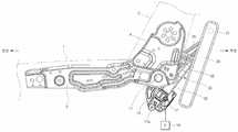
이를 위해, 상기 구동모터(17)와 상기 풋레스트 플레이트(23)는 본 발명 실시예에 따른 동력전달 조립체(30)를 매개로 연결된 구조를 갖게 된다.To this end, the
상기 동력전달 조립체(30)는, 상기 풋레스트 플레이트(23)의 밑면에서 상기 힌지파이프(21)와 평행한 방향으로 서로 떨어져서 고정 설치된 한 쌍의 고정브라켓(31)과, 상기 한 쌍의 고정브라켓(31)에 양단이 관통된 상태로 용접 결합되어 설치된 연결로드(32)와, 일단은 상기 구동모터(17)에 연결되고 타단은 상기 연결로드(32)를 향하도록 설치되어 상기 구동모터(17)의 동력을 전달받아서 축회전하는 리드스크루(33)와, 상기 리드스크루(33)의 축회전시 상기 리드스크루(33)를 따라 왕복 이동하는 리드스크루 너트(34)와, 상기 리드스크루 너트(34)에 일단이 용접 결합되고 상기 연결로드(32)에 타단이 관통된 상태로 용접 결합되어 설치된 리드스크루 브라켓(35)으로 구성된다.The
여기서, 상기 고정브라켓(31)은 수평면과 수직면이 일체로 된 니은(ㄴ)자 단면 모양으로 형성되는데, 상기 수평면은 상기 풋레스트 플레이트(23)의 밑면에 용접 결합되는 면이고, 상기 수직면에는 상기 연결로드(32)가 관통하는 구멍(31a)이 형성된다.Here, the
그리고, 상기 리드스크루 브라켓(35)의 양쪽 테두리는 수직하게 절곡된 수직면으로 되어 있으며, 상기 수직면에 상기 연결로드(32)가 관통하는 구멍(31a)이 형성된다.Both ends of the
또한, 상기 연결로드(32)를 향한 상기 리드스크루(33)의 끝에는 상기 리드스크루 너트(34)의 이동을 구속함으로써 상기 리드스크루(33)로부터 상기 리드스크루 너트(34)의 이탈을 방지하도록 하는 스토퍼너트(36)가 결합되어 설치된다.The end of the
한편, 상기 리드스크루 너트(34)가 상기 구동모터(17)가 있는 일단에서 상기 스토퍼너트(36)가 있는 타단까지 이동하면, 상기 풋레스트 플레이트(23)는 상기 힌지파이프(21)를 중심으로 125도(°) 내지 130도(°)의 각도로 회전하게 되는데, 보다 정확히 말하면 상기 풋레스트 플레이트(23)는 128도(°) 회전하도록 설치된 구성이다.When the
상기 풋레스트 플레이트(23)의 회전각도는 상기 풋레스트 플레이트(23)가 상기 시트백(2)의 후방 하측에 위치한 상태에서 후방시트를 향하여 회전 완료한 상태 의 각도이며, 이때의 회전각도가 128도(°)인 이유는 후방시트를 향해 회전한 상기 풋레스트 플레이트(23)상에 뒷좌석 승객이 발을 올려놓았을 때 가장 편안한 자세를 유지할 수 있기 때문이다.The rotation angle of the
하지만, 상기 회전각도가 모든 종류의 풋레스트 플레이트(23)에 동일하게 적용되는 각도는 아니기 때문에, 다양한 각도로 실시 변경이 가능할 것이다.However, since the angle of rotation is not the same as that applied to all kinds of
이하, 본 발명 실시예의 작용에 대해 설명한다.Hereinafter, the operation of the embodiment of the present invention will be described.
뒷좌석 승객이 사용하지 않는 풋레스트 플레이트(23)는 도 1 내지 도 3과 같이 시트백(2)의 후방 하측에 세워진 상태로 보관되어, 뒷좌석 승객이 시트사이의 공간을 최대한 활용할 수 있도록 한다.The
도 1의 상태에서 뒷좌석 승객이 풋레스트 플레이트(23)를 사용하고자 스위치(19)를 한쪽 방향(우측 또는 좌측, 위쪽 또는 아래쪽)으로 조작하면, 차량의 배터리 전원이 구동모터(17)로 인가되어 상기 구동모터(17)가 동작하게 된다.When the rear seat passenger operates the
이때, 상기 구동모터(17)는 정방향 회전(시계방향 회전)을 하게 되며, 상기 구동모터(20)의 동력을 전달받는 리드스크루(33)는 시계방향 축회전을 하게 된다.At this time, the
상기 리드스크루(33)가 시계방향 축회전을 하면 리드스크루 너트(34)는 상기 리드스크루(33)를 따라 스토퍼너트(36)를 향해 이동하게 되고, 동시에 리드스크루 브라켓(35)도 이동하게 된다.When the
상기 리드스크루 브라켓(35)이 이동하면 연결로드(32) 및 고정브라켓(31)을 매개로 연결된 풋레스트 플레이트(23)도 함께 이동하려고 하지만, 상기 풋레스트 플레이트(23)는 힌지파이프(21)와 결합되어 있는 상태이기 때문에 상기 리드스크루 브라켓(35)이 이동하는 방향으로 함께 이동하지 못하고, 대신에 상기 힌지파이프(21)를 중심으로 도 1의 상태에서 반 시계방향으로 회전을 하면서 후방시트를 향하여 전개되는 동작을 하게 된다.When the
한편, 상기 리드스크루(33)를 따라 이동하던 상기 리드스크루 너트(34)가 상기 스토퍼너트(36)와 접촉하게 되면 상기 리드스크루 너트(34)는 더 이상 이동하지 못하게 되고, 도 1의 상태에서 반 시계방향으로 회전을 하면서 후방시트를 향하여 전개되는 동작을 하던 상기 풋레스트 플레이트(23)도 회전동작이 멈춰지게 된다.Meanwhile, when the
상기 풋레스트 플레이트(23)의 회전 동작이 멈춰지면 사용자는 한쪽 방향으로 조작하였던 스위치(19)를 중립위치로 복귀시켜 상기 구동모터(17)로 인가되는 전원을 차단함으로써 상기 구동모터(17)의 동작을 종료시키게 된다.When the rotation of the
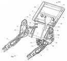
회전 동작이 멈춰진 상기 풋레스트 플레이트(23)는 도 7과 내지 도 9와 같이 후방시트를 향해 완전히 회전된 상태이며, 이때부터 뒷좌석 승객은 상기 풋레스트 플레이트(23)상에 발을 올려놓고 편안한 자세를 취하게 된다.7 and 9, the rear seat passenger puts his / her foot on the
그리고, 도 7의 상태와 같이 후방시트를 향해 회전하고 있던 풋레스트 플레이트(23)를 도 1의 상태와 같이 시트백(2)의 후방 하측에 세워진 상태로 보관하고자 할 때, 뒷좌석 승객은 중립위치에 있는 스위치(19)를 반대쪽 방향으로 조작한다.When the
그러면, 구동모터(17)로 인가되는 전류의 방향으로 바뀌어 이번에는 상기 구동모터(17)가 전술한 방향의 반대방향인 역방향 회전(반 시계방향 회전)을 하게 되고, 상기 구동모터(17)의 동력을 전달받는 리드스크루(33)는 반 시계방향 축회전을 하게 된다.In this case, the direction of the current applied to the
상기 리드스크루(33)가 반 시계방향 축회전을 하면 스토퍼너트(36)와 접촉하고 있던 리드스크루 너트(34)는 상기 리드스크루(33)를 따라 상기 구동모터(17)쪽으로 이동하게 되고, 동시에 리드스크루 브라켓(35)도 이동하게 된다.When the
상기 리드스크루 브라켓(35)이 이동하면 연결로드(32) 및 고정브라켓(31)을 매개로 연결된 풋레스트 플레이트(23)도 함께 이동하려고 하지만, 상기 풋레스트 플레이트(23)는 힌지파이프(21)와 결합되어 있는 상태이기 때문에 상기 리드스크루 브라켓(35)이 이동하는 방향으로 함께 이동하지 못하고, 대신에 상기 힌지파이프(21)를 중심으로 도 7의 상태에서 시계방향으로 회전을 하면서 시트백(2)의 후방 하측에 세워지는 동작을 하게 된다.When the
한편, 상기 리드스크루(33)를 따라 이동하던 상기 리드스크루 너트(34)가 상기 구동모터(17)쪽으로 완전히 이동을 하여 더 이상 이동하지 않으면, 도 7의 상태에서 시계방향으로 회전을 하던 상기 풋레스트 플레이트(23)도 회전동작이 멈춰지게 된다.On the other hand, if the
회전동작이 멈춰진 상기 풋레스트 플레이트(23)는 도 1과 같이 시트백(2)의 후방 하측에 세워져서 보관된 상태가 된다.The
상기와 같이 풋레스트 플레이트(23)의 회전 동작이 멈춰지면 사용자는 반대쪽 방향으로 조작하였던 스위치(19)를 다시 중립위치로 복귀시켜 상기 구동모터(17)로 인가되는 전원을 차단함으로써 상기 구동모터(17)의 동작을 종료시키게 된다.When the rotation of the
이상과 같이 본 발명에 따른 뒷좌석 승객용 풋레스트 장치는, 풋레스트 플레이트(23)가 후방시트를 향하여 회전하는 동작 및 시트백(2)의 후방 하측에 세워져서 보관되는 동작이 상기 시트백(2)에 설치된 스위치(19)의 간단한 조작으로 진행되는 구성이므로, 사용자의 편의성이 크게 향상되는 장점이 있다.As described above, the rear seat passenger's footrest device according to the present invention is configured such that the operation in which the
또한, 본 발명의 풋레스트 장치는 내구성이 높은 리드스크루(33)를 사용하는 구성이기 때문에 작동불량에 따른 고장의 염려가 없는 장점도 있다.In addition, since the footrest device of the present invention uses a high-
도 1 내지 도 3은 본 발명에 따른 뒷좌석 승객용 풋레스트 장치의 측면도와 사시도 및 평면도,1 to 3 are a side view, a perspective view and a plan view of a rear seat passenger footrest device according to the present invention,
도 4는 본 발명에 따른 뒷좌석 승객용 풋레스트 장치의 분해 사시도,4 is an exploded perspective view of a rear seat passenger footrest device according to the present invention,
도 5와 도 6은 본 발명에 따른 뒷좌석 승객용 풋레스트 장치에서 보강브라켓과 동력전달 조립체를 설명하기 위한 도면,5 and 6 are views for explaining a reinforcing bracket and a power transmission assembly in a rear seat passenger footrest device according to the present invention,
도 7 내지 도 9는 본 발명에 따른 뒷좌석 승객용 풋레스트 장치의 작동후 상태를 보여주기 위한 측면도와 사시도 및 저면 사시도이다.7 to 9 are a side view, a perspective view and a bottom perspective view for showing a state after operation of the rear seat passenger footrest device according to the present invention.
< 도면의 주요 부분에 대한 부호의 설명 >Description of the Related Art
2 - 시트백 3 - 시트쿠션프레임2 - Seatback 3 - Seat Cushion Frame
4 - 시트백프레임 11 - 고정파이프4 - Seatback frame 11 - Fixed pipe
13 - 베이스 플레이트 15 - 모터브라켓13 - Base plate 15 - Motor bracket
17 - 구동모터 19 - 스위치17 - drive motor 19 - switch
21 - 힌지파이프 23 - 풋레스트 플레이트21 - Hinge pipe 23 - Footrest plate
25 - 보강브라켓 30 - 동력전달 조립체25 - Reinforcing bracket 30 - Power transmission assembly
31 - 고정브라켓 32 - 연결로드31 - Fixing bracket 32 - Connection rod
33 - 리드스크루 34 - 리드스크루 너트33 - Lead Screw 34 - Lead Screw Nut
35 - 리드스크루 브라켓 36 - 스토퍼너트35 - Lead Screw Bracket 36 - Stopper Nut
Claims (6)
Translated fromKoreanPriority Applications (1)
| Application Number | Priority Date | Filing Date | Title |
|---|---|---|---|
| KR1020090067176AKR101568046B1 (en) | 2009-07-23 | 2009-07-23 | Footrest device for rear passengers |
Applications Claiming Priority (1)
| Application Number | Priority Date | Filing Date | Title |
|---|---|---|---|
| KR1020090067176AKR101568046B1 (en) | 2009-07-23 | 2009-07-23 | Footrest device for rear passengers |
Publications (2)
| Publication Number | Publication Date |
|---|---|
| KR20110009796A KR20110009796A (en) | 2011-01-31 |
| KR101568046B1true KR101568046B1 (en) | 2015-11-10 |
Family
ID=43615359
Family Applications (1)
| Application Number | Title | Priority Date | Filing Date |
|---|---|---|---|
| KR1020090067176AExpired - Fee RelatedKR101568046B1 (en) | 2009-07-23 | 2009-07-23 | Footrest device for rear passengers |
Country Status (1)
| Country | Link |
|---|---|
| KR (1) | KR101568046B1 (en) |
Families Citing this family (6)
| Publication number | Priority date | Publication date | Assignee | Title |
|---|---|---|---|---|
| CN103802709A (en)* | 2012-11-07 | 2014-05-21 | 信昌机械厂股份有限公司 | Automatic foot back cushion device |
| CN106218472A (en)* | 2016-08-25 | 2016-12-14 | 成都市天龙交通设备有限公司 | Foot leans on switching mechanism and assembly method |
| CN111923803A (en)* | 2020-08-14 | 2020-11-13 | 重庆宏立至信科技发展集团股份有限公司 | Seat framework with electric pedal |
| CN113928454B (en)* | 2021-11-29 | 2024-07-02 | 尹向阳 | Pedal device capable of automatically ejecting and recovering |
| CN116811700A (en)* | 2023-04-14 | 2023-09-29 | 延锋国际座椅系统有限公司 | Pedal mechanism with collapse protection member |
| CN116945995A (en)* | 2023-07-19 | 2023-10-27 | 继峰座椅(合肥)有限公司 | A car seat with a pressure-sensitive foot pedal and a method for unfolding and retracting the foot pedal |
Citations (1)
| Publication number | Priority date | Publication date | Assignee | Title |
|---|---|---|---|---|
| JP2006036136A (en)* | 2004-07-29 | 2006-02-09 | Johnson Controls Technol Co | Vehicular ottoman device |
- 2009
- 2009-07-23KRKR1020090067176Apatent/KR101568046B1/ennot_activeExpired - Fee Related
Patent Citations (1)
| Publication number | Priority date | Publication date | Assignee | Title |
|---|---|---|---|---|
| JP2006036136A (en)* | 2004-07-29 | 2006-02-09 | Johnson Controls Technol Co | Vehicular ottoman device |
Also Published As
| Publication number | Publication date |
|---|---|
| KR20110009796A (en) | 2011-01-31 |
Similar Documents
| Publication | Publication Date | Title |
|---|---|---|
| KR101568046B1 (en) | Footrest device for rear passengers | |
| US9102246B2 (en) | Cable synchronizer system | |
| US9511694B2 (en) | Motor vehicle seat having an armrest | |
| US7494173B2 (en) | Retractable vehicle seat of laterally folding type | |
| CN106467039A (en) | Vehicle seat used and vehicle | |
| CN107444203B (en) | Seat adjusting device and vehicle seat | |
| KR101864253B1 (en) | Walk-in and folding apparatus of vehicle seat | |
| CN111660889B (en) | Vehicle seat | |
| JP2022061570A (en) | Table for seats | |
| KR20110009797A (en) | Rear passenger footrest device | |
| JP6809161B2 (en) | Vehicle seat | |
| JP2019077240A (en) | Seat back for chair and vehicle seat | |
| KR101047613B1 (en) | Electric footrest device | |
| JP2007253763A (en) | Ottoman structure of seat for vehicle | |
| JP5073320B2 (en) | Vehicle seat slide device | |
| JP5130760B2 (en) | Vehicle seat device | |
| KR101138734B1 (en) | Foot rest apparatus | |
| KR20090112430A (en) | Headrest folding structure of vehicle seat | |
| JP6234949B2 (en) | Vehicle seat table equipment | |
| KR101168714B1 (en) | Apparatus for forward and backward movement of car headrests | |
| JP2008273399A (en) | Cargo board interlocking structure | |
| JP6582508B2 (en) | Vehicle seat | |
| JP2021062843A (en) | Headrest housing device | |
| JP2006239269A (en) | Ottoman device for vehicle seat | |
| JP3452804B2 (en) | Car seat equipment |
Legal Events
| Date | Code | Title | Description |
|---|---|---|---|
| PA0109 | Patent application | St.27 status event code:A-0-1-A10-A12-nap-PA0109 | |
| PN2301 | Change of applicant | St.27 status event code:A-3-3-R10-R11-asn-PN2301 St.27 status event code:A-3-3-R10-R13-asn-PN2301 | |
| PG1501 | Laying open of application | St.27 status event code:A-1-1-Q10-Q12-nap-PG1501 | |
| PN2301 | Change of applicant | St.27 status event code:A-3-3-R10-R11-asn-PN2301 St.27 status event code:A-3-3-R10-R13-asn-PN2301 | |
| R18-X000 | Changes to party contact information recorded | St.27 status event code:A-3-3-R10-R18-oth-X000 | |
| A201 | Request for examination | ||
| PA0201 | Request for examination | St.27 status event code:A-1-2-D10-D11-exm-PA0201 | |
| D13-X000 | Search requested | St.27 status event code:A-1-2-D10-D13-srh-X000 | |
| D14-X000 | Search report completed | St.27 status event code:A-1-2-D10-D14-srh-X000 | |
| E902 | Notification of reason for refusal | ||
| PE0902 | Notice of grounds for rejection | St.27 status event code:A-1-2-D10-D21-exm-PE0902 | |
| E13-X000 | Pre-grant limitation requested | St.27 status event code:A-2-3-E10-E13-lim-X000 | |
| P11-X000 | Amendment of application requested | St.27 status event code:A-2-2-P10-P11-nap-X000 | |
| P13-X000 | Application amended | St.27 status event code:A-2-2-P10-P13-nap-X000 | |
| E701 | Decision to grant or registration of patent right | ||
| PE0701 | Decision of registration | St.27 status event code:A-1-2-D10-D22-exm-PE0701 | |
| GRNT | Written decision to grant | ||
| PR0701 | Registration of establishment | St.27 status event code:A-2-4-F10-F11-exm-PR0701 | |
| PR1002 | Payment of registration fee | Fee payment year number:1 St.27 status event code:A-2-2-U10-U11-oth-PR1002 | |
| PG1601 | Publication of registration | St.27 status event code:A-4-4-Q10-Q13-nap-PG1601 | |
| R18-X000 | Changes to party contact information recorded | St.27 status event code:A-5-5-R10-R18-oth-X000 | |
| PN2301 | Change of applicant | St.27 status event code:A-5-5-R10-R11-asn-PN2301 St.27 status event code:A-5-5-R10-R13-asn-PN2301 | |
| P22-X000 | Classification modified | St.27 status event code:A-4-4-P10-P22-nap-X000 | |
| PR1001 | Payment of annual fee | Fee payment year number:4 St.27 status event code:A-4-4-U10-U11-oth-PR1001 | |
| PN2301 | Change of applicant | St.27 status event code:A-5-5-R10-R11-asn-PN2301 St.27 status event code:A-5-5-R10-R13-asn-PN2301 | |
| PN2301 | Change of applicant | St.27 status event code:A-5-5-R10-R11-asn-PN2301 St.27 status event code:A-5-5-R10-R13-asn-PN2301 | |
| PR1001 | Payment of annual fee | Fee payment year number:5 St.27 status event code:A-4-4-U10-U11-oth-PR1001 | |
| PR1001 | Payment of annual fee | Fee payment year number:6 St.27 status event code:A-4-4-U10-U11-oth-PR1001 | |
| R18-X000 | Changes to party contact information recorded | St.27 status event code:A-5-5-R10-R18-oth-X000 | |
| R18-X000 | Changes to party contact information recorded | St.27 status event code:A-5-5-R10-R18-oth-X000 | |
| PR1001 | Payment of annual fee | Fee payment year number:7 St.27 status event code:A-4-4-U10-U11-oth-PR1001 | |
| PC1903 | Unpaid annual fee | Not in force date:20221105 Payment event data comment text:Termination Category : DEFAULT_OF_REGISTRATION_FEE St.27 status event code:A-4-4-U10-U13-oth-PC1903 | |
| PC1903 | Unpaid annual fee | Ip right cessation event data comment text:Termination Category : DEFAULT_OF_REGISTRATION_FEE Not in force date:20221105 St.27 status event code:N-4-6-H10-H13-oth-PC1903 | |
| P22-X000 | Classification modified | St.27 status event code:A-4-4-P10-P22-nap-X000 | |
| PN2301 | Change of applicant | St.27 status event code:A-5-5-R10-R11-asn-PN2301 St.27 status event code:A-5-5-R10-R13-asn-PN2301 |