KR101566312B1 - Vacuum cleaner equipped with vibration suppression device - Google Patents
Vacuum cleaner equipped with vibration suppression deviceDownload PDFInfo
- Publication number
- KR101566312B1 KR101566312B1KR1020090040805AKR20090040805AKR101566312B1KR 101566312 B1KR101566312 B1KR 101566312B1KR 1020090040805 AKR1020090040805 AKR 1020090040805AKR 20090040805 AKR20090040805 AKR 20090040805AKR 101566312 B1KR101566312 B1KR 101566312B1
- Authority
- KR
- South Korea
- Prior art keywords
- dust
- filter
- dust collecting
- collecting unit
- rotary knob
- Prior art date
- Legal status (The legal status is an assumption and is not a legal conclusion. Google has not performed a legal analysis and makes no representation as to the accuracy of the status listed.)
- Expired - Fee Related
Links
Images


Classifications
- A—HUMAN NECESSITIES
- A47—FURNITURE; DOMESTIC ARTICLES OR APPLIANCES; COFFEE MILLS; SPICE MILLS; SUCTION CLEANERS IN GENERAL
- A47L—DOMESTIC WASHING OR CLEANING; SUCTION CLEANERS IN GENERAL
- A47L9/00—Details or accessories of suction cleaners, e.g. mechanical means for controlling the suction or for effecting pulsating action; Storing devices specially adapted to suction cleaners or parts thereof; Carrying-vehicles specially adapted for suction cleaners
- A47L9/20—Means for cleaning filters
- A—HUMAN NECESSITIES
- A47—FURNITURE; DOMESTIC ARTICLES OR APPLIANCES; COFFEE MILLS; SPICE MILLS; SUCTION CLEANERS IN GENERAL
- A47L—DOMESTIC WASHING OR CLEANING; SUCTION CLEANERS IN GENERAL
- A47L5/00—Structural features of suction cleaners
- A47L5/12—Structural features of suction cleaners with power-driven air-pumps or air-compressors, e.g. driven by motor vehicle engine vacuum
- A47L5/22—Structural features of suction cleaners with power-driven air-pumps or air-compressors, e.g. driven by motor vehicle engine vacuum with rotary fans
- A47L5/36—Suction cleaners with hose between nozzle and casing; Suction cleaners for fixing on staircases; Suction cleaners for carrying on the back
- A47L5/362—Suction cleaners with hose between nozzle and casing; Suction cleaners for fixing on staircases; Suction cleaners for carrying on the back of the horizontal type, e.g. canister or sledge type
- A—HUMAN NECESSITIES
- A47—FURNITURE; DOMESTIC ARTICLES OR APPLIANCES; COFFEE MILLS; SPICE MILLS; SUCTION CLEANERS IN GENERAL
- A47L—DOMESTIC WASHING OR CLEANING; SUCTION CLEANERS IN GENERAL
- A47L9/00—Details or accessories of suction cleaners, e.g. mechanical means for controlling the suction or for effecting pulsating action; Storing devices specially adapted to suction cleaners or parts thereof; Carrying-vehicles specially adapted for suction cleaners
- A47L9/10—Filters; Dust separators; Dust removal; Automatic exchange of filters
- A47L9/12—Dry filters
- A—HUMAN NECESSITIES
- A47—FURNITURE; DOMESTIC ARTICLES OR APPLIANCES; COFFEE MILLS; SPICE MILLS; SUCTION CLEANERS IN GENERAL
- A47L—DOMESTIC WASHING OR CLEANING; SUCTION CLEANERS IN GENERAL
- A47L9/00—Details or accessories of suction cleaners, e.g. mechanical means for controlling the suction or for effecting pulsating action; Storing devices specially adapted to suction cleaners or parts thereof; Carrying-vehicles specially adapted for suction cleaners
- A47L9/10—Filters; Dust separators; Dust removal; Automatic exchange of filters
- A47L9/16—Arrangement or disposition of cyclones or other devices with centrifugal action
- B—PERFORMING OPERATIONS; TRANSPORTING
- B01—PHYSICAL OR CHEMICAL PROCESSES OR APPARATUS IN GENERAL
- B01D—SEPARATION
- B01D45/00—Separating dispersed particles from gases or vapours by gravity, inertia, or centrifugal forces
- B01D45/12—Separating dispersed particles from gases or vapours by gravity, inertia, or centrifugal forces by centrifugal forces
- B01D45/14—Separating dispersed particles from gases or vapours by gravity, inertia, or centrifugal forces by centrifugal forces generated by rotating vanes, discs, drums or brushes
- B—PERFORMING OPERATIONS; TRANSPORTING
- B01—PHYSICAL OR CHEMICAL PROCESSES OR APPARATUS IN GENERAL
- B01D—SEPARATION
- B01D46/00—Filters or filtering processes specially modified for separating dispersed particles from gases or vapours
- B01D46/24—Particle separators, e.g. dust precipitators, using rigid hollow filter bodies
- B01D46/2403—Particle separators, e.g. dust precipitators, using rigid hollow filter bodies characterised by the physical shape or structure of the filtering element
- B01D46/2411—Filter cartridges
- B—PERFORMING OPERATIONS; TRANSPORTING
- B01—PHYSICAL OR CHEMICAL PROCESSES OR APPARATUS IN GENERAL
- B01D—SEPARATION
- B01D50/00—Combinations of methods or devices for separating particles from gases or vapours
- B01D50/20—Combinations of devices covered by groups B01D45/00 and B01D46/00
- B—PERFORMING OPERATIONS; TRANSPORTING
- B01—PHYSICAL OR CHEMICAL PROCESSES OR APPARATUS IN GENERAL
- B01D—SEPARATION
- B01D2279/00—Filters adapted for separating dispersed particles from gases or vapours specially modified for specific uses
- B01D2279/55—Filters adapted for separating dispersed particles from gases or vapours specially modified for specific uses for cleaning appliances, e.g. suction cleaners
Landscapes
- Engineering & Computer Science (AREA)
- Mechanical Engineering (AREA)
- Chemical & Material Sciences (AREA)
- Chemical Kinetics & Catalysis (AREA)
- Physics & Mathematics (AREA)
- Geometry (AREA)
- Filters For Electric Vacuum Cleaners (AREA)
Abstract
Translated fromKoreanDescription
Translated fromKorean본 발명은 가정용, 산업용, 업소용 청소기 등의 청소기기에 관한 것으로서, 더욱 상세하게는 집진유닛의 내부에 장착되는 필터에 포집된 먼지를 필터를 분리하지 않고 제거할 수 있도록 하는 진공청소기에 관한 것이다.BACKGROUND OF THE INVENTION 1. Field of the Invention [0001] The present invention relates to a cleaning device for a household, an industrial, or a business vacuum cleaner. More particularly, the present invention relates to a vacuum cleaner that removes dust collected in a filter installed in a dust-
일반적으로, 진공청소기에는 먼지를 포집하여 분리하는 필터가 장착된다. 이러한 필터는 원심분리부 또는 먼지봉투에 의해 분리되지 않은 미세 먼지를 포집하는 것에 의해 청소효율을 향상시키고 사용자의 위생 안전성을 향상시킨다.Generally, a vacuum cleaner is equipped with a filter for collecting and separating dust. These filters collect fine dust that has not been separated by a centrifugal separator or a dust bag, thereby improving the cleaning efficiency and improving the sanitary safety of the user.
그러나 진공청소기를 장시간 사용하는 경우 필터에는 과다한 먼지가 포집되어 배기 성능이 저하된다. 필터의 배기 성능 저하는 청소효율의 저하, 진공청소기의 과부하 발생, 사용자의 위생 저해 등의 문제를 발생시킨다.However, when the vacuum cleaner is used for a long time, excessive dust is collected in the filter, and the exhaust performance is deteriorated. The deterioration of the exhaust performance of the filter causes problems such as deterioration of the cleaning efficiency, overload of the vacuum cleaner, inhibition of the user's sanitation.
따라서 진공청소기의 최상의 성능을 유지하기 위해서 사용자는 주기적으로 필터를 진공청소기로부터 분리하여 청소하여 주어야만 하는 사용상의 불편함을 겪 게 된다.Therefore, in order to maintain the best performance of the vacuum cleaner, the user must periodically remove the filter from the vacuum cleaner and experience the inconvenience of using the vacuum cleaner.
이에 따라 진공청소기에 장착된 필터를 분리하지 않고 필터에 포집된 먼지를 제거할 수 있도록 하는 다양한 종래기술이 개시되었다.Accordingly, various prior arts have been disclosed to enable the dust collected in the filter to be removed without removing the filter mounted on the vacuum cleaner.
이러한 종래기술로는 대한민국 공개특허공보 제 2009-16498 호(종래기술 1), 대한민국 공개특허공보 제 2008-104516 호(종래기술 2), 일본 공개특허공보 제 2007-125294 호(종래기술 3) 및 일본 공개특허공보 제 2000-342492 호(종래기술 4) 등에 개시된 기술을 들 수 있다.Such prior arts are disclosed in Korean Patent Laid-Open Publication No. 2009-16498 (Prior Art 1), Korean Patent Laid-Open Publication No. 2008-104516 (Prior Art 2), Japanese Laid-Open Patent Publication No. 2007-125294 (Prior Art 3) Japanese Unexamined Patent Application Publication No. 2000-342492 (Prior Art 4), and the like.
상기 종래기술 1은 중앙이 관통되는 필터의 중앙 영역에 디플렉터들을 배치한 후 모터를 이용하여 디플렉터들을 회전시킴으로써 필터에 포집된 먼지를 제거하는 것을 개시한다.The prior art 1 discloses disposing deflectors in a central region of a filter through which a center passes, and then rotating the deflectors using a motor to remove dust collected in the filter.
상기 종래기술 2는 진공청소기의 내부 공기 흐름에 의해 회전되는 털기구동부를 이용해 필터털기부를 회전시켜 필터에 포집된 먼지를 제거하는 것을 개시한다.The prior art 2 discloses a method for removing dust collected in a filter by rotating a filter whisk using a whisk drive unit rotated by an internal air flow of a vacuum cleaner.
상기 종래기술 3은 조작부를 이용해 클리닝부재를 회전시킴으로써 플리츠필터에 포집된 먼지를 제거하는 것을 개시한다.The above-mentioned prior art 3 discloses to remove the dust collected in the pleated filter by rotating the cleaning member using the operating part.
상기 종래기술 4는 외부에 구비된 핸들을 회전시켜 플리츠 필터 선단부의 돌기가 튕겨져 먼지를 제거하는 것을 개시한다.In the prior art 4, the handle provided on the outside is rotated to protrude the protrusion of the pleat filter to remove dust.
상술한 종래기술들을 살펴보면, 종래기술 1은 디플렉터와 모터를 구비하게 되므로, 구조가 복잡해지고, 부품 수가 증가하여 진공청소기의 크기를 크게 하고, 진공청소기의 무게를 증가시킨다.According to the related art, since the conventional art 1 includes a deflector and a motor, the structure is complicated and the number of components increases, thereby increasing the size of the vacuum cleaner and increasing the weight of the vacuum cleaner.
또한, 종래기술 1은 먼지통이 분리된 상태에서는 수동으로 디렉터를 회전시킬 수 없게 되므로, 필터를 먼지통으로부터 분리함이 없이 필터에 포집된 먼지를 제거할 수 없게 된다.In addition, in the prior art 1, since the director can not be rotated manually in the state that the dust bin is separated, the dust collected on the filter can not be removed without separating the filter from the dust bin.
상술한 종래기술 2는 진공청소기의 내부 공기 흐름을 이용하게 되므로 필터에 포집된 먼지를 제거하기에 적당한 회전력이 발생하지 않아 필터에 포집된 먼지의 제거 효율이 저하된다.The conventional art 2 uses the internal air flow of the vacuum cleaner, so that a suitable rotational force for removing the dust collected on the filter is not generated, and the efficiency of removing the dust collected on the filter is lowered.
상술한 종래기술 3은 집진장치가 진공청소기에 장착된 상태에서는 클리닝부재를 회전시킬 수 없게 되므로, 진공청소기의 구동 중에는 필터에 포집된 먼지를 제거할 수 없게 된다.In the above-described prior art 3, since the cleaning member can not be rotated in a state where the dust collecting apparatus is mounted on the vacuum cleaner, dust collected on the filter can not be removed during driving of the vacuum cleaner.
상술한 종래기술 4는 돌기의 진동이 필터에 포집된 먼지를 필터로부터 분리시킬 수 있는 힘이 작기 때문에 필터에 포집된 먼지의 제거 효율이 저하된다.In the above-described prior art 4, since the force of separating the dust collected in the filter from the filter is small, the dust removal efficiency of the filter is lowered.
따라서 상술한 종래기술의 문제점을 해결하기 위한 본 발명은, 집진유닛이 진공청소기에 장착된 상태나 분리된 상태와 무관하게 집진유닛에 장착된 필터에 포집된 먼지를 제거할 수 있도록 하는 진공청소기를 제공하는 것을 목적으로 한다.SUMMARY OF THE INVENTION Accordingly, the present invention has been made keeping in mind the above problems occurring in the prior art, and an object of the present invention is to provide a vacuum cleaner for removing dust collected on a filter mounted on a dust collecting unit regardless of whether the dust collecting unit is mounted on a vacuum cleaner, The purpose is to provide.
또한, 본 발명은 진공청소기의 구동 상태에서도 집진유닛에 장착된 필터에 포집된 먼지를 제거할 수 있도록 하는 진공청소기를 제공하는 것을 다른 목적으로 한다.Another object of the present invention is to provide a vacuum cleaner capable of removing dust collected in a filter mounted on a dust collecting unit even when the vacuum cleaner is in operation.
또한, 본 발명은 소형화 경량화를 달성하면서 필터에 포집된 먼지를 용이하게 제거할 수 있도록 하는 진공청소기를 제공하는 것을 또 다른 목적으로 한다.It is still another object of the present invention to provide a vacuum cleaner that can easily remove dust collected on a filter while attaining miniaturization and weight reduction.
상술한 목적을 달성하기 위한 본 발명의 진공청소기는, 집진유닛; 상기 집진유닛의 내부에 장착되는 필터; 상기 필터를 털어주는 제진장치; 및, 상기 제진장치를 회전시키며, 상기 집진유닛의 외부면에 구비된 회전손잡이;를 포함하며, 상기 집진유닛은 상기 회전손잡이가 외부로 노출되도록 진공청소기의 본체에 장착되는 것을 특징으로 한다.According to an aspect of the present invention, there is provided a vacuum cleaner including: a dust collecting unit; A filter mounted inside the dust collecting unit; A vibration isolation device for shaking the filter; And a rotary knob provided on an outer surface of the dust collecting unit for rotating the vibration elimination device. The dust collecting unit is mounted on the body of the vacuum cleaner so that the rotary knob is exposed to the outside.
이를 위해 상기 본체는 상기 회전손잡이가 외부로 노출되는 회전손잡이 노출공이 형성된 본체커버를 더 포함하여 구성될 수 있다.To this end, the main body may further include a main cover having a rotary knob exposure hole through which the rotary knob is exposed to the outside.
상기 집진유닛은 상기 본체에 장착된 상태 또는 상기 본체로부터 분리된 상 태에서 상기 회전손잡이에 의해 상기 제진장치를 회전시킬 수 있도록 구성된다.The dust collecting unit is configured to be able to rotate the vibration damping device by the rotary knob in a state in which the dust collecting unit is mounted on the main body or separated from the main body.
또한, 상기 집진유닛은, 상기 진공청소기의 구동 중에 상기 회전손잡이에 의해 상기 제진장치를 회전시킬 수 있도록 구성된다.Further, the dust collecting unit is configured to be able to rotate the vibration damping device by the rotary knob while the vacuum cleaner is being driven.
또한, 상기 집진유닛은 상기 1차 먼지수집영역과 상기 2차 먼지수집영역에 수집된 먼지를 동시에 배출할 수 있도록 상기 집진유닛의 저부에 개폐 가능하게 결합되며 먼지통배기구가 형성된 먼지배출커버를 더 포함하여 구성될 수 있다.The dust collecting unit further includes a dust discharging cover coupled to the bottom of the dust collecting unit so that dust collected in the primary dust collecting area and the secondary dust collecting area can be discharged at the same time, .
또한, 상기 집진유닛은 상기 회전손잡이가 상기 집진유닛의 상부에 형성되고, 상기 집진유닛의 공기를 배출하는 먼지통배기구는 상기 집진유닛의 하부에 형성되도록 구성되어, 상기 집진유닛으로 유입되는 공기의 유로를 진공청소기의 본체에 형성하는 것을 가능하게 한다. 이에 따라, 상기 집진유닛 및 진공청소기를 소형화 및 경량화시킬 수 있다.In the dust collecting unit, the rotary knob is formed on the upper portion of the dust collecting unit, and a dust box exhaust port for discharging the air of the dust collecting unit is formed in a lower portion of the dust collecting unit, In the main body of the vacuum cleaner. Accordingly, the dust collecting unit and the vacuum cleaner can be made smaller and lighter.
또한, 상기 집진유닛은 상기 집진유닛의 내부 영역을 원심분리부에서 분리된 먼지를 수집하는 1차 먼지수집영역과 상기 필터에서 제거된 먼지를 수집하는 2차 먼지수집영역으로 분할하며 상기 필터가 내장되는 원심분리부;를 포함하여 구성될 수 있다.The dust collecting unit divides an internal area of the dust collecting unit into a primary dust collecting area for collecting dust separated from the centrifugal separating part and a secondary dust collecting area for collecting dust removed from the filter, And a centrifugal separator.
상기 원심분리부는, 필터; 상기 필터의 상부를 지지하며 제 2 축공이 형성된 상부필터커버; 상기 필터의 하부를 지지하며 하부에는 필터배기관이 형성된 하부필터커버; 및, 상기 하부필터커버의 저면을 지지하도록 내주면에 일정 간격을 가지고 돌출 형성되는 적어도 하나의 필터지지턱을 구비하고, 상기 먼지통에 장착되는 경우 상기 1차 먼지수집영역과 2차 먼지수집영역을 분리하는 사이클론;을 포함하여 구성될 수 있다.The centrifugal separator includes a filter; An upper filter cover supporting an upper portion of the filter and having a second shaft hole; A lower filter cover which supports a lower portion of the filter and has a filter exhaust pipe at a lower portion thereof; And at least one filter support jaw protruding from the inner circumferential surface to support the bottom surface of the lower filter cover at a predetermined interval, wherein when the dust collecting container is mounted on the dust container, the primary dust collection area and the secondary dust collection area are separated The cyclone may be configured to include:
본 발명은 집진유닛으로부터 필터를 분리하지 않은 상태에서 필터에 포집된 먼지를 제거할 수 있도록 함으로써, 집진유닛이 진공청소기에 장착된 상태 또는 분리된 상태와 관계없이 집진유닛에 내장되는 필터에 포집된 먼지를 용이하게 제거할 수 있도록 한다.The present invention can remove the dust collected in the filter without separating the filter from the dust collecting unit. Thus, regardless of whether the dust collecting unit is mounted on the vacuum cleaner or is separated, So that dust can be easily removed.
본 발명은 또한 진공청소기에 장착되는 필터의 먼지를 제거하기 위한 별도의 구동 수단을 구비하지 않아도 되므로 필터에 포집된 먼지 제거 기능을 가지는 집진유닛과 진공청소기의 경량화 및 소형화를 달성할 수 있도록 한다.The present invention also eliminates the need for a separate driving means for removing the dust of the filter mounted on the vacuum cleaner. Thus, weight saving and miniaturization of the dust collecting unit and the vacuum cleaner, which are collected in the filter, can be achieved.
이하, 본 발명의 실시 예를 나타내는 첨부 도면을 참조하여 본 발명을 더욱 상세히 설명한다.Hereinafter, the present invention will be described in more detail with reference to the accompanying drawings showing embodiments of the present invention.
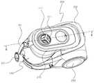
도 1은 본 발명의 실시 예에 따르는 진공청소기(1)의 사시도이고, 도 2는 도 1의 진공청소기(1)의 본체커버(210)가 열린 상태의 사시도이며, 도 3은 진공청소기(1)로부터 분리된 집진유닛(100)의 사시도이고, 도 4는 도 3의 집진유닛(100)의 분해 사시도이다.FIG. 1 is a perspective view of a vacuum cleaner 1 according to an embodiment of the present invention. FIG. 2 is a perspective view of the vacuum cleaner 1 of FIG. FIG. 4 is an exploded perspective view of the dust collecting
도 1 내지 도 4와 같이 진공청소기(1)는 집진유닛(100)과 본체(200)로 구성된다. 1 to 4, the vacuum cleaner 1 includes a
상기 본체(200)는 노즐결합공(201), 회전손잡이 노출공(211)이 형성된 본체커버(210), 본체 손잡이(202) 및 진공청소기(1)의 이동을 위한 바퀴(203)를 포함하여 구성된다.The
상기 노즐결합공(201)은 본체(200)의 하부에 형성되어 노즐의 호스(도면에 미 도시)가 결합되도록 구성된다.The
상기 본체커버(210)는 회전손잡이부(110)와 대향하는 위치에 회전손잡이(111)가 외부로 노출되는 회전손잡이 노출공(211)이 형성되고, 일측 단부는 본체(200)에 회전 가능하게 고정된다.The
상기 본체(200)는 진공청소기(1)의 흡입력을 발생시키는 팬모터유닛(도면에 미 도시) 등을 포함하며 이는 종래기술에서 공지된 것이므로 그 도시 및 상세한 설명은 생략한다.The
도 4와 같이 상기 집진유닛(100)은 회전손잡이부(110), 먼지통커버(120), 먼지통(180), 원심분리부(300), 제진장치(400)를 포함하여 구성된다.4, the
상기 회전손잡이부(110)는 회전손잡이(111)와 회전손잡이축(112)으로 구성된다. 상기 회전손잡이(111)는 사용자가 용이하게 파지 가능하며 회전손잡이축(112)으로 큰 회전력을 발생시킬 수 있도록 가능한 한 큰 직경을 가지도록 형성되는 것이 바람직하다. 상기 회전손잡이축(112)은 하단부가 집진유닛(100)에 장착되는 제진장치(400)와 결합된다.The
상기 먼지통커버(120)는 회전손잡이축(112)이 관통하는 제 1 축공(121)과, 노즐결합공(201)을 통해 유입된 외부 공기를 먼지통(180)의 내부로 유입시키는 유입구(101)를 가진다. 상기 제 1 축공(121)은 먼지통커버(120)의 중앙면을 관통 형성되며, 회전손잡이축(112)이 회전 가능하면서 회전손잡이축(112)과 긴밀히 결합하는 내경을 가지도록 형성된다. 이에 따라 회전 가능하게 결합되는 회전손잡이축(112)과 제 1 축공(121)의 사이에서 공기의 누설이 방지된다.The
상기 유입구(101)는 형성 위치가 제한되는 것은 아니며, 본체(200)에 외부 공기를 집진유닛(100)으로 유입시키도록 형성되는 위치에 따라 먼지통(180) 등 다양한 위치에 형성될 수 있다.The
상기 먼지통(180)은 먼지통 손잡이(181)와 먼지배출커버(182)를 포함하여 구성된다.The
상기 먼지통 손잡이(181)는 먼지통(180)의 일 측면에서 파지가 용이하도록 형성된다.The
상기 먼지배출커버(182)는 유입구(101)를 통해 유입되어 먼지가 분리된 공기가 배출되는 먼지통배기구(183)가 형성된다. 이러한 구조의 먼지배출커버(182)는 중앙이 먼지통배기구(183)를 형성하도록 관통되어 먼지통(180)의 저면에 개폐 가능하게 결합된다.The dust-discharging
상술한 바와 같이 먼지통배기구(183)를 집진유닛(100)의 하부에 결합되는 먼 지배출커버(182)에 형성함으로써, 집진유닛(100)으로 유입되는 공기를 위한 유로를 본체(200)에 구성할 수 있다. 이에 따라, 집진유닛(100) 및 진공청소기(1)를 소형화 및 경량화시킬 수 있다.The
상기 원심분리부(300)는 필터상부커버(310), 필터(320), 필터하부커버(330), 사이클론(340)을 포함하여 구성된다.The
상기 필터(320)는 플리츠필터(pleated filter) 등과 같이 중앙에 필터중공부(320a)를 가지는 원통형으로 형성된다.The
상기 필터상부커버(310)는 중앙에 제 2 축공(311)을 가지며 사이클론(340)의 내부에 장착된 필터(320)의 상부면과 결합된다. 이때 상기 제 2 축공(311)은 회전손잡이축(112)이 관통하여 결합됨으로써 회전손잡이축(112)의 하단부가 제진축(411)과 축결합될 수 있도록 한다.The
상기 필터하부커버(330)는 저면에 필터배기구(331)와 필터배기구(331)와 연통되는 필터배기관(332)을 포함하여 구성되어, 원심분리부(300) 내부에서 필터(320)의 저면을 지지한다.The filter
상기 사이클론(340)은 상부는 그릴공(341a)이 형성된 그릴(341)로 되고, 하부는 고정관(343)으로 되며, 내주 면의 하부에는 일정 간격을 이루는 다수의 필터하부커버 지지턱(344)이 돌출 형성되며, 외 주연에는 스커트(342)가 결합되는 원통형 관으로 구성된다.The upper part of the
상기 제진장치(400)는 제진축(411)과 제진축(411)에 결합되는 다수의 제진판(412)으로 구성된다. 상기 제진축(411)은 상부에서 회전손잡이축(112)과 축 결합되도록 구성된다. 이때 필터상부커버(310)를 사이에 두고 회전손잡이축(112)과 제진축(411)이 용이하게 결합될 수 있도록 제진축 상단부(411a)는 제진축(411)과 분리 가능하게 구성될 수 있다.The
상기 제진판(412)들은 제진축(411)의 외주면에서 방사상으로 다수가 결합된다. 상기 제진축(411)에 결합되는 제진판(412)들은 필터중공부(320a)에 결합되는 경우 필터중공부(320a)의 내주면으로 측부단부(413)가 일정 깊이 삽입되는 폭을 가지도록 형성된다. 이때 상기 제진판(412)들은 필터(320)의 파손을 방지하며, 필터(320)에 더 큰 먼지 제거를 위한 충격을 가할 수 있도록 탄성부재로 형성되는 것이 바람직하다.The
상술한 제진장치(400)의 구성에서 상기 제진판(412)은 제진축(411)에 나선형으로 결합되는 나선형 판 부재 등으로 다양하게 변형 실시될 수 있다.In the structure of the above-described
도 5는 도 1의 Ⅴ-Ⅴ 선을 따라 절단한 진공청소기(1)의 부분 단면도이다.5 is a partial sectional view of the vacuum cleaner 1 cut along the line V-V in FIG.
이하, 도 4 및 도 5를 참조하여 집진유닛(100)의 결합 구조를 설명한다.Hereinafter, the coupling structure of the
상기 사이클론(340)은 도 5와 같이 먼지통(180)의 내부에 결합된다. 먼지통(180)의 내부에 결합된 사이클론(340)은 먼지통(180)의 내부 영역을 1차 먼지수집영역(180a)과 2차 먼지수집영역(180b)으로 분리한다. 상기 1차 먼지수집영역(180a)은 사이클론(340)의 외부에서 분리되는 크고 무거운 먼지를 수집한다. 상 기 2차 먼지수집영역(180b)은 필터(320)에서 제진장치(400)에 의해 분리된 먼지를 수집한다.The
상기 필터하부커버(330)는 사이클론(340)의 내부로 삽입된 후 필터하부커버 지지턱(344)에 의해 지지 고정된다. 이때 필터하부커버 지지턱(344)의 사이에 위치되는 사이클론(340)의 내부 벽이 필터하부커버(330)와 일정 간격 이격되어 필터(320)에서 분리된 먼지가 2차 먼지수집영역(180b)으로 이동하는 공간(도면에 미 도시)을 형성한다.The filter
상기 필터(320)는 필터하부커버(330)가 필터하부커버 지지턱(344)에 고정된 상태에서 사이클론(340)의 내부에 삽입되어 필터하부커버(330)에 의해 지지 고정된다. 필터하부커버(330)가 사이클론(340)의 내부에 결합되면 필터중공부(320a)와 필터배기구(331)가 서로 연통되며, 필터배기구(331)는 필터배기관(332)에 의해 먼지통배기구(183)와 연통된다. 이 경우 먼지통배기구(183) 또는 필터배기관(332)에는 결합부 사이에서 공기의 누설이 발생하지 않도록 밀봉부재(도면에 미도시)가 결합된다.The
상기 회전손잡이부(110)는 회전손잡이축(112)이 제 1 축공(121)과 제 2 축공(311)을 통해 먼지통커버(120)와 필터상부커버(310)를 관통하여 제진축(411)과 축 결합된다. 이에 의해 사용자가 회전손잡이부(110)를 이용하여 제진장치(400)를 회전시킬 수 있게 된다.The
상기 제진장치(400)와 회전손잡이축(112)이 축결합 된 상태에서 먼지통커 버(120)를 먼지통(180)에 결합시키면 제진판(412)의 측부단부(413)가 필터중공부(320a)를 이루는 필터(320)의 내부로 일정 깊이 삽입되도록 제진판(412)과 필터(320)가 결합한다.When the
상기 먼지배출커버(182)는 먼지통(180)의 저부에 결합된 상태를 유지한다.The dust-discharging
이러한 결합에 의해 도 3과 같이 집진유닛(100)이 일체형으로 조립된다.By such a coupling, the
상술한 조립과정에 의해 일체형으로 조립된 집진유닛(100)은 도 2와 같이 본체커버(210)를 연후 집진유닛안착부(300)(도 5 참조)에 안착된다. 집진유닛(100)이 집진유닛안착부(300)에 안착되면 본체커버(210)가 닫히면서 집진유닛(100)을 본체(200)에 견고히 고정한다. 이때 회전손잡이부(110)의 회전손잡이(111)는 회전손잡이노출공(211)으로 삽입되면서 진공청소기(1)의 외부로 노출된다.The
이하, 상기 집진유닛(100)이 진공청소기(1)에 장착된 후의 동작과정을 도 5를 참조하여 설명한다.Hereinafter, an operation process after the
상술한 바와 같이 집진유닛(100)이 장착된 상태에서 진공청소기(1)가 구동하면 노즐결합공(201)에 결합된 노즐(도면에 미 도시)을 통해 유입된 외부 공기가 집진유닛(100)의 상부 면에 형성된 유입구(101)를 통해 먼지통(180) 내부로 유입된다.When the vacuum cleaner 1 is driven in a state in which the
먼지통(180) 내부로 유입된 공기는 사이클론(340)의 외부에서 회전되어 먼지가 분리된다. 사이클론(340)의 외부에서 분리된 먼지는 스커트(342)와 먼지통(180) 의 내벽 사이의 공간(S)을 통해 하부로 이동되어 1차 먼지수집영역(180a)에 수집된다. 1차 먼지수집영역(180a)에 수집된 먼지는 스커트(342)에 의해 역류되는 것이 방지된다.The air introduced into the
사이클론(340)의 외부에서 먼지가 분리된 공기는 그릴(341)에 형성된 다수의 그릴공(341a)을 통해 사이클론(340)의 내부로 유입된다. 이 과정에서 사이클론(340)의 내부로 유입되는 공기가 필터(320)를 경유하게 되고, 이때 필터(320)는 분리되지 않고 공기 중에 포함된 미세먼지를 포집한다.The air separated from the outside of the
필터(320)에 의해 미세먼지가 분리된 후 사이클론(340)으로 유입된 공기는 진공청소기의 흡입력에 의해 필터배기구(331)와 먼지통배기구(183)를 통해 집진유닛(100)의 외부로 배출된다.After the fine dust is separated by the
이와 같이 진공청소기(1)의 동작이 계속되면 필터(320)에는 미세 먼지가 과도하게 포집되어 진공청소기(1)의 배기 효율이 저하된다.If the operation of the vacuum cleaner 1 continues, the fine dust is excessively collected in the
이 경우 배기 효율의 저하를 해결하기 위해 사용자는 회전손잡이(111)를 회전시켜 필터(320)에 포집된 먼지를 제거할 수 있다.In this case, in order to solve the lowering of the exhaust efficiency, the user can rotate the
사용자가 회전손잡이(111)를 회전시키면 제진판(412)의 측부단부(413)가 필터(320)면과 접촉하면서 회전하여 필터(320)에 포집된 먼지를 필터(320)로부터 분리한다.When the user rotates the
필터(320)로부터 분리된 먼지는 필터하부커버(330)와 필터하부커버 지지턱(344)의 사이에 위치되는 사이클론(340) 내벽과의 사이에 형성되는 공간(도면에 미 도시)을 통해 하부로 이동하여 2차 먼지수집영역(180b)에 수집된다. 그리고 필터(320)의 필터중공부(320a)로 분리된 미세 먼지는 배기 공기와 함께 배출되어 도면에 미 도시된 진공청소기(1)의 전치필터 또는 배기필터에 의해 포집된다.The dust separated from the
상술한 필터(320)의 먼지 제거 과정은 집진유닛(100)이 본체로부터 분리된 상태나 집진유닛(100)이 본체(200)에 장착된 상태에서 모두 가능하다.The dust removal process of the
또한, 필터(320)에 포집된 먼지의 제거 과정은 진공청소기(1)의 구동 중에도 가능하다. 이 경우 제진판(412)의 측부단부(413)가 필터(320)와 접촉되어 회전되는 경우 진공청소기(1)의 흡입력에 의해 필터(320)를 지나는 공기 흐름이 필터(320)에 포집된 먼지를 필터(320)로부터 더욱 용이하게 분리시키게 된다. 따라서 진공청소기(1)의 구동 중에는 필터(320)에 포집된 먼지의 제거 효율이 현저히 향상된다.Also, the process of removing the dust collected by the
진공청소기(1)의 동작 및 제진장치(400)에 의한 필터의 먼지 제거 과정에 의해 1차 먼지수집영역(180a)과 2차 먼지수집영역(180b)에 수집된 먼지는 집진유닛(100)을 본체(200)로부터 분리한 후 먼지배출커버(182)를 개방하는 것에 의해 동시에 버려진다.Dust collected in the primary
상술한 본 발명의 실시 예의 설명에서 회전손잡이부(110)가 수동으로 회전되는 것으로 설명하였으나, 회전손잡이부(110)에 적절한 기어 장치 등의 회전 동력 전달 수단을 추가 구성하고, 본체커버(210)에 회전 동력 전달 수단으로 회전 동력을 제공하는 모터를 구성하며, 회전손잡이 노출공(211)의 내주면에 회전손잡이부(110)에 구성된 기어로 회전 동력을 전달하는 또 다른 기어를 구성하는 경우 본 발명은 자동으로 필터의 먼지를 제거할 수 있도록 구성될 수도 있다.The
본 발명은 가정용, 업소용, 산업용 청소기 등의 청소용 기기에 적용될 수 있다.INDUSTRIAL APPLICABILITY The present invention can be applied to cleaning apparatuses for household, office, industrial cleaners and the like.
도 1은 본 발명의 실시 예에 따르는 진공청소기(1)의 사시도,1 is a perspective view of a vacuum cleaner 1 according to an embodiment of the present invention,
도 2는 도 1의 진공청소기(1)의 본체커버(210)가 열린 상태의 사시도,Fig. 2 is a perspective view of the vacuum cleaner 1 of Fig. 1 in a state in which the
도 3은 진공청소기(1)로부터 분리된 집진유닛(100)의 사시도,3 is a perspective view of the
도 4는 도 3의 집진유닛(100)의 분해 사시도,Fig. 4 is an exploded perspective view of the
도 5는 도 1의 Ⅴ-Ⅴ 선을 따라 절단한 진공청소기(1)의 부분 단면도이다.5 is a partial sectional view of the vacuum cleaner 1 cut along the line V-V in FIG.
* 도면의 주요 부호에 대한 설명 *DESCRIPTION OF THE RELATED ART [0002]
1: 진공청소기100: 집진유닛1: Vacuum cleaner 100: Collecting unit
111: 회전손잡이112: 회전손잡이축111: rotary knob 112: rotary knob shaft
180: 먼지통180a: 1차 먼지수집영역180:
180b: 2차 먼지수집영역200: 본체180b: secondary dust collection area 200: main body
211: 회전손잡이 노출공300: 원심분리부211: Rotating knob Exposure ball 300: Centrifuge
320: 필터320a: 필터중공부320:
332: 필터배기관400: 제진장치332: filter exhaust pipe 400: vibration suppression device
411: 제진축412: 제진판411: Damping shaft 412: Damping plate
Claims (8)
Translated fromKoreanPriority Applications (4)
| Application Number | Priority Date | Filing Date | Title |
|---|---|---|---|
| KR1020090040805AKR101566312B1 (en) | 2009-05-11 | 2009-05-11 | Vacuum cleaner equipped with vibration suppression device |
| US13/138,988US8763201B2 (en) | 2009-05-11 | 2010-02-09 | Vacuum cleaner provided with dust-removing device |
| PCT/KR2010/000803WO2010131833A1 (en) | 2009-05-11 | 2010-02-09 | Vacuum cleaner provided with dust-removing device |
| CN201080020443.7ACN102438497B (en) | 2009-05-11 | 2010-02-09 | Vacuum cleaner provided with dust-removing device |
Applications Claiming Priority (1)
| Application Number | Priority Date | Filing Date | Title |
|---|---|---|---|
| KR1020090040805AKR101566312B1 (en) | 2009-05-11 | 2009-05-11 | Vacuum cleaner equipped with vibration suppression device |
Publications (2)
| Publication Number | Publication Date |
|---|---|
| KR20100121886A KR20100121886A (en) | 2010-11-19 |
| KR101566312B1true KR101566312B1 (en) | 2015-11-06 |
Family
ID=43085187
Family Applications (1)
| Application Number | Title | Priority Date | Filing Date |
|---|---|---|---|
| KR1020090040805AExpired - Fee RelatedKR101566312B1 (en) | 2009-05-11 | 2009-05-11 | Vacuum cleaner equipped with vibration suppression device |
Country Status (4)
| Country | Link |
|---|---|
| US (1) | US8763201B2 (en) |
| KR (1) | KR101566312B1 (en) |
| CN (1) | CN102438497B (en) |
| WO (1) | WO2010131833A1 (en) |
Families Citing this family (33)
| Publication number | Priority date | Publication date | Assignee | Title |
|---|---|---|---|---|
| CA2599303A1 (en) | 2007-08-29 | 2009-02-28 | Gbd Corp. | Surface cleaning apparatus |
| US12004700B2 (en) | 2007-08-29 | 2024-06-11 | Omachron Intellectual Property Inc. | Cyclonic surface cleaning apparatus |
| US12171393B2 (en) | 2011-03-04 | 2024-12-24 | Omachron Intellectual Property Inc. | Surface cleaning apparatus |
| US11534043B2 (en) | 2011-03-04 | 2022-12-27 | Omachron Intellectual Property Inc. | Surface cleaning apparatus |
| JP5860697B2 (en)* | 2011-12-28 | 2016-02-16 | 株式会社東芝 | Electric vacuum cleaner |
| AU2013228064B2 (en) | 2012-09-26 | 2017-11-23 | Bissell Inc. | Vacuum cleaner |
| JP6088784B2 (en)* | 2012-10-17 | 2017-03-01 | シャープ株式会社 | Dust collection unit and vacuum cleaner provided with the same |
| USD722411S1 (en)* | 2012-11-28 | 2015-02-10 | Samsung Electronics Co., Ltd. | Vacuum cleaner |
| CN103750786B (en)* | 2012-12-30 | 2016-08-10 | 苏州欧圣电气工业有限公司 | A kind of dust pelletizing system for vacuum cleaner |
| KR101487622B1 (en)* | 2013-10-18 | 2015-01-29 | 엘지전자 주식회사 | Vacuum cleaner |
| KR102255385B1 (en) | 2014-05-30 | 2021-05-25 | 엘지전자 주식회사 | Laundry Treating Apparatus |
| DE102014108089A1 (en)* | 2014-06-10 | 2015-12-17 | Miele & Cie. Kg | Filter unit for a vacuum cleaner and vacuum cleaner with such a filter unit |
| US11445873B2 (en) | 2014-12-17 | 2022-09-20 | Omachron Intellectual Property Inc. | Hand carryable surface cleaning apparatus |
| US11445874B2 (en) | 2014-12-17 | 2022-09-20 | Omachron Intellectual Property Inc. | Hand carryable surface cleaning apparatus |
| US10064530B2 (en) | 2015-09-16 | 2018-09-04 | Bissell Homecare, Inc. | Handheld vacuum cleaner |
| GB2546541B (en) | 2016-01-22 | 2018-07-04 | Dyson Technology Ltd | Vacuum cleaning apparatus |
| GB2546543B (en) | 2016-01-22 | 2019-01-02 | Dyson Technology Ltd | Separating apparatus and vacuum cleaner |
| GB2546542B (en) | 2016-01-22 | 2018-07-04 | Dyson Technology Ltd | Vacuum cleaner |
| KR102560970B1 (en) | 2016-03-31 | 2023-07-31 | 엘지전자 주식회사 | Cleaner |
| US11166607B2 (en) | 2016-03-31 | 2021-11-09 | Lg Electronics Inc. | Cleaner |
| EP4104733B1 (en) | 2016-03-31 | 2023-08-30 | LG Electronics Inc. | Cleaning apparatus |
| DE202017002619U1 (en)* | 2016-05-20 | 2017-08-04 | Lg Electronics Inc. | vacuum cleaner |
| CN208677275U (en) | 2016-12-22 | 2019-04-02 | 碧洁家庭护理有限公司 | vacuum cleaner |
| CN207384199U (en)* | 2017-04-12 | 2018-05-22 | 科沃斯机器人股份有限公司 | Hand held cleaner |
| US11930987B2 (en) | 2018-04-20 | 2024-03-19 | Omachron Intellectual Property Inc. | Surface cleaning apparatus |
| CN112004449B (en) | 2018-05-01 | 2021-05-25 | 尚科宁家运营有限公司 | Docking station for robot cleaner |
| CN110432826B (en)* | 2018-05-04 | 2021-03-19 | 添可电器有限公司 | Filter cleaning device |
| CN110432827A (en)* | 2018-05-04 | 2019-11-12 | 添可电器有限公司 | Filter cleaning device and its filter clear up system |
| WO2019210853A1 (en) | 2018-05-04 | 2019-11-07 | 添可电器有限公司 | Filter cleaning apparatus and filter cleaning system |
| CN115089055B (en) | 2018-07-20 | 2024-02-13 | 尚科宁家运营有限公司 | Docking station and cleaning system for robotic cleaner |
| US11363927B2 (en)* | 2018-08-29 | 2022-06-21 | Milwaukee Electric Tool Corporation | Vacuum cleaner including filter cleaning device |
| KR102161708B1 (en) | 2020-01-09 | 2020-10-05 | 삼성전자주식회사 | Station |
| DE102021003044A1 (en) | 2021-06-04 | 2022-12-08 | Producteers International Gmbh | Portable suction device |
Citations (1)
| Publication number | Priority date | Publication date | Assignee | Title |
|---|---|---|---|---|
| JP4241493B2 (en)* | 2004-04-28 | 2009-03-18 | 三洋電機株式会社 | Dust collector for vacuum cleaner |
Family Cites Families (17)
| Publication number | Priority date | Publication date | Assignee | Title |
|---|---|---|---|---|
| KR100332982B1 (en)* | 2000-05-31 | 2002-04-15 | 이충전 | Up-right type vacuum cleaner having cyclone dust-collecting apparatus |
| US6598263B2 (en)* | 2001-05-09 | 2003-07-29 | The Hoover Company | Vacuum cleaner dirt collecting system with filter cleaning devices |
| KR100572877B1 (en) | 2001-05-30 | 2006-04-24 | 엘지전자 주식회사 | Dust filter cleaning structure of vacuum cleaner |
| KR100444323B1 (en) | 2001-10-05 | 2004-08-16 | 삼성광주전자 주식회사 | Grille assembly for a cyclone-type dust collecting apparatus for a vacuum cleaner |
| KR100433414B1 (en) | 2002-05-11 | 2004-05-31 | 삼성광주전자 주식회사 | Cyclone-type dust collect apparatus for vacuum cleaner |
| KR100572866B1 (en)* | 2002-10-23 | 2006-04-24 | 엘지전자 주식회사 | Dust collection unit for vacuum cleaner |
| KR100470561B1 (en)* | 2003-04-28 | 2005-03-10 | 삼성광주전자 주식회사 | Cyclone-type dust collecting apparatus for vacuum cleaner |
| US6758874B1 (en)* | 2003-05-09 | 2004-07-06 | John P. Hunter, Jr. | Rotating filter feature for wet/dry vacuum cleaner |
| CN2626418Y (en)* | 2003-06-05 | 2004-07-21 | 浙江丰华商标材料实业有限公司 | Stick roller dust remover |
| US7351269B2 (en)* | 2003-12-22 | 2008-04-01 | Lau Kwok Yau | Self cleaning filter and vacuum incorporating same |
| KR20050106191A (en) | 2004-05-04 | 2005-11-09 | 엘지전자 주식회사 | A dust collector for vacuum cleaner |
| KR100634805B1 (en) | 2005-03-07 | 2006-10-16 | 엘지전자 주식회사 | Dust collector |
| KR20070078679A (en) | 2006-01-27 | 2007-08-01 | 삼성광주전자 주식회사 | Dust collector |
| KR100804808B1 (en)* | 2006-03-24 | 2008-02-20 | 삼성광주전자 주식회사 | Cyclone Dust Collector of Vacuum Cleaner |
| US8615844B2 (en)* | 2006-06-02 | 2013-12-31 | Koninklijke Philips N.V. | Dust filter and vacuum cleaner comprising such a filter |
| US7785381B2 (en)* | 2007-04-30 | 2010-08-31 | Samsung Gwangju Electronics Co., Ltd. | Dust collecting apparatus with combined compacting and filter cleaning for a vacuum cleaner |
| CN201197695Y (en)* | 2008-03-06 | 2009-02-25 | 山富机械厂有限公司 | Automatic dust removing device for filter barrel of dust collector |
- 2009
- 2009-05-11KRKR1020090040805Apatent/KR101566312B1/ennot_activeExpired - Fee Related
- 2010
- 2010-02-09CNCN201080020443.7Apatent/CN102438497B/ennot_activeExpired - Fee Related
- 2010-02-09USUS13/138,988patent/US8763201B2/ennot_activeExpired - Fee Related
- 2010-02-09WOPCT/KR2010/000803patent/WO2010131833A1/ennot_activeCeased
Patent Citations (1)
| Publication number | Priority date | Publication date | Assignee | Title |
|---|---|---|---|---|
| JP4241493B2 (en)* | 2004-04-28 | 2009-03-18 | 三洋電機株式会社 | Dust collector for vacuum cleaner |
Also Published As
| Publication number | Publication date |
|---|---|
| KR20100121886A (en) | 2010-11-19 |
| US8763201B2 (en) | 2014-07-01 |
| CN102438497A (en) | 2012-05-02 |
| US20120047683A1 (en) | 2012-03-01 |
| WO2010131833A1 (en) | 2010-11-18 |
| CN102438497B (en) | 2014-08-06 |
Similar Documents
| Publication | Publication Date | Title |
|---|---|---|
| KR101566312B1 (en) | Vacuum cleaner equipped with vibration suppression device | |
| KR100377015B1 (en) | Cyclone dust-collecting apparatus for Vacuum Cleaner | |
| KR100390608B1 (en) | Cyclone dust colleting apparatus for Vacuum Cleaner | |
| KR101610186B1 (en) | Dust collector of vacuum cleaner having a function of removing dust detached from filter | |
| KR100483554B1 (en) | Cyclone-type dust collecting apparatus for vacuum cleaner | |
| KR100539762B1 (en) | Vacuum cleaner filter cleaning device | |
| KR100470561B1 (en) | Cyclone-type dust collecting apparatus for vacuum cleaner | |
| CA2391221C (en) | Cyclone dust collecting apparatus for use in vacuum cleaner | |
| RU2374977C2 (en) | Dust-collecting device of vacuum cleaner (versions) | |
| RU2423066C2 (en) | Device to clean vacuum cleaner filter | |
| WO2015129441A1 (en) | Dust collection device and electric vacuum cleaner | |
| WO2007021146A1 (en) | Dust container of upright type vacuum cleaner and supporting structure for cover thereof | |
| KR101546839B1 (en) | Dust collector and vacuum cleaner | |
| KR20160041424A (en) | Dust collector for a vacuum cleaner | |
| KR20020004576A (en) | Cyclone dust-collection apparatus of vacuum cleaner | |
| JP6334204B2 (en) | Dust collector and vacuum cleaner | |
| JP6491779B2 (en) | Dust collector and vacuum cleaner | |
| JP6367509B2 (en) | Dust collector and vacuum cleaner | |
| KR100459131B1 (en) | cyclone dust collector | |
| KR20030094874A (en) | Cyclone dust collector | |
| KR100751813B1 (en) | Dust bin and vacuum cleaner having same | |
| JP6731317B2 (en) | Vacuum cleaner dust collector | |
| KR20030094875A (en) | Cyclone dust collector | |
| JP6334205B2 (en) | Dust collector and vacuum cleaner | |
| KR100572873B1 (en) | Separation plate for dust collecting casing of vacuum cleaner and dust collecting casing using same |
Legal Events
| Date | Code | Title | Description |
|---|---|---|---|
| PA0109 | Patent application | St.27 status event code:A-0-1-A10-A12-nap-PA0109 | |
| R17-X000 | Change to representative recorded | St.27 status event code:A-3-3-R10-R17-oth-X000 | |
| PG1501 | Laying open of application | St.27 status event code:A-1-1-Q10-Q12-nap-PG1501 | |
| N231 | Notification of change of applicant | ||
| PN2301 | Change of applicant | St.27 status event code:A-3-3-R10-R13-asn-PN2301 St.27 status event code:A-3-3-R10-R11-asn-PN2301 | |
| R18-X000 | Changes to party contact information recorded | St.27 status event code:A-3-3-R10-R18-oth-X000 | |
| A201 | Request for examination | ||
| PA0201 | Request for examination | St.27 status event code:A-1-2-D10-D11-exm-PA0201 | |
| E902 | Notification of reason for refusal | ||
| PE0902 | Notice of grounds for rejection | St.27 status event code:A-1-2-D10-D21-exm-PE0902 | |
| E13-X000 | Pre-grant limitation requested | St.27 status event code:A-2-3-E10-E13-lim-X000 | |
| P11-X000 | Amendment of application requested | St.27 status event code:A-2-2-P10-P11-nap-X000 | |
| P13-X000 | Application amended | St.27 status event code:A-2-2-P10-P13-nap-X000 | |
| E701 | Decision to grant or registration of patent right | ||
| PE0701 | Decision of registration | St.27 status event code:A-1-2-D10-D22-exm-PE0701 | |
| PR0701 | Registration of establishment | St.27 status event code:A-2-4-F10-F11-exm-PR0701 | |
| PR1002 | Payment of registration fee | St.27 status event code:A-2-2-U10-U11-oth-PR1002 Fee payment year number:1 | |
| PG1601 | Publication of registration | St.27 status event code:A-4-4-Q10-Q13-nap-PG1601 | |
| FPAY | Annual fee payment | Payment date:20180921 Year of fee payment:4 | |
| PR1001 | Payment of annual fee | St.27 status event code:A-4-4-U10-U11-oth-PR1001 Fee payment year number:4 | |
| FPAY | Annual fee payment | Payment date:20190927 Year of fee payment:5 | |
| PR1001 | Payment of annual fee | St.27 status event code:A-4-4-U10-U11-oth-PR1001 Fee payment year number:5 | |
| PR1001 | Payment of annual fee | St.27 status event code:A-4-4-U10-U11-oth-PR1001 Fee payment year number:6 | |
| PC1903 | Unpaid annual fee | St.27 status event code:A-4-4-U10-U13-oth-PC1903 Not in force date:20211031 Payment event data comment text:Termination Category : DEFAULT_OF_REGISTRATION_FEE | |
| PC1903 | Unpaid annual fee | St.27 status event code:N-4-6-H10-H13-oth-PC1903 Ip right cessation event data comment text:Termination Category : DEFAULT_OF_REGISTRATION_FEE Not in force date:20211031 |