KR101565335B1 - Supporting structure having multifunction - Google Patents
Supporting structure having multifunctionDownload PDFInfo
- Publication number
- KR101565335B1 KR101565335B1KR1020140023312AKR20140023312AKR101565335B1KR 101565335 B1KR101565335 B1KR 101565335B1KR 1020140023312 AKR1020140023312 AKR 1020140023312AKR 20140023312 AKR20140023312 AKR 20140023312AKR 101565335 B1KR101565335 B1KR 101565335B1
- Authority
- KR
- South Korea
- Prior art keywords
- frictional
- portable device
- friction
- support
- coupled
- Prior art date
- Legal status (The legal status is an assumption and is not a legal conclusion. Google has not performed a legal analysis and makes no representation as to the accuracy of the status listed.)
- Expired - Fee Related
Links
Images


Classifications
- G—PHYSICS
- G06—COMPUTING OR CALCULATING; COUNTING
- G06F—ELECTRIC DIGITAL DATA PROCESSING
- G06F1/00—Details not covered by groups G06F3/00 - G06F13/00 and G06F21/00
- G06F1/16—Constructional details or arrangements
- G06F1/1613—Constructional details or arrangements for portable computers
- G06F1/1615—Constructional details or arrangements for portable computers with several enclosures having relative motions, each enclosure supporting at least one I/O or computing function
- G06F1/1616—Constructional details or arrangements for portable computers with several enclosures having relative motions, each enclosure supporting at least one I/O or computing function with folding flat displays, e.g. laptop computers or notebooks having a clamshell configuration, with body parts pivoting to an open position around an axis parallel to the plane they define in closed position
Landscapes
- Engineering & Computer Science (AREA)
- Computer Hardware Design (AREA)
- Physics & Mathematics (AREA)
- Theoretical Computer Science (AREA)
- Mathematical Physics (AREA)
- Human Computer Interaction (AREA)
- General Engineering & Computer Science (AREA)
- General Physics & Mathematics (AREA)
- Casings For Electric Apparatus (AREA)
Abstract
Translated fromKoreanDescription
Translated fromKorean본 발명은 지지구조체에 관한 것으로, 더욱 상세하게는 다양한 휴대장치에 구비될 수 있으며, 마찰력을 이용해 휴대장치의 지지 각도 조절이 가능하도록 하는 다기능 지지구조체에 관한 것이다.BACKGROUND OF THE INVENTION 1. Field of the Invention [0002] The present invention relates to a support structure, and more particularly, to a multifunctional support structure capable of adjusting the support angle of a portable device using frictional force.
일반적으로 노트북, 태블릿PC(tablet PC), PDA(personal digital assistant), 스마트폰 등과 같은 휴대장치는 휴대가 간편하여 장소에 국한되지 않고 사용이 가능하다. 반면, 이동을 하지않고 책상이나 탁자와 같이 고정된 곳에서 휴대장치를 사용하기 위해서는 사용자가 휴대장치를 파지한 상태로 사용하거나 책상 또는 탁자에 얹어놓은 상태로 사용한다. 또한, 휴대장치는 책상이나 탁자와 접하는 벽에 지지시켜 사용하거나, 가방 등에 지지시켜 사용해야 한다. 이러한 경우, 사용자는 휴대장치를 불편한 자세로 사용해야 하므로, 휴대장치의 사용에 따른 사용자의 신체피로가 가중된다.In general, portable devices such as notebook computers, tablet PCs, personal digital assistants (PDAs), and smart phones are portable and can be used in various places. On the other hand, in order to use the portable device in a fixed place such as a desk or a table without moving, the user must hold the portable device in a state of being held or placed on a desk or a table. In addition, the portable device should be supported on a wall that is in contact with a desk or a table, or supported on a bag or the like. In such a case, the user must use the portable device in an uncomfortable posture, so that the user's body fatigue due to the use of the portable device is increased.
아울러, 휴대장치를 책상 또는 탁자에 얹어놓은 상태로 사용할 경우, 사용자의 부주위로 인해 바닥에 떨어뜨려, 휴대장치가 파손될 수 있다. 따라서, 휴대장치를 휴대하지 않고 고정된 곳에서 용이하게 사용하기 위해 다양한 휴대장치 지지대를 사용한다. 종래 기술에 따른 일반적인 지지대는 휴대장치의 케이스와 같이 구현되어 휴대장치와 일체형으로 이루어진다. 따라서, 일반적인 지지대는 기 설정된 기종의 휴대장치만 사용할 수 있다는 문제점을 가진다. 또한, 기 설정된 각도로만 휴대장치를 지지하며 지지각도를 조절할 수 있다.In addition, when the portable device is used in a state of being placed on a desk or a table, the portable device may be dropped on the floor due to the user's carelessness, and the portable device may be damaged. Thus, various portable device supports are used to facilitate use in a fixed location without carrying the portable device. A general support according to the prior art is realized as a case of a portable device and integrated with the portable device. Therefore, the general support has a problem that only a predetermined type of portable device can be used. Also, the portable device can be supported only at a predetermined angle, and the support angle can be adjusted.
해당 기술분야의 종래기술로는 한국공개특허 제2005-0091631호의 “휴대 단말기용 거치대”가 있다.A related art in the related art is disclosed in Korean Patent Laid-Open Publication No. 2005-0091631 entitled " Stands for portable terminals ".
본 발명에 따른 다기능 지지구조체는 다음과 같은 과제의 해결을 목적으로 한다.The multifunctional support structure according to the present invention aims to solve the following problems.
첫째, 특정 기종에 국한되지 않고 다양한 기종의 휴대장치에 체결된 상태에서 지지를 가능하게 하는 지지구조체를 제공하는 것을 목적으로 한다.First, it is an object of the present invention to provide a support structure which enables support in a state where the support structure is not limited to a specific model but is fastened to portable apparatuses of various models.
둘째, 휴대장치에 체결된 상태에서 무단(無段)으로 지지각도를 조절할 수 있도록 하는 지지구조체를 제공하는 것을 목적으로 한다.Secondly, it is an object of the present invention to provide a supporting structure which is capable of adjusting the supporting angle in an endless state while being fastened to a portable device.
본 발명의 해결과제는 이상에서 언급된 것들에 한정되지 않으며, 언급되지 아니한 다른 해결과제들은 아래의 기재로부터 당업자에게 명확히 이해되어 질 수 있을 것이다.The solution of the present invention is not limited to those mentioned above, and other solutions not mentioned can be clearly understood by those skilled in the art from the following description.
전술한 과제의 해결을 위한 본 발명에 따른 다기능 지지구조체는 휴대장치의 적어도 일측에 탈착 가능하게 결합되는 제1마찰부를 포함한다. 또한, 끝부가 휴대장치의 적어도 일측에 배치되며, 휴대장치를 지지면에 대해 지지하는 지지부를 포함한다.A multifunctional support structure according to the present invention for solving the above-mentioned problems includes a first frictional portion detachably coupled to at least one side of a portable device. The end portion is disposed on at least one side of the portable device, and includes a support portion for supporting the portable device with respect to the support surface.
또한, 지지부의 끝부와 제1마찰부의 사이에 배치되며, 제1마찰부에 비해 경질인 제2마찰부를 포함한다. 또한, 지지부의 끝부, 제1마찰부 및 제2마찰부에 관통결합되는 결합부를 포함한다.And a second frictional portion disposed between the end portion of the support portion and the first frictional portion and harder than the first frictional portion. And a coupling portion penetratingly coupled to the end portion of the support portion, the first friction portion, and the second friction portion.
또한, 지지부는 휴대장치에 결합되어 회동되고, 제1마찰부를 향하는 제2마찰부의 측면에 복수의 돌기가 구비되며, 제1마찰부와 제2마찰부가 접촉 시 돌기가 제1마찰부에 인입되며 마찰력이 발생되어 지지부의 회동이 저지된다.Further, the support portion is coupled to the portable device and rotated, and a plurality of projections are provided on a side surface of the second frictional portion facing the first frictional portion, and when the first frictional portion and the second frictional portion contact, the projection is drawn into the first frictional portion A frictional force is generated and rotation of the support portion is prevented.
본 발명에 따른 다기능 지지구조체는 다음과 같은 효과를 가진다.The multifunctional support structure according to the present invention has the following effects.
첫째, 연질의 제1마찰부가 휴대장치의 양측에 탈착 가능하게 구비되며, 결합부에 의해 제1마찰부, 지지부 및 경질의 제2마찰부가 서로 결합되어 휴대장치를 지지면에 대해 지지하므로, 특정 기종에 국한되지 않고 다양한 기종의 휴대장치에 체결된 상태에서 지지를 가능하게 한다.First, the first frictional portion of softness is detachably provided on both sides of the portable device, and the first frictional portion, the supporting portion and the hard second frictional portion are coupled to each other by the engaging portion to support the portable device against the supporting surface, The present invention is not limited to the model, but can be supported in a state in which it is fastened to various types of portable apparatuses.
둘째, 제1마찰부에 비해 경질인 제2마찰부의 표면에 복수의 돌기를 구비하며, 결합부의 회전구동 또는 지렛대구동으로 제1마찰부와 제2마찰부가 접촉할 때 돌기가 제1마찰부에 인입되며 마찰력을 발생시켜 지지부의 회동을 저지하므로, 휴대장치에 체결된 상태에서 무단(無段)으로 지지각도를 조절할 수 있다.The second friction portion has a plurality of protrusions on the surface of the second friction portion which is harder than the first friction portion. When the first friction portion and the second friction portion come into contact with each other by rotation drive or leverage driving of the engagement portion, Since the frictional force is generated to prevent the rotation of the support portion, the support angle can be adjusted in a state of being fastened to the portable device.
본 발명의 효과는 이상에서 언급된 것들에 한정되지 않으며, 언급되지 아니한 다른 효과들은 아래의 기재로부터 당업자에게 명확히 이해되어 질 수 있을 것이다.The effects of the present invention are not limited to those mentioned above, and other effects not mentioned can be clearly understood by those skilled in the art from the following description.
도 1 내지 도 4는 본 발명에 따른 다기능 지지구조체를 설명하는 도면이다.
도 5 내지 도 7은 본 발명에 따른 거치부를 구비한 다기능 지지구조체를 설명하는 도면이다.
도 8은 본 발명에 따른 다기능 지지구조체를 설명하는 다른 도면이다.1 to 4 are views for explaining a multifunctional support structure according to the present invention.
5 to 7 are views illustrating a multifunctional support structure having a mounting portion according to the present invention.
8 is another view for explaining a multifunctional support structure according to the present invention.
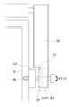
이하 본 발명의 실시 예에 대하여 첨부된 도면을 참조하여 그 구성 및 작용을 설명한다. 도 1 내지 도 4는 본 발명에 따른 다기능 지지구조체를 설명하는 도면이다. 도 1 내지 도 4에 도시된 바와 같이, 본 발명에 따른 다기능 지지구조체는 휴대장치(10)의 적어도 일측에 탈착 가능하게 결합되는 제1마찰부(110)를 포함한다.DETAILED DESCRIPTION OF THE PREFERRED EMBODIMENTS The present invention will now be described in detail with reference to the accompanying drawings. 1 to 4 are views for explaining a multifunctional support structure according to the present invention. 1 to 4, the multifunctional support structure according to the present invention includes a
또한, 끝부가 휴대장치(10)의 적어도 일측에 배치되며, 휴대장치(10)를 지지면에 대해 지지하는 지지부(130)를 포함한다. 또한, 지지부(130)의 끝부와 제1마찰부(110)의 사이에 배치되며, 제1마찰부(110)에 비해 경질인 제2마찰부(120)를 포함한다. 또한, 지지부(130)의 끝부, 제1마찰부(110) 및 제2마찰부(120)에 관통결합되는 결합부(140)를 포함한다.The end portion is disposed on at least one side of the
본 발명에 따른 다기능 지지구조체의 제1마찰부(110)는 휴대장치(10)의 일측에 결합되어 제2마찰부(120)와 접할 수 있으며, 지지부(130)의 끝부가 휴대장치(10)의 일측에 결합되어 제2마찰부(120) 및 제1마찰부(110)와 관통결합될 수 있다. 아울러, 본 발명에 따른 다기능 지지구조체의 제1마찰부(110)는 휴대장치(10)의 양측에 각각 결합되고, 각각의 제1마찰부(110)에 제2마찰부(120)가 각각 접하고, 각각의 제2마찰부(120)와 각각의 제1마찰부(110) 및 휴대장치(10)의 양측에 지지부(130)의 끝부가 각각 결합될 수 있다.The first
도 1 내지 도 4에서는 제1마찰부(110)가 휴대장치(10)의 양측에 각각 탈착가능하게 결합되고, 각각의 제1마찰부(110)에 제2마찰부(120)가 각각 접하며, 지지부(130)의 끝부가 각각의 제1마찰부(110) 및 제2마찰부(120)에 관통결합하며 휴대장치(10)의 양측에 결합되는 것을 중심으로 설명한다.1 to 4, the first
본 발명에 따른 다기능 지지구조체의 지지부(130)는 제1마찰부(110)에 의해 휴대장치에 결합되어 회동된다. 또한, 제1마찰부(110)를 향하는 제2마찰부(120)의 측면에 복수의 돌기(121)가 구비되며, 제1마찰부(110)와 제2마찰부(120)가 대면접촉 시 돌기(121)가 제1마찰부(110)에 인입되며 마찰력이 발생되어 지지부(130)의 회동이 저지된다.The
본 명세서에서 휴대장치(10)는 노트북 컴퓨터, 태블릿PC(tablet PC), PDA(Personal Digital Assistants) 및 스마트폰 등을 의미한다. 본 명세서는 태블릿PC를 중심으로 설명하며 도시하고 있다.In this specification, the
본 발명에 따른 다기능 지지구조체는 예를 들어 휴대장치(10) 중 노트북 컴퓨터에 결합시켜 노트북 컴퓨터를 지지하도록 할 수 있다. 또한, 노트북 컴퓨터에 결합시켰던 다기능 지지구조체를 탈거시켜 태블릿PC에 결합시켜 태블릿PC를 지지하도록 할 수도 있다. 다기능 지지구조체의 색상 및 크기는 어느 하나에 국한되지 않는다.The multifunctional support structure according to the present invention may be coupled to, for example, a notebook computer among the
본 발명에서 제1마찰부(110)는 실리콘 소재와 같은 연질이며, 제2마찰부(120)는 제1마찰부(110) 보다 상대적으로 경질로 이루어진다. 제1마찰부(110)의 소재는 어느 하나에 국한되지 않으며, 제1마찰부(110) 보다 연질인 소재이면 바람직하다. 제1마찰부(110)는 휴대장치(10)의 양측에 접착제를 이용하여 탈착 가능하게 결합된다. 나아가, 제1마찰부(110)는 습기가 있으면 접착력을 가지게 되는 소재로 이루어져 별도의 접착제를 이용하지 않고 휴대장치(10)의 양측에 탈착되게 결합가능하다. 아울러, 제1마찰부(110)는 벨크로(Velcro)에 의해 휴대장치(10)의 양측에 결합될 수도 있다.In the present invention, the
제1마찰부(110) 및 제2마찰부(120)의 형상은 원형, 사각형 및 삼각형 등으로 이루어질 수 있다. 또한, 제1마찰부(110) 및 제2마찰부(120)는 복수로 이루어져 휴대장치(10)의 양측 형상에 따라 교체되어 사용될 수 있다. 예를 들어, 휴대장치(10)의 양측이 직사각형의 평면으로 이루어진 경우, 제1마찰부(110) 및 제2마찰부(120)는 사각형으로 이루어진 것을 사용할 수 있다.The shape of the
또한, 휴대장치(10)의 양측이 사각형의 평면으로 이루어지더라도 제1마찰부(110) 및 제2마찰부(120)는 원형으로 이루어진 것을 사용할 수 있다. 제1마찰부(110) 및 제2마찰부(120)의 형상이 원형으로 이루어졌다고 하여 양측이 원형의 평면으로 이루어진 휴대장치(10)에만 사용되지는 않는다. 또한, 제1마찰부(110)와 제2마찰부(120)는 서로 동일한 형상으로 이루어져 결합부(140)에 의해 결합될 수 있으며, 서로 상이한 형상으로 이루어져 결합될 수도 있다.In addition, even if both sides of the
본 발명에서 제2마찰부(120)는 제1마찰부(110)와 접하며, 지지부(130)의 회동을 저지한다. 제2마찰부(120)는 결합부(140)와 관통결합하고, 결합부(140)의 구동에 의해 제1마찰부(110)와 접하거나 접하지 않게 된다. 제2마찰부(120)는 지지부(130)의 끝부와 제1마찰부(110)의 사이 공간에 배치된다. 제2마찰부(120)는 제1마찰부(110)를 향하는 측면에 복수의 돌기(121)를 형성한다. 돌기(121)들은 패턴을 형성하며 배치될 수 있으며, 패턴이 없이 배치될 수 있다.In the present invention, the second
제2마찰부(121)의 돌기(121)는 제2마찰부(120)에 코팅되어 제2마찰부(121)에 구비될 수 있으며, 접착물질을 이용해 제2마찰부(121)에 구비될 수 있다. 제2마찰부(121)는 돌기(121)를 가지는 사포로도 이루어질 수 있다. 돌기(121)의 형상 및 크기 등은 어느 하나에 국한되지 않는다.The
도 2 내지 도 4, 도 6 및 도 7은 제1마찰부(110)와 제2마찰부(120)가 서로 접하지 않은 상태를 도시한 것이다. 도시된 바와 같이, 제2마찰부(120)는 지지부(130)의 끝부에 구비된다. 제2마찰부(120)는 지지부(130)의 끝부에 일체형 또는 분리형으로 이루어질 수 있다.FIGS. 2 to 4, FIG. 6, and FIG. 7 illustrate a state in which the first rubbing
예를 들어, 제2마찰부(120)는 제1마찰부(110)를 향하는 지지부(130)의 끝부에 돌기(121)를 포함하는 물질이 코팅되어 구현될 수 있다. 지지부(130)의 끝부에 돌기(121)를 포함하는 물질이 코팅되어 제2마찰부(120)는 돌기(121)를 포함하는 코팅층으로 이루어질 수 있다. 코팅층(미도시)의 두께는 어느 하나에 국한되지 않으며, 경질의 성질을 가질 수 있는 물질로 이루어질 수 있다.For example, the
지지부(130)는 휴대장치(10)를 지지면에 대해 지지하며 휴대장치와 결합된 상태에서 회동하거나 회동저지된다. 여기서, 지지면은 휴대장치(10)가 책상에 지지될 경우 책상의 바닥면이되며, 휴대장치(10)가 벽에 지지될 경우 벽면이 된다.The
지지부(130)는 ‘]’ 또는 ‘」’자 형태로 이루어져 양 끝부가 휴대장치(10)의 양측에 배치되고, 양 끝부가 결합부(140)에 의해 제1마찰부(110), 제2마찰부(120)와 서로 결합된다. 지지부(130)는 탄성을 가진 소재로 이루어질 수 있다. 따라서, 결합부(140)의 구동에 의해 지지부(130)의 끝부가 소정의 범위만큼 이동되어 제1마찰부(110)와 제2마찰부(120)가 접할 수 있다.The
아울러, 지지부(130)에서 지지면에 접하는 부분에 길이 조절부(미도시)를 형성하여, 지지부(130)의 양 끝부 사이의 간격을 조절할 수 있다. 길이 조절부는 지지부(130)에서 지지면에 접하는 부분을 구분시켜 일 부분이 타 부분으로 인입되거나 인출되어, 지지부(130)에서 지지면에 접하는 부분의 길이를 조절할 수 있다. 따라서, 본 발명에 따른 다기능 지지구조체는 다양한 크기의 휴대장치(10)를 지지할 수 있다.In addition, a length adjusting portion (not shown) may be formed at a portion of the supporting
도 2 내지 도 4는 본 발명에 따른 다기능 지지구조체를 보다 상세히 설명하는 도면이다. 본 명세서에서는 휴대장치(10)의 일측을 도면으로 도시하고, 휴대장치(10)의 일측에 구비되는 다기능 지지구조체를 중심으로 설명한다. 도시된 바와 같이, 제1마찰부(110)는 휴대장치(10)의 측부에 결합된다. 또한, 끝부가 제1마찰부(110)를 향하는 지지부(130)가 휴대장치(10)의 측부에 배치된다. 제2마찰부(120)는 지지부(130)의 양 끝부와 제1마찰부(110)의 사이에 배치된다. 결합부(140)는 지제1마찰부(110), 제2마찰부(120) 및 지지부(130)의 양 끝부에 관통되어 결합된다.2 to 4 are views for explaining the multifunctional support structure according to the present invention in more detail. In the present specification, one side of the
도 2 및 도 3과 같이 휴대장치(10)의 양측을 향하는 결합부(140)의 끝부는 휴대장치(10)의 양측에 결합되어 회전구동 또는 지렛대 구동된다. 결합부(140)는 회전구동되어 휴대장치(10)의 양측에 인입 또는 인출된다. 결합부(140)가 휴대장치(10)의 양측에 인입될 때, 지지부(130)의 끝부는 제1마찰부(110) 쪽으로 이동되고, 이로 인해 제2마찰부(120)가 제1마찰부(110)와 접하게 된다.2 and 3, the ends of the engaging
도 2 및 도 3과 같이 휴대장치(10)의 양측을 향하는 결합부(140)의 끝부는 휴대장치(10)의 양측에 결합되기 위해서는 휴대장치(110)의 양측에 홈이 형성되어 있어야 한다. 휴대장치(110)의 양측에 형성된 홈은 휴대장치(110)의 제조과정에서 형성시키거나, 제조 후에 별도로 형성시킬 수 있다. 이때, 홈은 너트(nut)와 같은 구조로 이루어져 결합부(140)의 끝부와 볼트 및 너트 결합구조로 결합될 수 있다.As shown in FIGS. 2 and 3, the ends of the engaging
도 2와 같이, 결합부(140)가 화살표 방향으로 회전구동 시, 결합부(140)의 외부면에 형성되는 스크루(screw)를 따라 지지부(130)가 이동하여, 제1마찰부(110)와 제2마찰부(120)가 대면접촉되며 지지부(130)의 회동이 저지된다. 아울러, 도 3과 같이, 결합부(140)가 화살표 방향으로 지렛대구동 시, 지렛대 구동을 위해 힘이 가해지는 방향으로 지지부(130)가 이동하여, 제1마찰부(110)와 제2마찰부(120)가 대면접촉되며 지지부(130)의 회동이 저지된다. 지렛대 구동 시 지지부(130)가 이동하는 방향은 결합부(140)의 길이방향이며, 휴대장치(10)의 내측 또는 외측 방향이다.2, when the engaging
본 발명에서 결합부(140)의 지렛대 구동을 위해 힘이 가해지는 방향은 휴대장치(10)의 외측 또는 내측이다. 결합부(140)의 지렛대 구동 시 휴대장치(10)의 내측으로 힘을 가하면 지지대(130)는 휴대장치(10)의 내측으로 이동되며, 결합부(140)의 지렛대 구동 시 휴대장치(10)의 외측으로 힘을 가하면 지지대(130)는 휴대장치(10)의 외측으로 이동된다.In the present invention, the direction in which the force is applied for driving the lever of the
지지부(130)가 휴대장치(10)의 내측으로 이동되면 제1마찰부(110)는 제2마찰부(120)와 접하고, 지지부(130)가 휴대장치(10)의 외측으로 이동되면 제1마찰부(110)는 제2마찰부(120)에서 떨어져 간격을 형성하게 된다.When the
결합부(140)의 지렛대구동 시, 결합부(140)의 끝부는 제1마찰부(110)를 관통하여 휴대장치(10)의 양측에 홈에 결합된다. 이때, 홈은 너트(nut)와 같은 구조로 이루어져 결합부(140)의 끝부와 볼트 및 너트 결합구조로 결합될 수 있다.When the levers of the engaging
지지부(130)의 회동을 위해서는 지지부(130)의 회동 저지를 위해 결합부(140)가 회전구동된 방향에서 반대 방향으로 결합부(140)를 회전구동시키면 된다. 아울러, 지지부(130)의 회동을 위해서는 지지부(130)의 회동 저지를 위해 결합부(140)의 지렛대구동 시 가해졌던 힘의 방향에서 반대방향으로 힘을 가해 결합부(140)를 지렛대구동시키면 된다.In order to rotate the supporting
예를 들어, 결합부(140)를 시계방향으로 회동구동시켜 제1마찰부(110)와 제2마찰부(120)가 접하도록 하여 지지부(130)의 회동을 저지시켰다면, 결합부(140)를 반시계방향으로 회동구동시켜 제1마찰부(110)와 제2마찰부(120)가 서로 떨어지도록 하여 지지부(130)를 회동시킬 수 있다. 아울러, 결합부(140)를 지렛대구동으로 구동 시 힘을 제1마찰부(110) 방향으로 가해 제1마찰부(110)와 제2마찰부(120)가 접하도록 하여 지지부(130)의 회동을 저지시켰다면, 결합부(140)를 지렛대구동으로 구동 시 힘을 제1마찰부(110) 방향과 반대 방향으로 가해 제1마찰부(110)와 제2마찰부(120)가 서로 떨어지도록 하여 지지부(130)를 회동시킬 수 있다.For example, if the
도 4에 도시된 바와 같이, 제1마찰부(110)를 향하는 결합부(140)의 끝부는 제1마찰부(110)에 결합될 수 있다. 결합부(140)의 끝부가 제1마찰부(110)에 결합되기 위해, 제1마찰부(110)는 결합부재(141)를 구비한다. 휴대장치(10)의 양측을 향하는 결합부(140)의 끝부는 제1마찰부(110)에 구비되는 결합부재(141)와 결합되어 제1마찰부(110)와 결합되고, 회전구동 또는 지렛대 구동된다.4, an end portion of the engaging
제1마찰부(110)에 구비되는 결합부재(141)는 너트(nut)로 이루어질 수 있다. 한편, 결합부재(141)는 제1마찰부(110)를 향하는 결합부(140)의 끝부와 일체형으로 이루어질 수 있다. 결합부(140)의 끝부는 결합부재(141)가 너트로 이루어진 경우, 회동구동 시 결합부(140)의 외면에 형성된 나사선에 의해 결합부재(141)에 인입 또는 인출되며, 제1마찰부(110)와 제2마찰부(120)가 서로 접하거나 떨어지도록 한다.The engaging
결합부(140)와 결합부재(141)가 일체형으로 이루어진 경우, 결합부(140)는 지렛대구동으로 제1마찰부(110)와 제2마찰부(120)가 서로 접하거나 떨어지도록 한다. 결합부(140)는 기본적으로 막대구조로 이루어지며, 단면 형상이 다양하게 이루어질 수 있다.When the engaging
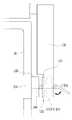
도 5 내지 도 7은 본 발명에 따른 거치부를 구비한 다기능 지지구조체를 설명하는 도면이다. 도 5 내지 도 7에 도시된 다기능 지지구조체는 휴대장치(10)의 적어도 일측에 탈착 가능하게 결합되는 거치부(210)를 포함한다. 거치부(210)는 휴대장치(10)의 일측에만 구비될 수 있고, 휴대장치(10)의 양측에 모두 구비될 수 있다. 도 5 내지 도 7에서는 휴대장치(10)의 양측에 거치부(210)가 구비된 것을 중심으로 설명한다.5 to 7 are views illustrating a multifunctional support structure having a mounting portion according to the present invention. The multifunctional support structure shown in Figs. 5-7 includes a
거치부(210)는 집게 구조로 이루어져, 휴대장치(10)의 양측에 탈착된다. 본 발명에 따른 다기능 지지구조체가 거치부(210)를 구비하므로, 제1마찰부(110)는 휴대장치(10)의 적어도 일측에 결합된 거치부(210)에 부착되거나 일체형으로 결합된다.The mounting
거치부(210)가 구비된 다기능 지지구조체에서 지지부(130)의 끝부는 제1마찰부(110)를 향하도록 배치되며, 제2마찰부(120)는 제1마찰부(110)와 지지부(130)의 끝부 사이에 배치되어 결합부(140)와 관통결합된다. 도 6에 도시된 바와 같이, 거치부(210)를 향하는 결합부(140)의 끝부는 거치부(210)에 결합되어 회전구동 또는 지렛대 구동된다.In the multifunctional support structure provided with the mounting
아울러, 제1마찰부(110)를 향하는 결합부(140)의 끝부는 제1마찰부(110)에 구비되는 결합부재(141)와 결합되어 제1마찰부(110)와 결합되고, 회전구동 또는 지렛대 구동된다. 도 6과 같이, 결합부(140)가 거치부(210)에 결합된 상태에서 지렛대 구동되면, 거치부(210)와 결합된 결합부(140)의 끝부는 결합부재(141)와 일체형으로 이루어진다.The end of the
또한, 도 7과 같이 결합부(140)의 끝부가 결합부재(141)와 일체형으로 이루어져, 결합부(140)는 지렛대 구동으로 제1마찰부(110) 및 제2마찰부(120)가 서로 접촉되거나 떨어지게 하여 지지부(130)를 회동 또는 회동저지되도록 한다. 결합부(140)의 회전구동 또는 지렛대 구동에 의한 제1마찰부(110)와 제2마찰부(120)의 접촉, 접촉에 따른 지지부(130)의 회동저지에 대한 설명은 도 1 내지 도 4를 통해 설명한 바와 동일하므로 생략 가능하다.7, an end portion of the
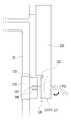
도 8은 본 발명에 따른 다기능 지지구조체를 설명하는 다른 도면이다. 도 8에 도시된 바와 같이, 본 발명에 따른 다기능 지지구조체는 제1마찰부(110)와 제2마찰부(120)가 복수로 구비될 수 있다. 제1마찰부(110) 및 제2마찰부(120)는 단위 마찰부로 구성되며, 이때 단위 마찰부가 반복적으로 구비되어 결합부(140)에 의해 관통결합된다. 단위 마찰부가 반복적으로 구비될 경우, 일 단위 마찰부에서 돌기가 구비되지 않는 제2마찰부(120)의 측면은 타 단위 마찰부에서 제1마찰부(110)의 측면과 접하게 된다.8 is another view for explaining a multifunctional support structure according to the present invention. As shown in FIG. 8, the multifunctional support structure according to the present invention may include a plurality of the
아울러, 일 단위 마찰부와 타 단위 마찰부가 반복적으로 구비될 경우, 결합부(140)와 결합되는 결합부재(141)는 일 단위 마찰부의 제1마찰부(110)에만 구비된다. 본 발명에서 단위 마찰부는 거치부(210)가 구비된 경우에도 구현될 수 있다. 본 발명에서 거치부(210)가 구비된 경우, 일 단위 마찰부의 제1마찰부(110)가 거치부(210)의 측면에 결합되며 제2마찰부(120)와 접하게 되며 단위 마찰부를 구현하게 된다.Further, when the one-unit friction portion and the other-unit friction portion are repeatedly provided, the
본 발명에서 단위 마찰부의 개수는 어느 하나에 국한되지 않으며, 단위 마찰부의 형상 및 크기 등은 어느 하나에 국한되지 않는다. 본 발명은 제1마찰부(110) 및 제2마찰부(120)를 단위 마찰부로 구성하여 복수개로 구비되도록 하므로, 제1마찰부(110) 및 제2마찰부(120)가 서로 접할 때 발생되는 마찰력을 증가시킬 수 있다.In the present invention, the number of unit friction portions is not limited to any one, and the shape and size of the unit friction portion are not limited to any one. Since the
본 발명에 따른 다기능 지지구조체는 연질의 제1마찰부(110)가 휴대장치(10)의 양측에 탈착 가능하게 구비되며, 결합부(140)에 의해 제1마찰부(110), 지지부(130) 및 경질의 제2마찰부(120)가 서로 결합되어 휴대장치(10)를 지지면에 대해 지지하므로, 특정 기종에 국한되지 않고 다양한 기종의 휴대장치에 체결된 상태에서 지지를 가능하게 한다.The multifunctional support structure according to the present invention is characterized in that a soft first rubbing
또한, 제1마찰부(110)에 비해 경질인 제2마찰부(120)의 표면에 복수의 돌기(121)를 구비하며, 결합부(140)의 회전구동 또는 지렛대구동으로 제1마찰부(110)가 결합부(140)의 길이 방향으로 이동하여 제1마찰부(110)와 제2마찰부(120)가 접촉할 때 돌기(121)가 제1마찰부(110)에 인입되며 마찰력을 발생시켜 지지부의 회동을 저지하므로, 휴대장치에 체결된 상태에서 무단(無段)으로 지지각도를 조절할 수 있다.The plurality of
본 실시 예 및 본 명세서에 첨부된 도면은 본 발명에 포함되는 기술적 사상의 일부를 명확하게 나타내고 있는 것에 불과하며, 본 발명의 명세서 및 도면에 포함된 기술적 사상의 범위 내에서 당업자가 용이하게 유추할 수 있는 변형 예와 구체적인 실시 예는 모두 본 발명의 권리범위에 포함되는 것이 자명하다고 할 것이다.It is to be understood that both the foregoing general description and the following detailed description of the present invention are exemplary and explanatory and are intended to provide further explanation of the invention as claimed. It will be understood that variations and specific embodiments which may occur to those skilled in the art are included within the scope of the present invention.
10: 휴대장치110: 제1마찰부
120: 제2마찰부121: 돌기
130: 지지부140: 결합부
141: 결합부재150: 접착부재
210: 거치부10: Portable device 110: First friction part
120: second frictional portion 121: projection
130: support part 140:
141: coupling member 150: adhesive member
210:
Claims (13)
Translated fromKorean지지부는 휴대장치에 결합되어 회동되고, 제1마찰부를 향하는 제2마찰부의 측면에 복수의 돌기가 구비되며, 제1마찰부와 제2마찰부가 접촉 시 돌기가 제1마찰부에 인입되며 마찰력이 발생되어 지지부의 회동이 저지되며,
휴대장치의 적어도 일측을 향하는 결합부의 끝부는 휴대장치의 적어도 일측에 결합되어 회전구동 또는 지렛대 구동되며,
결합부의 회전구동 시, 결합부의 외부면에 형성되는 스크루(screw)를 따라 지지부가 이동하여, 제1마찰부와 제2마찰부가 접촉되며 지지부의 회동이 저지되는 것을 특징으로 하는 다기능 지지구조체.At least one first frictional portion detachably coupled to at least one side of the portable device; A support disposed on at least one side of the portable device and supporting the portable device with respect to the support surface; At least one second frictional portion disposed between the end portion of the support and the first frictional portion and harder than the first frictional portion; And a coupling portion penetratingly coupled to the end portion of the support portion, the first friction portion and the second friction portion,
The support portion is coupled to the portable device and is rotated. A plurality of projections are provided on a side surface of the second frictional portion facing the first frictional portion. When the first frictional portion and the second frictional portion contact each other, the projections are drawn into the first frictional portion, The rotation of the support portion is prevented,
The end of the engaging portion facing at least one side of the portable device is coupled to at least one side of the portable device and is rotationally driven or lever-driven,
Wherein when the engaging portion is rotated, the supporting portion moves along a screw formed on the outer surface of the engaging portion so that the first friction portion and the second friction portion contact each other and the rotation of the supporting portion is blocked.
지지부는 휴대장치에 결합되어 회동되고, 제1마찰부를 향하는 제2마찰부의 측면에 복수의 돌기가 구비되며, 제1마찰부와 제2마찰부가 접촉 시 돌기가 제1마찰부에 인입되며 마찰력이 발생되어 지지부의 회동이 저지되며,
휴대장치의 적어도 일측을 향하는 결합부의 끝부는 휴대장치의 적어도 일측에 결합되어 회전구동 또는 지렛대 구동되며,
결합부의 지렛대구동 시, 지렛대 구동을 위해 지지부가 휴대장치의 내측으로 이동하여, 제1마찰부와 제2마찰부가 접촉되며 지지부의 회동이 저지되는 것을 특징으로 하는 다기능 지지구조체.At least one first frictional portion detachably coupled to at least one side of the portable device; A support disposed on at least one side of the portable device and supporting the portable device with respect to the support surface; At least one second frictional portion disposed between the end portion of the support and the first frictional portion and harder than the first frictional portion; And a coupling portion penetratingly coupled to the end portion of the support portion, the first friction portion and the second friction portion,
The support portion is coupled to the portable device and is rotated. A plurality of projections are provided on a side surface of the second frictional portion facing the first frictional portion. When the first frictional portion and the second frictional portion contact each other, the projections are drawn into the first frictional portion, The rotation of the support portion is prevented,
The end of the engaging portion facing at least one side of the portable device is coupled to at least one side of the portable device and is rotationally driven or lever-driven,
Wherein when the levers of the engaging portion are driven, the supporting portion moves to the inside of the portable device for driving the lever, and the first frictional portion and the second frictional portion come into contact with each other to prevent the rotation of the supporting portion.
지지부는 휴대장치에 결합되어 회동되고, 제1마찰부를 향하는 제2마찰부의 측면에 복수의 돌기가 구비되며, 제1마찰부와 제2마찰부가 접촉 시 돌기가 제1마찰부에 인입되며 마찰력이 발생되어 지지부의 회동이 저지되며,
휴대장치의 적어도 일측을 향하는 결합부의 끝부는 제1마찰부에 구비되는 결합부재와 결합되어 제1마찰부와 결합되고, 회전구동 또는 지렛대 구동되는 것을 특징으로 하는 다기능 지지구조체.At least one first frictional portion detachably coupled to at least one side of the portable device; A support disposed on at least one side of the portable device and supporting the portable device with respect to the support surface; At least one second frictional portion disposed between the end portion of the support and the first frictional portion and harder than the first frictional portion; And a coupling portion penetratingly coupled to the end portion of the support portion, the first friction portion and the second friction portion,
The support portion is coupled to the portable device and is rotated. A plurality of projections are provided on a side surface of the second frictional portion facing the first frictional portion. When the first frictional portion and the second frictional portion contact each other, the projections are drawn into the first frictional portion, The rotation of the support portion is prevented,
Characterized in that the end of the engaging portion facing at least one side of the portable device is engaged with the engaging member provided on the first frictional portion and engaged with the first frictional portion, and is rotationally driven or lever-driven.
결합부의 회전구동 또는 지렛대 구동 시,
지지부가 휴대장치의 내측으로 이동하여, 제1마찰부와 제2마찰부가 접촉되며 지지부의 회동이 저지되는 것을 특징으로 하는 다기능 지지구조체.The method of claim 5,
When the engaging portion is rotated or leaned,
The supporting portion moves to the inside of the portable device, and the first frictional portion and the second frictional portion come into contact with each other, and rotation of the supporting portion is blocked.
지지부는 거치부에 의해 휴대장치에 결합되어 회동되고, 제1마찰부를 향하는 제2마찰부의 측면에 복수의 돌기가 구비되며, 제1마찰부와 제2마찰부가 접촉 시 돌기가 제1마찰부에 인입되며 마찰력이 발생되어 지지부의 회동이 저지되며,
제2마찰부는 돌기를 포함하는 코팅층으로 이루어지거나, 제1마찰부 및 제2마찰부는 단위 마찰부로 구성되며 상기 단위 마찰부가 반복적으로 구비되어 결합부에 의해 관통결합되는 것을 특징으로 하는 다기능 지지구조체.A mounting part detachably coupled to at least one side of the portable device; At least one first friction portion coupled to a side surface of the mounting portion that is not in contact with at least one side of the portable device; A support disposed on at least one side of the portable device and supporting the portable device with respect to the support surface; At least one second frictional portion disposed between the end portion of the support and the first frictional portion and harder than the first frictional portion; And a coupling portion penetratingly coupled to the end portion of the support portion, the first friction portion and the second friction portion,
The supporting portion is coupled to the portable device by the mounting portion and is rotated. A plurality of projections are provided on a side surface of the second friction portion facing the first friction portion. When the first friction portion and the second friction portion come into contact with each other, A frictional force is generated and rotation of the support portion is prevented,
Wherein the first friction portion and the second friction portion are constituted by a unit friction portion, and the unit friction portion is repeatedly provided and penetrated by the coupling portion.
거치부를 향하는 결합부의 끝부는
거치부에 결합되어 지렛대 구동되는 것을 특징으로 하는 다기능 지지구조체.The method of claim 7,
The end portion of the engaging portion facing the mounting portion
Characterized in that the multifunctional support structure is coupled to the lever and is driven by the lever.
결합부의 지렛대 구동 시,
지지부가 휴대장치의 내측으로 이동하여, 제1마찰부와 제2마찰부가 접촉되며 지지부의 회동이 저지되는 것을 특징으로 하는 다기능 지지구조체.Claim 8
When driving the lever of the engaging portion,
The supporting portion moves to the inside of the portable device, and the first frictional portion and the second frictional portion come into contact with each other, and rotation of the supporting portion is blocked.
제1마찰부를 향하는 결합부의 끝부는
제1마찰부에 구비되는 결합부재와 결합되어 제1마찰부와 결합되고, 회전구동 또는 지렛대 구동되는 것을 특징으로 하는 다기능 지지구조체.The method of claim 7,
The end portion of the engaging portion facing the first friction portion
Wherein the first friction portion is engaged with the engagement member provided on the first friction portion and is engaged with the first friction portion, and is rotationally driven or lever-driven.
지지부는 휴대장치에 결합되어 회동되고, 제1마찰부를 향하는 제2마찰부의 측면에 복수의 돌기가 구비되며, 제1마찰부와 제2마찰부가 접촉 시 돌기가 제1마찰부에 인입되며 마찰력이 발생되어 지지부의 회동이 저지되며,
제2마찰부는 돌기를 포함하는 코팅층으로 이루어진 것을 특징으로 하는 다기능 지지구조체.At least one first frictional portion detachably coupled to at least one side of the portable device; A support disposed on at least one side of the portable device and supporting the portable device with respect to the support surface; At least one second frictional portion disposed between the end portion of the support and the first frictional portion and harder than the first frictional portion; And a coupling portion penetratingly coupled to the end portion of the support portion, the first friction portion and the second friction portion,
The support portion is coupled to the portable device and is rotated. A plurality of projections are provided on a side surface of the second frictional portion facing the first frictional portion. When the first frictional portion and the second frictional portion contact each other, the projections are drawn into the first frictional portion, The rotation of the support portion is prevented,
And the second frictional portion comprises a coating layer including projections.
지지부는 휴대장치에 결합되어 회동되고, 제1마찰부를 향하는 제2마찰부의 측면에 복수의 돌기가 구비되며, 제1마찰부와 제2마찰부가 접촉 시 돌기가 제1마찰부에 인입되며 마찰력이 발생되어 지지부의 회동이 저지되며,
제1마찰부 및 제2마찰부는
단위 마찰부로 구성되며, 상기 단위 마찰부가 반복적으로 구비되어 결합부에 의해 관통결합되는 것을 특징으로 하는 다기능 지지구조체.At least one first frictional portion detachably coupled to at least one side of the portable device; A support disposed on at least one side of the portable device and supporting the portable device with respect to the support surface; At least one second frictional portion disposed between the end portion of the support and the first frictional portion and harder than the first frictional portion; And a coupling portion penetratingly coupled to the end portion of the support portion, the first friction portion and the second friction portion,
The support portion is coupled to the portable device and is rotated. A plurality of projections are provided on a side surface of the second frictional portion facing the first frictional portion. When the first frictional portion and the second frictional portion contact each other, the projections are drawn into the first frictional portion, The rotation of the support portion is prevented,
The first friction portion and the second friction portion
And a unit friction portion, wherein the unit friction portion is repeatedly provided to be engaged with the coupling portion.
상기 단위 마찰부가 반복적으로 구비될 경우,
일 단위 마찰부에서 돌기가 구비되지 않는 제2마찰부의 측면은 타 단위 마찰부에서 제1마찰부의 측면과 접하게 되는 것을 특징으로 하는 다기능 지지구조체.The method according to claim 7 or 12,
When the unit friction portion is repeatedly provided,
And the side surface of the second friction portion, which is not provided with the projection in the daily frictional portion, is brought into contact with the side surface of the first frictional portion in the other unit friction portion.
Priority Applications (1)
| Application Number | Priority Date | Filing Date | Title |
|---|---|---|---|
| KR1020140023312AKR101565335B1 (en) | 2014-02-27 | 2014-02-27 | Supporting structure having multifunction |
Applications Claiming Priority (1)
| Application Number | Priority Date | Filing Date | Title |
|---|---|---|---|
| KR1020140023312AKR101565335B1 (en) | 2014-02-27 | 2014-02-27 | Supporting structure having multifunction |
Publications (2)
| Publication Number | Publication Date |
|---|---|
| KR20150101698A KR20150101698A (en) | 2015-09-04 |
| KR101565335B1true KR101565335B1 (en) | 2015-11-05 |
Family
ID=54242763
Family Applications (1)
| Application Number | Title | Priority Date | Filing Date |
|---|---|---|---|
| KR1020140023312AExpired - Fee RelatedKR101565335B1 (en) | 2014-02-27 | 2014-02-27 | Supporting structure having multifunction |
Country Status (1)
| Country | Link |
|---|---|
| KR (1) | KR101565335B1 (en) |
Citations (2)
| Publication number | Priority date | Publication date | Assignee | Title |
|---|---|---|---|---|
| KR200330219Y1 (en) | 2003-07-15 | 2003-10-17 | 정재봉 | Handsfree for Portable Telephone |
| JP2013529449A (en)* | 2010-06-07 | 2013-07-18 | ターガス・グループ・インターナショナル・インコーポレイテッド | Case accessories for portable electronic devices and related systems and methods |
- 2014
- 2014-02-27KRKR1020140023312Apatent/KR101565335B1/ennot_activeExpired - Fee Related
Patent Citations (2)
| Publication number | Priority date | Publication date | Assignee | Title |
|---|---|---|---|---|
| KR200330219Y1 (en) | 2003-07-15 | 2003-10-17 | 정재봉 | Handsfree for Portable Telephone |
| JP2013529449A (en)* | 2010-06-07 | 2013-07-18 | ターガス・グループ・インターナショナル・インコーポレイテッド | Case accessories for portable electronic devices and related systems and methods |
Also Published As
| Publication number | Publication date |
|---|---|
| KR20150101698A (en) | 2015-09-04 |
Similar Documents
| Publication | Publication Date | Title |
|---|---|---|
| US9512655B2 (en) | Hinge structure | |
| CN101886661B (en) | Hinge structure and electronic device support seat using same | |
| JP3169418U (en) | Angle adjustable support frame | |
| TWI597592B (en) | Docking station and electrical apparatus | |
| US20120112022A1 (en) | Wall mount hanger | |
| US20190274228A1 (en) | Support mechanism and mobile terminal | |
| KR102168145B1 (en) | Hinge mechanism for rotatable component attachment | |
| US9032590B2 (en) | Rotating mechanism and electronic device with same | |
| US20130126688A1 (en) | Support frame for electronic device | |
| US20120262853A1 (en) | Electronic device with support assembly | |
| US9999296B1 (en) | Laptop PC stand | |
| US8602375B2 (en) | Portable and foldable support bracket | |
| CN105765480B (en) | Rotate-to-translate locking hinge | |
| CN102537621A (en) | Electronic device bracket and electronic equipment with same | |
| TWM464715U (en) | Fixing device for fixing a portable electronic device and portable electronic apparatus therewith | |
| CN204191025U (en) | A kind of board positioning means | |
| US20120025682A1 (en) | Foldable device | |
| TW201329673A (en) | Portable electronic device and docking thereof | |
| TW201304663A (en) | Supporting apparatus of electronic device | |
| CN104125740A (en) | Fixture | |
| TW201413147A (en) | Display device | |
| TW201345254A (en) | Display having pivot constraint function | |
| CN205120394U (en) | Tilt Angle Test Bench | |
| KR101565335B1 (en) | Supporting structure having multifunction | |
| TWI557538B (en) | Portable electronic device |
Legal Events
| Date | Code | Title | Description |
|---|---|---|---|
| A201 | Request for examination | ||
| PA0109 | Patent application | St.27 status event code:A-0-1-A10-A12-nap-PA0109 | |
| PA0201 | Request for examination | St.27 status event code:A-1-2-D10-D11-exm-PA0201 | |
| P11-X000 | Amendment of application requested | St.27 status event code:A-2-2-P10-P11-nap-X000 | |
| P13-X000 | Application amended | St.27 status event code:A-2-2-P10-P13-nap-X000 | |
| D13-X000 | Search requested | St.27 status event code:A-1-2-D10-D13-srh-X000 | |
| D14-X000 | Search report completed | St.27 status event code:A-1-2-D10-D14-srh-X000 | |
| E902 | Notification of reason for refusal | ||
| PE0902 | Notice of grounds for rejection | St.27 status event code:A-1-2-D10-D21-exm-PE0902 | |
| E13-X000 | Pre-grant limitation requested | St.27 status event code:A-2-3-E10-E13-lim-X000 | |
| P11-X000 | Amendment of application requested | St.27 status event code:A-2-2-P10-P11-nap-X000 | |
| P13-X000 | Application amended | St.27 status event code:A-2-2-P10-P13-nap-X000 | |
| E701 | Decision to grant or registration of patent right | ||
| PE0701 | Decision of registration | St.27 status event code:A-1-2-D10-D22-exm-PE0701 | |
| PG1501 | Laying open of application | St.27 status event code:A-1-1-Q10-Q12-nap-PG1501 | |
| PR0701 | Registration of establishment | St.27 status event code:A-2-4-F10-F11-exm-PR0701 | |
| PR1002 | Payment of registration fee | St.27 status event code:A-2-2-U10-U11-oth-PR1002 Fee payment year number:1 | |
| R18-X000 | Changes to party contact information recorded | St.27 status event code:A-5-5-R10-R18-oth-X000 | |
| PG1601 | Publication of registration | St.27 status event code:A-4-4-Q10-Q13-nap-PG1601 | |
| LAPS | Lapse due to unpaid annual fee | ||
| PC1903 | Unpaid annual fee | St.27 status event code:A-4-4-U10-U13-oth-PC1903 Not in force date:20181029 Payment event data comment text:Termination Category : DEFAULT_OF_REGISTRATION_FEE | |
| PC1903 | Unpaid annual fee | St.27 status event code:N-4-6-H10-H13-oth-PC1903 Ip right cessation event data comment text:Termination Category : DEFAULT_OF_REGISTRATION_FEE Not in force date:20181029 |