KR101564559B1 - Nested expandable sleeve implant - Google Patents
Nested expandable sleeve implantDownload PDFInfo
- Publication number
- KR101564559B1 KR101564559B1KR1020107020006AKR20107020006AKR101564559B1KR 101564559 B1KR101564559 B1KR 101564559B1KR 1020107020006 AKR1020107020006 AKR 1020107020006AKR 20107020006 AKR20107020006 AKR 20107020006AKR 101564559 B1KR101564559 B1KR 101564559B1
- Authority
- KR
- South Korea
- Prior art keywords
- sleeve
- core element
- sleeves
- inflatable
- implant
- Prior art date
- Legal status (The legal status is an assumption and is not a legal conclusion. Google has not performed a legal analysis and makes no representation as to the accuracy of the status listed.)
- Expired - Fee Related
Links
Images


Classifications
- A—HUMAN NECESSITIES
- A61—MEDICAL OR VETERINARY SCIENCE; HYGIENE
- A61B—DIAGNOSIS; SURGERY; IDENTIFICATION
- A61B17/00—Surgical instruments, devices or methods
- A61B17/56—Surgical instruments or methods for treatment of bones or joints; Devices specially adapted therefor
- A61B17/58—Surgical instruments or methods for treatment of bones or joints; Devices specially adapted therefor for osteosynthesis, e.g. bone plates, screws or setting implements
- A61B17/88—Osteosynthesis instruments; Methods or means for implanting or extracting internal or external fixation devices
- A61B17/885—Tools for expanding or compacting bones or discs or cavities therein
- A61B17/8852—Tools for expanding or compacting bones or discs or cavities therein capable of being assembled or enlarged, or changing shape, inside the bone or disc
- A61B17/8858—Tools for expanding or compacting bones or discs or cavities therein capable of being assembled or enlarged, or changing shape, inside the bone or disc laterally or radially expansible
- A—HUMAN NECESSITIES
- A61—MEDICAL OR VETERINARY SCIENCE; HYGIENE
- A61B—DIAGNOSIS; SURGERY; IDENTIFICATION
- A61B17/00—Surgical instruments, devices or methods
- A61B17/56—Surgical instruments or methods for treatment of bones or joints; Devices specially adapted therefor
- A61B17/58—Surgical instruments or methods for treatment of bones or joints; Devices specially adapted therefor for osteosynthesis, e.g. bone plates, screws or setting implements
- A61B17/68—Internal fixation devices, including fasteners and spinal fixators, even if a part thereof projects from the skin
- A—HUMAN NECESSITIES
- A61—MEDICAL OR VETERINARY SCIENCE; HYGIENE
- A61F—FILTERS IMPLANTABLE INTO BLOOD VESSELS; PROSTHESES; DEVICES PROVIDING PATENCY TO, OR PREVENTING COLLAPSING OF, TUBULAR STRUCTURES OF THE BODY, e.g. STENTS; ORTHOPAEDIC, NURSING OR CONTRACEPTIVE DEVICES; FOMENTATION; TREATMENT OR PROTECTION OF EYES OR EARS; BANDAGES, DRESSINGS OR ABSORBENT PADS; FIRST-AID KITS
- A61F2/00—Filters implantable into blood vessels; Prostheses, i.e. artificial substitutes or replacements for parts of the body; Appliances for connecting them with the body; Devices providing patency to, or preventing collapsing of, tubular structures of the body, e.g. stents
- A61F2/02—Prostheses implantable into the body
- A61F2/30—Joints
- A61F2/44—Joints for the spine, e.g. vertebrae, spinal discs
- A61F2/4405—Joints for the spine, e.g. vertebrae, spinal discs for apophyseal or facet joints, i.e. between adjacent spinous or transverse processes
- A—HUMAN NECESSITIES
- A61—MEDICAL OR VETERINARY SCIENCE; HYGIENE
- A61F—FILTERS IMPLANTABLE INTO BLOOD VESSELS; PROSTHESES; DEVICES PROVIDING PATENCY TO, OR PREVENTING COLLAPSING OF, TUBULAR STRUCTURES OF THE BODY, e.g. STENTS; ORTHOPAEDIC, NURSING OR CONTRACEPTIVE DEVICES; FOMENTATION; TREATMENT OR PROTECTION OF EYES OR EARS; BANDAGES, DRESSINGS OR ABSORBENT PADS; FIRST-AID KITS
- A61F2/00—Filters implantable into blood vessels; Prostheses, i.e. artificial substitutes or replacements for parts of the body; Appliances for connecting them with the body; Devices providing patency to, or preventing collapsing of, tubular structures of the body, e.g. stents
- A61F2/02—Prostheses implantable into the body
- A61F2/30—Joints
- A61F2/44—Joints for the spine, e.g. vertebrae, spinal discs
- A61F2/442—Intervertebral or spinal discs, e.g. resilient
- A—HUMAN NECESSITIES
- A61—MEDICAL OR VETERINARY SCIENCE; HYGIENE
- A61F—FILTERS IMPLANTABLE INTO BLOOD VESSELS; PROSTHESES; DEVICES PROVIDING PATENCY TO, OR PREVENTING COLLAPSING OF, TUBULAR STRUCTURES OF THE BODY, e.g. STENTS; ORTHOPAEDIC, NURSING OR CONTRACEPTIVE DEVICES; FOMENTATION; TREATMENT OR PROTECTION OF EYES OR EARS; BANDAGES, DRESSINGS OR ABSORBENT PADS; FIRST-AID KITS
- A61F2/00—Filters implantable into blood vessels; Prostheses, i.e. artificial substitutes or replacements for parts of the body; Appliances for connecting them with the body; Devices providing patency to, or preventing collapsing of, tubular structures of the body, e.g. stents
- A61F2/02—Prostheses implantable into the body
- A61F2/30—Joints
- A61F2/44—Joints for the spine, e.g. vertebrae, spinal discs
- A61F2/4455—Joints for the spine, e.g. vertebrae, spinal discs for the fusion of spinal bodies, e.g. intervertebral fusion of adjacent spinal bodies, e.g. fusion cages
- A61F2/446—Joints for the spine, e.g. vertebrae, spinal discs for the fusion of spinal bodies, e.g. intervertebral fusion of adjacent spinal bodies, e.g. fusion cages having a circular or elliptical cross-section substantially parallel to the axis of the spine, e.g. cylinders or frustocones
- A—HUMAN NECESSITIES
- A61—MEDICAL OR VETERINARY SCIENCE; HYGIENE
- A61F—FILTERS IMPLANTABLE INTO BLOOD VESSELS; PROSTHESES; DEVICES PROVIDING PATENCY TO, OR PREVENTING COLLAPSING OF, TUBULAR STRUCTURES OF THE BODY, e.g. STENTS; ORTHOPAEDIC, NURSING OR CONTRACEPTIVE DEVICES; FOMENTATION; TREATMENT OR PROTECTION OF EYES OR EARS; BANDAGES, DRESSINGS OR ABSORBENT PADS; FIRST-AID KITS
- A61F2/00—Filters implantable into blood vessels; Prostheses, i.e. artificial substitutes or replacements for parts of the body; Appliances for connecting them with the body; Devices providing patency to, or preventing collapsing of, tubular structures of the body, e.g. stents
- A61F2/02—Prostheses implantable into the body
- A61F2/30—Joints
- A61F2/44—Joints for the spine, e.g. vertebrae, spinal discs
- A61F2002/4495—Joints for the spine, e.g. vertebrae, spinal discs having a fabric structure, e.g. made from wires or fibres
- Y—GENERAL TAGGING OF NEW TECHNOLOGICAL DEVELOPMENTS; GENERAL TAGGING OF CROSS-SECTIONAL TECHNOLOGIES SPANNING OVER SEVERAL SECTIONS OF THE IPC; TECHNICAL SUBJECTS COVERED BY FORMER USPC CROSS-REFERENCE ART COLLECTIONS [XRACs] AND DIGESTS
- Y10—TECHNICAL SUBJECTS COVERED BY FORMER USPC
- Y10S—TECHNICAL SUBJECTS COVERED BY FORMER USPC CROSS-REFERENCE ART COLLECTIONS [XRACs] AND DIGESTS
- Y10S623/00—Prosthesis, i.e. artificial body members, parts thereof, or aids and accessories therefor
- Y10S623/902—Method of implanting
Landscapes
- Health & Medical Sciences (AREA)
- Orthopedic Medicine & Surgery (AREA)
- Life Sciences & Earth Sciences (AREA)
- Surgery (AREA)
- Engineering & Computer Science (AREA)
- Biomedical Technology (AREA)
- Animal Behavior & Ethology (AREA)
- Veterinary Medicine (AREA)
- Public Health (AREA)
- Heart & Thoracic Surgery (AREA)
- General Health & Medical Sciences (AREA)
- Molecular Biology (AREA)
- Medical Informatics (AREA)
- Nuclear Medicine, Radiotherapy & Molecular Imaging (AREA)
- Neurology (AREA)
- Cardiology (AREA)
- Oral & Maxillofacial Surgery (AREA)
- Transplantation (AREA)
- Vascular Medicine (AREA)
- Prostheses (AREA)
Abstract
Translated fromKoreanDescription
Translated fromKorean관련 출원과의 상호 참조Cross reference to related application
본 출원은 그 내용이 그대로 본 명세서에 참조로서 포함되어 있는 2008년 3월 14일 출원된 발명의 명칭이 "중첩성 팽창성 슬리브 임플란트(Nested Expandable Sleeve Implant)"인 미국 가출원 제 61/036,766호의 이득을 청구한다.This application claims benefit of U.S. Provisional Application No. 61 / 036,766 entitled " Nested Expandable Sleeve Implant "filed on March 14, 2008, the contents of which are incorporated herein by reference. do.
본 출원은 일반적으로 정형외과학에 관한 것으로서, 더 구체적으로는 팽창성 골 증대 이식 디바이스를 사용하는 골 증대술에 관한 것이다. 본 출원의 디바이스는 최소 침습성 수술 기술에 사용되며, 특히 추골, 장골 등에 사용되는데 적합할 수 있다.The present application relates generally to orthopedic surgery, and more particularly to bone augmentation using an expandable bone augmentation implant device. The device of the present application is used in minimally invasive surgical techniques, and may be particularly suited for use in the vertebra, iliac, and the like.
뼈가 노화함에 따라, 해면골은 덜 조밀해지고 더 골다공증성이 되는 경향이 있다. 뼈가 덜 조밀해지고 더 골다공증성이 됨에 따라, 골절되고, 붕괴되고, 하중을 지지할 수 없게 되는 경향이 더 많아진다. 이러한 뼈를 보강하기 위해, 방법, 도구, 임플란트 및 디바이스가 뼈를 증대하고 보강하기 위해 개발되어 왔다. 그러나, 이들 디바이스는 결점을 갖는다. 대부분의 압박 골절 고정 디바이스는 척추 성형술에 사용된 벌룬 팽창성 디바이스와 같이 팽창형이다. 이러한 방법, 도구, 디바이스 및 임플란트는 축을 그대로 유지하기 위해 하중 지탱 요소(들)를 중심 설정하고 팽창 메커니즘을 중심에 적용하는 어떠한 수단도 포함하지 않는다. 유압 이외의 이러한 디바이스를 위한 구조적인 지지가 또한 공지의 방법, 도구, 디바이스 및 임플란트에 존재하지 않는다. 구조적인 지지 뿐만 아니라 동심으로 인가된 팽창을 제공하는 경피적 골 증대 해결책을 구성하는 것이 유리할 것이다.As the bone ages, the cancellous bone tends to become less dense and more osteoporotic. As the bones become less dense and become more osteoporotic, they tend to become fractured, collapsed, and unable to support the load. To reinforce these bones, methods, tools, implants and devices have been developed to augment and reinforce bones. However, these devices have drawbacks. Most compression fracture fixation devices are inflatable, such as balloon inflatable devices used in vertebroplasty. These methods, tools, devices, and implants do not include any means of centering the load bearing element (s) and centering the inflation mechanism to keep the shaft intact. Structural support for such devices other than hydraulic is also not present in known methods, tools, devices and implants. It would be advantageous to construct a percutaneous bone augmentation solution that provides for congruent applied expansion as well as structural support.
일 실시예에서, 본 발명은 바람직하게는 최소 침습성 방식으로 뼈를 치료하기 위한 팽창성 임플란트에 관한 것이다. 임플란트는 종축을 따라 연장하는 코어 요소, 하나 이상의 슬리브, 바람직하게는 코어 요소 둘레에 반경방향으로 배치된 복수의 슬리브를 포함할 수 있다. 슬리브는 중첩성(nestable) 및 팽창성일 수 있다. 복수의 슬리브는 제 1 슬리브가 코어 요소 상에 삽입되고 이후에 삽입된 각각의 슬리브가 코어 요소와 이전에 삽입된 슬리브 사이에 수용되어 각각의 추가의 슬리브의 삽입이 이전에 삽입된 각각의 슬리브를 외향으로 팽창하게 하는 방식으로 코어 요소 상에 순차적으로 삽입될 수 있다. 팽창성 임플란트 및/또는 코어 요소는 실질적으로 원통형 형상일 수 있고, 또는 예를 들어 6각형, 정사각형, 8각형, 사다리꼴 또는 다른 다각형 형상과 같은 적어도 하나의 평평한 표면 또는 측면을 가질 수 있는 다른 형상을 포함할 수 있다. 팽창성 임플란트는 또한 비대칭적으로 성형되거나 대안적으로 대칭적으로 성형될 수 있다.In one embodiment, the present invention is directed to an expandable implant for treating bones, preferably in a minimally invasive manner. The implant may include a core element extending along a longitudinal axis, and a plurality of sleeves radially disposed around the at least one sleeve, preferably the core element. The sleeve may be nestable and inflatable. The plurality of sleeves are configured such that the first sleeve is inserted on the core element and each subsequently inserted sleeve is received between the core element and the previously inserted sleeve such that insertion of each additional sleeve results in the insertion of each of the previously inserted sleeves Can be sequentially inserted onto the core element in such a manner as to expand outwardly. The expandable implant and / or core element may be substantially cylindrical in shape, or include at least one flat surface, such as a hexagonal, square, octagonal, trapezoidal, or other polygonal shape, or other shape that may have sides can do. Expansive implants can also be molded asymmetrically or alternatively symmetrically.
팽창성 임플란트는 팽창성 슬리브에 반경방향 압축을 제공하기 위한 팽창성 멤브레인을 추가로 포함할 수 있다. 슬리브는 리브 및 스페이서를 포함할 수 있다. 슬리브는 예를 들어 중공 실린더 또는 튜브를 형성하기 위해 중심축 둘레에 원주방향으로 연장될 수 있다. 대안적으로, 리브, 스페이서 또는 슬리브를 형성하는 다른 구조적 요소가 종축 둘레에 전체 원주보다 적게 연장되어 최종 팽창성 임플란트가 그 축 둘레로 비대칭일 수 있다. 슬리브 및 슬리브를 형성하는 구조적 요소는 가요성 지주에 의해 연결된 리브 및 스페이서로 형성된 단일편의 일체형 유닛을 포함할 수 있다. 슬리브 및/또는 팽창성 임플란트는 그 팽창 상태에서 원통형 형상일 수 있고, 또는 임플란트는 예를 들어 실질적으로 6각형, 정사각형, 사다리꼴, 8각형 또는 다른 다각형 형상의 임플란트로부터 초래될 수 있는 적어도 하나의 평평한 표면 또는 측면을 형성할 수 있다.The inflatable implant may further include an inflatable membrane for providing radial compression to the inflatable sleeve. The sleeve may include ribs and spacers. The sleeve may extend circumferentially about the central axis to form, for example, a hollow cylinder or tube. Alternatively, other structural elements forming ribs, spacers or sleeves may extend less than the entire circumference about the longitudinal axis so that the final inflatable implant may be asymmetric about its axis. The structural elements forming the sleeves and sleeves may comprise a single integral unit formed of ribs and spacers connected by a flexible strut. The sleeve and / or expandable implant may be cylindrical in shape in its expanded state, or the implant may include at least one flat surface that may result, for example, from an implant of a substantially hexagonal, square, trapezoidal, octagonal or other polygonal shape Or side surfaces.
팽창성 임플란트의 코어 요소 및 슬리브는 실질적으로 동일한 길이일 수 있고, 또는 바람직하게는 슬리브는 코어 요소보다 약간 짧은 길이일 수 있다. 슬리브 및 코어 요소는 슬리브가 서로 및 코어 요소와 맞물리도록 하는 돌출부 및 리세스 중 적어도 하나를 가질 수 있다. 비팽창 자연 상태에서의 팽창성 슬리브의 내경 또는 단면 형상은 코어 요소의 근위 단부의 직경 또는 단면 형상 및 크기보다 약간 작을 수 있다. 이러한 구성은 임플란트 상의 적소에 슬리브를 고정하는 것을 지원할 수 있는 코어 요소 상에 끼워짐에 따라 슬리브가 약간 팽창하는 것을 허용할 수 있다.The core element and sleeve of the expandable implant may be substantially the same length or, preferably, the sleeve may be slightly shorter than the core element. The sleeve and core element may have at least one of a protrusion and a recess that allow the sleeve to engage each other and the core element. The inner diameter or cross-sectional shape of the inflatable sleeve in the unexpanded natural state may be slightly smaller than the diameter or cross-sectional shape and size of the proximal end of the core element. This configuration may allow the sleeve to expand slightly as it is fitted on a core element that may assist in securing the sleeve in place on the implant.
다른 실시예에서, 본 발명은 종축을 갖는 하나 이상의 코어 요소, 및 코어 요소 둘레에 반경방향으로 배치를 위한 하나 이상의 슬리브를 포함하고, 슬리브는 제 1 슬리브가 코어 요소 상에 삽입되고 이후에 삽입된 각각의 슬리브가 코어 요소와 이전에 삽입된 슬리브 사이에 삽입되어서 각각의 추가로 삽입된 슬리브가 이전에 삽입된 각각의 슬리브를 외향으로 팽창하게 하는 방식으로 코어 요소 상에 순차적으로 삽입될 수 있도록 치수 설정되고 구성된 키트를 포함할 수 있다. 코어 요소는 원위 단부 및 근위 단부를 갖고, 슬리브는 원위 단부 및 근위 단부를 갖고, 슬리브의 원위 단부는 슬리브의 근위 단부가 코어 요소의 근위 단부와 실질적으로 정렬되고 바람직하게는 코어 요소 또는 코어 요소 및 이전에 배치된 슬리브가 뼈 내에 위치되도록 코어 요소의 근위 단부 상에 먼저 삽입되고 코어 요소 상에서 이동되도록 구성 및 치수 설정된다. 슬리브는 바람직하게는 중첩성 및 반경방향 팽창성이고, 바람직하게는 서로 및/또는 코어 요소와 상호 체결된다.In another embodiment, the present invention comprises a core element comprising at least one core element having a longitudinal axis and one or more sleeves for radial positioning about a core element, the sleeve having a first sleeve inserted on the core element, Each sleeve is inserted between the core element and the previously inserted sleeve such that each further inserted sleeve is able to be inserted sequentially onto the core element in such a manner as to cause each previously inserted sleeve to expand outwardly And may comprise a configured and configured kit. The core element has a distal end and a proximal end, the sleeve has a distal end and a proximal end, the distal end of the sleeve being substantially aligned with the proximal end of the core element, Is configured and dimensioned to be inserted first on the proximal end of the core element and moved over the core element such that the previously disposed sleeve is positioned within the bone. The sleeves are preferably superimposed and radially expandable, and are preferably interlocked with one another and / or the core element.
다른 실시예에서, 본 발명은 바람직하게는 최소 침습성 방식으로 뼈를 치료하기 위한 시스템 또는 키트를 포함할 수 있고, 이 시스템은 (i) 종축을 따라 연장하는 길이를 갖고, 근위 단부, 원위 단부 및 근위 단부에 있는 도구 결합 특징부(feature)를 추가로 포함하는 코어 요소를 제공하는 것과, (ii) 삽관형 배럴(cannulated barrel), 삽관형 배럴 내에 위치된 로드 요소를 포함하고, 로드 요소는 원위 단부에 코어 요소 결합 특징부를 포함하는 삽입 도구를 제공하는 것과, (iii) 하나 이상의 슬리브 요소, 바람직하게는 단부-대-단부 방식으로 로드 요소의 외부를 따라 삽관형 배럴 내에 위치 가능한 중첩성 및 팽창성 슬리브 요소를 포함하고, 코어 요소의 근위 단부의 도구 결합 특징부는 로드 요소의 원위 단부에 코어 요소 결합 특징부에 결합 가능하고, 삽관형 배럴 내부로부터의 슬리브 요소는 로드 요소를 따라 코어 요소 상에 전진 가능하고, 로드 요소를 따라 코어 요소와 이전에 삽입된 슬리브 요소 사이로 삽관형 배럴 내부로부터 적어도 하나의 추가의 슬리브 요소를 전진시키는 것은 이전에 삽입된 슬리브 요소의 반경방향 팽창을 유도하고, 임플란트의 반경은 각각의 추가의 슬리브 요소가 코어 요소 둘레에 적용될 때 팽창된다.In another embodiment, the present invention may comprise a system or kit for treating bones, preferably in a minimally invasive manner, the system comprising: (i) a body having a length extending along a longitudinal axis and having a proximal end, (Ii) a cannulated barrel, a rod element located within the intubation barrel, wherein the rod element is a distal (Iii) one or more sleeve elements, preferably an endless-to-inflatable sleeve that can be positioned in the intubation-type barrel along the outside of the rod element in an end-to-end manner, Wherein the tool engaging feature of the proximal end of the core element is engageable with the core element engaging feature at the distal end of the rod element, The sleeve element from the interior is advanceable on the core element along the load element and advancing at least one additional sleeve element from within the intubation barrel between the core element and the previously inserted sleeve element along the rod element Induces a radial expansion of the inserted sleeve element and the radius of the implant is inflated when each additional sleeve element is applied around the core element.
코어 요소 및 슬리브 요소의 모두는 다양한 길이로 제공될 수 있다. 예를 들어, 상이한 길이의 다수의 코어 요소가 제공될 수 있고, 상이한 길이의 코어 요소에 대응하는 상이한 길이의 슬리브 요소를 포함하는 다수의 삽입 도구가 제공될 수 있다. 코어 요소 및 슬리브 요소는 예를 들어 2 cm 길이에서 시작하여 2 mm의 증분으로 증가하여 수술 절차 중에 의사가 선택하기 위한 다양한 크기를 제공할 수 있다. 각각의 삽입 도구는 의사가 수술 절차 중에 임플란트의 크기(직경, 단면 크기, 둘레 또는 두께)를 맞춤형으로 형성할 수 있도록 더 많은 충분한 수의 슬리브 요소를 가질 수 있다. 각각의 삽입 도구는 제공된 상이하거나 동일한 수의 슬리브 요소를 가질 수 있고, 의사는 예측된 특정 절차를 위한 치수 설정 요구에 기초하여 수술 전에 삽입 도구 내에 슬리브 요소를 로딩할 수 있다. 삽입 도구 내에 로딩된 슬리브 요소의 수 및 크기의 변경이 절차 중에 수용될 수 있다.Both the core element and the sleeve element can be provided in various lengths. For example, a plurality of core elements of different lengths may be provided, and multiple insertion tools may be provided, including sleeve elements of different lengths corresponding to core elements of different lengths. The core and sleeve elements may start at a length of, for example, 2 cm and increase in increments of 2 mm to provide various sizes for the physician to select during the surgical procedure. Each insertion tool may have a sufficient number of sleeve elements to allow the physician to customize the size (diameter, section size, circumference or thickness) of the implant during the surgical procedure. Each insertion tool may have different or the same number of sleeve elements provided and the physician may load the sleeve element in the insertion tool prior to surgery based on the sizing requirement for the expected specific procedure. A change in the number and size of the sleeve elements loaded in the insertion tool can be accommodated during the procedure.
최소 침습성 방식으로 뼈를 치료하는 방법이 또한 설명된다. 이 방법은 이하의 단계, 즉 (a) 치료될 뼈, 예를 들어 척추체로의 접근 경로를 형성하는 단계, (b) 종축을 따라 연장하는 길이를 갖고, 근위 단부, 원위 단부 및 근위 단부에 있는 도구 결합 특징부를 추가로 포함하는 코어 요소를 제공하는 단계, (c) 삽관형 배럴, 삽관형 배럴 내에 위치된 로드 요소, 및 하나 이상의 슬리브 요소, 바람직하게는 중첩성 및 팽창성 슬리브 요소를 포함하고, 로드 요소는 원위 단부에 코어 결합 특징부를 추가로 포함하고, 복수의 슬리브 요소는 로드 요소를 따라 삽관형 배럴 내에 단부-대-단부 방식으로 배치된 삽입 도구를 제공하는 단계, (d) 로드 요소의 원위 단부의 코어 결합 특징부에 코어 요소의 근위 단부의 도구 결합 특징부를 결합하거나 부착하는 단계, (e) 접근 경로를 통해 치료될 뼈 내로 코어 요소를 삽입하는 단계, (f) 로드 요소를 따라 코어 요소 상에 삽관형 배럴의 내부로부터 슬리브 요소를 전진시키는 단계, (g) 바람직하게는, 로드 요소를 따라 코어 요소와 이전에 삽입된 슬리브 요소 사이에 삽관형 배럴 내부로부터 적어도 하나의 추가의 슬리브 요소를 전진시켜 이전에 삽입된 슬리브 요소의 반경방향 팽창을 유발하는 단계로서, 임플란트의 반경이 각각의 추가의 슬리브 요소가 코어 요소 둘레에 적용될 때 팽창하는, 상기 유발 단계, (h) 코어 요소로부터 삽입 도구를 분리하는 단계, 및 (i) 치료될 환자로부터 삽입 도구를 제거하는 단계 중 하나 이상을 포함할 수 있다. 뼈를 치료하는 방법에서, 코어 요소는 치료될 뼈 내에 배치될 수 있고, 그 후에 삽입 도구는 코어 요소에 부착될 수 있고, 또는 코어 요소 및 삽입 도구가 먼저 서로 부착되고 환자 내에 함께 조립 배치될 수 있고, 코어 요소는 치료될 뼈 내에 배치되고 삽입 도구의 근위 단부는 환자로부터 연장된다.A method of treating bones in a minimally invasive manner is also described. The method includes the steps of: (a) forming an access pathway to a bone, e.g., a vertebra, to be treated; (b) having a length extending along the longitudinal axis and having a proximal end, a distal end and a proximal end (C) a rod element positioned within the intubating barrel, and at least one sleeve element, preferably an overlapping and inflatable sleeve element, wherein the load End element of the rod element, the element further comprising a core-engaging feature at the distal end, the plurality of sleeve elements providing an insertion tool disposed in an end-to-end manner within the intubating barrel along the rod element, (d) (E) inserting the core element into the bone to be treated through the approach path; (c) inserting the core element into the bone to be treated through the approach path; f) advancing the sleeve element from the interior of the intubation barrel on the core element along the rod element, (g) preferably moving the core element along the rod element from the interior of the intubating barrel Advancing at least one additional sleeve element to cause radial expansion of the previously inserted sleeve element such that the radius of the implant expands when each additional sleeve element is applied about the core element, (h) separating the insertion tool from the core element, and (i) removing the insertion tool from the patient to be treated. In a method of treating bones, the core element can be placed in the bone to be treated, after which the insertion tool can be attached to the core element, or the core element and the insertion tool can be first attached to each other and assembled together in the patient The core element is disposed within the bone to be treated and the proximal end of the insertion tool extends from the patient.
다른 실시예에서, 바람직하게는 최소 침습성 방식으로 조직을 치료하기 위한 팽창성 임플란트가 제공되고, 임플란트는 바람직하게는 종축을 따라 연장하는 원통형 코어 요소 및 바람직하게는 코어 요소 둘레에 반경방향 배치를 위해 종축을 따라 연장하는 복수의 중첩성 팽창성 슬리브를 포함한다. 복수의 중첩성 슬리브는 제 1 중첩성 슬리브가 코어 요소 상에 삽입되고 이후에 삽입된 각각의 중첩성 슬리브가 코어 요소와 이전에 삽입된 중첩성 슬리브 사이에 수용되어 각각의 추가의 슬리브의 삽입이 이전에 삽입된 각각의 슬리브를 외향으로 팽창하게 하는 방식으로 코어 요소 상에 순차적으로 삽입될 수 있다.In another embodiment, an expandable implant is provided for treating the tissue, preferably in a minimally invasive manner, and the implant preferably comprises a cylindrical core element extending along the longitudinal axis and, preferably, And a plurality of overlapping inflatable sleeves extending along the lengthwise direction. The plurality of overlapping sleeves may be configured such that the first overlapping sleeve is inserted over the core element and each subsequently inserted overlapping sleeve is received between the core element and the previously inserted overlapping sleeve such that the insertion of each additional sleeve has been previously inserted Can be sequentially inserted on the core element in a manner that causes each sleeve to expand outwardly.
임플란트, 시스템, 키트 및 방법은 임의의 수의 뼈 및 뼈 조건 및 치료, 심지어 뼈 압박 또는 골절을 방지하기 위한 예방 수단으로서 적용될 수 있다. 예를 들어, 임플란트 시스템, 키트 및 방법은 장골 내의 추골 압박 골절 또는 골간단 골절을 치료하거나 다른 뼈를 치료하기 위해 또는 비의료적 용례를 위해 적용될 수 있다. 임플란트, 시스템, 키트 및 방법은 뼈 또는 다른 조직 내에 생성된 공동 또는 캐비티를 충전하는데 사용될 수 있고, 뼈 내에 캐비티를 형성하고 충전하기 위해 해면골을 치밀화하는데 사용될 수 있고, 예를 들어 이들에 한정되는 것은 아니지만 척추 높이 및 각도를 복원하기 위해 추체 종판(vertebral endplate)을 포함하는 피질골과 같은 뼈를 이동시키는데 사용될 수 있다.Implants, systems, kits and methods can be applied as a preventive measure to prevent any number of bone and bone conditions and treatments, and even bone compression or fracture. For example, implant systems, kits, and methods can be applied to treat bone fractures or osteoarthritic fractures in the iliac bone, treat other bone, or for non-medical applications. Implants, systems, kits, and methods can be used to fill cavities or cavities created within bones or other tissues, and can be used to densify cancellous bone to form and fill cavities within the bones, including, But can be used to move bones such as cortical bone, including vertebral endplates, to restore spinal height and angle.
상기 요약 뿐만 아니라 이하의 본 발명의 바람직한 실시예의 상세한 설명은 첨부 도면과 관련하여 숙독될 때 더 양호하게 이해될 것이다. 도면, 본 명세서 내에 설명된 예 및 실시예는 팽창성 임플란트 시스템, 키트 및 사용 방법을 설명하고, 가능하게 하기 위한 것이고, 본 발명의 범주를 한정하는 것이 아니라 본 발명의 구조, 특징, 양태 및 사용 방법의 설명 및 예시로서 이해되어야 한다. 본 출원은 도시된 정확한 배열, 구조 및 도구에 한정되는 것이 아니라는 것을 이해해야 한다.The foregoing summary, as well as the following detailed description of the preferred embodiments of the invention, will be better understood when read in conjunction with the accompanying drawings. The drawings and examples and embodiments described herein are intended to illustrate and enable an expandable implant system, kit and method of use, and not to limit the scope of the invention, but rather to the structure, features, And the like. It should be understood that this application is not limited to the precise arrangements, structures, and tools shown.
본 발명에 따르면, 최소 침습성 수술 기술에 사용하기 위해, 특히 추골, 장골 등에 사용하기 위해 적절한 팽창성 임플란트 시스템, 키트 및 사용 방법이 제공된다.According to the present invention there is provided an expandable implant system, kit and method of use suitable for use in minimally invasive surgical techniques, particularly for use in the vertebral, iliac, and the like.
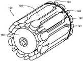
도 1은 본 발명에 따른 팽창성 임플란트의 정면 평면 사시도.
도 2는 도 1의 팽창성 임플란트의 후면 평면 사시도.
도 3은 도 1의 팽창성 임플란트의 정면 입면도.
도 4는 도 1의 팽창성 임플란트의 측단면도.
도 5는 도 1 내지 도 4에 도시된 팽창성 임플란트의 코어 요소의 단면도.
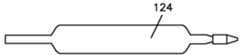
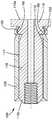
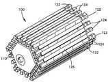
도 6은 도 1 내지 도 4에 도시된 팽창성 임플란트의 슬리브 요소의 단면도.
도 7 및 도 8은 각각 슬리브 요소의 리브 및 스페이서의 평면 입면도.
도 9는 그 내부에 복수의 팽창성 슬리브가 장착되어 있는 삽입 도구의 단면도.
도 10은 본 발명에 따른 팽창성 임플란트의 다른 실시예의 단면도.
도 11은 도 10의 팽창성 임플란트의 단면도.
도 12는 본 발명에 따른 팽창성 임플란트의 다른 실시예의 정면 평면 사시도.
도 13은 도 12의 팽창성 임플란트의 정면 입면도.
도 14는 척추체 내에 삽입된 팽창성 임플란트의 일 실시예의 도면.1 is a front planar perspective view of an expandable implant according to the present invention;
Figure 2 is a rear planar perspective view of the expandable implant of Figure 1;
3 is a front elevational view of the expandable implant of FIG. 1;
Figure 4 is a side cross-sectional view of the expandable implant of Figure 1;
Figure 5 is a cross-sectional view of the core element of the expandable implant shown in Figures 1-4;
Figure 6 is a cross-sectional view of the sleeve element of the expandable implant shown in Figures 1-4;
Figures 7 and 8 are plane elevation views of the ribs and spacers of the sleeve element, respectively.
9 is a sectional view of an insertion tool in which a plurality of inflatable sleeves are mounted.
10 is a sectional view of another embodiment of an expandable implant according to the present invention.
11 is a cross-sectional view of the expandable implant of Fig.
12 is a front planar perspective view of another embodiment of an inflatable implant according to the present invention.
Figure 13 is a front elevational view of the expandable implant of Figure 12;
Figure 14 is an illustration of one embodiment of an inflatable implant inserted within a vertebral body.
본 명세서에 설명된 임플란트, 시스템, 키트, 방법의 실시예 및 예는 본 발명의 범주를 한정하는 것이 아니라, 본 발명의 임플란트, 시스템, 키트 및 방법의 구조, 특징 및 양태의 설명 및 예시로서 이해되어야 한다. 임플란트, 시스템 및 방법의 특징, 구조, 양태 및 단계는 요구되는 바에 따라 또는 적절한 바에 따라 단독으로, 대안적으로 또는 함께 사용될 수 있다. 이하의 설명에 사용되는 특정 용어는 단지 편의 및 설명을 위한 것이고 한정의 방식으로 또는 본질적으로 한정으로서 사용된 것은 아니다. 용어 "우측", "좌측", "하부" 및 "상부"는 참조되는 도면에서의 방향을 나타낸다. 용어 "내향" 및 "외향"은 각각 디바이스의 기하학적 중심을 향해 그리고 기하학적 중심으로부터 이격하는 방향을 칭하고 그 부분을 나타낸다. 용어 "전방", "후방", "상위", "하위" 및 관련 용어 및/구문은 참조되는 인체 내의 바람직한 위치 및 배향을 나타내고 본질적으로 한정을 의미하는 것은 아니다. 용어는 전술된 용어, 그 파생어 및 유사한 의미의 용어를 포함한다.It should be understood that the embodiments and examples of implants, systems, kits, and methods described herein are not intended to limit the scope of the present invention, but rather to illustrate and describe structures, features, and aspects of the present implants, systems, . The features, structures, aspects and steps of the implant, system and method may be used alone, alternatively or in combination, as desired or as appropriate. It is to be understood that the specific terminology used herein is for the purpose of description only and should not be regarded as limiting or in essence limiting. The terms "right "," left ", "lower" and "upper" The terms "inward" and "outward " refer to and refer to directions toward and away from the geometric center of the device, respectively. The terms "forward "," rearward ", "upper "," lower ", and related terms and phrases refer to preferred locations and orientations within the referenced human body and are not meant to be limiting in nature. The terms include the terms mentioned above, derivatives thereof and terms of similar meaning.
본 발명에 따르면, 도 1 내지 도 4를 참조하면, 팽창성 골 증대 임플란트(100)가 제공된다. 임플란트(100)는 바람직하게는 코어 요소(110), 본 실시예에서는 더 바람직하게는 예를 들어 장골, 추골 압박 골절 등의 골간단부의 압박 골절 내부와 같은 골 공동 내에 삽입될 수 있는 실질적으로 원통형 코어 요소를 포함하고, 바람직하게는 이식되는 뼈 또는 다른 조직에 구조적인 지지를 제공할 것이다. 코어 요소(110)는 중실형 또는 삽관형일 수 있고, 종축(112)을 갖는다. 루멘 또는 보어(118)가 코어 요소(110)의 길이로 부분적으로 또는 완전히 아래로 연장될 수 있다. 전체 길이 삽관은 가이드 와이어 상의 위치 내로의 코어 요소 및 임플란트의 배치를 허용하고 용이하게 할 수 있다. 바람직한 실시예에서, 코어 요소(110)는 그 원위 단부(110a)에 총알코형, 둥근형 또는 다른 윤곽의 팁(111)을 포함한다. 코어 요소(110)의 근위 단부(110b)는 바람직하게는 용이한 삽입을 가능하게 하기 위해, 코어 요소(110) 상의 스레딩의 길이, 예를 들어 내부 보어(118)의 근위부(118a)를 따른 스레딩(threading)(112)의 길이와 같은 도구 결합 특징부(115)를 포함한다. 대안적으로 또는 추가적으로, 내부 보어(118)의 근위부(118a)는 스냅 끼워맞춤으로 삽입 도구 상에 돌출부를 수용하도록 치수 설정 및 성형될 수 있고, 또는 코어 요소는 다른 부착 수단에 의해 삽입 도구에 부착될 수 있다. 대안적으로, 도구 결합 특징부(115)는 코어 요소(110)의 외부면(117) 상의 특징부(미도시)와 같은 대안적인 형태를 취할 수 있다.According to the present invention, referring to Figs. 1 to 4, an expandable
임플란트 코어 요소는 바람직하게는 치료될 뼈 또는 조직에 인가되게 되는 생리학적 하중을 지지하기 위해 충분한 구조적 완전성의 재료로부터 형성된다. 코어 요소의 두께, 구성 및 재료는 치료될 뼈 또는 조직 내의 임플란트의 위치, 환자의 크기 및 사용시에 임플란트에 인가될 수 있는 힘에 의존할 것이다. 코어 요소의 적합한 재료는 티타늄, 티타늄 합금, 스테인레스강, 세라믹, 복합 재료, 폴리머, PEEK 및/또는 다른 생체 적합성 재료일 수 있다.The implant core element is preferably formed from a material of sufficient structural integrity to support a physiological load to be applied to the bone or tissue to be treated. The thickness, configuration and material of the core element will depend on the location of the implant in the bone or tissue to be treated, the size of the patient, and the force that can be applied to the implant at the time of use. Suitable materials for the core element may be titanium, titanium alloys, stainless steel, ceramics, composites, polymers, PEEK and / or other biocompatible materials.
임플란트(100)는 바람직하게는 사용시에 임플란트(100)가 임플란트 코어 요소(110) 주위에 적층되거나 중첩되는 슬리브 요소(120)를 순차적으로 삽입함으로써 바람직하게는 반경방향으로 팽창 가능하도록 하는 하나 이상의 슬리브 요소(120)를 포함한다. 바람직하게는, 슬리브 요소는 반경방향으로 팽창 가능하다. 도시된 바와 같이, 제 1 슬리브(120a)는 이하에 더 상세히 설명되는 바와 같이 삽입기 도구(200)와 같은 삽입 도구를 사용하여 코어 요소(110) 상에서 활주될 수 있다. 제 2 슬리브(120b)는 이전에 삽입된 슬리브 요소(120a)와 코어 요소(110) 사이에서 코어 요소(110) 상에서 활주될 수 있어 제 2 슬리브(120b)가 코어 요소(110)와 제 1 슬리브(120a) 사이에 삽입될 때 제 1 슬리브(120a)가 반경방향으로 팽창되게 된다. 제 3 슬리브 요소(120c)가 제 2 슬리브 요소(120b)와 코어 요소(110) 사이에서 코어 요소(110) 상에서 활주할 때, 제 1 및 제 2 슬리브(120a, 120b)가 반경방향으로 팽창된다. 임의의 수의 슬리브 요소(120)가 임플란트(100)의 원하는 최종 형상 및 크기를 제공하도록 선택될 수 있다. 그 결과, 임플란트(100)는 바람직하게는 최소 침습성 절차를 이용하여 경피적 접근 경로를 통해 삽입될 수 있고, 이는 뼈 또는 조직 내의 공동 또는 캐비티를 충전하도록 더 큰 임플란트 체적으로의 증분적인 팽창을 경험하고, 바람직하게는 뼈 또는 조직을 가로질러 인가된 하중을 지지하고, 예를 들어 스크류 또는 다른 체결구와 같은 다른 하드웨어 또는 임플란트를 위한 보충 고정구로서 작용하고, 뿐만 아니라 몇몇 경우에 예를 들어 붕괴된 척추체와 같은 붕괴된 뼈 또는 조직의 원하는 높이 및 형상을 복원한다. 임플란트의 팽창은 해면골을 치밀화할 수 있고, 피질골을 이동시킴으로써 붕괴된 뼈의 높이 및 형상을 복원할 수 있다.The
코어 요소(110)의 구조 및 구성은 팽창성 임플란트(100)를 형성하기 위해 코어 요소(110)와 슬리브 요소(120) 사이의 상호 작용 및 슬리브 요소와 같이 이하에 더 상세히 설명될 것이다. 도 1 내지 도 5의 실시예의 코어 요소(118)는 실질적으로 원통형 형상이고 직경 및 길이를 갖는 것으로서 도시되고 설명되어 있지만, 코어 요소의 단면 형상은 비원형일 수도 있고 예를 들어 정사각형, 6각형, 8각형, 사다리꼴 또는 다른 다각형 형상과 같은 평평한 표면 또는 측면을 제공하는 단면 형상을 가질 수도 있다는 것이 이해되어야 한다. 이들 및 다른 형상은 코어 요소를 위해 사용하기 위해 고려된다. 용어 "직경"은 비원형 단면을 참조하여 사용될 때 주어진 문맥에서 적절할 수 있는 바와 같이 단면 크기, 폭 및 두께를 칭한다.The structure and configuration of the
코어 요소는 그 길이의 상당부를 따라 제 1 직경(116) 또는 단면 형상을 가질 수 있다. 코어 요소의 근위 단부(110b)는 코어 요소 상에 슬리브 요소의 활주를 용이하게 하기 위한 경사진, 모따기된 또는 무딘 에지(114)를 가질 수 있다. 코어 요소(110)의 원위 단부(110a)는 슬리브 요소(120) 중 하나 이상을 위한 정지부(111a)를 형성하도록 확장될 수 있다. 코어 요소(110)는 그 외부면(117) 상에 하나 이상의 리세스(119)를 구비할 수 있다. 리세스(119)는 이하에 더 상세히 설명되는 바와 같이 코어 요소(110)에 슬리브 요소(120)를 결합하고 고정하는 것을 허용하고 용이하게 한다. 리세스(119)는 코어 요소의 외부면(117) 주위에 원주방향으로 또는 코어 요소의 외부면(117)의 원주를 따른 선택된 위치에 제공될 수 있다. 리세스(119)는 도 5에 도시된 바와 같이 원위부 상에, 또는 대안적으로 또는 부가적으로 코어 요소(110)의 근위 또는 중간부에 제공될 수 있다. 리세스(119)는 코어 요소 상의 슬리브 요소의 결합 및 고정을 허용하고 용이하게 하는 다른 특징 및 구성을 포함할 수 있다.The core element may have a
코어 요소는 코어 요소 주위에 원주방향으로 연장하는 하나 이상의 팽창성 밴드(136)(미도시)를 추가로 포함할 수 있다. 팽창성 밴드(136)는 코어 요소(110)의 근위, 중간 및/또는 원위부 주위로 연장될 수 있다. 팽창성 밴드(136)는 슬리브 요소가 코어 요소(110) 상의 위치로 활주될 때 슬리브 요소(120)에 대해 반경방향 압축력을 제공하는 것을 지원할 수 있다. 슬리브 요소(120)는 바람직하게는 팽창성 밴드(136) 아래에 위치될 것이다. 게다가, 코어 요소는 슬리브 요소들이 코어 요소 상으로 이동할 때 슬리브 요소의 위치 설정 및 배향을 지원하고 용이하게 하기 위한 하나 이상의 종방향 홈(미도시)을 포함할 수 있다.The core element may further include at least one inflatable band 136 (not shown) extending circumferentially around the core element. The inflatable band 136 may extend around the proximal, middle, and / or distal portion of the
코어 요소(110)는 바람직하게는 예를 들어 천공부, 캐뉼러 또는 소형 절개부를 통해서와 같은 최소 침습성 개구를 통해 뼈 내로의 삽입을 허용하고 용이하게 하도록 치수 설정 및 성형된다. 일 실시예에서, 코어 요소의 외경은 대략 6 mm일 수 있고, 원위 팁(110a)은 대략 8 mm의 직경이다. 코어 요소의 다른 직경 및 구성이 고려된다. 코어 요소(110a)는 다양한 크기, 예를 들어 치료되도록 의도된 상이한 뼈에 적합한 복수의 상이한 길이 및/또는 직경, 및/또는 단면 형상으로 제공될 수 있다. 일 실시예에서, 코어 요소는 대략 2 cm의 길이를 가질 수 있다. 무수히 많은 코어 요소가 상이한 길이로 제공되어 치료될 뼈에 적합한 임플란트(100)가 키트에 제공된 구성 요소를 거쳐 조립될 수 있게 되고, 또는 적절한 크기의 임플란트를 형성하기 위해 시스템의 부분으로서 수술실에서 조립될 수 있게 된다. 상이한 크기의 코어 요소가 예를 들어 2 mm와 같은 미리 선택된 증분으로 증가하는 길이로 제공될 수 있어, 코어 요소는 2 cm, 2.2 cm, 2.4 cm, 2.6 cm 등의 길이가 될 수 있다. 이 방식으로, 적절한 길이의 임플란트가 치료될 뼈에 대해 선택될 수 있다. 코어 요소의 직경 또는 단면 크기는 또한 예를 들어 6 mm, 8 mm, 10 mm 등의 직경과 같은 미리 선택된 증분으로 증가하는 크기로 제공될 수 있다.The
도 1 내지 도 4 및 도 6 내지 도 11을 참조하면, 슬리브 요소(120)는 바람직하게는 팽창 가능하다. 슬리브 요소(120)는 바람직하게는 중공 내부와 연통하는 개구를 원위 단부에 갖는다. 슬리브 요소는 또한 바람직하게는 중공 내부와 연통하는 개구를 근위 단부에 가져, 슬리브 요소가 바람직하게는 길이, 내경(DI), 외피 두께(t) 및 외경(DO)을 갖는 중공 튜브가 되게 한다. 슬리브 요소의 근위 단부는 개구를 갖지 않을 수도 있고, 폐쇄되고, 부분적으로 폐쇄되고, 부분적으로 개방될 수 있고 그리고/또는 근위 개구를 부분적으로 차단하는 립, 플랜지 또는 숄더를 갖고 형성될 수 있고, 슬리브가 코어 요소 상에서 너무 멀리 삽입되는 것을 방지하는 정지 부재를 형성할 수 있다. 슬리브 요소 및 코어 요소는 바람직하게는 코어 요소(110)의 외부면(117)의 직경 또는 단면이 슬리브 부재의 내경(DI) 또는 단면과 대략 동일한 크기이거나 약간 커서 바람직하게는 슬리브 요소가 코어 요소 상에 끼워지며 약간 팽창되도록 구성된다. 이 방식으로, 압축 반경방향 힘이 슬리브 요소에 의해 코어 요소에 인가되어 코어 요소에 슬리브 요소를 고정하는 것을 지원한다.Referring to Figs. 1-4 and 6-11, the
도 1 내지 도 4 및 도 6 내지 도 11을 참조하면, 슬리브 요소는 복수의 리브(122) 및 스페이서(124)를 포함할 수 있다. 리브(122) 및 스페이서(124)는 바람직하게는 이들을 가로질러 인가된 생리학적 하중을 지지하기 위해 충분한 구조적 완전성 및 강도의 임의의 생체 적합성 재료로 형성된다. 이러한 재료는 예를 들어 스테인레스강, 티타늄, 티타늄 합금, 금속, 금속 합금, 세라믹, 폴리머, PEEK, 복합 재료, 타가 이식 또는 자가 이식 뼈를 포함할 수 있다. 리브(122) 및 스페이서(124)는 금속, 폴리머 또는 탄성 중합 재료로 형성된 팽창성 멤브레인(126) 또는 메시에 의해 상호 연결될 수 있다. 팽창성 멤브레인(126)은 리브(122) 및 스페이서(124)에 부착되어 반경방향 내향 압축력을 인가한다. 멤브레인(126)은 리브(122) 또는 스페이서(124)의 임의의 표면에 부착될 수 있거나 리브(122) 및 스페이서(124)의 본체를 통과할 수 있다. 멤브레인(126)은 균일한 요소일 수 있거나, 리브(122)와 스페이서(124) 사이에 맞물리는 분할부로 구성될 수 있다. 멤브레인(126)은 뼈 내의 공동을 가장 양호하게 충전하고 하중을 지지하기 위해 리브(122)와 스페이서(124) 사이의 균일한 또는 가변 팽창을 허용할 수 있다. 하나 이상의 팽창성 멤브레인(126)은 슬리브 요소(120)를 구비할 수 있다. 팽창성 멤브레인(126)은 팽창성 밴드(136)에 추가하여 또는 대안적으로 그 대신에 제공될 수 있다.1 through 4 and 6 through 11, the sleeve element may include a plurality of
슬리브 요소(120)는 각각의 리브와 스페이서 사이로 연장하는 가요성 지주에 의해 상호 연결된 리브 및 스페이서를 또한 포함할 수 있다. 가요성 지주는 리브와 스페이서 사이의 팽창을 허용한다. 슬리브 요소는 리브, 스페이서 및 지주의 단일편의 일체형 디자인일 수 있고, 단일편의 재료로부터 가공될 수 있다. 가요성 지주는 각각의 리브와 스페이서 사이의 제어된 팽창을 허용하여 불균일한 팽창을 허용하고 적어도 하나의 평평한 표면 또는 측면을 가질 수 있는 비원형 단면 형상을 형성할 수 있다. 평평한 측면 또는 표면을 갖는 것은 예를 들어 평평한 표면이 추골의 종판에 평행하도록 배열되어 압력을 인가하여 추골 종판을 재배향하고, 팽창시키고, 지지하는 추골을 팽창시키는 것과 같은 특정 절차에 유리할 수 있다.
리브(122)는 도 7에 도시된 바와 같은 개뼈 형상 또는 임의의 다른 적합한 형상을 가질 수 있다. 스페이서(124)는 도 8에 도시된 형상 또는 임의의 다른 적합한 형상을 가질 수도 있다. 리브 및 스페이서는 도시된 바와 같이 서로 대응하고 상보적인 형상, 또는 비대응적인, 비상보적인 형상을 가질 수도 있다. 슬리브 요소는 바람직하게는 슬리브가 가요성 및 팽창 가능하게 되는 것을 허용하기 위해 무수히 많은 리브(122) 및 스페이서(124)로 형성된다. 슬리브는 또한 실질적으로 동일한 크기 및 형상 또는 동일한 형상이지만 상이한 크기를 각각 갖는 리브 또는 스페이서만으로 형성될 수 있다.The
슬리브 요소(120)는 대략 1 mm 두께일 수 있지만, 다른 두께가 고려된다. 슬리브 요소, 리브 및 스페이서의 두께는 비교적 균일한 두께를 가질 수 있고, 비교적 평평할 수 있다. 대안적으로, 슬리브, 리브 및 스페이서는 비교적 불균일한 두께를 가질 수도 있고, 예를 들어 웨지 형상일 수 있다. 대안적으로 또는 추가적으로, 슬리브, 리브 또는 스페이서의 외부면은 만곡될 수 있을 뿐만 아니라 내부면일 수도 있다. 슬리브 요소의 외부면(128)은 리세스(139)를 가질 수 있고, 반면 내부면(129)은 돌출부(138)를 가질 수도 있다. 슬리브 요소(120) 상의 돌출부(138)는 바람직하게는 코어 요소(110) 내에 형성된 리세스(119) 또는 인접한 슬리브 요소(120) 내에 형성된 리세스(139)와 결합되고 상호 체결될 것이다. 돌출부(138) 및 리세스(139)는 리브(122), 스페이서(124) 또는 양자 모두 상에 형성될 수 있다. 돌출부(138) 및 리세스(139)는 리브 및 스페이서의 폭 또는 전체 폭을 가로질러 단지 부분적으로만 연장될 수 있다. 돌출부(138)는 바람직하게는 리세스(119) 또는 리세스(139) 내에 스냅 끼워맞춤될 수 있다. 이 방식으로, 팽창성 슬리브 요소가 코어 요소 및 이전의 슬리브 요소에 결합되어 뼈 또는 다른 조직 내에 경험되는 하중을 지지하도록 구조적으로 일체화된 임플란트를 제공한다.
리세스(119, 130) 및 대응 돌출부(138)는 슬리브가 코어 요소 상에서 이동할 때 돌출부(138)가 리세스(119, 139) 내로 활주하는 것을 용이하게 하기 위해 도 4 내지 도 6에 도시된 바와 같이 삼각형으로 성형될 수 있다. 리세스(119, 139)의 원위부 또는 벽(146) 및 돌출부(138) 상의 벽(147)의 형상은 바람직하게는 슬리브가 코어 요소 또는 이전에 배치된 슬리브 요소를 지나 연장하는 것을 방지하기 위한 정지 메커니즘(145)을 형성한다. 코어 요소 또는 이전의 슬리브 요소로의 슬리브 요소의 체결을 용이하게 하기 위한 특징부가 리세스(119, 139) 및 돌출부(138)에 제공될 수 있다. 코어 요소 및 슬리브 요소 상의 돌출부 및 리세스는 돌출부가 코어 요소 및/또는 슬리브 요소의 외부면 상에 형성되고 리세스가 슬리브 요소의 내부면 상에 형성되도록 반전될 수 있다. 리세스 및 돌출부는 도 4에 도시된 바와 같이 코어 요소 및/또는 슬리브 요소의 길이에 실질적으로 수직인 벽을 갖고 삼각형으로 성형될 수 있고, 또는 다른 형상이 이용될 수 있다.The
대안적으로 또는 추가적으로, 다른 특징부가 코어 요소 및 슬리브 요소 상에 제공되어 슬리브 요소를 서로에 대해 또는 코어 요소에 결합할 수 있다. 예를 들어, 도 10에 도시된 바와 같이, 슬리브 및 코어 요소는 리세스(119, 139)의 바로 원위측에 바람직하게는 둥글어진 범프(bump)(150)와, 슬리브를 코어 요소에 결합하는 것을 지원하기 위해 범프를 수용하도록 돌출부(138)의 바로 원위측에 바람직하게는 둥글어진 딤플(dimple)(152)을 구비할 수 있다.Alternatively or additionally, other features may be provided on the core element and the sleeve element to couple the sleeve elements to one another or to the core element. For example, as shown in FIG. 10, the sleeve and core element may include a
임플란트(100)는 삽입 도구를 거쳐 삽입될 수 있다. 도 9에 가장 양호하게 도시된 바와 같이, 삽입 도구(200)의 바람직한 실시예가 도시된다. 삽입 도구(200)는 바람직하게는 임플란트(100)와 함께 사용하기 위해 구성되고, 최소 침습성 수술 방법을 특히 적응될 수 있다. 도구(200)는 중공 배럴(210)과, 바람직하게는 배럴(210) 내에 바람직하게 반경방향으로 중심 설정된 로드(220)를 포함한다. 로드(220)는 예를 들어 코어 요소(110) 상의 도구 결합 특징부(115)와 정합할 수 있는 외부 스레딩 또는 스타 드라이브(star drive)와 같은 코어 요소 결합 특징부(225)를 그 원위 단부에 포함한다. 슬리브 요소(120)는 바람직하게는 단부-대-단부 방식으로 로드(220)를 따라 수용되고, 배럴(210)을 통해 그리고 로드(210)를 따라 전진될 수 있다. 일 실시예에서, 도구(200)는 뼈, 바람직하게는 붕괴된 척추체 내에 코어 요소(110)를 지향하여 배치하는데 사용된다. 슬리브(120)는 예를 들어 플런징(plunging) 메커니즘(230)에 의해 전술된 바와 같이 배럴(210)을 통해 로드(220)를 따라 이식된 코어 요소(110) 상으로 통과된다. 슬리브(120)의 내부, 바람직하게는 슬리브(120)의 원위 단부의 내부는 코어 요소(110)의 원위 단부 상에 스냅 결합하여 슬리브(120)를 코어 요소(110)에 고정하거나 슬리브(120a)를 슬리브(120b)에 고정하는 등을 위해 구성될 수 있다. 의사가 팽창성 임플란트(100)의 원하는 반경방향 체적 또는 크기를 얻을 때, 의사는 추가의 슬리브(120)를 전진하는 것을 중단하고 결합 특징부(115)로부터 결합 특징부(225)를 해제한다.The
도 1, 도 4 및 도 6을 참조하면, 바람직한 실시예에서, 슬리브(120)는 바람직하게는 새로운 슬리브(120)를 수용하도록 임플란트 상에 미리 위치된 슬리브 또는 슬리브들(120)을 반경방향으로 팽창시키기 위해, 다른 슬리브(120)가 코어 요소(110) 상에 미리 위치된 후에 슬리브(120)가 코어 요소(110) 상에 삽입되거나 압박되는 것을 허용하거나 용이하게 하는 경사진 노즈(121)를 이들의 원위 단부에 포함한다. 슬리브(120)의 원위 단부 상의 경사진 노즈(121)는 도시된 형상에 한정되는 것은 아니고, 슬리브(120)는 거의 임의의 방식으로 배열되고 성형될 수 있고, 또는 로드(220)는 추가의 슬리브(120)가 코어 요소의 원위 단부 상에 삽입될 때 슬리브(120)가 반경방향으로 팽창되는 것을 허용하도록 거의 임의의 방식으로 구성될 수 있다. 예를 들어, 각각의 슬리브(120)는 다른 슬리브(120) 아래로 그리고 코어 요소(110) 상으로 활주하는 하나의 슬리브(120)를 수용하도록 경사진 노즈(121)에 대향하여 각형성되는 램프(135)를 포함할 수 있다. 슬리브(120) 상의 경사진 노즈(121)는 또한 이러한 팽창성 밴드(136)가 코어 요소 상에 제공되면 팽창성 밴드(136) 아래로 슬리브가 활주하는 것을 용이하게 할 수 있다. 코어 요소 내의 종방향 홈의 존재는 또한 코어 요소 및 서로에 대한 슬리브 요소의 활주 및 정렬을 용이하게 할 수 있고, 종방향 홈은 또한 팽창성 밴드(136) 아래로 슬리브가 활주하는 것을 지원하고 용이하게 할 수 있다.Referring to Figures 1, 4 and 6, in a preferred embodiment, the
슬리브(120)는 삽입 도구 내에 미리 로딩되어 제공될 수 있다. 대안적으로, 슬리브는 예를 들어 의사 또는 직원에 의해 수술실에서 환자 내로의 삽입 직전에 또는 절차 직전에 선택되어 로딩될 수 있다. 슬리브는 다양한 길이 및 두께로 공급될 수 있다. 일 예시적인 실시예에서, 슬리브는 대략 18 mm 길이, 대략 5.5 mm의 내경 및 대략 1 mm의 외피 두께(t)일 수 있어 각각의 추가의 슬리브가 대략 2 mm 만큼 팽창성 임플란트(100)의 두께, 높이, 직경 또는 단면 크기를 증가시키게 된다. 예를 들어, 대략 6 mm의 코어 요소 직경을 갖는 도 1의 팽창성 임플란트 및 대략 1 mm 두께의 3개의 팽창성 슬리브가 슬리브들 사이의 간격 및 간극을 고려할 때 대략 12 내지 13 mm의 직경을 가질 것이다. 슬리브는 또한 상이한 길이로 제공될 수 있고, 상이한 길이의 무수히 많은 슬리브가 상이한 길이 및 높이의 팽창성 임플란트를 형성하기 위해 키트 또는 시스템에 제공될 수 있다.The
삽입 도구는 비팽창 상태에서 동일한 크기(길이 및 직경)의 슬리브를 생성하는 리브 및 스페이서의 동일한 크기 및 구성을 모두 갖는 다수의 슬리브로 로딩될 수 있다. 동일한 크기의 슬리브가 코어 상에 삽입될 때, 더 이전에 배치된 슬리브가 팽창되어 팽창된 상태에서 적층된 각각의 슬리브가 상이한 직경(단면 크기)일 수 있게 된다. 팽창성 임플란트에서, 최초 배치된 팽창성 슬리브는 가장 멀리 반경방향으로 팽창될 수 있고, 리브와 스페이서 사이의 간격은 제 1 슬리브 부재 상에서 더 클 수 있다. 즉, 코어 요소 상에 삽입 후에 리브와 스페이서 사이의 간격은 적층된 슬리브의 레벨에 의해 변경될 수 있다. 도 1의 실시예에서, 각각의 리브와 스페이서 사이의 간극 또는 공간은 제 2 열에서 약 0.45 mm이고, 제 3 열에서 약 0.58 mm일 수 있다. 대안적으로, 상이한 크기의 슬리브(길이 및/또는 직경)가 삽입 도구 내에 로딩될 수 있다. 상이한 길이의 슬리브가 팽창성 임플란트를 구성하는데 사용되면, 슬리브는 이들이 적층될 때 원위 단부가 테이퍼진 또는 무딘 원위 단부를 제공하도록 구성될 수 있다. 예를 들어, 슬리브는 이후에 삽입된 각각의 슬리브 상의 돌출부를 넘는 원위 단부가 이전에 삽입된 각각의 슬리브와 동일하거나 긴 길이가 되도록 리세스(139) 및 돌출부(138)가 구성되도록 형성될 수 있다.The insertion tool can be loaded into multiple sleeves having both the same size and configuration of ribs and spacers producing sleeves of equal size (length and diameter) in the unexpanded state. When a sleeve of the same size is inserted on the core, the previously disposed sleeve is inflated so that each sleeve laminated in the expanded state can be of different diameter (cross-sectional size). In an inflatable implant, the initially deployed inflatable sleeve can be furthest radially inflated, and the spacing between the rib and the spacer can be larger on the first sleeve member. That is, the spacing between the ribs and spacers after insertion on the core element can be varied by the level of the stacked sleeves. In the embodiment of Figure 1, the clearance or space between each rib and spacer may be about 0.45 mm in the second row and about 0.58 mm in the third row. Alternatively, sleeves of different sizes (length and / or diameter) may be loaded into the insertion tool. If different lengths of sleeve are used to construct the expandable implant, the sleeve may be configured such that the distal end provides a tapered or blunt distal end when they are laminated. For example, the sleeve may be formed such that
특정 뼈 또는 특정 조건에서 비원통형 형상의 임플란트가 제공될 수 있는 것이 유리할 수 있다. 예를 들어, 비교적 평평한 표면을 갖는 팽창성 임플란트를 제공하는 것이 유리할 수 있다. 이러한 평평한 표면은 평평한 표면 또는 표면들이 척추체의 하위 또는 상위 종판을 향해 지향될 수 있는 척추체에서 유리할 수 있다. 이러한 형상은 마찬가지로 장골 및 다른 뼈에서 유리할 수 있다. 고려되는 비원통형 임플란트 형상은 적어도 하나의 비교적 평평한 측면 또는 표면을 제공할 수 있는 6각형, 8각형, 정사각형, 사다리꼴, 다른 다각형 형상 또는 비대칭 형상을 포함한다. 도 10 내지 도 11은 정사각형 형상을 형성하는 팽창성 임플란트를 도시하고, 도 12 내지 도 13은 8개의 비교적 평평한 측면을 갖는 6각형 형상 임플란트를 도시한다. 도 12 내지 도 13의 팽창성 임플란트(100")는 측면 에지 상에 리브(122)를 갖는 6각형의 각각의 측면에 2개의 스페이서(124)를 갖고 형성된다. 탄성 멤브레인(126)은 리브와 스페이서를 함께 연결하고 슬리브의 팽창을 허용한다.It may be advantageous that an implant of a non-cylindrical shape can be provided at a particular bone or under certain conditions. For example, it may be advantageous to provide an expandable implant having a relatively flat surface. This flat surface may be advantageous in a vertebra where a flat surface or surfaces can be directed towards the lower or upper endplate of the vertebral body. This shape can likewise be beneficial in the iliac and other bones. The non-cylindrical implant configuration contemplated includes hexagonal, octagonal, square, trapezoidal, other polygonal, or asymmetric shapes that may provide at least one relatively flat side or surface. Figures 10-11 illustrate an expandable implant that forms a square shape, and Figures 12-13 illustrate a hexagonal shaped implant with eight relatively flat sides. The
비원통형 임플란트는 적어도 하나의 실질적으로 평평한 측면 또는 표면을 갖는 비원통형 형상 코어 요소로 구성되거나 조립될 수 있다. 비팽창된 원통형 형상의 슬리브가 비원통형 형상의 코어 요소 상에 배치될 수 있다. 리브와 스페이서 사이의 팽창은 슬리브가 팽창되어 비원통형 형상으로 변화됨에 따라 변경될 수 있다. 리브와 스페이서 사이의 가요성 지주는 몇몇 위치에서 다른 것들보다 더 많이 팽창되게 되고, 또는 몇몇 리브와 스페이서 사이의 팽창성 멤브레인 또는 팽창성 밴드는 다른 것들보다 더 많이 팽창되게 된다. 대안적으로, 슬리브는 리브와 스페이서 사이의 간격이 미리 변경되어 슬리브가 원하는 비원통형 형상으로 형성되는 비원통형 형상으로 제공될 수 있다. 대안적으로, 슬리브 요소는 슬리브의 전체 원주 주위로 연장되지 않는 리브 및 스페이서로 형성될 수 있다. 슬리브가 코어 요소 상에 배치될 때 비대칭 임플란트가 생성될 수 있다. 대안적으로 또는 추가적으로, 불균일한 두께 리브 및 스페이서 및/또는 리브 및 스페이서 상의 만곡된 외부면 및 내부면이 팽창성 임플란트의 원하는 형상 및 크기를 생성하는데 사용될 수 있다.The non-cylindrical implant may be constructed or assembled with a non-cylindrical shaped core element having at least one substantially flat side or surface. An unexpanded cylindrical shaped sleeve may be disposed on the non-cylindrical shaped core element. The expansion between the rib and the spacer may change as the sleeve is expanded and transformed into a non-cylindrical shape. The flexible struts between the ribs and the spacers are inflated more than others at some locations or the inflating membrane or inflatable band between some ribs and spacers is inflated more than others. Alternatively, the sleeve may be provided in a non-cylindrical shape in which the spacing between the rib and the spacer is previously modified such that the sleeve is formed into the desired non-cylindrical shape. Alternatively, the sleeve element may be formed of ribs and spacers that do not extend around the entire circumference of the sleeve. Asymmetric implants can be created when the sleeve is placed on the core element. Alternatively or additionally, uneven thickness ribs and spacers and / or curved outer and inner surfaces on the ribs and spacers may be used to create the desired shape and size of the expandable implant.
사용시에, 통로가 치료될 뼈에 생성되고, 통로는 임플란트가 위치되는 뼈 내에 형성될 수 있다. 드릴 또는 투관침이 뼈 내에 통로를 생성하는데 사용될 수 있다. 선택사양으로, 캐비티는 뼈, 바람직하게는 해면골을 제거하거나 치밀화함으로써 뼈 내에 형성될 수 있다. 벌룬 팽창성 카테터는 캐비티를 생성하는데 사용될 수 있고, 또는 다른 도구가 뼈를 치밀화하거나 뼈를 제거함으로써 캐비티를 생성하는데 사용될 수 있다. 대안적으로, 단지 통로만이 확장된 캐비티를 형성하지 않고 뼈 내에 형성될 수 있다. 접근 튜브 또는 캐뉼러는 연조직을 통해 아래로 삽입될 수 있다. 접근 튜브는 또한 뼈 내의 통로 내에 삽입될 수 있다. 접근 튜브는 바람직하게는 접근 튜브 내에 제공된 중공 보어로 삽입 도구 및 코어 요소를 하강하는 것을 허용하기 위한 충분한 내경(단면)을 갖는다.In use, a passageway is created in the bone to be treated, and a passageway may be formed in the bone where the implant is located. A drill or trocar can be used to create a passage in the bone. Optionally, the cavity can be formed in the bone by removing or densifying the bone, preferably the cancellous bone. Balloon inflatable catheters can be used to create cavities, or other tools can be used to create cavities by densifying bones or removing bones. Alternatively, only passages may be formed in the bone without forming an expanded cavity. The access tube or cannula may be inserted down through the soft tissue. The access tube may also be inserted into the passage in the bone. The access tube preferably has an inner diameter (cross-section) sufficient to allow the insertion tool and the core element to descend into a hollow bore provided in the access tube.
코어 요소는 바람직하게는 삽입 도구의 로드에 부착(나사 결합)된다. 삽입 도구는 코어 요소로의 로드의 부착 전 또는 후에 슬리브로 사전 로딩될 수 있다. 삽입 도구 및 코어 요소 조립체는 함께 뼈 내의 통로 또는 캐비티 내의 적소에 배치된 접근 튜브 및 코어 요소를 아래로 삽입될 수 있다.The core element is preferably attached (screwed) to the rod of the insertion tool. The insertion tool can be preloaded into the sleeve either before or after attachment of the rod to the core element. The insertion tool and the core element assembly together can be inserted down the access tube and core element located in the passageway or cavity in the bone.
플런저 메커니즘은 삽입 도구의 로드 및 배럴이 뼈 내에 정지 유지되는 동안 코어 요소 상에 제 1 슬리브(120a)를 이동시키도록 활성화된다. 임플란트의 추가의 팽창이 요구되면, 플런저 메커니즘은 더 큰 직경 또는 단면 크기를 갖는 임플란트를 제공하기 위해 코어 요소 상에 그리고 제 1 슬리브(120a) 아래에 제 2 슬리브(120b)를 이동시키도록 작동된다. 임플란트의 또 다른 팽창이 요구되면, 플런저 메커니즘이 재차 작동되어 코어 요소의 상부 및 제 2 슬리브(120b) 아래에 제 3 슬리브(120c)를 배치하여 증가된 직경 또는 단면 크기(높이 및/또는 두께)의 더 큰 크기의 임플란트를 제공한다. 코어 요소 상에 추가의 슬리브(120)를 배치하는 작업은 임플란트가 원하는 크기가 될 때까지 계속된다. 후속의 슬리브가 삽입될 때, 더 먼저 삽입된 슬리브가 팽창한다. 슬리브 및 따라서 임플란트의 팽창은 뼈 또는 다른 조직 또는 공간 내에 생성된 캐비티를 충전할 수 있다. 슬리브 및 임플란트의 팽창은 원하는 치료에 따라 뼈, 바람직하게는 해면골을 추가로 치밀화할 수 있다. 임플란트의 팽창은 또한 뼈 및/또는 조직을 이동시킬 수 있다. 일 바람직한 실시예에서, 임플란트의 팽창은 그 원하는 크기, 형상 및 위치로 뼈를 복원하거나 배치하기 위해 해면골을 치밀화하고 피질골을 이동시킬 수 있다. 예를 들어, 임플란트는 척추체 내의 해면골을 이동시키거나 치밀화할 수 있고, 종판의 높이 및 각도를 조정하기 위해 추체 종판을 더 이동시킬 수 있다.The plunger mechanism is activated to move the
임플란트가 원하는 크기로 팽창된 후, 로드는 임플란트로부터 탈착된다. 선택사양으로, 단부 캡(180)은 임플란트(100)의 근위 단부(110b)에 결합될 수 있다. 단부 캡(180)은 코어 요소의 보어(118a) 내로 연장하는 돌출부(185)를 가질 수 있다. 돌출부(185)는 코어 요소 내의 스레딩에 결합하는 스레딩을 가질 수 있고, 또는 플랜지(미도시) 및 숄더(미도시)에 의해 보어(118a) 내에 간단히 스냅 끼워맞춰질 수 있다. 임플란트(100)에 단부 캡(180)을 연결하는 다른 방식이 고려된다. 상이한 크기의 단부 캡(180)이 제공되어 단부 캡은 코어 요소를 너머 반경방향으로 연장될 수 있고 슬리브가 원위측으로 이동하는 것을 방지하게 될 수 있다.After the implant is inflated to the desired size, the rod is removed from the implant. Optionally, the
코어 요소 및 삽입 도구가 접근 튜브를 아래로 삽입되는 것으로서 설명되었지만, 삽입 도구 및 코어 부재는 조직 견인기 또는 캐뉼러 없이 피부를 통해 직접 삽입될 수 있고, 또는 피부를 직접적으로 천공할 수 있고, 추가적으로 또는 대안적으로 가이드 와이어 상에 적소에 삽입될 수 있다는 것이 이해될 수 있을 것이다.Although the core element and the insertion tool have been described as being inserted down the access tube, the insertion tool and core member may be inserted directly through the skin without a tissue retractor or cannula, or may be directly pierced with the skin, Or alternatively may be inserted in place on the guidewire.
일단 임플란트가 위치되면, 임플란트는 천공되고 임의의 방향으로부터 테이퍼져서 스크류, 네일, k-와이어 또는 다른 체결구를 통과하여 다른 하드웨어로 고정을 보충할 수 있다. 예를 들어, 척추체 내에 배치되면, 슬리브 임플란트는 척추판을 적소에 고정하기 위해 추골 내에 삽입된 하나 이상의 스크류를 수용하도록 천공 및 태핑된 슬리브를 가짐으로써 플레이트 고정을 지원할 수 있다. 판 고정을 보충하기 위한 슬리브 임플란트를 사용하는 동일한 절차가 장골, 연조직 또는 비의료용 용례에서 사용될 수 있다.Once the implant is positioned, the implant can be pierced and tapered from any direction, passing through screws, nails, k-wires, or other fasteners and replenishing fixation with other hardware. For example, if placed in the vertebral body, the sleeve implant may support plate fixation by having perforated and tapped sleeves to accommodate one or more screws inserted in the vertebrae to secure the vertebral plate in place. The same procedure using sleeve implants to supplement plate fixation can be used in iliac, soft tissue or non-medical applications.
더욱이, 임플란트(100)가 뼈 내에 배치된 후에, 뼈 시멘트, 뼈 조각 또는 다른 생물학적 재료 또는 폴리머 재료가 뼈 내의 캐비티 또는 통로 내에 삽입될 수 있다. 추가적으로 또는 대안적으로, 예를 들어 뼈로 형성된 플러그가 임플란트(100) 후방에 삽입될 수 있다. 뼈 시멘트 또는 다른 생물학적 또는 폴리머 재료가 전술된 보충 고정과 함께 사용될 수 있고, 보충 고정 전, 후 또는 중에 삽입될 수 있다.Moreover, after the
본 발명에 의해 제공되는 임플란트(100) 및 바람직한 최소 침습성 수술 방법은 임플란트(100)가 기하학적으로 팽창하기 때문에 의사가 임플란트(100)의 원래 위치 및 최종 팽창 기하학적 형상을 제어하는 것을 가능하게 한다.The
일 실시예에서, 코어 요소는 대략 4 mm 내지 대략 8 mm의 직경 또는 높이 및 대략 1.5 cm 내지 대략 2.5 cm의 길이를 갖고, 슬리브 요소는 대략 4 mm 내지 대략 8 mm의 내경 또는 높이, 대략 1.5 cm 내지 대략 2.5 cm의 길이 및 대략 1 mm 내지 대략 2 mm의 두께를 갖는다. 물론, 상이한 크기의 임플란트가 예를 들어 치료될 뼈를 포함하는 용례에 따른 적절하고 바람직한 것으로 인식됨에 따라, 상이한 크기의 코어 요소 및 슬리브가 제공될 수 있다. 당 기술 분야의 숙련자는 상이한 뼈, 치료되는 골절 및 조건에 적절한 임플란트, 코어 요소 및 슬리브의 크기를 인지하고 이해할 수 있을 것이다.In one embodiment, the core element has a diameter or height of about 4 mm to about 8 mm and a length of about 1.5 cm to about 2.5 cm, and the sleeve element has an inner diameter or height of about 4 mm to about 8 mm, To about 2.5 cm in length and about 1 mm to about 2 mm in thickness. Of course, different sized core elements and sleeves may be provided, as different sized implants are perceived to be appropriate and preferred according to the application including, for example, bone to be treated. Those skilled in the art will recognize and appreciate the size of implants, core elements and sleeves suitable for different bones, fractures treated and conditions.
광범위한 본 발명의 개념으로부터 벗어나지 않는 한도 내에서의 변경이 전술된 실시예에 이루어질 수 있다는 것이 당 기술 분야의 숙련자들에 의해 이해될 것이다. 따라서, 본 발명은 개시된 특정 실시예에 한정되는 것은 아니고, 본 발명의 사상 및 범주 내의 수정을 커버하는 것으로 의도된다.It will be understood by those skilled in the art that changes may be made in the embodiments described above without departing from the broad inventive concept thereof. Accordingly, the invention is not intended to be limited to the particular embodiments disclosed, but is intended to cover modifications within the spirit and scope of the invention.
100: 임플란트110: 코어 요소
112: 종축115: 도구 결합 특징부
117: 외부면118: 보어
119: 리세스120: 슬리브 요소
122: 리브124: 스페이서
126: 멤브레인128: 외부면
136: 팽창성 밴드138: 돌출부
139: 리세스145: 정지 메커니즘
200: 삽입 도구210: 배럴
220: 로드225: 코어 요소 결합 특징부100: Implant 110: Core element
112: vertical axis 115: tool engagement feature
117: outer surface 118: bore
119: recess 120: sleeve element
122: rib 124: spacer
126: Membrane 128: Outer surface
136: inflatable band 138:
139: recess 145: stop mechanism
200: Insert tool 210: Barrel
220: rod 225: core element coupling feature
Claims (30)
Translated fromKorean적어도 하나의 결합 표면을 갖는 코어 요소; 및
상기 코어 요소 둘레에 반경방향으로 위치하도록 구성되는 복수의 슬리브들;을 포함하고, 각각의 슬리브는 적어도 하나의 결합 특징부를 가지고,
상기 복수의 슬리브들은, 제 1 슬리브가 상기 코어 요소 위로 삽입되고 이후에 삽입되는 각각의 슬리브가 상기 코어 요소와 이전에 삽입된 슬리브 사이에 수용되어서 추가적인 각각의 슬리브의 삽입이 이전에 삽입된 각각의 슬리브를 외향으로 팽창시키며 상기 코어 요소의 결합 표면들 및 상기 슬리브들이 서로 맞물림으로써 상기 팽창가능한 임플란트를 형성하는 방식으로, 상기 코어 요소 위로 순차적으로 삽입가능하도록 구성되는, 키트.A kit for forming an inflatable implant for treating bone,
A core element having at least one engaging surface; And
A plurality of sleeves configured to radially surround the core element, each sleeve having at least one engaging feature,
The plurality of sleeves are configured such that each sleeve into which a first sleeve is inserted and subsequently inserted is received between the core element and a previously inserted sleeve such that the insertion of each additional sleeve Wherein the sleeve is configured to be sequentially insertable onto the core element in a manner that expands the sleeve outwardly and forms the inflatable implant by engaging engagement surfaces of the core element and the sleeves.
길이, 근위 단부, 종축을 따라 상기 근위 단부로부터 이격된 원위 단부, 및 상기 근위 단부에 있는 도구 결합 특징부를 갖는 코어 요소;
삽관형 배럴 및 상기 삽관형 배럴 내에 위치된 로드 요소를 포함하는 삽입 도구로서, 상기 로드 요소는 상기 원위 단부에 있는 코어 요소 결합 특징부를 포함하고, 상기 코어 요소 결합 특징부는 상기 도구 결합 특징부와 결합함으로써 상기 코어 요소를 상기 삽입 도구에 선택가능하게 결합시키도록 구성되는, 상기 삽입 도구; 및
상기 로드 요소를 따라 상기 삽관형 배럴 내에 단부-대-단부 방식으로 배치되도록 구성되는 복수의 팽창가능하고 중첩가능한(nestable) 슬리브 요소들로서, 상기 코어 요소 및 팽창가능한 슬리브 요소들을 포함하는 임플란트를 형성하기 위해 상기 로드 요소를 따라 상기 코어 요소 위에서 전진가능한, 상기 팽창가능한 슬리브 요소들;를 포함함으로써,
상기 로드 요소를 따라 상기 삽관형 배럴 내부로부터의, 그리고 상기 코어 요소와 이전에 삽입된 팽창가능한 슬리브 요소 사이에서의, 적어도 하나의 추가의 팽창가능한 슬리브 요소의 전진은, 상기 이전에 삽입된 슬리브 요소를 반경방향으로 팽창하게 하여, 상기 임플란트의 반경은 각각의 추가의 슬리브 요소가 상기 코어 요소 둘레에 적용될 때 팽창되는, 뼈 치료용 시스템.As a system for treating bone,
A core element having a length, a proximal end, a distal end spaced from the proximal end along a longitudinal axis, and a tool engagement feature at the proximal end;
An insertion tool comprising an intubated barrel and a rod element positioned within said intubating barrel, said rod element comprising a core element engaging feature at said distal end, said core element engaging feature engaging said tool engaging feature The insert tool being configured to selectively couple the core element to the insert tool; And
A plurality of inflatable and nestable sleeve elements configured to be disposed in an end-to-end fashion within the intubation-like barrel along the load element, the sleeve element defining an implant comprising the core element and the inflatable sleeve elements Said inflatable sleeve elements being advanceable on said core element along said load element,
Advancement of at least one additional inflatable sleeve element from the interior of the intubation barrel along the rod element and between the core element and the previously inserted inflatable sleeve element results in the advancement of the previously inserted sleeve element So that the radius of the implant is inflated when each additional sleeve element is applied about the core element.
코어 요소; 및
상기 코어 요소 둘레에 반경방향으로 배치되는 복수의 중첩성 슬리브들;을 포함하고,
상기 복수의 슬리브들의 인접한 제 2 슬리브로부터 반경방향 외향으로 위치된 상기 복수의 슬리브들의 제 1 슬리브는 상기 인접한 제 2 슬리브보다 많이 팽창되고,
상기 임플란트는 슬리브들을 상기 코어 요소 위에 그리고 이전에 배치된 슬리브 아래에 순차적으로 삽입함으로써 형성되고, 상기 임플란트는 각각의 추가의 슬리브가 상기 코어 요소 둘레에 적용될 때 팽창되며, 상기 슬리브들과 코어 요소 각각은 상기 슬리브들이 상호간에 그리고 상기 코어 요소와 맞물리도록 돌출부 및 리세스 중 적어도 하나를 갖는, 팽창가능한 임플란트.As an inflatable implant for treating bone,
Core element; And
A plurality of overlapping sleeves radially disposed about the core element,
The first sleeve of the plurality of sleeves located radially outward from the adjacent second sleeve of the plurality of sleeves is expanded more than the adjacent second sleeve,
Wherein the implant is formed by sequentially inserting sleeves over the core element and below a previously disposed sleeve, the implant being inflated when each additional sleeve is applied about the core element, the sleeve Has at least one of a protrusion and a recess such that the sleeves engage each other and with the core element.
Applications Claiming Priority (2)
| Application Number | Priority Date | Filing Date | Title |
|---|---|---|---|
| US3676608P | 2008-03-14 | 2008-03-14 | |
| US61/036,766 | 2008-03-14 |
Publications (2)
| Publication Number | Publication Date |
|---|---|
| KR20110003320A KR20110003320A (en) | 2011-01-11 |
| KR101564559B1true KR101564559B1 (en) | 2015-10-30 |
Family
ID=40666771
Family Applications (1)
| Application Number | Title | Priority Date | Filing Date |
|---|---|---|---|
| KR1020107020006AExpired - Fee RelatedKR101564559B1 (en) | 2008-03-14 | 2009-03-10 | Nested expandable sleeve implant |
Country Status (10)
| Country | Link |
|---|---|
| US (6) | US8585762B2 (en) |
| EP (1) | EP2259736B1 (en) |
| JP (1) | JP5504182B2 (en) |
| KR (1) | KR101564559B1 (en) |
| CN (1) | CN102215765B (en) |
| AT (1) | ATE554715T1 (en) |
| BR (1) | BRPI0908220A2 (en) |
| CA (1) | CA2717800A1 (en) |
| CO (1) | CO6300834A2 (en) |
| WO (1) | WO2009114523A1 (en) |
Cited By (1)
| Publication number | Priority date | Publication date | Assignee | Title |
|---|---|---|---|---|
| WO2024014598A1 (en)* | 2022-07-13 | 2024-01-18 | 주식회사 이엔에스 | Self-expanding intramedullary fixation implant |
Families Citing this family (80)
| Publication number | Priority date | Publication date | Assignee | Title |
|---|---|---|---|---|
| US6793678B2 (en) | 2002-06-27 | 2004-09-21 | Depuy Acromed, Inc. | Prosthetic intervertebral motion disc having dampening |
| AU2004212942A1 (en) | 2003-02-14 | 2004-09-02 | Depuy Spine, Inc. | In-situ formed intervertebral fusion device |
| US20040267367A1 (en) | 2003-06-30 | 2004-12-30 | Depuy Acromed, Inc | Intervertebral implant with conformable endplate |
| US8636802B2 (en) | 2004-03-06 | 2014-01-28 | DePuy Synthes Products, LLC | Dynamized interspinal implant |
| US9848993B2 (en) | 2005-04-12 | 2017-12-26 | Nathan C. Moskowitz | Zero-profile expandable intervertebral spacer devices for distraction and spinal fusion and a universal tool for their placement and expansion |
| WO2008070863A2 (en) | 2006-12-07 | 2008-06-12 | Interventional Spine, Inc. | Intervertebral implant |
| US8900307B2 (en) | 2007-06-26 | 2014-12-02 | DePuy Synthes Products, LLC | Highly lordosed fusion cage |
| EP2237748B1 (en) | 2008-01-17 | 2012-09-05 | Synthes GmbH | An expandable intervertebral implant |
| WO2009114523A1 (en) | 2008-03-14 | 2009-09-17 | Synthes Usa, Llc | Nested expandable sleeve implant |
| US8936641B2 (en) | 2008-04-05 | 2015-01-20 | DePuy Synthes Products, LLC | Expandable intervertebral implant |
| US8992558B2 (en) | 2008-12-18 | 2015-03-31 | Osteomed, Llc | Lateral access system for the lumbar spine |
| US20100160947A1 (en)* | 2008-12-18 | 2010-06-24 | IMDS, Inc. | Systems and methods for dilation and dissection of tissues |
| US9526620B2 (en) | 2009-03-30 | 2016-12-27 | DePuy Synthes Products, Inc. | Zero profile spinal fusion cage |
| KR101687435B1 (en) | 2009-07-06 | 2016-12-19 | 신세스 게엠바하 | Expandable fixation assemblies |
| US9393129B2 (en) | 2009-12-10 | 2016-07-19 | DePuy Synthes Products, Inc. | Bellows-like expandable interbody fusion cage |
| WO2011150350A1 (en)* | 2010-05-28 | 2011-12-01 | Benvenue Medical, Inc. | Disc space sizing devices and methods of using the same |
| US9907560B2 (en) | 2010-06-24 | 2018-03-06 | DePuy Synthes Products, Inc. | Flexible vertebral body shavers |
| US8979860B2 (en) | 2010-06-24 | 2015-03-17 | DePuy Synthes Products. LLC | Enhanced cage insertion device |
| US8623091B2 (en) | 2010-06-29 | 2014-01-07 | DePuy Synthes Products, LLC | Distractible intervertebral implant |
| US20120078372A1 (en) | 2010-09-23 | 2012-03-29 | Thomas Gamache | Novel implant inserter having a laterally-extending dovetail engagement feature |
| US9402732B2 (en) | 2010-10-11 | 2016-08-02 | DePuy Synthes Products, Inc. | Expandable interspinous process spacer implant |
| EP2691048B1 (en)* | 2011-03-29 | 2019-05-08 | Smith & Nephew, Inc. | Fracture fixation systems having intramedullary support |
| AU2012236149B2 (en)* | 2011-03-30 | 2016-05-19 | Trinity Orthopedics, Llc | Articulating interbody cage and methods thereof |
| US8685095B2 (en) | 2011-04-19 | 2014-04-01 | Warsaw Orthopedic, Inc. | Expandable implant system and methods of use |
| US9248028B2 (en) | 2011-09-16 | 2016-02-02 | DePuy Synthes Products, Inc. | Removable, bone-securing cover plate for intervertebral fusion cage |
| US8628578B2 (en) | 2011-12-19 | 2014-01-14 | Warsaw Orthopedic, Inc. | Expandable interbody implant and methods of use |
| US9445919B2 (en) | 2011-12-19 | 2016-09-20 | Warsaw Orthopedic, Inc. | Expandable interbody implant and methods of use |
| US9393126B2 (en)* | 2012-04-20 | 2016-07-19 | Peter L. Mayer | Bilaterally placed disc prosthesis for spinal implant and method of bilateral placement |
| US9364339B2 (en)* | 2012-04-30 | 2016-06-14 | Peter L. Mayer | Unilaterally placed expansile spinal prosthesis |
| EP2849686B1 (en) | 2012-05-18 | 2019-06-26 | Trinity Orthopedics, LLC | Articulating interbody cage |
| EP2877127B1 (en) | 2012-07-26 | 2019-08-21 | Synthes GmbH | Expandable implant |
| TWI495458B (en)* | 2012-11-13 | 2015-08-11 | Univ Chang Gung | A device that supports bone strength |
| US8663332B1 (en) | 2012-12-13 | 2014-03-04 | Ouroboros Medical, Inc. | Bone graft distribution system |
| US9717601B2 (en) | 2013-02-28 | 2017-08-01 | DePuy Synthes Products, Inc. | Expandable intervertebral implant, system, kit and method |
| US9522070B2 (en) | 2013-03-07 | 2016-12-20 | Interventional Spine, Inc. | Intervertebral implant |
| US9480574B2 (en) | 2013-03-14 | 2016-11-01 | Benvenue Medical, Inc. | Spinal fusion implants and devices and methods for deploying such implants |
| US9585695B2 (en) | 2013-03-15 | 2017-03-07 | Woven Orthopedic Technologies, Llc | Surgical screw hole liner devices and related methods |
| US9186259B2 (en) | 2013-09-09 | 2015-11-17 | Ouroboros Medical, Inc. | Expandable trials |
| US9498266B2 (en)* | 2014-02-12 | 2016-11-22 | Wright Medical Technology, Inc. | Intramedullary implant, system, and method for inserting an implant into a bone |
| US10314605B2 (en) | 2014-07-08 | 2019-06-11 | Benvenue Medical, Inc. | Apparatus and methods for disrupting intervertebral disc tissue |
| US9907593B2 (en) | 2014-08-05 | 2018-03-06 | Woven Orthopedic Technologies, Llc | Woven retention devices, systems and methods |
| US8956394B1 (en) | 2014-08-05 | 2015-02-17 | Woven Orthopedic Technologies, Llc | Woven retention devices, systems and methods |
| US9943351B2 (en) | 2014-09-16 | 2018-04-17 | Woven Orthopedic Technologies, Llc | Woven retention devices, systems, packaging, and related methods |
| USD740427S1 (en) | 2014-10-17 | 2015-10-06 | Woven Orthopedic Technologies, Llc | Orthopedic woven retention device |
| US9060876B1 (en) | 2015-01-20 | 2015-06-23 | Ouroboros Medical, Inc. | Stabilized intervertebral scaffolding systems |
| US10022243B2 (en) | 2015-02-06 | 2018-07-17 | Benvenue Medical, Inc. | Graft material injector system and method |
| US11426290B2 (en) | 2015-03-06 | 2022-08-30 | DePuy Synthes Products, Inc. | Expandable intervertebral implant, system, kit and method |
| US20180049754A1 (en)* | 2015-03-13 | 2018-02-22 | Redemed S.R.L. | Intervertebral prosthesis, apparatus for implanting intervertebral prostheses and surgical method for implanting intervertebral prostheses, particularly for percutaneous mini-invasive surgery procedures |
| US9913727B2 (en) | 2015-07-02 | 2018-03-13 | Medos International Sarl | Expandable implant |
| US10555758B2 (en) | 2015-08-05 | 2020-02-11 | Woven Orthopedic Technologies, Llc | Tapping devices, systems and methods for use in bone tissue |
| EP3474784A2 (en) | 2016-06-28 | 2019-05-01 | Eit Emerging Implant Technologies GmbH | Expandable and angularly adjustable intervertebral cages with articulating joint |
| US11510788B2 (en) | 2016-06-28 | 2022-11-29 | Eit Emerging Implant Technologies Gmbh | Expandable, angularly adjustable intervertebral cages |
| WO2018039228A1 (en) | 2016-08-23 | 2018-03-01 | Stryker European Holdings I, Llc | Instrumentation for the implantation of spinal implants |
| US9883953B1 (en) | 2016-09-21 | 2018-02-06 | Integrity Implants Inc. | Stabilized laterovertically-expanding fusion cage systems with tensioner |
| US10537436B2 (en) | 2016-11-01 | 2020-01-21 | DePuy Synthes Products, Inc. | Curved expandable cage |
| WO2018107114A1 (en) | 2016-12-09 | 2018-06-14 | Woven Orthopedic Technologies, LLC. | Retention devices, lattices and related systems and methods |
| US10888433B2 (en) | 2016-12-14 | 2021-01-12 | DePuy Synthes Products, Inc. | Intervertebral implant inserter and related methods |
| JP7085554B2 (en) | 2017-01-10 | 2022-06-16 | インテグリティ インプランツ インコーポレイテッド | Deployable intervertebral fusion device |
| US10758286B2 (en) | 2017-03-22 | 2020-09-01 | Benvenue Medical, Inc. | Minimal impact access system to disc space |
| US10398563B2 (en) | 2017-05-08 | 2019-09-03 | Medos International Sarl | Expandable cage |
| CN107115140B (en)* | 2017-05-23 | 2024-01-02 | 温州医科大学附属第二医院温州医科大学附属育英儿童医院 | Internal fixing device for spinal column reinforced pedicle screw |
| US11344424B2 (en) | 2017-06-14 | 2022-05-31 | Medos International Sarl | Expandable intervertebral implant and related methods |
| US10940016B2 (en) | 2017-07-05 | 2021-03-09 | Medos International Sarl | Expandable intervertebral fusion cage |
| CN111031969A (en) | 2017-07-24 | 2020-04-17 | 整体植入有限公司 | Surgical implants and related methods |
| US10709578B2 (en) | 2017-08-25 | 2020-07-14 | Integrity Implants Inc. | Surgical biologics delivery system and related methods |
| WO2019148083A1 (en) | 2018-01-29 | 2019-08-01 | Benvenue Medical, Inc. | Minimally invasive interbody fusion |
| JP7572857B2 (en) | 2018-03-01 | 2024-10-24 | インテグリティ インプランツ インコーポレイテッド | Expandable Fusion Device with Independent Deployment System |
| WO2019178575A1 (en) | 2018-03-16 | 2019-09-19 | Benvenue Medical, Inc. | Articulated instrumentation and methods of using the same |
| EP3545857B1 (en) | 2018-03-30 | 2024-01-03 | Stryker European Operations Holdings LLC | Lateral access retractor and core insertion |
| US11446156B2 (en) | 2018-10-25 | 2022-09-20 | Medos International Sarl | Expandable intervertebral implant, inserter instrument, and related methods |
| CN110141340B (en)* | 2019-04-01 | 2024-02-20 | 上海中医药大学附属龙华医院 | Backbone fracture struts device that sinks |
| US12049023B2 (en) | 2019-05-10 | 2024-07-30 | Gcp Applied Technologies Inc. | Instrument for direct measurement of air content in a liquid using a resonant electroacoustic transducer |
| US11564674B2 (en) | 2019-11-27 | 2023-01-31 | K2M, Inc. | Lateral access system and method of use |
| US11426286B2 (en) | 2020-03-06 | 2022-08-30 | Eit Emerging Implant Technologies Gmbh | Expandable intervertebral implant |
| CN111419478A (en)* | 2020-04-30 | 2020-07-17 | 四川大学华西医院 | An adjustable self-stress stimulating bone titanium mesh |
| EP4171448A4 (en) | 2020-07-20 | 2025-02-12 | Integrity Implants Inc. | EXPANDABLE FUSION DEVICE WITH INDEPENDENT EXPANSION SYSTEMS |
| US11850160B2 (en) | 2021-03-26 | 2023-12-26 | Medos International Sarl | Expandable lordotic intervertebral fusion cage |
| US11752009B2 (en) | 2021-04-06 | 2023-09-12 | Medos International Sarl | Expandable intervertebral fusion cage |
| WO2023114718A2 (en)* | 2021-12-13 | 2023-06-22 | Brigham Young University | Expandable compliant spinal fusion cage |
| US12090064B2 (en) | 2022-03-01 | 2024-09-17 | Medos International Sarl | Stabilization members for expandable intervertebral implants, and related systems and methods |
Citations (3)
| Publication number | Priority date | Publication date | Assignee | Title |
|---|---|---|---|---|
| WO2002071921A2 (en) | 2001-03-08 | 2002-09-19 | Spine Wave, Inc. | Tissue distraction device |
| US20060089715A1 (en) | 2004-06-07 | 2006-04-27 | Csaba Truckai | Implants and methods for treating bone |
| US20070093899A1 (en) | 2005-09-28 | 2007-04-26 | Christof Dutoit | Apparatus and methods for treating bone |
Family Cites Families (29)
| Publication number | Priority date | Publication date | Assignee | Title |
|---|---|---|---|---|
| DE7235643U (en)* | 1972-09-28 | 1974-06-27 | Fischer A | Femoral head prosthesis |
| GB8424436D0 (en)* | 1984-09-27 | 1984-10-31 | Pratt Int Ltd Burnerd | Surgical appliance |
| CA1322628C (en)* | 1988-10-04 | 1993-10-05 | Richard A. Schatz | Expandable intraluminal graft |
| US5059193A (en)* | 1989-11-20 | 1991-10-22 | Spine-Tech, Inc. | Expandable spinal implant and surgical method |
| US5176659A (en)* | 1991-02-28 | 1993-01-05 | Mario Mancini | Expandable intravenous catheter and method of using |
| US5183464A (en)* | 1991-05-17 | 1993-02-02 | Interventional Thermodynamics, Inc. | Radially expandable dilator |
| US5320611A (en)* | 1993-02-04 | 1994-06-14 | Peter M. Bonutti | Expandable cannula having longitudinal wire and method of use |
| US6162236A (en)* | 1994-07-11 | 2000-12-19 | Terumo Kabushiki Kaisha | Trocar needle and expandable trocar tube |
| US6186986B1 (en)* | 1998-01-21 | 2001-02-13 | St. Jude Medical Cardiovascular Group, Inc. | Micro-catheters and methods of their manufacture |
| US8016873B1 (en)* | 1999-05-03 | 2011-09-13 | Drasler William J | Intravascular hinge stent |
| US6245101B1 (en)* | 1999-05-03 | 2001-06-12 | William J. Drasler | Intravascular hinge stent |
| US6494883B1 (en)* | 2000-05-26 | 2002-12-17 | Bret A. Ferree | Bone reinforcers |
| US6325823B1 (en)* | 1999-10-29 | 2001-12-04 | Revasc Corporation | Endovascular prosthesis accommodating torsional and longitudinal displacements and methods of use |
| US6752825B2 (en)* | 2001-10-02 | 2004-06-22 | Scimed Life Systems, Inc | Nested stent apparatus |
| US7252686B2 (en)* | 2003-08-13 | 2007-08-07 | Boston Scientific Scimed | Methods for reducing bone compression fractures using wedges |
| US7811303B2 (en)* | 2003-08-26 | 2010-10-12 | Medicine Lodge Inc | Bodily tissue dilation systems and methods |
| US20050182436A1 (en)* | 2004-02-18 | 2005-08-18 | Scimed Life Systems, Inc. | Apparatus and method for creating working channel through tissue |
| US20050288766A1 (en)* | 2004-06-28 | 2005-12-29 | Xtent, Inc. | Devices and methods for controlling expandable prostheses during deployment |
| ATE531346T1 (en)* | 2005-02-24 | 2011-11-15 | Morphogeny Llc | CONNECTED, SLIDING AND MATCHABLE ROTATABLE COMPONENTS |
| US20060217754A1 (en)* | 2005-03-23 | 2006-09-28 | Boehm Frank H Jr | Expandable intervertebral disc dilating cannula |
| US7731751B2 (en)* | 2005-03-31 | 2010-06-08 | Life Spine, Inc. | Expandable spinal devices and method of insertion |
| US8157851B2 (en)* | 2005-06-08 | 2012-04-17 | Xtent, Inc. | Apparatus and methods for deployment of multiple custom-length prostheses |
| DE102006018248A1 (en)* | 2006-04-13 | 2007-10-18 | Karl Storz Gmbh & Co. Kg | Medical instrument for spreading vertebral bodies apart |
| US7967867B2 (en)* | 2007-05-31 | 2011-06-28 | Spine Wave, Inc. | Expandable interbody fusion device |
| WO2009114523A1 (en)* | 2008-03-14 | 2009-09-17 | Synthes Usa, Llc | Nested expandable sleeve implant |
| EP2265200B1 (en)* | 2008-03-14 | 2020-05-27 | Mazor Robotics Ltd. | Segmented insert for intervertebral support |
| KR20120047231A (en)* | 2009-06-17 | 2012-05-11 | 트리니티 올쏘피딕스, 엘엘씨 | Expanding intervertebral device and methods of use |
| US8062375B2 (en)* | 2009-10-15 | 2011-11-22 | Globus Medical, Inc. | Expandable fusion device and method of installation thereof |
| US8715351B1 (en)* | 2012-11-29 | 2014-05-06 | Spine Wave, Inc. | Expandable interbody fusion device with graft chambers |
- 2009
- 2009-03-10WOPCT/US2009/036659patent/WO2009114523A1/enactiveApplication Filing
- 2009-03-10CACA2717800Apatent/CA2717800A1/ennot_activeAbandoned
- 2009-03-10ATAT09719309Tpatent/ATE554715T1/enactive
- 2009-03-10KRKR1020107020006Apatent/KR101564559B1/ennot_activeExpired - Fee Related
- 2009-03-10EPEP09719309Apatent/EP2259736B1/enactiveActive
- 2009-03-10CNCN200980107885.2Apatent/CN102215765B/enactiveActive
- 2009-03-10JPJP2010550814Apatent/JP5504182B2/enactiveActive
- 2009-03-10USUS12/921,698patent/US8585762B2/enactiveActive
- 2009-03-10BRBRPI0908220-4Apatent/BRPI0908220A2/ennot_activeIP Right Cessation
- 2010
- 2010-10-12COCO10126807Apatent/CO6300834A2/ennot_activeApplication Discontinuation
- 2013
- 2013-11-18USUS14/082,275patent/US8986385B2/enactiveActive
- 2015
- 2015-02-26USUS14/632,748patent/US9241805B2/enactiveActive
- 2015-12-22USUS14/977,969patent/US9737352B2/enactiveActive
- 2017
- 2017-07-28USUS15/662,627patent/US10278756B2/enactiveActive
- 2019
- 2019-03-20USUS16/359,254patent/US10966771B2/enactiveActive
Patent Citations (3)
| Publication number | Priority date | Publication date | Assignee | Title |
|---|---|---|---|---|
| WO2002071921A2 (en) | 2001-03-08 | 2002-09-19 | Spine Wave, Inc. | Tissue distraction device |
| US20060089715A1 (en) | 2004-06-07 | 2006-04-27 | Csaba Truckai | Implants and methods for treating bone |
| US20070093899A1 (en) | 2005-09-28 | 2007-04-26 | Christof Dutoit | Apparatus and methods for treating bone |
Cited By (1)
| Publication number | Priority date | Publication date | Assignee | Title |
|---|---|---|---|---|
| WO2024014598A1 (en)* | 2022-07-13 | 2024-01-18 | 주식회사 이엔에스 | Self-expanding intramedullary fixation implant |
Also Published As
| Publication number | Publication date |
|---|---|
| JP5504182B2 (en) | 2014-05-28 |
| CO6300834A2 (en) | 2011-07-21 |
| EP2259736B1 (en) | 2012-04-25 |
| US9241805B2 (en) | 2016-01-26 |
| ATE554715T1 (en) | 2012-05-15 |
| US20170319253A1 (en) | 2017-11-09 |
| US9737352B2 (en) | 2017-08-22 |
| US10966771B2 (en) | 2021-04-06 |
| US20110029082A1 (en) | 2011-02-03 |
| US20160106490A1 (en) | 2016-04-21 |
| JP2011514215A (en) | 2011-05-06 |
| US10278756B2 (en) | 2019-05-07 |
| CN102215765B (en) | 2014-06-25 |
| EP2259736A1 (en) | 2010-12-15 |
| US8986385B2 (en) | 2015-03-24 |
| CA2717800A1 (en) | 2009-09-17 |
| BRPI0908220A2 (en) | 2015-08-25 |
| US20150164649A1 (en) | 2015-06-18 |
| US20140081401A1 (en) | 2014-03-20 |
| CN102215765A (en) | 2011-10-12 |
| US8585762B2 (en) | 2013-11-19 |
| KR20110003320A (en) | 2011-01-11 |
| WO2009114523A1 (en) | 2009-09-17 |
| US20190216517A1 (en) | 2019-07-18 |
Similar Documents
| Publication | Publication Date | Title |
|---|---|---|
| KR101564559B1 (en) | Nested expandable sleeve implant | |
| US11850156B2 (en) | Systems, devices, and methods for joint fusion | |
| US10327821B2 (en) | Devices and methods for treating vertebral fractures | |
| EP2209430B1 (en) | Bone anchor system | |
| US7513900B2 (en) | Apparatus and methods for reducing compression bone fractures using high strength ribbed members | |
| US8556949B2 (en) | Hybrid bone fixation element and methods of using the same | |
| US20080009868A1 (en) | Device and method for treating compression fractures | |
| WO2007106774A2 (en) | Orthopedic screw system | |
| WO2007127736A2 (en) | Bone fixation grommet | |
| US20090112261A1 (en) | Minimally invasive spine internal fixation system | |
| US20160038211A1 (en) | Implant and system for bone repair | |
| JP2023152972A (en) | Expandable bone core for pedicle screw fixation | |
| EP1253864B1 (en) | Expanding bone implants | |
| US20250275793A1 (en) | Fracture plating systems and methods |
Legal Events
| Date | Code | Title | Description |
|---|---|---|---|
| E13-X000 | Pre-grant limitation requested | St.27 status event code:A-2-3-E10-E13-lim-X000 | |
| PA0105 | International application | St.27 status event code:A-0-1-A10-A15-nap-PA0105 | |
| PG1501 | Laying open of application | St.27 status event code:A-1-1-Q10-Q12-nap-PG1501 | |
| A201 | Request for examination | ||
| E13-X000 | Pre-grant limitation requested | St.27 status event code:A-2-3-E10-E13-lim-X000 | |
| P11-X000 | Amendment of application requested | St.27 status event code:A-2-2-P10-P11-nap-X000 | |
| P13-X000 | Application amended | St.27 status event code:A-2-2-P10-P13-nap-X000 | |
| PA0201 | Request for examination | St.27 status event code:A-1-2-D10-D11-exm-PA0201 | |
| E902 | Notification of reason for refusal | ||
| PE0902 | Notice of grounds for rejection | St.27 status event code:A-1-2-D10-D21-exm-PE0902 | |
| P11-X000 | Amendment of application requested | St.27 status event code:A-2-2-P10-P11-nap-X000 | |
| P13-X000 | Application amended | St.27 status event code:A-2-2-P10-P13-nap-X000 | |
| PE0701 | Decision of registration | St.27 status event code:A-1-2-D10-D22-exm-PE0701 | |
| GRNT | Written decision to grant | ||
| PR0701 | Registration of establishment | St.27 status event code:A-2-4-F10-F11-exm-PR0701 | |
| PR1002 | Payment of registration fee | St.27 status event code:A-2-2-U10-U12-oth-PR1002 Fee payment year number:1 | |
| PG1601 | Publication of registration | St.27 status event code:A-4-4-Q10-Q13-nap-PG1601 | |
| LAPS | Lapse due to unpaid annual fee | ||
| PC1903 | Unpaid annual fee | St.27 status event code:A-4-4-U10-U13-oth-PC1903 Not in force date:20181027 Payment event data comment text:Termination Category : DEFAULT_OF_REGISTRATION_FEE | |
| PC1903 | Unpaid annual fee | St.27 status event code:N-4-6-H10-H13-oth-PC1903 Ip right cessation event data comment text:Termination Category : DEFAULT_OF_REGISTRATION_FEE Not in force date:20181027 |