KR101564354B1 - Black-box for vehicle - Google Patents
Black-box for vehicleDownload PDFInfo
- Publication number
- KR101564354B1 KR101564354B1KR1020140002422AKR20140002422AKR101564354B1KR 101564354 B1KR101564354 B1KR 101564354B1KR 1020140002422 AKR1020140002422 AKR 1020140002422AKR 20140002422 AKR20140002422 AKR 20140002422AKR 101564354 B1KR101564354 B1KR 101564354B1
- Authority
- KR
- South Korea
- Prior art keywords
- vehicle
- coupled
- black box
- windshield
- mounting
- Prior art date
- Legal status (The legal status is an assumption and is not a legal conclusion. Google has not performed a legal analysis and makes no representation as to the accuracy of the status listed.)
- Expired - Fee Related
Links
Images


Landscapes
- Engineering & Computer Science (AREA)
- Mechanical Engineering (AREA)
- Time Recorders, Dirve Recorders, Access Control (AREA)
- Fittings On The Vehicle Exterior For Carrying Loads, And Devices For Holding Or Mounting Articles (AREA)
- Computer Networks & Wireless Communication (AREA)
- Finance (AREA)
- Physics & Mathematics (AREA)
- General Physics & Mathematics (AREA)
- Multimedia (AREA)
- Business, Economics & Management (AREA)
- Chemical & Material Sciences (AREA)
- Combustion & Propulsion (AREA)
- Transportation (AREA)
- Studio Devices (AREA)
Abstract
Translated fromKoreanDescription
Translated fromKorean본 발명은 차량용 블랙박스에 관한 것으로, 보다 상세하게는 자동차의 주차 또는 운행 중에 발생되는 사고 순간을 촬영하기 위해서 레인센서를 내부에 장착할 수 있는 순정형의 차량용 블랙박스에 관한 것이다.
BACKGROUND OF THE
통상적으로, 자동차의 전면에는 주행 중에 전방에서 불어오는 바람이나 빗물의 유입을 막기 위한 윈드쉴드(windshield)가 끼워져 있다. 이 윈드쉴드의 표면에 먼지나 흙이 쌓이게 되면 전방의 시야를 확보하는데 많은 어려움이 있으며, 특히, 눈이나 비가 오는 지역을 운행할 경우에는 윈드쉴드의 표면에 있는 물기를 빨리 제거해야 전방을 주시할 수 있다. 이를 위해서 자동차에는 와이퍼 장치가 구비되어 있어, 윈드쉴드 표면에 있는 먼지나 빗물 등을 제거할 수 있다.Normally, the front of the vehicle is fitted with a windshield to prevent wind or rainwater flowing from the front during driving. If dust or dirt builds up on the surface of this windshield, it is very difficult to secure a field of view in front of the windshield. Especially, in case of running in the snow or rain area, . To this end, the vehicle is provided with a wiper device, which can remove dust and rainwater on the surface of the windshield.
또한, 현재 생산되는 대부분의 차종에는 윈드쉴드에 낙하되는 빗물의 양을 정확히 감지하여 자동으로 와이퍼의 작동속도를 조절하기 위한 레인센서(rain sensor)가 설치되어 있다. 이 레인센서는 발광부로 수광소자에 빛을 투과시켜 투과된 양에 따라 빗물을 감지한 다음 이를 전압차로 변환하여 와이퍼 모터의 속도를 제어하게 된다.In addition, most of the currently produced vehicles are provided with a rain sensor for accurately detecting the amount of rainfall falling on the windshield and automatically adjusting the operating speed of the wiper. The rain sensor transmits light to the light receiving element, detects rainwater according to the amount of transmitted light, and then converts the rainwater into a voltage difference to control the speed of the wiper motor.
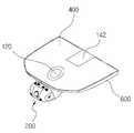
도 1을 참고하면, 일반적으로 차량용 블랙박스는 윈드쉴드(100)나 대쉬보드(dashboard)에 장착하게 된다. 차량용 블랙박스를 윈드쉴드(100)나 대쉬보드에 장착하게 되면 미관상 좋지 못하고 사고에 의한 충격을 받으면 떨어지는 등의 문제점이 있었다.Referring to FIG. 1, a black box for a vehicle is generally mounted on a
특히, 윈드쉴드(100) 중상 상단부에는 룸미러(140), 레인센서(120), 차선이탈경보시스템(LDWS) 등 많은 장치들이 복잡하게 설치되어 있어 블랙박스를 추가로 설치하게 되면 미관상 상당히 보기 좋지 못하다.Especially, many devices such as the
이러한 문제점을 해결하기 위해서 공개특허 제10-2013-0090171호는 룸미러에 설치 가능한 차량용 블랙박스에 관하여 개시하고 있다.In order to solve such a problem, Japanese Patent Application Laid-Open No. 10-2013-0090171 discloses a vehicle black box that can be installed in a room mirror.
그러나 공개특허 제10-2013-0090171호는 룸미러 내부는 블랙박스를 장착하기 위한 공간이 부족하고, 기존에 장착되어 있는 룸미러를 교체하여야 하므로 장착비용이 고가라는 문제점이 있다.
[0007] However, in the conventional art, the space inside the room mirror is insufficient for mounting the black box, and the existing room mirror is required to be replaced, resulting in a high installation cost.
본 발명은 상술한 종래의 문제점을 해결하기 위한 것으로, 다음과 같은 과제의 해결을 목적으로 한다.SUMMARY OF THE INVENTION The present invention has been made to solve the above-mentioned conventional problems, and it is an object of the present invention to solve the following problems.
첫째, 레인센서를 내부에 장착할 수 있는 순정형태의 장착커버 전면에 블랙박스를 장착함으로써 외관이 미려한 차량용 블랙박스를 제공하고자 한다.First, it is intended to provide a black box for a vehicle having a beautiful appearance by mounting a black box on the front surface of a mounting cover of a genuine type in which a rain sensor can be mounted inside.
둘째, 윈드쉴드에 부착해도 차량 운행을 위해 필요한 운전자의 시야를 방해하지 않는 차량용 블랙박스를 제공하고자 한다.Second, we would like to provide a vehicle black box that does not interfere with the driver's vision required for vehicle operation even when attached to a windshield.
셋째, 윈드쉴드에 부착해도 사고 시의 충격에 떨어지지 않는 차량용 블랙박스를 제공하고자 한다.Third, it is intended to provide a black box for a vehicle that is not deteriorated by an impact upon an accident even when it is attached to a windshield.
본 발명의 해결하고자 하는 과제는 이상에서 언급된 것들에 한정되지 않으며, 언급되지 아니한 다른 해결과제들은 아래의 기재로부터 당업자에게 명확하게 이해되어 질 수 있을 것이다.
The problems to be solved by the present invention are not limited to those mentioned above, and other solutions not mentioned can be clearly understood by those skilled in the art from the following description.
본 발명에 따른 차량용 블랙박스는 케이스, 케이스에 장착되어 차량의 전방 상황을 촬영하는 카메라 렌즈 및 케이스에 장착되어 카메라 렌즈에서 촬영된 영상을 처리하여 메모리카드에 기록하는 영상처리회로를 포함하는 촬영기록부를 포함하는 차량용 블랙박스에 있어서, 차량의 윈드쉴드 중앙 상단부에 고정되는 브래킷; 및 상부가 개방되어 레인센서를 내부에 수용하고, 전면부에 상기 촬영기록부가 결합되는 부착대가 형성되어 상기 브래킷에 결합되는 장착커버;를 포함하는 것이 바람직하다.A black box for a vehicle according to the present invention includes a camera case mounted on a case and a case for photographing a forward situation of the vehicle, and an image processing circuit mounted on the case and processing an image photographed by the camera lens, A bracket for a vehicle, comprising: a bracket fixed to a central upper end portion of a windshield of a vehicle; And a mounting cover having an upper portion thereof opened to accommodate the rain sensor therein, and a mounting cover having a front portion to which the recording and recording unit is coupled, the mounting cover being coupled to the bracket.
본 발명에 따른 차량용 블랙박스에 있어서, 케이스는 개방된 후면에 덮개가 결합되고, 부착대는 케이스의 전면부에 형성되는 원형 가이드홈 및 원형 가이드홈의 내주면에 내측으로 돌출 형성되는 복수의 고정턱을 포함하고, 덮개는 원형 가이드홈을 따라 회전하는 원형 가이드돌기 및 원형 가이드돌기의 외측방향 상단부에 일체로 형성되는 걸림턱을 포함하되, 걸림턱은 고정턱에 회전슬라이드 결합되는 것이 바람직하다.In the black box for a vehicle according to the present invention, the cover is coupled to the rear surface of the case, and the attachment stand comprises a circular guide groove formed in the front portion of the case and a plurality of fixing jaws protruding inwardly on the inner circumferential surface of the circular guide groove The lid includes a circular guide protrusion that rotates along the circular guide groove, and a stop protrusion integrally formed on an upper end of the circular guide protrusion in an outward direction, wherein the stop protrusion is rotatably and slidably coupled to the fixed stop.
본 발명에 따른 차량용 블랙박스에 있어서, 장착커버는 중심부에 룸미러를 윈드쉴드에 고정하는 스테이가 통과하는 통공이 형성되고, 장착커버의 내측방향 상단부에 브래킷에 결합되는 복수의 체결홈이 형성되며, 장착커버의 후단부에 배선통과홈이 형성되는 것이 바람직하다.In the black box for a vehicle according to the present invention, the mounting cover has a through hole through which a stay fixing the room mirror to the windshield is formed, and a plurality of coupling grooves are formed at the upper end in the inward direction of the mounting cover to be coupled to the bracket And the wiring passage groove is formed at the rear end of the mounting cover.
본 발명에 따른 차량용 블랙박스에 있어서, 장착커버는 전후방향을 기준으로 좌우로 양분되고, 양분된 장착커버의 결합부분 일측에는 결합홈이 형성되고 타측에는 결합홈에 탈착가능하게 삽입되는 결합돌기가 형성되는 것이 바람직하다.In the black box for a vehicle according to the present invention, the mounting cover is divided into left and right portions with respect to the front-rear direction. The mounting cover is divided into two parts by a coupling protrusion .
본 발명에 따른 차량용 블랙박스에 있어서, 카메라 렌즈는 회전장착대에 결합되고, 회전장착대는 케이스의 개방된 전면 내부 양측에 힌지 결합되어 카메라 렌즈의 촬영각도 조정이 가능한 것이 바람직하다.In the black box for a vehicle according to the present invention, it is preferable that the camera lens is coupled to the rotary mount, and the rotary mount is hinged to both sides of the open front face of the case to adjust the angle of photographing of the camera lens.
본 발명에 따른 차량용 블랙박스에 있어서, 촬영기록부와 장착커버 사이에 하이패스 단말기가 결합되는 것이 바람직하다.
In the black box for a vehicle according to the present invention, it is preferable that a high pass terminal is coupled between the photograph recording portion and the mounting cover.
본 발명에 따른 차량용 블랙박스는 레인센서를 내부에 장착할 수 있는 순정형태의 장착커버 전면에 부착되는 블랙박스를 제공함으로써 다음과 같은 효과를 기대할 수 있다.The black box for a vehicle according to the present invention can be expected to have the following effects by providing a black box attached to the front surface of a mounting cover of a genuine type in which a rain sensor can be mounted inside.
첫째, 윈드쉴드에 부착된 차량용 블랙박스로 인한 미관의 저하를 방지할 수 있다.First, it is possible to prevent deterioration of aesthetics caused by a vehicle black box attached to a windshield.
둘째, 윈드쉴드에 차량용 블랙박스를 부착해도 차량 운행을 위해 필요한 운전자의 시야를 방해하지 않는다.Second, attaching a vehicle black box to a windshield does not interfere with the driver's view necessary for vehicle operation.
셋째, 차량용 블랙박스가 사고 시 충격에도 떨어지지 않으므로, 사고 당시의 영상을 촬열할 수 있고, 떨어진 블랙박스에 의한 2차 부상을 방지할 수 있다.Third, since the black box for a vehicle is not affected by an impact at the time of an accident, it is possible to capture an image at the time of an accident and to prevent a secondary injury caused by a dropped black box.
본 발명의 효과는 이상에서 언급된 것들에 한정되지 않으며, 언급되지 아니한 다른 효과들은 아래의 기재로부터 당업자에게 명확하게 이해되어 질 수 있을 것이다.
The effects of the present invention are not limited to those mentioned above, and other effects not mentioned can be clearly understood by those skilled in the art from the following description.
도 1은 종래의 레인센서와 블랙박스가 장착된 차량의 사시도이다.
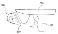
도 2는 본 발명의 일 실시예에 따른 차량용 블랙박스가 장착된 차량의 사시도이다.
도 3은 도 2의 차량용 블랙박스의 사시도이다.
도 4는 도 3의 분해도이다.
도 5는 도 2의 차량용 블랙박스의 정면도이다.
도 6은 도 2의 차량용 블랙박스의 측면도이다.
도 7은 도 2의 차량용 블랙박스에 하이패스 단말기가 결합된 상태를 나타내는 측면도이다.1 is a perspective view of a vehicle equipped with a conventional rain sensor and a black box.
2 is a perspective view of a vehicle equipped with a vehicle black box according to an embodiment of the present invention.
3 is a perspective view of the vehicle black box of Fig.
4 is an exploded view of Fig.
5 is a front view of the vehicle black box of Fig.
6 is a side view of the vehicle black box of Fig. 2;
7 is a side view showing a state in which a high pass terminal is coupled to the vehicle black box of FIG.
이하, 본 발명의 바람직한 실시예에 따른 차량용 블랙박스를 첨부한 도면을 참조하여 상세히 설명한다. 도 2 내지 도 7을 참조하면 본 발명의 일 실시예에 따른 차량용 블랙박스가 도시되어 있다.Hereinafter, a vehicle black box according to a preferred embodiment of the present invention will be described in detail with reference to the accompanying drawings. 2 to 7, there is shown a vehicle black box according to an embodiment of the present invention.
본 발명의 바람직한 실시예에 따른 차량용 블랙박스는 차량에 장착된 레인센서(120)의 순정커버를 제거하고 설치하는 것이 바람직하다.It is preferable that the vehicle black box according to the preferred embodiment of the present invention is installed by removing the genuine cover of the
본 발명에 따른 차량용 블랙박스는 자동차의 주차 또는 운행 중에 발생되는 사고 순간을 촬영하기 위해서 레인센서(120)를 내부에 장착할 수 있는 순정형의 차량용 블랙박스에 관한 것으로서, 케이스(220), 상기 케이스(220)에 장착되어 차량의 전방 상황을 촬영하는 카메라 렌즈(260) 및 상기 케이스(220)에 장착되어 상기 카메라 렌즈(260)에서 촬영된 영상을 처리하여 메모리카드에 기록하는 영상처리회로를 포함하는 촬영기록부(200)를 포함하는 차량용 블랙박스에 있어서, 차량의 윈드쉴드(100) 중앙 상단부에 고정되는 브래킷(400); 및 상부가 개방되어 레인센서(120)를 내부에 수용하고, 전면부에 상기 촬영기록부(200)가 결합되는 부착대(620)가 형성되어 상기 브래킷(400)에 결합되는 장착커버(600);를 포함한다.
A black box for a vehicle according to the present invention is a black box for a vehicle that can mount a
도 2를 참조하면 본 발명에 따른 차량용 블랙박스는 전체적으로 차량의 윈드쉴드(100) 중앙 상단부에 고정되는 브래킷(400), 상기 브래킷(400)에 결합되면서 내부에 레인센서(120)를 수용하는 장착커버(600) 및 상기 장착커버(600)의 전면부에 결합되는 촬영기록부(200)로 구성된다.
Referring to FIG. 2, the vehicle black box according to the present invention includes a
상기 촬영기록부(200)는 종래 차량의 윈드쉴드(100)나 대쉬보드에 부착되어 차량 전방 상황을 찰영하고 기록하는 장치로 일반적으로 블랙박스로 불리는 부분이다. 블랙박스는 장착율이 계속 증가하는 있는 상태로 현재 많은 차량에 보급되어 장착되는 장치다. 촬영기록부(200)의 구성은 일반적인 블랙박스와 기본적으로 동일하므로 간략하게 설명한다.
The photographed
상기 촬영기록부(200)는 내부에 카메라 렌즈(260), 영상처리회로, 메모리카드 등이 결합되는 케이스(220)와 상기 케이스(220)의 후방에 결합되는 덮개(240)를 포함한다. 상기 덮개(240)는 상기 케이스(220)의 후방에 일체로 형성될 수도 있다.
The
도 3에서 알 수 있는 바와 같이, 상기 케이스(220)는 대략 전면 일부분과 후면이 개방된 상자 형태로서, 상기 개방된 전면을 통해 카메라 렌즈(260)가 케이스(220) 외부의 차량 전방 상황을 촬영할 수 있다. 상기 케이스(220)는 양측면을 개방되도록 형성하고, 여기에 분리가능한 측판(222)을 결합할 수도 있다.3, the
도 6에서 알 수 있는 바와 같이, 상기 카메라 렌즈(260)는 회전장착대(290)에 결합되고, 상기 회전장착대(290)는 상기 케이스(220)의 개방된 전면 내부 양측에 힌지(292) 결합되어 상기 카메라 렌즈(260)의 촬영각도 조정이 가능하다. 상기 회전장착대(290)는 상기 힌지(292)를 중심으로 상하로 회전이 가능하므로 상기 카메라 렌즈(260)가 촬영하는 방향을 원하는 위치로 설정할 수 있다.6, the
상기 케이스(220)는 개방된 전면에 카메라 렌즈 부착판(224)을 결합한 후에 상기 회전장착대(290)를 상기 카메라 렌즈 부착판(224)에 힌지(292) 결합하는 것도 가능하다. 상기 회전장착대(260)에는 다수의 각도조절홈(294)이 형성되고, 상기 카메라 렌즈 부착판(224)에는 상기 각도조절홈(294)에 걸려 상기 회전장착대(260)의 회전각도를 유지하는 각도조절탄성바(225)가 형성될 수 있다. 상기 각도조절탄성바(225)는 상기 회전장착대(260)의 각도조절홈(294)에 맞물린 상태로 탄성력이 작용하므로 상기 카메라 렌즈(260)가 소정의 촬영각도를 유지할 수 있게 한다.
It is also possible that the
상기 카메라 렌즈(260)를 통해 촬영된 차량 전방의 영상은 상기 영상처리회로를 통해 메모리카드에 저장된다.An image of the front of the vehicle photographed through the
메모리카드는 컴퓨터, PDA(개인용 휴대정보단말기), PMP(휴대용 멀티미디어재생기), 디지털카메라, MP3 플레이어 등 각종 디지털 전자제품에 두루 사용되는 데이터 저장장치를 말한다. 이러한 메모리카드의 규격은 스마트미디어 카드(SMC), CF(compact flash) 카드, 메모리스틱, SD(secure digital) 카드, 멀티미디어 카드(MMC), xD 픽처(extreme digital picture) 카드 등 크게 6가지 종류가 있으며, 필요에 따라 선택이 가능하다.A memory card refers to a data storage device widely used in various digital electronic products such as a computer, a personal digital assistant (PDA), a portable multimedia player (PMP), a digital camera, and an MP3 player. The specifications of such a memory card are classified into six types such as a smart media card (SMC), a compact flash (CF) card, a memory stick, a secure digital (SD) card, a multimedia card (MMC), and an xD picture , And can be selected as needed.
상기 메모리카드는 메모리카드 슬롯을 통해 상기 영상처리회로에 전기적으로 연결되어 있으며 상기 메모리카드 슬롯에 탈착이 가능하다. 상기 케이스(220)에는 메모리카드 슬롯에 메모리카드를 탈착하기 위한 통로가 형성된다.
The memory card is electrically connected to the image processing circuit through a memory card slot and is detachable from the memory card slot. In the
상기 덮개(240)는 상기 케이스(220)의 후방에 결합되어 상기 촬영기록부(200)를 상기 장착커버(600)에 결합하는 부분이다.The
상기 부착대(620)는 상기 장착커버(600)의 전면부에 형성되는 원형 가이드홈(622) 및 상기 원형 가이드홈(622)의 내주면에 내측으로 돌출 형성되는 복수의 고정턱(624)을 포함하고, 상기 덮개(240)는 상기 원형 가이드홈(622)을 따라 회전하는 원형 가이드돌기(242) 및 상기 원형 가이드돌기(242)의 외측방향 상단부에 일체로 형성되는 걸림턱(244)을 포함한다.The
도 4에 도시된 바와 같이, 상기 걸림턱(244)이 상기 고정턱(624)에 걸리지 않도록 상기 덮개(240)에 형성된 원형 가이드돌기(242)를 상기 부착대(620)에 형성된 원형 가이드홈(622)(고정턱이 형성되지 않은 부분)에 끼우고, 상기 덮개(240)를 회전시키면 상기 원형 가이드돌기(242)가 상기 원형 가이드홈(622)을 따라서 돌게 되어 상기 걸림턱(244)이 상기 고정턱(624)에 걸리게 된다. 상기 촬영기록부(200)는 상기 케이스(220)에 회전슬라이드 결합되어 고정된 상태를 유지하게 된다.4, a
상기 촬영기록부(200)를 상기 장착커버(600)에 회전슬라이드 결합시키면, 차량의 전방, 후방 및 측면에 가해지는 충격 시, 상기 촬영기록부(200)가 상기 장착커버(600)에서 떨어지지 않고, 상기 촬영기록부(200)가 상기 장착커버(600)에 고정된 상태를 안전하게 유지할 수 있게 된다. 물론 상기 촬영기록부(200)를 상기 장착커버(600)에 직선슬라이드 결합 또는 끼움 결합되도록 형성하는 것도 가능하다.
When the
상기 브래킷(400)은 상기 장착커버(600)를 윈드쉴드(100)에 고정하기 위한 것이다. 상부면은 윈드쉴드(100)에 접착제, 양면테이프 등으로 결합되고, 측면에는 상기 장착커버(600)를 고정하기 위한 체결돌기(420)가 형성될 수 있다.The
상기 브래킷(400)의 상부면은 윈드쉴드(100)의 곡선에 대응하는 곡률을 가지도록 형성할 수 있다.The upper surface of the
상기 브래킷(400)의 하부면에는 룸미러(140)를 고정하는 스테이(142)와 레인센서(120)가 결합될 수 있고, 상기 브래킷(400)은 상기 레인센서(120)가 빗방울을 감지할 수 있도록 레인센서(120)의 상측을 가리지 않아야 한다.A
상기 스테이(142)와 레인센서(120)는 윈드쉴드(100)에 직접 고정되거나, 상기 브래킷(400)의 하부면에 고정될 수 있다. 상기 스테이(142)와 레인센서(120)는 상기 윈드쉴드(100)나 브래킷(400)의 하부면에 직접 접착제, 양면테이프 등으로 부착될 수 있으며, 상기 스테이(142)와 레인센서(120)가 윈드쉴드(100)에 직접 고정되는 경우에 상기 브래킷(400)은 상기 레인센서(120)와 스테이(142) 주위를 둘러싸는 형태가 된다.The
상기 브래킷(400)의 하부면에 상기 스테이(142)와 레인센서(120)를 직접 고정하는 경우, 차종에 따라 상기 스테이(142)와 레인센서(120)가 윈드쉴드(100)에 처음 고정되는 위치가 상이하므로, 스테이(142)와 레인센서(120)는 처음 고정위치에서 다른 위치로 이동될 수 있다.When the
상기 브래킷(400)은 레인센서(120)의 순정커버를 제거하고 레인센서(120)를 윈드쉴드(100)에 고정하는 레인센서브래킷을 그대로 사용하는 것도 가능하다.
The
도 5 및 도 6에 참고하면, 상기 장착커버(600)는 전면부에 형성된 부착대(620)에 상기 촬영기록부(200)가 결합되고, 상기 스테이(142)의 상단부 및 레인센서(120)가 수용되어 상기 브래킷(400)에 결합됨으로써, 윈드쉴드(100) 중앙 상단부에 복잡하게 설치된 각종 기기들을 깔끔하게 정리할 수 있다.5 and 6, the
상기 장착커버(600)는 도 3에 도시된 바와 같이 중심부에 룸미러(140)를 윈드쉴드(100)에 고정하는 스테이(142)가 통과하는 통공(640)이 형성되고, 상기 장착커버(600)의 내측방향 상단부에 상기 브래킷(400)에 형성된 체결돌기(420)에 결합되는 복수의 체결홈(650)이 형성되며, 상기 장착커버(600)의 후단부에 배선통과홈(680)이 형성된다. 상기 배선통과홈(680)은 상기 촬영기록부(200) 및 레인센서(120)에 필요한 전기적 연결을 위한 전선이 루프트림쪽으로 빠져나가기 위한 부분이다.3, a through
상기 장착커버(600)는 상단부의 전부 또는 일부를 윈드쉴드(100)에 접착제, 양면테이프 등으로 부착하는 것도 가능하다.The mounting
상기 장착커버(600)는 도 3에 도시된 바와 같이 전후방향을 기준으로 좌우로 양분되고, 양분된 장착커버(600)의 결합부분 일측에는 결합홈(660)이 형성되고 타측에는 상기 결합홈(660)에 탈착가능하게 삽입되는 결합돌기(670)가 형성될 수 있다. 상기 장착커버(600)를 양분하여 형성함으로써 상기 장착커버(600)를 상기 브래킷(400)에 결합하기가 더욱 쉬워져 작업능률이 향상된다. 물론 상기 양분된 장착커버(600)를 볼트 등의 다른 체결 수단으로 결합하는 것도 가능하다.As shown in FIG. 3, the mounting
또한 상기 장착커버(600)에는 상기 촬영기록부(200)에서 촬영된 영상을 표시할 수 있는 LCD 모니터(미도시) 등이 고정 또는 틸팅되도록 장착될 수 있다.
In addition, an LCD monitor (not shown) or the like capable of displaying images photographed by the
현재 국내에 판매되는 차량은 수백여종에 달하며, 각 차종마다 윈드쉴드(100)에 고정되는 스테이(142)와 레인센서(120)의 위치는 상이하다. 따라서, 상기 브래킷(400)과 장착커버(600)는 각 차종의 스테이(142)와 레인센서(120)의 고정위치에 알맞은 형태로 제작할 수 있다. 그리고 차종에 관계없이 상기 스테이(142)와 레인센서(120)를 적당한 위치로 이동하여 장착할 수 있도록 상기 브래킷(400)과 장착커버(600)를 범용 형태로 제작할 수도 있다.
There are several hundreds of vehicles currently sold in the country, and the positions of the
도 7에 도시된 바와 같이, 상기 촬영기록부(200)와 장착커버(600) 사이에 하이패스 단말기(800)가 결합될 수 있다. 하이패스는 고속도로의 톨게이트에 설치되는 자동통행료징수시스템으로서, 톨게이트 입구를 하이패스 단말기(800)가 설치된 차량이 통과하면 통행료에 대한 결제가 자동으로 이루어지는 시스템이다.As shown in FIG. 7, the
종래의 하이패스 단말기(800) 역시 윈드쉴드(100)나 대쉬보드에 장착됨에 따라 미관상으로 좋지 않고, 운전자의 시야를 방해하며, 차량의 사고 발생 시 윈드쉴드(100)나 대쉬보드에서 분리된 하이패스 단말기(800)에 의해 운전자 등이 상해를 입을 수 있다는 문제점이 있었다.The conventional
상술한 문제점을 해결하기 위해서 본 발명에 따른 차량용 블랙박스는 상기 촬영기록부(200)와 장착커버(600) 사이에 하이패스 단말기(800)를 결합할 수 있다.In order to solve the above-described problems, the vehicle black box according to the present invention can combine the
상기 하이패스 단말기(800)는 일측면이 상기 촬영기록부(200)의 덮개(240)에 결합되고, 타측면이 상기 장착커버(600)의 부착대(620)에 결합된다. 여기서 상기 하이패스 단말기(800)의 일측면은 상기 부착대(620)와 마찬가지 형상으로 형성되고, 타측면은 상기 부착대(620)에 결합되는 덮개(240)와 마찬가지 형상으로 형성된다. 상기 촬영기록부(200)와 장착커버(600)는 상기 하이패스 단말기(800)의 전후 양방향에서 촬영기록부(200)가 장착커버(600)에 결합되는 방식과 동일한 방식으로 결합될 수 있다. 물론 상기 하이패스 단말기(800)를 상기 덮개(240)나 부착대(620)에 직선슬라이드 결합 또는 끼움 결합시키는 것도 가능하다.
One side of the
이상에서 설명한 것은 본 발명에 따른 차량용 블랙박스를 실시하기 위한 일부 실시예에 불과한 것으로서, 본 발명은 상기한 실시예에 한정되지 않고, 이하의 특허청구범위에서 청구하는 바와 같이 본 발명의 요지를 벗이남이 없이 당해 발명이 속하는 분야에서 통상의 지식을 가진 자라면 누구든지 다양한 변경실시가 가능한 범위까지 본 발명의 기술적 정신이 있다고 할 것이다.
It is to be understood that the present invention is not limited to the above-described embodiments, but may be modified and changed without departing from the spirit and scope of the invention as defined in the appended claims. It will be understood by those of ordinary skill in the art that various changes and modifications may be made without departing from the spirit and scope of the present invention as defined by the appended claims.
100 : 윈드쉴드120 : 레인센서
140 : 룸미러142 : 스테이
200 : 촬영기록부220 : 케이스
222 : 측판224 : 카메라 렌즈 부착판
225 : 각도조절탄성바240 : 덮개
242 : 원형 가이드돌기244 : 걸림턱
260 : 카메라 렌즈290 : 회전장착대
292 : 힌지294 : 각도조절홈
400 : 브래킷420 : 체결돌기
600 : 장착커버620 : 부착대
622 : 원형 가이드홈624 : 고정턱
640 : 통공650 : 체결홈
660 : 결합홈670 : 결합돌기
680 : 배선통과홈800 : 하이패스 단말기100: Windshield 120: Rain sensor
140: Room mirror 142: stay
200: image recording unit 220: case
222: side plate 224: camera lens attachment plate
225: angle-adjustable elastic bar 240: cover
242: circular guide projection 244:
260: camera lens 290: rotating mount
292: Hinge 294: Angle adjustment groove
400: bracket 420: fastening projection
600: Mounting cover 620: Mounting base
622: circular guide groove 624:
640: through hole 650: fastening groove
660: engaging groove 670: engaging projection
680: wiring passage groove 800: high pass terminal
Claims (6)
Translated fromKorean차량의 윈드쉴드 중앙 상단부에 고정되는 브래킷; 및
상부가 개방되어 레인센서를 내부에 수용하고, 전면부에 상기 촬영기록부가 결합되는 부착대가 형성되어 상기 브래킷에 결합되는 장착커버;를 포함하고,
상기 카메라 렌즈는 회전장착대에 결합되고,
상기 회전장착대는,
상기 케이스의 개방된 전면 내부 양측에 힌지 결합되어 상기 카메라 렌즈의 촬영각도 조정이 가능한 것이며,
상기 회전장착대에는 다수의 각도조절홈이 형성되고,
상기 케이스는 전면에 카메라 렌즈 부착판이 형성되며,
상기 카메라 렌즈 부착판에는 상기 각도조절홈에 걸려 회전장착대의 회전각도를 유지하는 각도조절탄성바를 포함하는 것을 특징으로 하는 차량용 블랙박스.
And a photographing recorder including a case, a camera lens mounted on the case for photographing a forward situation of the vehicle, and an image processing circuit mounted on the case for processing an image photographed by the camera lens and recording the image on a memory card. In the box,
A bracket fixed to a central upper end portion of the windshield of the vehicle; And
And a mounting cover for receiving the rain sensor therein and having an upper portion thereof opened therein and having a mounting portion on the front portion thereof to which the photographing recording portion is coupled to be coupled to the bracket,
The camera lens is coupled to the rotary mount,
The rotation mounting base includes:
And a hinge coupled to both sides of the opened front face of the case so as to adjust the photographing angle of the camera lens,
A plurality of angle adjusting grooves are formed on the rotary mount,
The case has a camera lens mounting plate formed on the front surface thereof,
Wherein the camera lens mounting plate includes an angle adjusting elastic bar which is engaged with the angle adjusting groove to maintain a rotation angle of the rotation mounting base.
상기 케이스는 개방된 후면에 덮개가 결합되고,
상기 부착대는 장착커버의 전면부에 형성되는 원형 가이드홈 및 상기 원형 가이드홈의 내주면에 내측으로 돌출 형성되는 복수의 고정턱을 포함하고,
상기 덮개는 상기 원형 가이드홈을 따라 회전하는 원형 가이드돌기 및 상기 원형 가이드돌기의 외측방향 상단부에 일체로 형성되는 걸림턱을 포함하되,
상기 걸림턱은 상기 고정턱에 회전슬라이드 결합되는 것을 특징으로 하는 차량용 블랙박스.
The method according to claim 1,
The case has a cover attached to an open rear surface,
Wherein the mounting base includes a circular guide groove formed in a front portion of the mounting cover and a plurality of fixing jaws protruding inwardly on an inner circumferential surface of the circular guide groove,
The lid includes a circular guide protrusion that rotates along the circular guide groove, and a stop protrusion formed integrally with an upper end of the circular guide protrusion in an outward direction,
And the engaging jaw is rotatably and slidably engaged with the fixing jaw.
상기 장착커버는 중심부에 룸미러를 윈드쉴드에 고정하는 스테이가 통과하는 통공이 형성되고, 상기 장착커버의 내측방향 상단부에 상기 브래킷에 결합되는 복수의 체결홈이 형성되며, 상기 장착커버의 후단부에 배선통과홈이 형성되는 것을 특징으로 하는 차량용 블랙박스.
The method according to claim 1,
Wherein the mounting cover has a through hole through which a stay for fixing the room mirror to the windshield is formed at a central portion thereof and a plurality of coupling grooves are formed at the upper end in the inward direction of the mounting cover to be coupled to the bracket, Wherein a wiring passage groove is formed in the through hole.
상기 장착커버는 전후방향을 기준으로 좌우로 양분되고, 양분된 장착커버의 결합부분 일측에는 결합홈이 형성되고 타측에는 상기 결합홈에 탈착가능하게 삽입되는 결합돌기가 형성되는 것을 특징으로 하는 차량용 블랙박스.
The method according to claim 1,
Wherein the mounting cover is divided into left and right portions with respect to the front and rear direction, and a coupling protrusion is formed on one side of the coupling portion of the two divided mounting covers, and the coupling protrusion is detachably inserted into the coupling groove on the other side. box.
상기 촬영기록부와 장착커버 사이에 하이패스 단말기가 결합되는 것을 특징으로 하는 차량용 블랙박스.The method according to claim 1,
And a high pass terminal is coupled between the photograph recording section and the mounting cover.
Applications Claiming Priority (2)
| Application Number | Priority Date | Filing Date | Title |
|---|---|---|---|
| KR20130115219 | 2013-09-27 | ||
| KR1020130115219 | 2013-09-27 |
Publications (2)
| Publication Number | Publication Date |
|---|---|
| KR20150035352A KR20150035352A (en) | 2015-04-06 |
| KR101564354B1true KR101564354B1 (en) | 2015-10-29 |
Family
ID=53030335
Family Applications (1)
| Application Number | Title | Priority Date | Filing Date |
|---|---|---|---|
| KR1020140002422AExpired - Fee RelatedKR101564354B1 (en) | 2013-09-27 | 2014-01-08 | Black-box for vehicle |
Country Status (1)
| Country | Link |
|---|---|
| KR (1) | KR101564354B1 (en) |
Families Citing this family (1)
| Publication number | Priority date | Publication date | Assignee | Title |
|---|---|---|---|---|
| KR101809055B1 (en)* | 2015-10-06 | 2017-12-14 | 주식회사 현대오토하우 | Black box for bike |
Citations (2)
| Publication number | Priority date | Publication date | Assignee | Title |
|---|---|---|---|---|
| JP2011046331A (en) | 2009-08-28 | 2011-03-10 | Fujitsu General Ltd | On-vehicle camera device |
| US20120310519A1 (en) | 2004-12-15 | 2012-12-06 | Magna Donnelly Engineering Gmbh | Accessory mounting system for a vehicle |
- 2014
- 2014-01-08KRKR1020140002422Apatent/KR101564354B1/ennot_activeExpired - Fee Related
Patent Citations (2)
| Publication number | Priority date | Publication date | Assignee | Title |
|---|---|---|---|---|
| US20120310519A1 (en) | 2004-12-15 | 2012-12-06 | Magna Donnelly Engineering Gmbh | Accessory mounting system for a vehicle |
| JP2011046331A (en) | 2009-08-28 | 2011-03-10 | Fujitsu General Ltd | On-vehicle camera device |
Also Published As
| Publication number | Publication date |
|---|---|
| KR20150035352A (en) | 2015-04-06 |
Similar Documents
| Publication | Publication Date | Title |
|---|---|---|
| US8040376B2 (en) | Vehicle monitor apparatus | |
| KR100909368B1 (en) | Vehicle rear surveillance camera installation structure | |
| CN108369754B (en) | Recording device for vehicle | |
| WO2010127473A1 (en) | In-vehicle rearview mirror with electronic audio-video recorder | |
| KR20120058208A (en) | Side mirror of vehicle auto folding system and method using camera module | |
| KR101564354B1 (en) | Black-box for vehicle | |
| US20120162420A1 (en) | Vehicle-mounted camera | |
| US20250071399A1 (en) | Vehicle video record system, vehicle, and camera module for the same | |
| CN103503431A (en) | Vehicle-mounted camera | |
| CN214225990U (en) | Vehicle-mounted ETC and DVR camera integrated device | |
| CN104379408A (en) | A reversing camera incorporated into the trademark | |
| KR100613233B1 (en) | Lateral and rear sensing systems for car rearview mirror replacement | |
| KR101508604B1 (en) | Module-type black-box for vehicle | |
| US11067796B2 (en) | Information display system for a vehicle | |
| JP2004196208A (en) | Automobile surroundings recognizing device | |
| KR101808699B1 (en) | Black box hanger | |
| KR100866774B1 (en) | Driver Assistance Camera Unit | |
| JP2020032748A (en) | Electronic mirror | |
| CN213442356U (en) | Vehicle-mounted monitoring device | |
| KR102738750B1 (en) | A vehicle side mirrors capable of forward checking and interlocking system thereof | |
| KR20130059189A (en) | A side mirror system for vehicle | |
| KR20200143840A (en) | a car side camera | |
| CN200992172Y (en) | Mini-size pick-up head and automobile cargo container rear-lid fitted with same | |
| KR200400882Y1 (en) | Outside Watch Device for Vehicle | |
| KR102368173B1 (en) | Car Black Box System with twin-camera at the rear |
Legal Events
| Date | Code | Title | Description |
|---|---|---|---|
| A201 | Request for examination | ||
| PA0109 | Patent application | St.27 status event code:A-0-1-A10-A12-nap-PA0109 | |
| PA0201 | Request for examination | St.27 status event code:A-1-2-D10-D11-exm-PA0201 | |
| D13-X000 | Search requested | St.27 status event code:A-1-2-D10-D13-srh-X000 | |
| D14-X000 | Search report completed | St.27 status event code:A-1-2-D10-D14-srh-X000 | |
| E902 | Notification of reason for refusal | ||
| PE0902 | Notice of grounds for rejection | St.27 status event code:A-1-2-D10-D21-exm-PE0902 | |
| E13-X000 | Pre-grant limitation requested | St.27 status event code:A-2-3-E10-E13-lim-X000 | |
| P11-X000 | Amendment of application requested | St.27 status event code:A-2-2-P10-P11-nap-X000 | |
| P13-X000 | Application amended | St.27 status event code:A-2-2-P10-P13-nap-X000 | |
| E701 | Decision to grant or registration of patent right | ||
| PE0701 | Decision of registration | St.27 status event code:A-1-2-D10-D22-exm-PE0701 | |
| PG1501 | Laying open of application | St.27 status event code:A-1-1-Q10-Q12-nap-PG1501 | |
| GRNT | Written decision to grant | ||
| PR0701 | Registration of establishment | St.27 status event code:A-2-4-F10-F11-exm-PR0701 | |
| PR1002 | Payment of registration fee | St.27 status event code:A-2-2-U10-U11-oth-PR1002 Fee payment year number:1 | |
| PG1601 | Publication of registration | St.27 status event code:A-4-4-Q10-Q13-nap-PG1601 | |
| PN2301 | Change of applicant | St.27 status event code:A-5-5-R10-R11-asn-PN2301 | |
| PN2301 | Change of applicant | St.27 status event code:A-5-5-R10-R14-asn-PN2301 | |
| P14-X000 | Amendment of ip right document requested | St.27 status event code:A-5-5-P10-P14-nap-X000 | |
| P16-X000 | Ip right document amended | St.27 status event code:A-5-5-P10-P16-nap-X000 | |
| Q16-X000 | A copy of ip right certificate issued | St.27 status event code:A-4-4-Q10-Q16-nap-X000 | |
| P22-X000 | Classification modified | St.27 status event code:A-4-4-P10-P22-nap-X000 | |
| LAPS | Lapse due to unpaid annual fee | ||
| PC1903 | Unpaid annual fee | St.27 status event code:A-4-4-U10-U13-oth-PC1903 Not in force date:20181024 Payment event data comment text:Termination Category : DEFAULT_OF_REGISTRATION_FEE | |
| PC1903 | Unpaid annual fee | St.27 status event code:N-4-6-H10-H13-oth-PC1903 Ip right cessation event data comment text:Termination Category : DEFAULT_OF_REGISTRATION_FEE Not in force date:20181024 |