KR101562933B1 - System and method for actuator sensor tag - Google Patents
System and method for actuator sensor tagDownload PDFInfo
- Publication number
- KR101562933B1 KR101562933B1KR1020150051112AKR20150051112AKR101562933B1KR 101562933 B1KR101562933 B1KR 101562933B1KR 1020150051112 AKR1020150051112 AKR 1020150051112AKR 20150051112 AKR20150051112 AKR 20150051112AKR 101562933 B1KR101562933 B1KR 101562933B1
- Authority
- KR
- South Korea
- Prior art keywords
- unit
- actuator
- data
- sensor
- sensor tag
- Prior art date
- Legal status (The legal status is an assumption and is not a legal conclusion. Google has not performed a legal analysis and makes no representation as to the accuracy of the status listed.)
- Expired - Fee Related
Links
Images


Classifications
- G—PHYSICS
- G06—COMPUTING OR CALCULATING; COUNTING
- G06K—GRAPHICAL DATA READING; PRESENTATION OF DATA; RECORD CARRIERS; HANDLING RECORD CARRIERS
- G06K17/00—Methods or arrangements for effecting co-operative working between equipments covered by two or more of main groups G06K1/00 - G06K15/00, e.g. automatic card files incorporating conveying and reading operations
- G—PHYSICS
- G06—COMPUTING OR CALCULATING; COUNTING
- G06K—GRAPHICAL DATA READING; PRESENTATION OF DATA; RECORD CARRIERS; HANDLING RECORD CARRIERS
- G06K19/00—Record carriers for use with machines and with at least a part designed to carry digital markings
- G06K19/06—Record carriers for use with machines and with at least a part designed to carry digital markings characterised by the kind of the digital marking, e.g. shape, nature, code
- G06K19/067—Record carriers with conductive marks, printed circuits or semiconductor circuit elements, e.g. credit or identity cards also with resonating or responding marks without active components
- G06K19/07—Record carriers with conductive marks, printed circuits or semiconductor circuit elements, e.g. credit or identity cards also with resonating or responding marks without active components with integrated circuit chips
- G06K19/0723—Record carriers with conductive marks, printed circuits or semiconductor circuit elements, e.g. credit or identity cards also with resonating or responding marks without active components with integrated circuit chips the record carrier comprising an arrangement for non-contact communication, e.g. wireless communication circuits on transponder cards, non-contact smart cards or RFIDs
Landscapes
- Engineering & Computer Science (AREA)
- Physics & Mathematics (AREA)
- General Physics & Mathematics (AREA)
- Theoretical Computer Science (AREA)
- Computer Networks & Wireless Communication (AREA)
- Computer Hardware Design (AREA)
- Microelectronics & Electronic Packaging (AREA)
- Arrangements For Transmission Of Measured Signals (AREA)
Abstract
Translated fromKoreanDescription
Translated fromKorean본 발명은 액추에이터 센서 태그 시스템 및 방법에 관한 것으로, 더욱 상세하게는 IoT 기반에서 온/오프 또는 H/L 신호 제어가 필요한 다양한 디바이스에 RFID 데이터에 따라 스위칭을 수행하기 위해 RFID 태그 데이터에 연동하는 SOC 형태의 액추에이터를 제어, 실행시킬 수 있는 액추에이터 센서 태그 시스템 및 방법에 관한 것이다.The present invention relates to an actuator sensor tag system and method. More particularly, the present invention relates to an actuator sensor tag system and method, and more particularly, to an actuator sensor tag system and method for controlling an on / off or H / The present invention relates to an actuator sensor tag system and method capable of controlling and executing an actuator of the shape of an actuator.
IoT(Internet of Things)란 통신 가능한 모든 사물들을 네트워크에 연결하여 상호 통신 수행이 가능한 개념을 의미한다. 시스템적으로 인지할 수 있는 모든 객체는 Things 또는 Objects로 분류하며, 여기에는 RFID를 포함한 근거리 및 원거리 통신 기능을 탑재하고, 센서 등 데이터 생산 및 이용이 가능한 사물(또는 센서 노드) 또는 사람이 이에 포함될 수 있다.IoT (Internet of Things) is a concept that enables communication with all objects that can communicate with each other through a network. All objects that can be systematically recognized are classified as Things or Objects, which include near and far communication functions including RFID, objects (or sensor nodes) capable of producing and using data, such as sensors, .
또한, 인터넷은 컴퓨터만을 위한 네트워크를 넘어 모바일 및 임베디드 디바이스의 영역까지 확장되고 있으며, 막대한 양의 지능형 사물(예를 들어, 무선 센서, 액추에이터 또는 임베디드 디바이스)에 의해서 다양한 웹 콘텐츠가 생성 및 공유되고 있다.In addition, the Internet has expanded beyond the computer-only network to the areas of mobile and embedded devices, and various web contents have been created and shared by an enormous amount of intelligent objects (e.g., wireless sensors, actuators or embedded devices) .
기존의 인터넷은 자원(resource)이 충분한 컴퓨터와 같은 장치들 사이에서 사용되어 왔지만, 센서, RFID 등과 같은 사물간 통신까지 포함하도록 확장된 IoT 환경에서는 상대적으로 자원이 제한된 장치간의 통신을 기반으로 데이터를 송수신하여 사물로부터 정보를 얻거나 제어할 수 있어야 하므로 최소한의 자원으로 이를 지원하기 위한 기술이 필요하다.Although the existing Internet has been used among devices such as computers with sufficient resources, in the extended IoT environment including the inter-object communication such as the sensor and the RFID, the data is transmitted based on the communication between the devices with relatively limited resources Since it is necessary to be able to receive and control information from objects by sending and receiving, there is a need for a technique to support this with a minimum of resources.
최근 마이크로프로세서와 무선 통신 기술의 발전으로 IoT의 지능형 사물을 개발하기 위한 실질적 단계에 있으나, HTTP/TCP, HTML, Javascript와 같은 기존 인터넷 환경의 웹 콘텐츠 기술은 센서네트워크와 같은 제한된 환경 및 디바이스에 적용하기에는 아직 무겁고 복잡하여 적합하지 않다.Recent developments of microprocessor and wireless communication technologies are at the practical stage to develop intelligent objects of IoT, but web contents technology of existing Internet environment such as HTTP / TCP, HTML, Javascript is applied to limited environments and devices such as sensor networks It is still too heavy and complicated to fit in.
본 발명은 전술한 바와 같은 종래의 문제점을 해결하고자 안출된 것으로서, 그의 목적은 IoT 기반에서 온/오프 또는 H/L 신호 제어가 필요한 다양한 디바이스에 RFID 데이터에 따라 스위칭을 수행하기 위해 RFID 태그 데이터에 연동하는 SOC 형태의 액추에이터를 제어, 실행시킬 수 있는 액추에이터 센서 태그 시스템 및 방법을 제공하기 위한 것이다.SUMMARY OF THE INVENTION The present invention has been made to solve the conventional problems as described above, and it is an object of the present invention to provide a method and apparatus for switching RFID tags on various devices requiring On / Off or H / And an actuator sensor tag system and method capable of controlling and executing an SOC type actuator interlocked with each other.
본 발명에 따른 액추에이터 센서 태그 시스템은, 하나 이상의 디바이스에 대하여 RFID 태그 데이터 메모리부에 저장되는 RFID 데이터에 따라 디바이스의 스위칭을 수행하기 위해 RFID 태그 데이터에 연동하는 액추에이터를 제어하고, 상기 디바이스의 스위칭 제어를 위해서 디바이스에 관련된 환경 정보에 대한 센서 데이터를 획득하는 액추에이터 센서 태그부; 상기 액추에이터 센서 태그부에서부터 디바이스의 ID를 획득하고 상기 액추에이터의 동작을 제어하기 위한 명령 데이터를 상기 액추에이터 센서 태그부에 전송하여 상기 액추에이터 센서 태그부의 메모리부에 데이터를 읽어 들이거나 저장 제어하는 IoT 리더부; 상기 IoT 리더부와 통신하여 디바이스의 스위칭 제어를 위한 명령 데이터를 상기 IoT 리더부에 전송하여 상기 IoT 리더부를 제어하기 위한 인터페이스를 구비하는 응용 프로그램부; 및 상기 액추에이터 센서 태그부에 연동되어 상기 액추에이터 센서 태그부의 액추에이터의 출력 신호에 따라 스위칭 제어되는 디바이스에 온/오프 또는 구동 동작을 수행하는 스위칭 실행부를 포함하는 것을 특징으로 하는 것이다.An actuator sensor tag system according to the present invention controls an actuator linked to RFID tag data to perform switching of a device according to RFID data stored in an RFID tag data memory unit for one or more devices, An actuator sensor tag unit for acquiring sensor data on environmental information related to the device for the sensor information; An IoT reader unit for acquiring an ID of a device from the actuator sensor tag unit and transmitting command data for controlling an operation of the actuator to the actuator sensor tag unit to read or store data in a memory unit of the actuator sensor tag unit; ; An application program unit having an interface for communicating with the IoT reader unit to transmit command data for switching control of the device to the IoT reader unit and controlling the IoT reader unit; And a switching execution unit operable to perform on / off or drive operation of the device interlocked with the actuator sensor tag unit and controlled in accordance with an output signal of the actuator of the actuator sensor tag unit.
또한, 본 발명에 따른 액추에이터 센서 태그 시스템에 있어서, 상기 액추에이터 센서 태그부는 SOC 형태의 RFID 블록과 센서 태그 연동 블록을 포함하는 것을 특징으로 하는 것이다.Further, in the actuator sensor tag system according to the present invention, the actuator sensor tag unit includes an SOC type RFID block and a sensor tag interlocking block.
또한, 본 발명에 따른 액추에이터 센서 태그 시스템에 있어서, 상기 액추에이터 센서 태그부는, RFID 태그 데이터를 저장하여 상기 IoT 리더부에 디바이스의 ID를 전송하고 상기 액추에이터의 동작을 제어하기 위한 명령 데이터를 받아들여서 저장하는 메모리부; 상기 스위칭 제어되는 디바이스의 온/오프 또는 구동을 위한 하이레벨 또는 로우 레벨의 스위칭 신호를 출력하는 액추에이터; 외부의 환경 조건에 대한 인터페이스를 제공하여 환경 정보에 대한 센서 정보를 획득하는 센서 연동부; 및 상기 액추에이터의 하이 레벨 또는 로우 레벨의 스위칭 신호를 출력 제어하고, 상기 센서 연동부의 환경 정보 데이터를 입력받아서 상기 메모리부에 저장하는 디지털 통신/제어부를 포함하는 것을 특징으로 하는 것이다.Also, in the actuator sensor tag system according to the present invention, the actuator sensor tag unit stores RFID tag data, transmits an ID of the device to the IoT reader unit, receives command data for controlling the operation of the actuator, ; An actuator for outputting a high level or low level switching signal for on / off or driving of the switching controlled device; A sensor interlocking unit that provides an interface to external environmental conditions to acquire sensor information on environmental information; And a digital communication / control unit for controlling output of the high-level or low-level switching signal of the actuator, receiving environmental information data of the sensor interlocking unit, and storing the received environmental information data in the memory unit.
또한, 본 발명에 따른 액추에이터 센서 태그 시스템에 있어서, 상기 디지털 통신/제어부는 RFID 프로토콜과 내부 MCU를 포함하고 있는 것을 특징으로 하는 것이다.Further, in the actuator sensor tag system according to the present invention, the digital communication / control unit includes an RFID protocol and an internal MCU.
또한, 본 발명에 따른 액추에이터 센서 태그 시스템에 있어서, 상기 메모리부에는 액추에이터 센서 태그 데이터를 처리하기 위한 센서 프로토콜 컨트롤 정보로서, 센서 프로토콜 컨트롤 정보 길이, 센서 번호, 센서 타입, 데이터 길이, 센서 주소를 포함하고 있는 것을 특징으로 하는 것이다.In the actuator sensor tag system according to the present invention, the memory unit includes sensor protocol control information length, a sensor number, a sensor type, a data length, and a sensor address as sensor protocol control information for processing actuator sensor tag data And the like.
또한, 본 발명에 따른 액추에이터 센서 태그 시스템에 있어서, 상기 IoT 리더부는, 상기 액추에이터 센서 태그부와 통신하여 RFID 태그 데이터를 읽어들이거나 데이터를 전송하여 저장하는 RFID 리더 모듈; 상기 액추에이터 센서 태그부의 메모리부로부터 센서태그의 메모리 데이터를 얻어오는 메모리 획득 모듈; 상기 액추에이터 센서 태그부의 메모리부에 명령 데이터를 입력하여 기록하는 메모리 기록 모듈; 및 상기 응용 프로그램부에 통신 인터페이스를 제공하여 응용 프로그램부로부터 명령 데이터를 입력받는 통신모듈을 포함하는 것을 특징으로 하는 것이다.Further, in the actuator sensor tag system according to the present invention, the IoT reader unit may include an RFID reader module for communicating with the actuator sensor tag unit to read RFID tag data or transmit and store data; A memory acquisition module for acquiring memory data of the sensor tag from the memory unit of the actuator sensor tag unit; A memory recording module for inputting and recording command data in a memory unit of the actuator sensor tag unit; And a communication module for providing the communication interface to the application program unit and receiving command data from the application program unit.
또한, 본 발명에 따른 액추에이터 센서 태그 시스템에 있어서, 상기 스위칭 실행부는, 상기 액추에이터 센서 태그부로부터 액추에이터의 하이레벨 또는 로우 레벨의 스위칭 신호를 획득하고 스위칭 신호를 판단하여 온/오프 또는 구동 신호를 받아들이는 액추에이터 판단 모듈; 및 상기 액추에이터 센서 태그부의 상기 액추에이터의 하이레벨 또는 로우 레벨의 스위칭 신호에 따라 연동되는 디바이스의 스위치에 온/오프 또는 구동 동작을 수행 처리하는 스위칭 연동 모듈을 포함하는 것을 특징으로 하는 것이다.Further, in the actuator sensor tag system according to the present invention, the switching execution unit may acquire a high-level or low-level switching signal of the actuator from the actuator sensor tag unit, judge a switching signal, An actuator determination module; And a switching interlocking module for performing an on / off or a driving operation on a switch of a device interlocked with the high-level or low-level switching signal of the actuator of the actuator sensor tag unit.
또한, 본 발명에 따른 액추에이터 센서 태그 시스템에 있어서, 상기 응용 프로그램부는, 상기 IoT 리더부에 명령 데이터를 전송하여 처리하도록 제어하는 명령 처리 모듈; 상기 IoT 리더부를 통하여 스위칭 제어를 요청할 디바이스 ID를 선택하기 위해 메모리 데이터를 획득하는 메모리 선택 모듈; 상기 IoT 리더부를 통하여 상기 선택된 디바이스 ID에 대한 스위칭 제어 명령 데이터를 기록 처리하기 위한 인터페이스를 제공하는 데이터 처리 모듈; 및 상기 IoT 리더부와 명령 데이터를 전송하기 위한 통신 모듈을 포함하는 것을 특징으로 하는 것이다.Further, in the actuator sensor tag system according to the present invention, the application program unit may include: a command processing module that controls the IoT reader unit to transmit and process command data; A memory selection module for acquiring memory data to select a device ID for requesting switching control through the IoT reader; A data processing module for providing an interface for recording switching control command data for the selected device ID through the IoT reader unit; And a communication module for transmitting the command data to the IoT reader unit.
한편, 본 발명에 따른 액추에이터 센서 태그 방법은, 응용 프로그램부는 IoT리더부로 스위칭 제어할 디바이스에 대한 명령 데이터를 전송하는 단계; IoT 리더부는 액추에이터 센서 태그부에서 디바이스 ID를 획득하고 제어 명령을 액추에이터 센서 태그부의 메모리에 기록하는 단계; 액추에이터 센서 태그부는 RFID 프로토콜에 따라서 메모리부에 기록된 디바이스 ID에 대한 제어 명령 데이터에 따라 액추에이터를 제어하는 단계; 및 스위칭 실행부는 액추에이터 센서 태그부의 액추에이터 출력 신호에 따라 디바이스의 온/오프 또는 구동 스위치를 연동 실행하는 단계를 포함하는 것을 특징으로 하는 것이다.According to another aspect of the present invention, there is provided an actuator sensor tag method, comprising: transmitting an instruction data to a device to be switched to an IoT reader unit; The IoT reader acquiring a device ID in an actuator sensor tag unit and writing a control command in a memory of an actuator sensor tag unit; Controlling the actuator according to control command data for the device ID recorded in the memory unit according to the RFID protocol; And the switching execution unit includes a step of interlocking the on / off or drive switch of the device in accordance with the actuator output signal of the actuator sensor tag unit.
또한, 본 발명에 따른 액추에이터 센서 태그 방법에 있어서, 상기 IoT 리더부가 액추에이터 센서 태그부에서 디바이스 ID를 획득하고 제어 명령을 액추에이터 센서 태그부의 메모리에 기록하는 단계에서, 액추에이터 센서 태그부는 센서 연동부를 통하여 외부의 환경 정보에 대한 센서 데이터를 획득하고 메모리부에 저장하는 단계를 더 포함하는 것을 특징으로 하는 것이다.In the actuator sensor tag method according to the present invention, in the step of the IoT reader acquiring the device ID in the actuator sensor tag unit and writing the control command in the memory of the actuator sensor tag unit, the actuator sensor tag unit, Acquiring sensor data on the environmental information of the sensor and storing the sensor data in the memory unit.
본 발명은 RFID 태그 데이터에 연동하는 SOC 형태의 액추에이터를 제어, 실행시켜서 IoT 기반에서 온/오프 또는 H/L 신호 제어가 필요한 다양한 디바이스에 RFID 데이터에 따라 스위칭을 처리할 수 있는 효과가 있다.The present invention has an effect of controlling an SOC-type actuator interlocked with RFID tag data and performing switching according to RFID data in various devices requiring on / off or H / L signal control based on IoT.
또한, 환경 정보 데이터를 센서 태그 데이터로서 메모리에 기록하고 이를 피드백 정보로 하여 RFID 태그 데이터에 액추에이터를 제어, 실행시켜서 온/오프 또는 H/L 신호 제어가 필요한 다양한 디바이스에 RFID 데이터에 따라 스위칭을 처리할 수 있도록 할 수 있다.In addition, environmental information data is recorded in the memory as sensor tag data, and the actuator is controlled and executed on the RFID tag data as feedback information, thereby switching on various devices requiring ON / OFF or H / L signal control according to the RFID data Can be done.
또한, 사물 기기가 제공하는 사물 인터넷 서비스를 제공받기 위한 사전 절차에 해당하는 AP 접속과 사물 기기 연결 절차를 위해 사용자에게 태그 인터페이스를 제공하여, 사용자의 편리성과 신속성을 증대시킬 수 있게 된다.In addition, the tag interface is provided to the user for the AP connection and the object device connection procedure corresponding to the preliminary procedure for receiving the object Internet service provided by the object device, so that the convenience and speed of the user can be increased.
도1은 본 발명에 따른 액추에이터 센서 태그 시스템의 전체 구성도이다.
도2는 본 발명에 따른 액추에이터 센서 태그 시스템의 전체 구성도에서 액추에이터 센서태그부의 상세 구성 블록도이다.
도3은 도2에 도시된 액추에이터 센서 태그부의 메모리부의 상세 구성 블록도이다.
도4는 도3에 도시된 액추에이터 센서 태그부의 메모리부에서 사용자 영역의 메모리 데이터 구조의 상세 구성 블록도이다.
도5는 도3에 도시된 액추에이터 센서 태그부의 메모리부에서 사용자 영역의 메모리 데이터 구조의 일실시예이다.
도6은 본 발명에 따른 액추에이터 센서 태그 시스템의 전체 구성도에서 IoT 리더부의 상세 구성 블록도이다.
도7은 본 발명에 따른 액추에이터 센서 태그 시스템의 스위칭 실행부의 상세 구성 블록도이다.
도8은 본 발명에 따른 액추에이터 센서 태그 시스템의 응용 프로그램부의 상세 구성 블록도이다.
도9는 본 발명에 따른 액추에이터 센서 태그 처리 방법의 흐름도이다.1 is an overall configuration diagram of an actuator sensor tag system according to the present invention.
2 is a detailed block diagram of an actuator sensor tag unit in an overall configuration diagram of an actuator sensor tag system according to the present invention.
3 is a detailed block diagram of a memory unit of the actuator sensor tag unit shown in FIG.
4 is a detailed block diagram of a memory data structure of a user area in a memory unit of the actuator sensor tag unit shown in FIG.
5 is an embodiment of a memory data structure of a user area in the memory unit of the actuator sensor tag unit shown in FIG.
6 is a detailed block diagram of the IoT reader in the overall configuration of the actuator sensor tag system according to the present invention.
7 is a detailed block diagram of a switching execution unit of an actuator sensor tag system according to the present invention.
8 is a detailed block diagram of an application program unit of an actuator sensor tag system according to the present invention.
9 is a flowchart of an actuator sensor tag processing method according to the present invention.
이하, 첨부된 도면을 참조하면서 본 발명의 실시예에 따른 액추에이터 센서 태그 시스템 및 방법에 대해 상세히 설명하기로 한다.Hereinafter, an actuator sensor tag system and method according to an embodiment of the present invention will be described in detail with reference to the accompanying drawings.
도1은 본 발명에 따른 액추에이터 센서 태그 시스템의 전체 구성도이다.1 is an overall configuration diagram of an actuator sensor tag system according to the present invention.
도1을 참조하면, 본 발명의 실시예에 따른 액추에이터 센서 태그 시스템은 디바이스의 스위칭을 위해서 RFID 태그 데이터에 의하여 제어되는 액추에이터를 포함하는 액추에이터 센서 태그부(100)와, 상기 액추에이터 센서 태그부(100)에 제어 명령 데이터를 기록하거나 처리하는 IoT 리더부(200)와, 상기 액추에이터 센서 태그부(100)에 연동하여 디바이스의 스위칭 동작을 제어하는 스위칭 실행부(300)와, 상기 IoT 리더부(200)에 제어 명령을 전달하고 사용자 인터페이스를 제공하는 응용프로그램부(400)를 포함하여 이루어진다.Referring to FIG. 1, an actuator sensor tag system according to an embodiment of the present invention includes an actuator
상기 액추에이터 센서 태그부(100)는 하나 이상의 디바이스에 대하여 RFID 태그 데이터 메모리부에 저장되는 RFID 데이터에 따라 디바이스의 스위칭을 수행하기 위해 RFID 태그 데이터에 연동하는 액추에이터를 제어하고, 상기 디바이스의 스위칭 제어를 위해서 디바이스에 관련된 환경 정보에 대한 센서 데이터를 획득한다.The actuator
이를 위해 상기 액추에이터 센서 태그부(100)는 바람직하게는 SOC(System On Chip)형태의 RFID 블록과 센서 태그 연동 블록으로 구성될 수 있다.To this end, the actuator
상기 액추에이터 센서 태그부(100)는 액추에이터 기능에 따라 실제 디바이스에 연결된 스위칭실행부(300)와 연동하여 디바이스의 온/오프 제어를 수행하게 한다.The actuator
또한, IoT 리더부(200)는 상기 액추에이터 센서 태그부(100)에서부터 디바이스의 ID를 획득하고 액추에이터의 동작을 제어하기 위한 명령 데이터를 상기 액추에이터 센서 태그부(100)에 전송하여 상기 액추에이터 센서 태그부의 메모리부에 데이터를 읽어 들이거나 저장 제어한다.The IoT
상기 액추에이터 센서 태그부(100)와 IoT 리더부(200)는 무선으로서 연결되어 센서 데이터를 인식하고 통신한다.The actuator
그리고, 상기 응용 프로그램부(400)는 상기 IoT 리더부(200)와 통신하여 디바이스의 스위칭 제어를 위한 명령 데이터를 상기 IoT 리더부(200)에 전송하여 상기 IoT 리더부(200)를 제어하기 위한 인터페이스를 구비한다.The
상기 응용 프로그램부(400)는 응용프로그램의 기능 수행에 따라 IoT 리더부(200)에 명령을 최초로 전송하는 것으로, 사용자 인터페이스를 제공하는 PC, 또는 모바일 장치 또는 인터넷에 연결된 다양한 단말 장치가 될 수 있다.The
그리고, 상기 스위칭 실행부(400)는 상기 액추에이터 센서 태그부(100)에 연동되어 상기 액추에이터 센서 태그부(100)의 액추에이터의 출력 신호에 따라 스위칭 제어되는 디바이스에 온/오프 또는 구동 동작을 수행하게 된다.The
상기 스위칭 실행부(400)에 연동되거나 연결되어 액추에이터 센서태그부(100)의 출력신호에 따라 스위칭 구동되는 디바이스는 예를들면 LED 램프, 형광등, 도어록, 솔레노이드 밸브에서 온/오프 구동되는 것이다.A device connected to or connected to the
도2는 본 발명에 따른 액추에이터 센서 태그 시스템의 전체 구성도에서 액추에이터 센서태그부의 상세 구성 블록도이다.2 is a detailed block diagram of an actuator sensor tag unit in an overall configuration diagram of an actuator sensor tag system according to the present invention.
도2를 참조하면, 상기 액추에이터 센서 태그부에는 디지털 통신/제어부(110), 메모리부(120), 액추에이터(130), 센서 연동부(140)를 포함한다.Referring to FIG. 2, the actuator sensor tag unit includes a digital communication /
상기 메모리부(120)는 RFID 태그 데이터를 저장하여 상기 IoT 리더부(200)에 디바이스의 ID를 전송하고 상기 액추에이터(130)의 동작을 제어하기 위한 명령 데이터를 받아들여서 저장한다. The
그리고, 상기 액추에이터(130)는 상기 스위칭 제어되는 디바이스의 온/오프 또는 구동을 위한 하이 레벨 또는 로우 레벨의 스위칭 신호를 출력하는 것이다.The
여기에서, 상기 액추에이터(130)는 MEMS Latch로서 구성될 수 있다.Here, the
또한, 센서 연동부(140)는 외부의 환경 조건에 대한 인터페이스를 제공하여 환경 정보에 대한 센서 정보를 획득하는 것이다.In addition, the
상기 센서 연동부(140)는 외부의 센서(온도/습도 등)의 연동을 위한 인터페이스를 제공하여 센서 정보를 획득한다.The
그리고, 상기 디지털 통신/제어부(110)는 상기 액추에이터의 하이 레벨 또는 로우 레벨의 스위칭 신호를 출력 제어하고, 상기 센서 연동부(140)의 환경 정보 데이터를 입력받아서 상기 메모리부(120)에 저장하는 것이다.The digital communication /
상기 디지털 통신/제어부(110)는 바람직하게는 RFID 프로토콜과 내부 MCU를 포함하고 있는 것이다.The digital communication /
상기 RFID 프로토콜은 예를 들면 ISO/IEC 18000-6C로 구성되고 내부 MCU는 Microcontroller unit로 액추에이터(130)의 출력신호 High/Low를 제어하고 센서 연동부(140)의 데이터를 입력받아서 센서 정보데이터를 메모리부(120)에 저장한다.The RFID protocol is composed of, for example, ISO / IEC 18000-6C, and the internal MCU controls the output signal High / Low of the
도3은 도2에 도시된 액추에이터 센서 태그부의 메모리부의 상세 구성 블록도이다.3 is a detailed block diagram of a memory unit of the actuator sensor tag unit shown in FIG.
도3을 참조하면, 상기 메모리부(120)는 BANK0(Reserved 00), BANK1(EPC 01), BANK2(Tag ID 10), BANK3(User 11)와 같이 총 4개의 BANK 영역으로 구성되어 있다.3, the
BANK0(121)은 Kill/Access Password를 넣는 메모리 데이터 영역에 해당한다.
BANK1(122)은 EPC(Electronic Product Code)의 ID를 넣는 메모리 데이터 영역에 대응한다.
BANK2(123)는 TID(Tag Identification)의 정보를 넣는 메모리 데이터 영역에 해당한다.
BANK3(124)는 사용자 영역으로 SPC(Sensor Protocol Control)와 센서 데이터의 정보를 넣는 메모리 데이터 영역에 해당한다.
도4는 도3에 도시된 액추에이터 센서 태그부의 메모리부에서 사용자 영역의 메모리 데이터 구조의 상세 구성 블록도이다.4 is a detailed block diagram of a memory data structure of a user area in a memory unit of the actuator sensor tag unit shown in FIG.
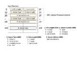
도4에서 참조하면, 상기 메모리부(120)의 사용자 영역에는 액추에이터 센서 태그 데이터를 처리하기 위한 센서 프로토콜 컨트롤 정보로서, 센서 프로토콜 컨트롤 정보 길이, 센서 번호, 센서 타입, 데이터 길이, 센서 주소를 포함하고 있다.Referring to FIG. 4, the user area of the
0F-nF 열에는 SPC 정보가 들어 있고 예를들어 센서 어드레스가 0x30이면 메모리 데이터 0x30의 주소가 센서 데이터의 시작 주소임을 나타낸다.If the 0F-nF column contains SPC information and the sensor address is 0x30, for example, the address of the memory data 0x30 is the start address of the sensor data.
센서타입의 예를 들면 0:액추에이터, 1:온도 센서, 2:습도 센서로 정의되어 있다.For example, the sensor type is defined as 0: actuator, 1: temperature sensor, and 2: humidity sensor.
도5는 도3에 도시된 액추에이터 센서 태그부의 메모리부에서 사용자 영역의 메모리 데이터 구조의 일실시예이다.5 is an embodiment of a memory data structure of a user area in the memory unit of the actuator sensor tag unit shown in FIG.
도5를 참조하면, SPC 정보 길이는 2로서 3word로 되어 있고, 센서 번호는 1(1개)이고, 센서 타입은 0으로 액추에이터로 지정되어 있다.Referring to FIG. 5, the SPC information length is 2 words, 3 words, the sensor number is 1 (one), and the sensor type is 0 and designated by an actuator.
센서 데이터 길이는 0으로 1word로 되어 있고 센서 어드레스는 50으로 주소는 0x50 번지임을 나타내며, 센서 데이터는 01로서 액추에이터 출력신호의 레벨이 High임을 나타내는 것이다.The sensor data length is 0, 1 word, the sensor address is 50, the address is 0x50, and the sensor data is 01, indicating that the level of the actuator output signal is High.
도6은 본 발명에 따른 액추에이터 센서 태그 시스템의 전체 구성도에서 IoT 리더부의 상세 구성 블록도이다.6 is a detailed block diagram of the IoT reader in the overall configuration of the actuator sensor tag system according to the present invention.
도6을 참조하면, 상기 IoT 리더부(200)는 RFID 리더모듈(210), 통신모듈(220), 센서 태그 연동모듈(230)을 포함한다.Referring to FIG. 6, the
상기 RFID 리더모듈(210)은 상기 액추에이터 센서 태그부(100)와 통신하여 RFID 태그 데이터를 읽어들이거나 데이터를 전송하여 저장한다.The
상기 통신 모듈(220)은 상기 응용 프로그램부(400)에 통신 인터페이스를 제공하여 응용 프로그램부(400)로부터 명령 데이터를 입력받는 것이다.The
상기 센서태그 연동모듈(230)에는 상기 액추에이터 센서 태그부(100)의 메모리부(120)로부터 센서태그의 메모리 데이터를 얻어오는 메모리 획득 모듈(231)과, 상기 액추에이터 센서 태그부(100)의 메모리부(120)에 명령 데이터를 입력하여 기록하는 메모리 기록 모듈(232)을 포함한다.The sensor
도7은 본 발명에 따른 액추에이터 센서 태그 시스템의 스위칭 실행부의 상세 구성 블록도이다.7 is a detailed block diagram of a switching execution unit of an actuator sensor tag system according to the present invention.
도7을 참조하면, 상기 스위칭 실행부(300)에는 액추에이터 판단모듈(310)과 스위칭 연동 모듈(320)을 포함한다.Referring to FIG. 7, the switching
상기 액추에이터 판단모듈(310)은 상기 액추에이터 센서 태그부(100)로부터 액추에이터(130)의 하이레벨 또는 로우 레벨의 스위칭 신호를 획득하고 스위칭 신호를 판단하여 온/오프 또는 구동 신호를 받아들이는 것이다.The
또한, 스위칭 연동모듈(320)은 상기 액추에이터 센서 태그부(100)의 상기 액추에이터(130)의 하이레벨 또는 로우 레벨의 스위칭 신호에 따라 연동되는 디바이스 즉, 예를들면 LED 램프, 형광등, 도어록, 솔레노이드 밸브의 스위치에 온/오프 또는 구동 동작을 수행 처리하게 된다.The switching
도8은 본 발명에 따른 액추에이터 센서 태그 시스템의 응용 프로그램부의 상세 구성 블록도이다.8 is a detailed block diagram of an application program unit of an actuator sensor tag system according to the present invention.
도8을 참조하면, 상기 응용 프로그램부(400)에는 명령 처리 모듈(410), 통신모듈(420), 센서 태그 연동 모듈(430)을 포함한다.Referring to FIG. 8, the
상기 명령 처리 모듈(410)은 상기 IoT 리더부(200)에 명령 데이터를 전송하여 처리하도록 제어하는 것이다.The
또한, 통신 모듈(420)은 상기 IoT 리더부(200)와 명령 데이터를 전송하기 위한 것이다.In addition, the
상기 센서 태그 연동 모듈(430)에는 메모리 선택 모듈(431)과 데이터 처리 모듈(432)를 포함한다.The sensor
상기 메모리 선택 모듈(431)은 상기 IoT 리더부(200)를 통하여 스위칭 제어를 요청할 디바이스 ID를 선택하기 위해 메모리부(120)의 메모리 데이터 영역을 획득하기 위한 것이다.The
또한, 상기 데이터 처리 모듈(432)은 상기 IoT 리더부(200)를 통하여 상기 선택된 디바이스 ID에 대한 스위칭 제어 명령 데이터를 기록 처리하기 위한 인터페이스를 제공하는 것이다.In addition, the
상기 응용프로그램부(400)의 통신 모듈(420)은 사용자 인터페이스를 제공하는 PC, 또는 모바일 장치 또는 인터넷에 연결된 다양한 단말 장치가 될 수 있다.The
도9는 본 발명에 따른 액추에이터 센서 태그 처리 방법의 흐름도이다.9 is a flowchart of an actuator sensor tag processing method according to the present invention.
도9를 참조하여 본 발명에 따른 액추에이터 센서 태그 처리 방법은 다음과 같이 진행된다.Referring to FIG. 9, an actuator sensor tag processing method according to the present invention proceeds as follows.
먼저, 응용 프로그램부(400)는 IoT리더부(200)로 스위칭 제어할 디바이스에 대한 명령 데이터를 전송하게 된다(S10).First, the
이를 위해서, IoT 리더부(200)는 액추에이터 센서 태그부(100)에서 디바이스 ID를 획득하고 제어 명령을 액추에이터 센서 태그부(100)의 메모리부(120)에 기록한다(S20).To this end, the
또한, 액추에이터 센서 태그부(100)는 RFID 프로토콜에 따라서 메모리부(120)에 기록된 디바이스 ID에 대한 제어 명령 데이터에 따라 액추에이터(130)를 제어한다(S30).In addition, the actuator
이에 의하여, 스위칭 실행부(300)는 액추에이터 센서 태그부(100)의 액추에이터 출력 신호에 따라 디바이스의 온/오프 또는 구동 스위치를 연동 실행하게 한다(S40).Thus, the switching
또한, 상기 S20단계에서, 상기 액추에이터 센서 태그부(100)는 센서 연동부(140)를 통하여 외부의 환경 정보에 대한 센서 데이터를 획득하고 메모리부(120)에 저장하게 된다.In step S20, the actuator
상기 센서 연동부(140)를 통하여 외부의 환경 정보에 대한 센서 데이터를 획득하고 메모리부(120)에 저장된 데이터는 다시 액추에이터의 제어 명령을 위한 읽기 정보에 사용될 수 있도록 피드백될 수 있고, 응용 프로그램부(400)의 제어 명령을 내리는 데 이용될 수 있다.The sensor data of the external environmental information may be obtained through the
이상에서 본 발명은 기재된 구체적인 실시예에 대해서만 상세히 설명되었지만 본 발명의 기술사상 범위 내에서 다양한 변형 및 수정이 가능함은 당업자에게 있어서 명백한 것이며, 이러한 변형 및 수정이 첨부된 특허청구범위에 속함은 당연한 것이다.While the present invention has been particularly shown and described with reference to exemplary embodiments thereof, it is clearly understood that the same is by way of illustration and example only and is not to be construed as limiting the scope of the invention as defined by the appended claims. .
100 : 액추에이터 센서태그부 110 : 디지털 통신/제어부
120 : 메모리부 130 : 액추에이터
140 : 센서 연동부 200 : IoT 리더부
210 : RFID 리더 모듈 220 : 통신모듈
230 : 센서태그 연동모듈 300 : 스위치 실행부
310 : 액추에이터판단모듈 320 : 스위칭 연동 모듈
400 : 응용프로그램부 410 : 명령처리모듈
420 : 통신모듈 430 : 센서태그 연동모듈100: actuator sensor tag unit 110: digital communication / control unit
120: memory part 130: actuator
140: sensor interlocking unit 200: IoT reader unit
210: RFID reader module 220: communication module
230: Sensor tag interlocking module 300: Switch execution part
310: actuator judgment module 320: switching interlocking module
400: Application Program Part 410: Command Processing Module
420: communication module 430: sensor tag interlocking module
Claims (10)
Translated fromKorean상기 액추에이터 센서 태그부에서부터 디바이스의 ID를 획득하고 상기 액추에이터의 동작을 제어하기 위한 명령 데이터를 상기 액추에이터 센서 태그부에 전송하여 상기 액추에이터 센서 태그부의 메모리부에 데이터를 읽어들이거나 저장 제어하는 IoT 리더부;
상기 IoT 리더부와 통신하여 디바이스의 스위칭 제어를 위한 명령 데이터를 상기 IoT 리더부에 전송하여 상기 IoT 리더부를 제어하기 위한 인터페이스를 구비하는 응용 프로그램부; 및
상기 액추에이터 센서 태그부에 연동되어 상기 액추에이터 센서 태그부의 액추에이터의 하이 레벨 또는 로우 레벨의 스위칭 출력 신호에 따라 스위칭 제어되는 디바이스에 온에서 오프로, 및 오프에서 온으로 스위칭 동작 또는 구동 동작을 수행하는 스위칭 실행부를 포함하고,
상기 메모리부의 사용자 영역에는 액추에이터 센서 태그 데이터를 처리하기 위한 센서 프로토콜 컨트롤 정보로서, 센서 프로토콜 컨트롤 정보 길이, 센서 번호, 센서 타입, 데이터 길이, 센서 주소를 포함하고 있는 것을 특징으로 하는 액추에이터 센서 태그 시스템.The controller controls the actuator interlocked with the RFID tag data in order to perform switching of the device according to the RFID data stored in the RFID tag data memory unit for one or more devices. In order to control switching of the device, An actuator sensor tag unit for acquiring data;
An IoT reader unit for acquiring an ID of a device from the actuator sensor tag unit and transmitting command data for controlling an operation of the actuator to the actuator sensor tag unit to read or store data in a memory unit of the actuator sensor tag unit; ;
An application program unit having an interface for communicating with the IoT reader unit to transmit command data for switching control of the device to the IoT reader unit and controlling the IoT reader unit; And
And a switch for performing a switching operation or a driving operation from on to off and from off to on to a device that is interlocked with the actuator sensor tag unit and is controlled to be switched in accordance with a high level or low level switching output signal of an actuator of the actuator sensor tag unit And an execution unit,
Wherein the user area of the memory unit includes sensor protocol control information length, a sensor number, a sensor type, a data length, and a sensor address as sensor protocol control information for processing actuator sensor tag data.
상기 액추에이터 센서 태그부는, SOC 형태의 RFID 블록과 센서 태그 연동 블록을 포함하는 것을 특징으로 하는 액추에이터 센서 태그 시스템.The method according to claim 1,
Wherein the actuator sensor tag unit includes an SOC type RFID block and a sensor tag interlocking block.
상기 액추에이터 센서 태그부는,
RFID 태그 데이터를 저장하여 상기 IoT 리더부에 디바이스의 ID를 전송하고 상기 액추에이터의 동작을 제어하기 위한 명령 데이터를 받아들여서 저장하는 메모리부;
상기 스위칭 제어되는 디바이스의 온/오프 또는 구동을 위한 하이레벨 또는 로우 레벨의 스위칭 신호를 출력하는 액추에이터;
외부의 환경 조건에 대한 인터페이스를 제공하여 환경 정보에 대한 센서 정보를 획득하는 센서 연동부; 및
상기 액추에이터의 하이레벨 또는 로우 레벨의 스위칭 신호를 출력 제어하고, 상기 센서 연동부의 환경 정보 데이터를 입력받아서 상기 메모리부에 저장하는 디지털 통신/제어부를 포함하는 것을 특징으로 하는 액추에이터 센서 태그 시스템.The method according to claim 1,
The actuator sensor tag unit includes:
A memory unit for storing RFID tag data and transmitting the ID of the device to the IoT reader unit and receiving and storing command data for controlling the operation of the actuator;
An actuator for outputting a high level or low level switching signal for on / off or driving of the switching controlled device;
A sensor interlocking unit that provides an interface to external environmental conditions to acquire sensor information on environmental information; And
And a digital communication / control unit for output-controlling a high-level or low-level switching signal of the actuator, receiving environmental information data of the sensor interlocking unit, and storing the received environmental information data in the memory unit.
상기 디지털 통신/제어부는 RFID 프로토콜과 내부 MCU를 포함하고 있는 것을 특징으로 하는 액추에이터 센서 태그 시스템.The method of claim 3,
Wherein the digital communication / control unit includes an RFID protocol and an internal MCU.
상기 IoT 리더부는,
상기 액추에이터 센서 태그부와 통신하여 RFID 태그 데이터를 읽어들이거나 데이터를 전송하여 저장하는 RFID 리더 모듈;
상기 액추에이터 센서 태그부의 메모리부로부터 센서태그의 메모리 데이터를 얻어오는 메모리 획득 모듈;
상기 액추에이터 센서 태그부의 메모리부에 명령 데이터를 입력하여 기록하는 메모리 기록 모듈; 및
상기 응용 프로그램부에 통신 인터페이스를 제공하여 응용 프로그램부로부터 명령 데이터를 입력받는 통신모듈을 포함하는 것을 특징으로 하는 액추에이터 센서 태그 시스템.The method according to claim 1,
The IoT reader unit,
An RFID reader module for communicating with the actuator sensor tag unit to read RFID tag data or transmit and store data;
A memory acquisition module for acquiring memory data of the sensor tag from the memory unit of the actuator sensor tag unit;
A memory recording module for inputting and recording command data in a memory unit of the actuator sensor tag unit; And
And a communication module for providing a communication interface to the application program unit and receiving command data from an application program unit.
상기 스위칭 실행부는,
상기 액추에이터 센서 태그부로부터 액추에이터의 하이레벨 또는 로우 레벨의 스위칭 신호를 획득하고 스위칭 신호를 판단하여 온/오프 또는 구동 신호를 받아들이는 액추에이터 판단 모듈; 및
상기 액추에이터 센서 태그부의 상기 액추에이터의 하이레벨 또는 로우 레벨의 스위칭 신호에 따라 연동되는 디바이스의 스위치에 온/오프 또는 구동 동작을 수행 처리하는 스위칭 연동 모듈을 포함하는 것을 특징으로 하는 액추에이터 센서 태그 시스템.The method according to claim 1,
The switching execution unit,
An actuator determination module for acquiring a high-level or low-level switching signal of the actuator from the actuator sensor tag portion, determining an switching signal, and receiving on / off or drive signals; And
And a switching interlock module for performing an on / off or a driving operation on a switch of a device interlocked with the high-level or low-level switching signal of the actuator of the actuator sensor tag part.
상기 응용 프로그램부는,
상기 IoT 리더부에 명령 데이터를 전송하여 처리하도록 제어하는 명령 처리 모듈;
상기 IoT 리더부를 통하여 스위칭 제어를 요청할 디바이스 ID를 선택하기 위해 메모리 데이터를 획득하는 메모리 선택 모듈;
상기 IoT 리더부를 통하여 상기 선택된 디바이스 ID에 대한 스위칭 제어 명령 데이터를 기록 처리하기 위한 인터페이스를 제공하는 데이터 처리 모듈; 및
상기 IoT 리더부와 명령 데이터를 전송하기 위한 통신 모듈을 포함하는 것을 특징으로 하는 액추에이터 센서 태그 시스템.The method according to claim 1,
The application program unit,
A command processing module for transmitting command data to the IoT reader unit and controlling the IoT reader unit to process the command data;
A memory selection module for acquiring memory data to select a device ID for requesting switching control through the IoT reader;
A data processing module for providing an interface for recording switching control command data for the selected device ID through the IoT reader unit; And
And a communication module for transmitting the command data to the IoT reader unit.
IoT 리더부는 액추에이터 센서 태그부에서 디바이스 ID를 획득하고 제어 명령을 액추에이터 센서 태그부의 메모리부에 기록하는 단계;
액추에이터 센서 태그부는 RFID 프로토콜에 따라서 메모리부에 기록된 디바이스 ID에 대한 제어 명령 데이터에 따라 액추에이터를 제어하는 단계; 및
스위칭 실행부는 액추에이터 센서 태그부의 액추에이터 하이 레벨 또는 로우 레벨의 스위칭 출력 신호에 따라 스위칭 제어되는 디바이스에 온에서 오프로, 및 오프에서 온으로 스위칭 동작 또는 구동 동작을 수행하는 단계를 포함하고,
상기 메모리부의 사용자 영역에는 액추에이터 센서 태그 데이터를 처리하기 위한 센서 프로토콜 컨트롤 정보로서, 센서 프로토콜 컨트롤 정보 길이, 센서 번호, 센서 타입, 데이터 길이, 센서 주소를 포함하고 있는 것을 특징으로 하는 액추에이터 센서 태그 방법.The application program unit may transmit command data to a device to be controlled by switching to the IoT reader unit;
The IoT reader acquires the device ID from the actuator sensor tag unit and records the control command in the memory unit of the actuator sensor tag unit;
Controlling the actuator according to control command data for the device ID recorded in the memory unit according to the RFID protocol; And
The switching execution unit includes performing a switching operation or a driving operation from on to off and from off to on to a switching controlled device in accordance with an actuator high level or low level switching output signal of the actuator sensor tag unit,
Wherein the user area of the memory unit includes sensor protocol control information length, a sensor number, a sensor type, a data length, and a sensor address as sensor protocol control information for processing actuator sensor tag data.
상기 IoT 리더부가 액추에이터 센서 태그부에서 디바이스 ID를 획득하고 제어 명령을 액추에이터 센서 태그부의 메모리부에 기록하는 단계에서,
상기 액추에이터 센서 태그부는 센서 연동부를 통하여 외부의 환경 정보에 대한 센서 데이터를 획득하고 메모리부에 저장하는 단계를 더 포함하는 것을 특징으로 하는 액추에이터 센서 태그 방법.10. The method of claim 9,
In the step of the IoT reader acquiring the device ID in the actuator sensor tag unit and writing the control command in the memory unit of the actuator sensor tag unit,
Wherein the actuator sensor tag unit acquires sensor data on external environmental information through a sensor interlocking unit and stores the acquired sensor data in a memory unit.
Priority Applications (1)
| Application Number | Priority Date | Filing Date | Title |
|---|---|---|---|
| KR1020150051112AKR101562933B1 (en) | 2015-04-10 | 2015-04-10 | System and method for actuator sensor tag |
Applications Claiming Priority (1)
| Application Number | Priority Date | Filing Date | Title |
|---|---|---|---|
| KR1020150051112AKR101562933B1 (en) | 2015-04-10 | 2015-04-10 | System and method for actuator sensor tag |
Publications (1)
| Publication Number | Publication Date |
|---|---|
| KR101562933B1true KR101562933B1 (en) | 2015-10-26 |
Family
ID=54428237
Family Applications (1)
| Application Number | Title | Priority Date | Filing Date |
|---|---|---|---|
| KR1020150051112AExpired - Fee RelatedKR101562933B1 (en) | 2015-04-10 | 2015-04-10 | System and method for actuator sensor tag |
Country Status (1)
| Country | Link |
|---|---|
| KR (1) | KR101562933B1 (en) |
Cited By (3)
| Publication number | Priority date | Publication date | Assignee | Title |
|---|---|---|---|---|
| KR101677462B1 (en) | 2016-01-12 | 2016-11-18 | (주) 마이크로프랜드 | Actuator control system for adaptation according environment |
| KR101930876B1 (en) | 2017-08-01 | 2018-12-20 | 한국기술교육대학교 산학협력단 | An Electric Pneumatic Apparatus and Designing Method for Sequential Control Using The Apparatus |
| KR20190059484A (en)* | 2017-11-23 | 2019-05-31 | 제주대학교 산학협력단 | ACTUATOR COMPOSITION SYSTEM FOR GENERATING MULTI IoT PLATFORM FOR CONTROLLING THING |
Citations (1)
| Publication number | Priority date | Publication date | Assignee | Title |
|---|---|---|---|---|
| US20130169407A1 (en) | 2011-12-28 | 2013-07-04 | Ching-Han Chen | Wireless sensor actuator network and operating method thereof |
- 2015
- 2015-04-10KRKR1020150051112Apatent/KR101562933B1/ennot_activeExpired - Fee Related
Patent Citations (1)
| Publication number | Priority date | Publication date | Assignee | Title |
|---|---|---|---|---|
| US20130169407A1 (en) | 2011-12-28 | 2013-07-04 | Ching-Han Chen | Wireless sensor actuator network and operating method thereof |
Cited By (4)
| Publication number | Priority date | Publication date | Assignee | Title |
|---|---|---|---|---|
| KR101677462B1 (en) | 2016-01-12 | 2016-11-18 | (주) 마이크로프랜드 | Actuator control system for adaptation according environment |
| KR101930876B1 (en) | 2017-08-01 | 2018-12-20 | 한국기술교육대학교 산학협력단 | An Electric Pneumatic Apparatus and Designing Method for Sequential Control Using The Apparatus |
| KR20190059484A (en)* | 2017-11-23 | 2019-05-31 | 제주대학교 산학협력단 | ACTUATOR COMPOSITION SYSTEM FOR GENERATING MULTI IoT PLATFORM FOR CONTROLLING THING |
| KR102016810B1 (en) | 2017-11-23 | 2019-10-21 | 제주대학교 산학협력단 | ACTUATOR COMPOSITION SYSTEM FOR GENERATING MULTI IoT PLATFORM FOR CONTROLLING THING |
Similar Documents
| Publication | Publication Date | Title |
|---|---|---|
| JP4907268B2 (en) | Wireless IC memory, access device for wireless IC memory, and access control method | |
| US8063740B1 (en) | Interfacing to RFID reader utility that causes RFID tags to reply using changed reply timing | |
| CN101647028B (en) | Method for establishing a wireless communication connection between an automation component and a mobile operating terminal | |
| KR101562933B1 (en) | System and method for actuator sensor tag | |
| WO2007041225A3 (en) | Truncation, compression, and encryption of rfid tag communications | |
| JP4589403B2 (en) | Electronic tag and electronic tag system | |
| KR20140063987A (en) | Nfc tag, smart device having nfc function, method for storing data for instruction word and method for excuting the same | |
| CN101203867B (en) | Method for specifying read data length | |
| KR100780729B1 (en) | RDF Reader Integrated Module with Ubiquitous Sensor Network | |
| CN108292481B (en) | Electronic display device and information display method thereof | |
| KR20060031783A (en) | Method and system for information on wireless identification tag and recording media equipped with sensor function and wireless identification tag | |
| US20150161421A1 (en) | Apparatus and method for controlling supply of power to radio frequency identification tag | |
| WO2007027297A3 (en) | Data-defined communication device | |
| US8531272B2 (en) | RFID apparatus, wireless network platform, and operating method thereof | |
| JP2007316716A (en) | Reader-writer, and determination method of communication time-out time of same | |
| CN116052667B (en) | Control method and device of intelligent switch and intelligent switch | |
| EP4625246A1 (en) | Rfid reader and method of generating a machine-readable code for configuring the same | |
| CN105188155A (en) | Network connection method and terminal | |
| JP2006201921A (en) | Bar code reader | |
| KR100873211B1 (en) | How to set up the browser initial screen using smart card, smart card with smart card, mobile terminal equipped with smart card and smart card | |
| CN211319027U (en) | A device control device | |
| JP2009010483A (en) | Wireless tag reader / writer device and signal transmission / reception method thereof | |
| KR20080051067A (en) | Apparatus and method for simultaneous transmission of multiple RF signals | |
| KR100705162B1 (en) | Recognition method of controlled devices in multiple control system | |
| CN104484487A (en) | Data acqusition method and device |
Legal Events
| Date | Code | Title | Description |
|---|---|---|---|
| PA0109 | Patent application | St.27 status event code:A-0-1-A10-A12-nap-PA0109 | |
| PA0201 | Request for examination | St.27 status event code:A-1-2-D10-D11-exm-PA0201 | |
| PA0302 | Request for accelerated examination | St.27 status event code:A-1-2-D10-D17-exm-PA0302 St.27 status event code:A-1-2-D10-D16-exm-PA0302 | |
| D13-X000 | Search requested | St.27 status event code:A-1-2-D10-D13-srh-X000 | |
| D14-X000 | Search report completed | St.27 status event code:A-1-2-D10-D14-srh-X000 | |
| P11-X000 | Amendment of application requested | St.27 status event code:A-2-2-P10-P11-nap-X000 | |
| P13-X000 | Application amended | St.27 status event code:A-2-2-P10-P13-nap-X000 | |
| PE0902 | Notice of grounds for rejection | St.27 status event code:A-1-2-D10-D21-exm-PE0902 | |
| E13-X000 | Pre-grant limitation requested | St.27 status event code:A-2-3-E10-E13-lim-X000 | |
| P11-X000 | Amendment of application requested | St.27 status event code:A-2-2-P10-P11-nap-X000 | |
| P13-X000 | Application amended | St.27 status event code:A-2-2-P10-P13-nap-X000 | |
| E701 | Decision to grant or registration of patent right | ||
| PE0701 | Decision of registration | St.27 status event code:A-1-2-D10-D22-exm-PE0701 | |
| GRNT | Written decision to grant | ||
| PR0701 | Registration of establishment | St.27 status event code:A-2-4-F10-F11-exm-PR0701 | |
| PR1002 | Payment of registration fee | St.27 status event code:A-2-2-U10-U11-oth-PR1002 Fee payment year number:1 | |
| R18-X000 | Changes to party contact information recorded | St.27 status event code:A-5-5-R10-R18-oth-X000 | |
| PG1601 | Publication of registration | St.27 status event code:A-4-4-Q10-Q13-nap-PG1601 | |
| P22-X000 | Classification modified | St.27 status event code:A-4-4-P10-P22-nap-X000 | |
| LAPS | Lapse due to unpaid annual fee | ||
| PC1903 | Unpaid annual fee | St.27 status event code:A-4-4-U10-U13-oth-PC1903 Not in force date:20181020 Payment event data comment text:Termination Category : DEFAULT_OF_REGISTRATION_FEE | |
| PC1903 | Unpaid annual fee | St.27 status event code:N-4-6-H10-H13-oth-PC1903 Ip right cessation event data comment text:Termination Category : DEFAULT_OF_REGISTRATION_FEE Not in force date:20181020 |