KR101562810B1 - Flat cable connector - Google Patents
Flat cable connectorDownload PDFInfo
- Publication number
- KR101562810B1 KR101562810B1KR1020140065017AKR20140065017AKR101562810B1KR 101562810 B1KR101562810 B1KR 101562810B1KR 1020140065017 AKR1020140065017 AKR 1020140065017AKR 20140065017 AKR20140065017 AKR 20140065017AKR 101562810 B1KR101562810 B1KR 101562810B1
- Authority
- KR
- South Korea
- Prior art keywords
- terminal
- holder
- socket
- flat cable
- inner housing
- Prior art date
- Legal status (The legal status is an assumption and is not a legal conclusion. Google has not performed a legal analysis and makes no representation as to the accuracy of the status listed.)
- Active
Links
- 238000003780insertionMethods0.000claimsabstractdescription20
- 230000037431insertionEffects0.000claimsabstractdescription20
- 230000004308accommodationEffects0.000claimsdescription14
- 238000000034methodMethods0.000claimsdescription4
- 239000003054catalystSubstances0.000abstract1
- 230000008878couplingEffects0.000description10
- 238000010168coupling processMethods0.000description10
- 238000005859coupling reactionMethods0.000description10
- 230000003014reinforcing effectEffects0.000description5
- 230000002159abnormal effectEffects0.000description3
- 238000004519manufacturing processMethods0.000description3
- 239000011347resinSubstances0.000description3
- 229920005989resinPolymers0.000description3
- 238000001746injection mouldingMethods0.000description2
- 238000004891communicationMethods0.000description1
- 239000004020conductorSubstances0.000description1
- 238000012986modificationMethods0.000description1
- 230000004048modificationEffects0.000description1
- 238000003466weldingMethods0.000description1
Images


Classifications
- H—ELECTRICITY
- H01—ELECTRIC ELEMENTS
- H01R—ELECTRICALLY-CONDUCTIVE CONNECTIONS; STRUCTURAL ASSOCIATIONS OF A PLURALITY OF MUTUALLY-INSULATED ELECTRICAL CONNECTING ELEMENTS; COUPLING DEVICES; CURRENT COLLECTORS
- H01R12/00—Structural associations of a plurality of mutually-insulated electrical connecting elements, specially adapted for printed circuits, e.g. printed circuit boards [PCB], flat or ribbon cables, or like generally planar structures, e.g. terminal strips, terminal blocks; Coupling devices specially adapted for printed circuits, flat or ribbon cables, or like generally planar structures; Terminals specially adapted for contact with, or insertion into, printed circuits, flat or ribbon cables, or like generally planar structures
- H01R12/70—Coupling devices
- H01R12/71—Coupling devices for rigid printing circuits or like structures
- H01R12/75—Coupling devices for rigid printing circuits or like structures connecting to cables except for flat or ribbon cables
- H—ELECTRICITY
- H01—ELECTRIC ELEMENTS
- H01R—ELECTRICALLY-CONDUCTIVE CONNECTIONS; STRUCTURAL ASSOCIATIONS OF A PLURALITY OF MUTUALLY-INSULATED ELECTRICAL CONNECTING ELEMENTS; COUPLING DEVICES; CURRENT COLLECTORS
- H01R13/00—Details of coupling devices of the kinds covered by groups H01R12/70 or H01R24/00 - H01R33/00
- H01R13/62—Means for facilitating engagement or disengagement of coupling parts or for holding them in engagement
- H01R13/639—Additional means for holding or locking coupling parts together, after engagement, e.g. separate keylock, retainer strap
Landscapes
- Coupling Device And Connection With Printed Circuit (AREA)
- Details Of Connecting Devices For Male And Female Coupling (AREA)
Abstract
Translated fromKoreanDescription
Translated fromKorean본 발명은 평판 케이블 커넥터에 관한 것으로, 더욱 자세하게는 평판 케이블을 확실하게 고정할 수 있고, 단자의 체결 상태를 육안으로 확인할 수 있는 커넥터에 관한 것이다.
BACKGROUND OF THE
일반적으로 커넥터(connector)는 전원과 기기, 기기와 기기, 기기 내부의 부품들을 전기적으로 연결하기 위한 것이다. 플러그나 소켓, 잭 등을 모두 가리켜 커넥터라 하는데, 좀 더 상세하게는 케이블 끝에 설치된 커넥터를 플러그 커넥터(plug connector)라 하고, 기기의 패널에 설치된 커넥터를 리셉터클 커넥터(receptacle connector)라 한다.Generally, a connector is for electrically connecting a power source and a device, a device and a device, and a part inside the device. A plug, a socket, and a jack are all referred to as connectors. More specifically, a connector provided at a cable end is referred to as a plug connector, and a connector provided at a panel of the apparatus is referred to as a receptacle connector.
각종 전자 기기 제품에서는 각각의 부품 사이를 전기적으로 연결하는 중계 케이블로 연성 평판 케이블(Flexible Flat Cable; FFC)이 사용되고 있다. 연성 평판 케이블은 가요성(可撓性)이 우수하고, 연성 인쇄 회로(Flexible Printed Circuit; FPC)에 비해 제조비용이 저렴하여 폭넓은 분야에 이용되고 있다.Flexible Flat Cable (FFC) is used as a relay cable to electrically connect each component in various electronic equipment products. Flexible flat cable is excellent in flexibility and has a lower manufacturing cost than a flexible printed circuit (FPC), and is used in a wide range of fields.
일본공개특허공보 제2005-093269호(2005.04.07.)에는 평판 케이블 커넥터가 개시되어 있다.Japanese Patent Application Laid-Open No. 2005-093269 (Apr. 7, 2005) discloses a flat cable connector.
평판 케이블 커넥터(1)는, 플러그 커넥터(10)와, 리셉터클 커넥터(20)로 구성된다.The
플러그 커넥터(10)는 평판 케이블(20)의 단부에 마련되고, 수지로 성형된 지지보강부재(11)를 포함한다. 지지보강부재(11)는, 단자(22)가 노출되도록 안착되는 지지부(12)와, 평판 케이블(20)의 단부를 감싸는 보강부(14)로 이루어진다. 이때, 보강부(14)의 측면에는 리셉터클 커넥터(20)와의 결합을 위한 잠금돌기(13)가 형성된다.The plug connector 10 is provided at the end of the flat cable 20 and includes a support reinforcing member 11 molded of resin. The support reinforcing member 11 is composed of a support portion 12 that is seated so that the terminal 22 is exposed and a reinforcing portion 14 that surrounds the end portion of the flat cable 20. At this time, a locking protrusion 13 for coupling with the receptacle connector 20 is formed on the side surface of the reinforcing portion 14.
리셉터클 커넥터(30)는 수지로 성형된 커넥터 하우징(51)을 포함한다. 커넥터 하우징(51)의 내측 상부에는 접속단자(40)가 구비되고, 내측 하부에는 지지부(12)의 제1테이퍼부(12a)를 지지하는 제2테이퍼부(53)가 형성된다. 또한, 커넥터 하우징(51)의 측면에는 잠금돌기(13)에 대응되는 잠금구멍(52)이 형성된다.The receptacle connector 30 includes a connector housing 51 molded from a resin. A connection terminal 40 is provided on the inner upper portion of the connector housing 51 and a second tapered portion 53 is formed on the inner lower portion to support the first tapered portion 12a of the support portion 12. A locking hole 52 corresponding to the locking protrusion 13 is formed on the side surface of the connector housing 51.
상기 플러그 커넥터(10)는 수지 재질의 보강부(14)가 평판 케이블(20)의 단부를 감싸는 일체형 구조이므로, 외부에서 인가되는 충격 및 진동에 의해 평판 케이블(20)과 단자(22) 사이가 단선될 우려가 없다.Since the plug connector 10 is a unitary structure in which the reinforcing portion 14 made of resin surrounds the end portion of the flat cable 20, the plug connector 10 can be easily inserted between the flat cable 20 and the terminal 22 There is no possibility of disconnection.
하지만, 플러그 커넥터(10)를 평판 케이블(20)의 단부에 사출성형을 하여 제작하므로 제작이 복잡하고 제작비용이 많이 소요되는 문제점이 있다. 또한, 사출성형을 하는 과정에서 평판 케이블(20)이 단자(22)와 단선되거나 인접한 다른 도체와 단락될 경우 해당 부분의 보수가 불가능하다.
However, since the plug connector 10 is manufactured by injection molding at the end of the flat cable 20, there is a problem in that it is complicated to manufacture and requires a lot of manufacturing cost. In addition, when the flat cable 20 is disconnected from the terminal 22 or short-circuited with another adjacent conductor in the process of injection molding, the portion can not be repaired.
본 발명은 전술한 종래 기술의 문제점을 해결하기 위한 것으로서 평판 케이블을 확실하게 고정할 수 있고, 단자의 체결 상태를 육안으로 확인할 수 있는 커넥터를 제공하는데 그 목적이 있다.
SUMMARY OF THE INVENTION It is an object of the present invention to provide a connector capable of reliably fixing a flat cable and visually confirming a fastened state of a terminal.
상기 목적을 달성하기 위한 본 발명에 의한 평판 케이블 커넥터는, 외부 하우징, 소켓 단자, 내부 하우징, 평판 케이블 및 제1홀더를 포함한다.In order to achieve the above object, a flat cable connector according to the present invention includes an outer housing, a socket terminal, an inner housing, a flat cable, and a first holder.
상기 외부 하우징은, 전단이 폐쇄되고 후단이 개방된 파이프 형상이고, 핀 단자 삽입공이 전면에 형성되며, 수용공간이 내부에 마련된다. 상기 소켓 단자는 상기 수용공간에 수용된 소켓과, 상기 소켓에서 연장된 단자편으로 이루어진다. 상기 내부 하우징은 상기 수용공간에 삽입되어 상기 소켓 단자를 상기 외부 하우징에 밀착시키는 수단으로, 상기 단자편 설치용 안착홈이 일면에 형성되고, 상기 안착홈 사이에 걸림돌기가 마련된다. 상기 평판 케이블은, 배선의 선단에 접촉 단자가 마련되고, 배선을 감싸는 커버에 걸림공이 천공되며, 상기 걸림공이 상기 걸림돌기에 걸리도록 상기 내부 하우징에 안착된다. 상기 제1홀더는, 상기 내부 하우징에 결합되어 상기 접촉 단자를 상기 단자편에 접촉되도록 가압한다.The outer housing has a pipe shape in which a front end is closed and a rear end is opened, a pin terminal insertion hole is formed in the front side, and a housing space is provided inside. The socket terminal comprises a socket accommodated in the accommodating space and a terminal piece extending from the socket. The inner housing is inserted into the accommodating space to closely contact the socket terminal with the outer housing. The terminal mounting mounting groove is formed on one surface of the housing, and a locking protrusion is provided between the mounting grooves. In the flat cable, a contact terminal is provided at the front end of the wiring, a catch hole is drilled in the cover surrounding the wiring, and the catching hole is seated in the inner housing so as to be caught by the catching projection. The first holder is coupled to the inner housing and presses the contact terminal to contact the terminal piece.
상술한 구성 중 상기 제1홀더에는 상기 걸림돌기가 삽입되는 걸림홈이 형성되어, 상기 평판 케이블이 상기 걸림돌기에서 분리되는 것을 방지한다.In the above-described configuration, the first holder is formed with a latching groove into which the latching protrusion is inserted, thereby preventing the flat cable from being separated from the latching protrusion.
또한, 상기 내부 하우징은, 상기 안착홈이 일면에 형성된 수평부재와, 상기 수평부재의 일면 둘레를 감싸는 수직부재로 이루어진다. 이때, 상기 수직부재의 양측 내벽에는 체결홈이 형성되며, 상기 제1홀더의 양측에는 상기 체결돌기가 형성된 다.The inner housing may include a horizontal member formed on one surface of the seating groove, and a vertical member surrounding one surface of the horizontal member. At this time, fastening grooves are formed on the inner walls on both sides of the vertical member, and fastening protrusions are formed on both sides of the first holder.
또한, 상기 수직부재의 양단에는 탄성 변형이 가능한 결합부재가 형성되고, 상기 외부 하우징의 양측 내벽에는 상기 결합부재의 적어도 일부가 삽입되는 결합홈이 형성된다.In addition, both ends of the vertical member are formed with engaging members capable of being elastically deformed, and the inner walls on both sides of the outer housing are formed with engaging grooves into which at least a part of the engaging member is inserted.
또한, 상기 외부 하우징의 일면에는 장착공이 형성되고, 상기 장착공에는 상기 소켓 단자의 체결상태를 확인함과 동시에 유동을 방지하기 위한 제2홀더가 설치되며, 상기 제2홀더는 그 일부가 상기 수용공간 측으로 돌출되어 상기 삽입공간에 삽입된다.
In addition, a mounting hole is formed on one surface of the outer housing, a second holder for confirming the fastening state of the socket terminal and preventing the flow of the socket terminal is provided in the mounting hole, And is inserted into the insertion space.
상술한 바와 같이 구성된 본 발명은, 내부 하우징과 제1홀더 사이에 개재된 평판 케이블이 걸림돌기와 걸림공을 통해 커넥터에 고정되므로, 외력 등에 의해 평판 케이블이 임의로 분리되는 것을 방지할 수 있다. 특히, 걸림돌기가 삽입되는 걸림홈이 제1홀더에 형성되므로 상기 평판 케이블을 커넥터에 확실하게 고정할 수 있다.According to the present invention configured as described above, since the flat cable interposed between the inner housing and the first holder is fixed to the connector through the engagement protrusion and the locking hole, it is possible to prevent the flat cable from being separated by an external force. In particular, since the latching groove into which the latching protrusion is inserted is formed in the first holder, the flat cable can be securely fixed to the connector.
또한, 외부 하우징에 설치되는 제2홀더를 이용하여 소켓 단자의 체결상태를 확인할 수 있다. 즉, 소켓 단자의 체결 상태가 완벽하지 못할 경우 제2홀더의 설치가 불가능하므로 사용자가 단자의 체결 상태를 육안으로 확인할 수 있다. 뿐만 아니라, 제2홀더를 설치할 경우 그 일부가 수용공간 측으로 돌출되어 소켓 단자의 유동을 방지할 수 있다.
Further, it is possible to confirm the fastened condition of the socket terminal by using the second holder installed in the outer housing. That is, if the fastening state of the socket terminal is not perfect, the second holder can not be installed, so that the user can visually confirm the fastened state of the terminal. In addition, when the second holder is provided, a part of the second holder protrudes toward the accommodation space, thereby preventing the socket terminal from flowing.
도 1은 본 발명의 일 실시예에 따른 평판 케이블 커넥터의 사시도.
도 2와 도 3은 본 발명의 일 실시예에 따른 평판 케이블 커넥터의 분해사시도.
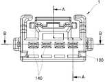
도 4는 본 발명의 일 실시예에 따른 평판 케이블 커넥터의 정면도.
도 5와 도 6은 도 4의 A-A 단면도와 B-B 단면도.
도 7 내지 도 10은 본 발명의 일 실시예에 따른 평판 케이블 커넥터의 조립과정을 도시한 도면.1 is a perspective view of a flat cable connector according to an embodiment of the present invention;
2 and 3 are exploded perspective views of a flat cable connector according to an embodiment of the present invention.
4 is a front view of a flat cable connector according to an embodiment of the present invention;
5 and 6 are sectional views taken along line AA and BB in FIG.
7 to 10 are views showing a process of assembling a flat cable connector according to an embodiment of the present invention.
첨부된 도면을 참조하여 본 발명에 따른 실시예를 상세히 설명한다. 이하, 본 발명에 따른 실시예를 설명함에 있어, 그리고 각 도면의 구성요소들에 참조부호를 부가함에 있어, 동일한 구성요소들에 대해서는 비록 다른 도면상에 표시되더라도 가능한 한 동일한 부호를 부가하였다.DETAILED DESCRIPTION OF THE PREFERRED EMBODIMENTS Referring to the accompanying drawings, embodiments of the present invention will be described in detail. DETAILED DESCRIPTION OF THE PREFERRED EMBODIMENTS Hereinafter, embodiments of the present invention will be described in detail with reference to the accompanying drawings.
도 1에 도시된 바와 같이, 통상의 평판 케이블 커넥터(1,2)는, 평판 케이블(3)의 단부에 설치되는 플러그 커넥터(1)와, 기기의 패널 등에 설치되는 리셉터클 커넥터(2)로 구성된다. 본 실시예에 따른 평판 케이블 커넥터는, 평판 케이블(3)의 단부에 설치되어 리셉터클 커넥터(2)의 내부로 삽입되는 플러그 커넥터(1)에 관한 것이다.1, a conventional
도 2 내지 도 6을 참조하여 본 실시예에 따른 평판 케이블 커넥터, 즉 플러그 커넥터(1)에 대해 살펴보면 다음과 같다.Referring to Figs. 2 to 6, the flat cable connector, i.e., the
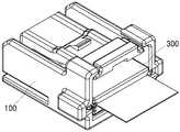
플러그 커넥터(1)는, 커넥터(1)의 외형을 이루는 외부 하우징(100)과, 리셉터클 커넥터(도 1의 2)와의 결합 시 전기적인 소통을 위한 소켓 단자(200)와, 소켓 단자(200)를 지지하는 내부 하우징(300)과, 내부 하우징(300)과 함께 평판 케이블(3)을 고정하는 제1홀더(400)와, 소켓 단자(200)의 유동을 방지하는 제2홀더(500)를 포함하여 구성된다.The
외부 하우징(100)은 전단이 폐쇄되고 후단이 개방된 파이프 형상이며, 그 내부에는 소켓 단자(200) 및 내부 하우징(300)의 설치를 위한 수용공간(110,120)이 형성된다. 수용공간(110,120)은 외부 하우징(100)의 하면에 형성된 장착공(130)을 기준으로 제1수용공간(110)과 제2수용공간(120)으로 구분된다.The
제1수용공간(110)은 장착공(130)의 전단 측에 위치되고, 수평방향으로 평행하게 배치된 다수로 구성되며, 소켓 단자(200)의 소켓(210)이 설치된다. 제2수용공간(120)은 장착공(130)의 후단 측에 위치되고, 제1수용공간(110)과 연결된 하나의 공간으로 이루어지며, 내부 하우징(300)과 제1홀더(400)가 설치된다.The
외부 하우징(100)의 전면에는 리셉터클 커넥터(도 1의 2)와의 결합 시 리셉터클 커넥터(2)의 핀 단자(미도시)가 삽입되는 다수의 삽입공(140)이 형성된다. 상기 삽입공(140)은 제1수용공간(110)과 각각 연결되어 삽입공(140)을 관통한 핀 단자(미도시)가 소켓(210)에 삽입될 수 있도록 한다.The front surface of the
외부 하우징(100)의 상면에는 리셉터클 커넥터(2)와의 잠금 또는 해정을 위한 레버(150)가 마련되고, 양측 벽면에는 내부 하우징(300)과의 결합을 위한 결합홈(160)이 형성된다.A
한편, 외부 하우징(100)의 하면에 형성된 장착공(130)은 제2홀더(500)가 설치되는 부분이다. 장착공(130)에 설치되는 제2홀더(500)는 소켓 단자(200)의 체결상태를 확인함과 동시에 소켓 단자(200)의 유동을 방지하기 위한 수단이다. 장착공(130)의 내벽에는 제2홀더(500)를 고정하기 위한 고정홈(132)이 형성되고, 제2홀더(500)에는 고정홈(132)과 대응되는 고정돌기(530)가 형성된다.The
소켓 단자(200)는, 제1수용공간(110)에 수용되는 소켓(210)과, 소켓(210)에서 후단 측으로 연장되어 제2수용공간(110)에 수용되는 단자편(220)으로 이루어진다. 소켓(210)은 핀 단자(미도시)가 삽입될 수 있도록 박스 형태를 가지며, 단자편(220)은 내부 하우징(300)의 안착홈(도 7의 312)에 수용될 수 있도록 박판의 형태로 이루어진다. 이때, 단자편(220)은 평판 케이블(3)의 접촉 단자(34)와의 접촉이 용이하도록 안착홈(312)의 깊이보다 두껍게 형성되는 것이 바람직하다.The
내부 하우징(300)은 제2수용공간(120)에 삽입 가능한 크기를 가진 판재 형상이다. 도 2와 도 7을 참조하여 내부 하우징(300)을 좀 더 상세히 살펴보면, 평판 케이블(3)의 단부가 안착되는 수평부재(310)와, 수평부재(310)의 전단을 감싸는 수직부재(320,330)로 이루어진다. 또한, 수직부재(320,330)는, 내부 하우징(300)의 전면에 위치된 전면부재(320)와, 내부 하우징(300)의 양측에 각각 위치된 한 쌍의 측면부재(330)로 이루어진다.The
수평부재(310)의 상면(도 6의 경우 상면)에는 안착홈(312)이 형성된다. 안착홈(312)은 상술한 것처럼 소켓 단자(200)의 단자편(220)이 삽입되는 부분이며, 제1수용공간(110)과 동일선 상에 각각 위치된 다수로 형성된다. 다수의 안착홈(312) 사이에는 평판 케이블(3)을 고정하는 걸림돌기(314)가 돌출된다. 이때, 걸림돌기(314)는 평판 케이블(3)을 플러그 커넥터(1)의 후방으로 당겼을 때 빠지지 않도록 직각인 면이 전방을 향하는 직각삼각형으로 형성된다.A
전면부재(320)에는 지지부재(도 5의 322)가 돌출되고, 지지부재(322)에는 관통공(324)이 형성된다. 지지부재(322)는 전면부재(320)의 전방으로 돌출되어 소켓 단자(200)의 소켓(210)을 외부 하우징(100)의 전면에 밀착시킨다. 또한, 관통공(324)은 소켓 단자(200)의 단자편(220)이 관통되는 부분이며, 관통공(324)을 관통한 단자편(220)은 안착홈(312)에 수용된다.A supporting member (322 in FIG. 5) protrudes from the
도 5에 도시된 바와 같이, 내부 하우징(300)의 지지부재(322) 하부에는 소정의 삽입공간(326)이 형성된다. 삽입공간(326)은 장착공(130)에 설치된 제2홀더(500)의 일부(즉, 잠금돌기(520))가 삽입되는 부분이다. 이 삽입공간(326)을 이용하여 소켓 단자(200)의 체결상태를 육안으로 확인할 수 있다. 예를 들어, 소켓 단자(200)의 체결상태가 정상인 경우 장착공(130)을 통해 삽입공간(326)이 노출되므로 제2홀더(500)의 설치 시 잠금돌기(520)가 삽입공간(326)으로 삽입된다. 반면, 소켓 단자(200)의 체결상태가 비정상인 경우 장착공(130)을 통해 소켓(210) 또는 전면부재(320)가 노출되므로 제2홀더(500)의 설치가 불가능하게 된다.As shown in FIG. 5, a
도 7에 도시된 것처럼, 측면부재(330)의 단부에는 외부 하우징(100)과의 결합을 위한 결합부재(340)가 형성된다. 또한, 측면부재(330)의 내벽에는 제1홀더(400)와의 결합을 위한 체결홈(350)이 형성된다. 상기 결합부재(340)는, 측면부재(330)의 단부에서 연장된 외팔보 형태의 탄성부재(342)와, 탄성부재(342)의 측면에서 돌출되며 결합홈(160)에 삽입되는 결합돌기(344)로 이루어진다.7, a
한편, 내부 하우징(300)에 고정되는 평판 케이블(3)은 통상의 평판 케이블이다. 즉, 평행하게 배치된 다수의 배선(32)을 커버(36)가 감싸고, 배선(32)의 선단에는 접촉 단자(34)가 마련되는 통상의 평판 케이블 형상이다. 이때, 다수의 배선(32) 사이에는 걸림공(38)이 형성되어 내부 하우징(300)에 안착된 평판 케이블(3)이 걸림돌기(314)에 걸려 고정될 수 있도록 한다.On the other hand, the
제1홀더(400)는 내부 하우징(300)에 삽입되어 고정될 수 있도록 판재 형상을 가진다. 내부 하우징(300)의 수평부재(310)와 대면하는 제1홀더(400)의 상면에는 걸림홈(410)이 형성된다. 또한, 제1홀더(400)의 양측 벽면에는 체결돌기(420)가 형성된다.The
상기 걸림홈(410)은 걸림돌기(314)의 일부가 삽입되는 부분으로, 걸림돌기(314)의 상부를 덮어 폐쇄함으로써 걸림돌기(314)에 걸려 고정된 평판 케이블(3)의 이탈되는 것을 확실하게 방지할 수 있다. 또한, 상기 체결돌기(420)는 제1홀더(400)를 내부 하우징(300)에 고정하는 부분으로, 내부 하우징(300)의 체결홈(350)에 삽입 가능한 형상으로 형성된다.The latching
제2홀더(500)는, 장착공(130)에 결합되는 몸체(510)와, 몸체(510)의 상부에 형성되어 삽입공간(326)으로 돌출되는 잠금돌기(520)와, 몸체(152)의 양단에 형성되어 장착공(130)의 고정홈(132)에 삽입되는 고정돌기(530)로 이루어진다.The
이러한 제2홀더(500)는 소켓 단자(200)의 체결상태를 육안으로 확인하기 위한 수단으로, 소켓 단자(200)의 체결상태가 정상인 경우 장착공(130)을 통해 삽입공간(326)으로 삽입되고, 소켓 단자(200)의 체결상태가 비정상인 경우 장착공(130)을 통해 삽입공간(326)으로 삽입되지 못한다.The
도 7 내지 도 10을 참조하여 본 실시예에 따른 플러그 커넥터(1)의 조립과정을 살펴보도록 한다.7 to 10, the assembling process of the
우선, 소켓 단자(200)를 내부 하우징(300)에 조립한다. 소켓 단자(200)의 단자편(220)은 내부 하우징(300)의 관통공(324)을 관통하여 안착홈(312)에 삽입되도록 조립한다(도 7 참조).First, the
소켓 단자(200)를 조립한 내부 하우징(300)에 평판 케이블(3)을 연결한다. 평판 케이블(3)의 접촉 단자(34)가 소켓 단자(200)의 단자편(220)에 접촉되도록, 그리고 내부 하우징(300)의 걸림돌기(314)가 평판 케이블(3)의 걸림공(38)을 관통하도록 평판 케이블(3)을 연결한다. 이때, 단자편(220)과 접촉 단자(34)를 저항 용접 등의 방법으로 접합할 경우 평판 케이블(3)의 긴장 또는 수축에 의해 접촉부(단자편(220)과 접촉 단자(34)의 접촉부)가 떨어지는 것을 방지할 수 있다.The
평판 케이블(3)의 연결이 완료되면, 도 8에 도시된 것처럼 제1홀더(400)를 내부 하우징(300)에 끼워 고정한다. 즉, 제1홀더(400)의 체결돌기(도 2의 420)가 내부 하우징(300)의 체결홈(도 7의 350)에 삽입되도록 조립한다. 내부 하우징(300)에 조립된 제1홀더(400)는 단자편(220)과 접촉 단자(34)를 밀착시켜 쇼트 등이 발생하는 것을 방지한다. 또한, 걸림홈(도 2의 410)이 걸림돌기(314)의 상부를 덮어 폐쇄함으로써 걸림돌기(314)에 걸려 고정된 평판 케이블(3)의 이탈되는 것을 확실하게 방지할 수 있다.When the connection of the
제1홀더(400)가 조립된 내부 하우징(300)의 상하를 반전시킨 후, 외부 하우징(100)의 후방에서 전방으로 밀어 넣어 조립한다(도 9 참조). 이때, 소켓 단자(200)의 소켓(210)은 제1수용공간(110)에 삽입되고, 내부 하우징(300)과 제1홀더(400)는 제2수용공간(120)에 삽입된다(도 5 참조).The
마지막으로, 외부 하우징(100)의 장착공(130)에 제2홀더(500)를 설치한다(도 10 참조). 제2홀더(500)는 소켓 단자(200)의 체결상태를 확인함과 동시에 소켓 단자(200)의 유동을 방지하기 위한 수단이다. 즉, 소켓 단자(200)의 체결상태가 정상인 경우 장착공(130)을 통해 삽입공간(326)이 노출되므로 제2홀더(500)의 설치 시 잠금돌기(520)가 삽입공간(326)으로 삽입된다. 반면, 소켓 단자(200)의 체결상태가 비정상인 경우 장착공(130)을 통해 소켓(210) 또는 전면부재(320)가 노출되므로 제2홀더(500)의 설치가 불가능하게 된다(도 5 참조).Finally, the
장착공(130)에 설치된 제2홀더(500)는 고정돌기(530)와 고정홈(132)에 의해 외부 하우징(100)에 고정된다.The
이상 본 발명을 바람직한 실시예를 통하여 설명하였는데, 상술한 실시예는 본 발명의 기술적 사상을 예시적으로 설명한 것에 불과하며, 본 발명의 기술적 사상을 벗어나지 않는 범위 내에서 다양한 변화가 가능함은 이 분야에서 통상의 지식을 가진 자라면 이해할 수 있을 것이다. 따라서 본 발명의 보호범위는 특정 실시예가 아니라 특허청구범위에 기재된 사항에 의해 해석되어야 하며, 그와 동등한 범위 내에 있는 모든 기술적 사상도 본 발명의 권리범위에 포함되는 것으로 해석되어야 할 것이다.
While the present invention has been particularly shown and described with reference to preferred embodiments thereof, it is to be understood that the invention is not limited to the disclosed embodiments, but, on the contrary, is intended to cover various modifications and equivalent arrangements included within the spirit and scope of the appended claims. Those skilled in the art will understand. Therefore, the scope of protection of the present invention should be construed not only in the specific embodiments but also in the scope of claims, and all technical ideas within the scope of the same shall be construed as being included in the scope of the present invention.
1: 플러그 커넥터2: 리셉터클 커넥터
3: 평판 케이블100: 외부 하우징
200: 소켓 단자300: 내부 하우징
400: 제1홀더500: 제2홀더1: Plug connector 2: Receptacle connector
3: Flat cable 100: Outer housing
200: socket terminal 300: inner housing
400: first holder 500: second holder
Claims (10)
Translated fromKorean상기 수용공간에 수용된 소켓과, 상기 소켓에서 연장된 단자편으로 이루어진 소켓 단자;
상기 단자편을 설치하기 위한 안착홈이 형성되고, 상기 안착홈 사이에 걸림돌기가 마련되며, 상기 수용공간에 삽입되어 상기 소켓 단자를 상기 외부 하우징에 밀착시키는 내부 하우징;
배선의 선단에 접촉 단자가 마련되고, 배선을 감싸는 커버에 걸림공이 천공되며, 상기 걸림공이 상기 걸림돌기에 걸리도록 상기 내부 하우징에 안착되는 평판 케이블; 및
상기 내부 하우징에 결합되어 상기 접촉 단자를 상기 단자편에 접촉되도록 가압하는 제1홀더를 포함하고,
상기 제1홀더에는 상기 걸림돌기가 삽입되는 걸림홈이 형성되며,
상기 수용공간은, 상기 소켓이 수용되는 제1수용공간과, 상기 내부 하우징이 삽입되는 제2수용공간으로 구획되되, 상기 제1수용공간이 평행하게 배치된 다수로 이루어지고,
상기 내부 하우징은, 상기 안착홈이 일면에 형성된 수평부재와, 상기 수평부재의 일면 둘레를 감싸는 수직부재로 이루어지되, 상기 수직부재의 양측 내벽에는 체결홈이 형성되고, 상기 제1홀더의 양측에는 체결돌기가 형성되며,
상기 수직부재의 양단에는 탄성 변형이 가능한 결합부재가 형성되고, 상기 외부 하우징의 양측 내벽에는 상기 결합부재의 적어도 일부가 삽입되는 결합홈이 형성되며,
상기 결합부재는, 상기 수직부재의 양단에서 연장된 외팔보 형태의 탄성부재와, 상기 탄성부재의 측면에서 돌출되어 상기 결합홈에 삽입되는 결합돌기로 이루어지고,
상기 수직부재의 전면에는 상기 단자편이 관통되는 관통공이 형성되고, 상기 수직부재의 전면에는 상기 소켓 단자에 접촉되는 지지부재가 돌출되며, 상기 소켓과 상기 수직부재 사이에 삽입공간이 마련되며,
상기 외부 하우징의 일면에는 장착공이 형성되고, 상기 장착공에는 상기 소켓 단자의 체결상태를 확인함과 동시에 유동을 방지하기 위한 제2홀더가 설치되며, 상기 제2홀더는 그 일부가 상기 수용공간 측으로 돌출되어 상기 삽입공간에 삽입되고,
상기 제2홀더는, 상기 장착공에 결합되는 몸체와, 상기 삽입공간으로 돌출된 잠금돌기로 이루어진 것을 특징으로 하는 평판 케이블 커넥터.
An outer housing in which a front end is closed and a rear end is opened, a pin terminal insertion hole is formed on the front surface, and an accommodation space is provided inside;
A socket terminal accommodated in the accommodating space, the socket terminal comprising a terminal piece extending from the socket;
An inner housing formed with a seating groove for mounting the terminal piece, a locking protrusion provided between the seating recesses and inserted into the accommodation space to closely contact the socket terminal with the outer housing;
A flat cable provided with a contact terminal at the tip of the wiring, a latching hole formed in the cover for covering the wiring, and the latching hole being seated on the latching protrusion; And
And a first holder coupled to the inner housing and pressing the contact terminal to contact the terminal piece,
Wherein the first holder is formed with a latching groove into which the latching protrusion is inserted,
Wherein the accommodating space is divided into a first accommodating space in which the socket is accommodated and a second accommodating space in which the internal housing is inserted,
Wherein the inner housing comprises a horizontal member formed on one side of the seating groove and a vertical member surrounding one side of the horizontal member, wherein fastening grooves are formed on both inner walls of the vertical member, A fastening protrusion is formed,
Wherein both ends of the vertical member are formed with an engaging member capable of resilient deformation, and both side walls of the outer housing are formed with engaging grooves into which at least a part of the engaging member is inserted,
Wherein the engaging member includes an elastic member in the form of a cantilever extending from both ends of the vertical member and an engaging protrusion protruded from a side surface of the elastic member and inserted into the engaging groove,
A support member contacting the socket terminal is protruded on a front surface of the vertical member and an insertion space is provided between the socket and the vertical member,
A mounting hole is formed on one surface of the outer housing, a second holder for confirming the fastening state of the socket terminal and preventing the flow of the socket terminal is installed in the mounting hole, and a part of the second holder is connected to the receiving space side Protruding into the insertion space,
Wherein the second holder comprises a body coupled to the mounting hole, and a locking protrusion protruding from the insertion space.
상기 장착공과 상기 제2홀더 중 어느 하나에는 고정돌기가 형성되고, 다른 하나에는 고정홈이 형성된 것을 특징으로 하는 평판 케이블 커넥터.The method of claim 9,
Wherein a fixing protrusion is formed on one of the mounting hole and the second holder and a fixing groove is formed on the other of the mounting hole and the second holder.
Priority Applications (1)
| Application Number | Priority Date | Filing Date | Title |
|---|---|---|---|
| KR1020140065017AKR101562810B1 (en) | 2014-05-29 | 2014-05-29 | Flat cable connector |
Applications Claiming Priority (1)
| Application Number | Priority Date | Filing Date | Title |
|---|---|---|---|
| KR1020140065017AKR101562810B1 (en) | 2014-05-29 | 2014-05-29 | Flat cable connector |
Publications (1)
| Publication Number | Publication Date |
|---|---|
| KR101562810B1true KR101562810B1 (en) | 2015-11-09 |
Family
ID=54605062
Family Applications (1)
| Application Number | Title | Priority Date | Filing Date |
|---|---|---|---|
| KR1020140065017AActiveKR101562810B1 (en) | 2014-05-29 | 2014-05-29 | Flat cable connector |
Country Status (1)
| Country | Link |
|---|---|
| KR (1) | KR101562810B1 (en) |
Cited By (4)
| Publication number | Priority date | Publication date | Assignee | Title |
|---|---|---|---|---|
| KR20180107531A (en)* | 2017-03-22 | 2018-10-02 | (주)우주일렉트로닉스 | Electrical connecting structure for flat cable |
| KR20180116892A (en)* | 2017-04-18 | 2018-10-26 | (주)우주일렉트로닉스 | Electrical connecting structure for flat cable for improving contact reliablility |
| KR20190036188A (en)* | 2017-09-27 | 2019-04-04 | 한국단자공업 주식회사 | Connector |
| WO2019240378A1 (en)* | 2018-06-12 | 2019-12-19 | 주식회사 엘지화학 | Pcb direct connector having two-row terminal structure |
Citations (3)
| Publication number | Priority date | Publication date | Assignee | Title |
|---|---|---|---|---|
| JP2002203632A (en) | 2000-12-27 | 2002-07-19 | Fujikura Ltd | How to accommodate connectors and connection terminals |
| JP2011253619A (en) | 2010-03-31 | 2011-12-15 | Fujikura Ltd | Waterproof connector |
| JP2013051080A (en) | 2011-08-30 | 2013-03-14 | Yazaki Corp | Connector |
- 2014
- 2014-05-29KRKR1020140065017Apatent/KR101562810B1/enactiveActive
Patent Citations (3)
| Publication number | Priority date | Publication date | Assignee | Title |
|---|---|---|---|---|
| JP2002203632A (en) | 2000-12-27 | 2002-07-19 | Fujikura Ltd | How to accommodate connectors and connection terminals |
| JP2011253619A (en) | 2010-03-31 | 2011-12-15 | Fujikura Ltd | Waterproof connector |
| JP2013051080A (en) | 2011-08-30 | 2013-03-14 | Yazaki Corp | Connector |
Cited By (8)
| Publication number | Priority date | Publication date | Assignee | Title |
|---|---|---|---|---|
| KR20180107531A (en)* | 2017-03-22 | 2018-10-02 | (주)우주일렉트로닉스 | Electrical connecting structure for flat cable |
| KR102008694B1 (en)* | 2017-03-22 | 2019-10-21 | (주)우주일렉트로닉스 | Electrical connecting structure for flat cable |
| KR20180116892A (en)* | 2017-04-18 | 2018-10-26 | (주)우주일렉트로닉스 | Electrical connecting structure for flat cable for improving contact reliablility |
| KR102028425B1 (en)* | 2017-04-18 | 2019-10-04 | (주)우주일렉트로닉스 | Electrical connecting structure for flat cable for improving contact reliablility |
| KR20190036188A (en)* | 2017-09-27 | 2019-04-04 | 한국단자공업 주식회사 | Connector |
| KR102366146B1 (en) | 2017-09-27 | 2022-02-23 | 한국단자공업 주식회사 | Connector |
| WO2019240378A1 (en)* | 2018-06-12 | 2019-12-19 | 주식회사 엘지화학 | Pcb direct connector having two-row terminal structure |
| US11114788B2 (en) | 2018-06-12 | 2021-09-07 | Lg Chem, Ltd. | PCB direct connector having two-row terminal structure |
Similar Documents
| Publication | Publication Date | Title |
|---|---|---|
| JP5563241B2 (en) | Electrical connector | |
| CN102282732B (en) | Grounding connector and wiring harness including the grounding connector | |
| JP5301725B2 (en) | Female connector assembly | |
| CN104505642B (en) | Plug electric connector | |
| CN102640363B (en) | Plug and socket connector arrangement with first and second plugs and mating plugs | |
| CN107732482B (en) | Cable connector assembly with branching element | |
| EP2304853B1 (en) | High density rectangular interconnect | |
| US11251560B2 (en) | Terminal position assurance member with multiple latches | |
| KR101562810B1 (en) | Flat cable connector | |
| CN107710517A (en) | Joint connector | |
| KR102550876B1 (en) | Connector for coaxial cable | |
| JP2006510169A (en) | Electrical connector with terminal position maintenance system | |
| US20060141867A1 (en) | Cable assembly with improved engaging means | |
| JP2019079620A (en) | Shield connector and shield connector system | |
| CN206148720U (en) | Plug connector and cable connector with the plug connector | |
| CN106887726B (en) | Clamping devices, electrical connectors and connector assemblies | |
| CN114824903B (en) | Cable connector assembly | |
| US7731519B1 (en) | Adaptable universal electrical connector system particularly adapted for use in repair or replacement of electrical components such as relays, solenoids and the like | |
| CN204927572U (en) | Electric connector with flat cable | |
| KR101651653B1 (en) | Wire to wire connector assembly | |
| US20170170599A1 (en) | Connector | |
| JP7282449B2 (en) | plugs and receptacles | |
| KR20180085095A (en) | Connecter equipped with snap type earth structure | |
| KR101292571B1 (en) | Connector and connector assembly having the same | |
| KR20150027406A (en) | A connector assembly |
Legal Events
| Date | Code | Title | Description |
|---|---|---|---|
| PA0109 | Patent application | Patent event code:PA01091R01D Comment text:Patent Application Patent event date:20140529 | |
| PA0201 | Request for examination | ||
| PE0902 | Notice of grounds for rejection | Comment text:Notification of reason for refusal Patent event date:20150320 Patent event code:PE09021S01D | |
| PE0701 | Decision of registration | Patent event code:PE07011S01D Comment text:Decision to Grant Registration Patent event date:20150828 | |
| GRNT | Written decision to grant | ||
| PR0701 | Registration of establishment | Comment text:Registration of Establishment Patent event date:20151019 Patent event code:PR07011E01D | |
| PR1002 | Payment of registration fee | Payment date:20151020 End annual number:3 Start annual number:1 | |
| PG1601 | Publication of registration | ||
| FPAY | Annual fee payment | Payment date:20180905 Year of fee payment:4 | |
| PR1001 | Payment of annual fee | Payment date:20180905 Start annual number:4 End annual number:4 | |
| FPAY | Annual fee payment | Payment date:20191001 Year of fee payment:5 | |
| PR1001 | Payment of annual fee | Payment date:20191001 Start annual number:5 End annual number:5 | |
| PR1001 | Payment of annual fee | Payment date:20201006 Start annual number:6 End annual number:6 | |
| PR1001 | Payment of annual fee | Payment date:20210915 Start annual number:7 End annual number:7 | |
| PR1001 | Payment of annual fee | Payment date:20220907 Start annual number:8 End annual number:8 | |
| PR1001 | Payment of annual fee | Payment date:20240905 Start annual number:10 End annual number:10 |