KR101559885B1 - Power over ethernet on data pairs and spare pairs - Google Patents
Power over ethernet on data pairs and spare pairsDownload PDFInfo
- Publication number
- KR101559885B1 KR101559885B1KR1020140073521AKR20140073521AKR101559885B1KR 101559885 B1KR101559885 B1KR 101559885B1KR 1020140073521 AKR1020140073521 AKR 1020140073521AKR 20140073521 AKR20140073521 AKR 20140073521AKR 101559885 B1KR101559885 B1KR 101559885B1
- Authority
- KR
- South Korea
- Prior art keywords
- wire pair
- switch
- poe
- pair
- spare
- Prior art date
- Legal status (The legal status is an assumption and is not a legal conclusion. Google has not performed a legal analysis and makes no representation as to the accuracy of the status listed.)
- Active
Links
Images


Classifications
- H—ELECTRICITY
- H04—ELECTRIC COMMUNICATION TECHNIQUE
- H04L—TRANSMISSION OF DIGITAL INFORMATION, e.g. TELEGRAPHIC COMMUNICATION
- H04L12/00—Data switching networks
- H04L12/02—Details
- H04L12/10—Current supply arrangements
- G—PHYSICS
- G06—COMPUTING OR CALCULATING; COUNTING
- G06F—ELECTRIC DIGITAL DATA PROCESSING
- G06F1/00—Details not covered by groups G06F3/00 - G06F13/00 and G06F21/00
- G06F1/26—Power supply means, e.g. regulation thereof
- G—PHYSICS
- G06—COMPUTING OR CALCULATING; COUNTING
- G06F—ELECTRIC DIGITAL DATA PROCESSING
- G06F1/00—Details not covered by groups G06F3/00 - G06F13/00 and G06F21/00
- G06F1/26—Power supply means, e.g. regulation thereof
- G06F1/266—Arrangements to supply power to external peripherals either directly from the computer or under computer control, e.g. supply of power through the communication port, computer controlled power-strips
- H—ELECTRICITY
- H04—ELECTRIC COMMUNICATION TECHNIQUE
- H04L—TRANSMISSION OF DIGITAL INFORMATION, e.g. TELEGRAPHIC COMMUNICATION
- H04L12/00—Data switching networks
- H04L12/28—Data switching networks characterised by path configuration, e.g. LAN [Local Area Networks] or WAN [Wide Area Networks]
- H04L12/40—Bus networks
- H04L12/40006—Architecture of a communication node
- H04L12/40045—Details regarding the feeding of energy to the node from the bus
- H—ELECTRICITY
- H04—ELECTRIC COMMUNICATION TECHNIQUE
- H04L—TRANSMISSION OF DIGITAL INFORMATION, e.g. TELEGRAPHIC COMMUNICATION
- H04L25/00—Baseband systems
- H04L25/02—Details ; arrangements for supplying electrical power along data transmission lines
- H04L25/0264—Arrangements for coupling to transmission lines
- H04L25/0272—Arrangements for coupling to multiple lines, e.g. for differential transmission
- H—ELECTRICITY
- H04—ELECTRIC COMMUNICATION TECHNIQUE
- H04L—TRANSMISSION OF DIGITAL INFORMATION, e.g. TELEGRAPHIC COMMUNICATION
- H04L49/00—Packet switching elements
- H04L49/40—Constructional details, e.g. power supply, mechanical construction or backplane
Landscapes
- Engineering & Computer Science (AREA)
- Theoretical Computer Science (AREA)
- Computer Networks & Wireless Communication (AREA)
- Signal Processing (AREA)
- General Engineering & Computer Science (AREA)
- Physics & Mathematics (AREA)
- General Physics & Mathematics (AREA)
- Computer Hardware Design (AREA)
- Power Engineering (AREA)
- Small-Scale Networks (AREA)
- Power Sources (AREA)
Abstract
Translated fromKorean
Description
Translated fromKorean본 발명은 제프리 린 헬스 등(Jaffrey Lynn Heath et al.)에 의해 2013년 6월 18일자로 출원된 미국가출원 일련번호 제61/836,399호에 기초하며 그로부터 우선권을 주장하고, 상기 가출원은 여기에 참조로 통합된다.The present invention is based on and claims priority from U.S. Serial No. 61 / 836,399, filed June 18, 2013 by Jaffrey Lynn Heath et al., Which claims priority from, Lt; / RTI >
본 발명은 트위스트 데이터 와이어 쌍과 트위스트 스페어 와이어 쌍을 통하여 전력이 전송되는 PoE(Power Over Ethernet) 시스템에 관한 것이다.The present invention relates to a PoE (Power Over Ethernet) system in which power is transmitted through a pair of twisted data wires and twisted spare wires.
원격 장비에 전력을 공급하기 위하여 데이터 라인을 통하여 전력을 공급하는 것이 공지되어 있다. PoE는 그러한 시스템의 일예이다. PoE에서는 이더넷 스위치로부터 이더넷-연결 장비(예컨대, VoIP 전화, WLAN 전송기, 보안 카메라 등)로 제한된 전력이 전송된다. 통상, 스위치로부터의 DC 전력은 표준 CAT-5 케이블링에서 두 세트의 트위스트 쌍 와이어들을 통하여 전송된다. DC 공통 모드 전압은 데이터에 영향을 주지 않기 때문에 동일한 두 세트의 트위스트 쌍 와이어들은 차분 데이터 신호 또한 전송할 수 있다. 이러한 방식으로, "전력 장치들(Powered Devices)"(PDs)에 임의의 외부 전원을 제공할 필요성이 제거될 수 있다. PoE 표준은 본 명세서에 참조로 통합된 IEEE 802.3에 개시된다.It is known to supply power through a data line to power remote equipment. PoE is an example of such a system. In PoE, limited power is transmitted from the Ethernet switch to Ethernet-connected equipment (e.g., VoIP phones, WLAN transmitters, security cameras, etc.). Typically, DC power from the switch is transmitted through two sets of twisted pair wires in standard CAT-5 cabling. Because the DC common mode voltage does not affect the data, the same two sets of twisted pair wires can also transmit the differential data signal. In this way, the need to provide any external power to "Powered Devices" (PDs) can be eliminated. The PoE standard is disclosed in IEEE 802.3, which is incorporated herein by reference.
이더넷 표준은 데이터 쌍으로 지정된 제1 및 제2 쌍의 트위스트 와이어들 및 스페어 쌍으로 지정된 제3 및 제4 쌍의 트위스트 와이어들을 특정한다. 스페어 쌍들은 통상 25.5W의 IEEE 전력 제한보다 많은 전력을 요구하지 않는 PD들에는 사용되지 않는다. "PSE(Power Sourcing Equipment)"는 데이터 라인을 통하여 PD에 전력을 공급하는 임의의 이더넷 장치일 수 있다. PSE 및 PD는 통상 표준 이더넷 8-핀(네 개의 트위스트 쌍) 커넥터로 종결되는 표준 CAT-5 케이블을 통하여 연결된다.The Ethernet standard specifies the first and second pairs of twisted wires designated as data pairs and the third and fourth pairs of twisted wires designated as a spare pair. Spare pairs are not used for PDs that typically do not require more power than the IEEE power limit of 25.5W. "Power Sourcing Equipment " (PSE) may be any Ethernet device that powers a PD through a data line. The PSE and PD are typically connected via standard CAT-5 cables terminated with standard Ethernet 8-pin (four twisted pair) connectors.
그러나, 25.5W IEEE 제한보다 많은 전력을 요구하는 PD들이 존재하는 것이 공지되어 있다. CAT-5 케이블을 따른 PoE 전력 손실을 최소화하기 위하여, 케이블에서의 저항 손실을 감소시키도록 PSE 종단과 PD 종단 모두에 데이터 쌍과 스페어 쌍을 병렬로 연결하는 것이 공지되어 있다. 이는 도 1에 도시된다.However, it is known that there are PDs that require more power than the 25.5W IEEE limit. To minimize PoE power loss along CAT-5 cables, it is known to couple data pairs and spare pairs in parallel at both the PSE termination and the PD termination to reduce the resistance loss in the cable. This is shown in FIG.
도 1은 두 개의 경로를 따라 PoE 전류를 병렬로 전달하기 위하여 CAT-5 케이블의 데이터 쌍들(12 및 13)이 PSE(18)의 스페어 쌍들(14 및 15)에 고정-배선된 PoE를 이용한 이더넷 시스템을 나타낸다. 이는 현재 PoE에 대한 IEEE 표준을 위반하는 것이지만, 다양한 사용자들에 의해 행해지고 있다. "PoE"라는 용어는 종종 IEEE 표준에 따른 시스템을 식별하기 위하여 사용되기 때문에, 도 1의 시스템은 ">25.5W PoE"이라 할 수 있다. 이 쌍들은 접지 및 PD 제어장치(24)의 VIN 단자에 전류를 결합시키기 위하여 PD(22)의 개별 다이오드 브리지들(20 및 21)에 적용된다. PoE 공급 전압이 -55V로 도시되고 있지만, 공급 전압은 시스템에 따라 다른 값일 수 있다. 각 세트의 쌍들이 25.5W의 전력을 반송(carry)하는 것이 보장되기 때문에, 쌍들의 결합은 PD(22)가 필요로 하고 IR 강하를 감소시킨다면 더 높은 전력을 안전하게 반송할 수 있다.Figure 1 illustrates that
PSE(18)는 통상 주 전압(120VAC)에 의해 전력이 공급되고 44 내지 57 볼트 사이의 DC 전압을 생성하기 위하여 외부 또는 내부 전압 변환기를 사용한다. PoE 표준은 PoE가 PD에 최소 37볼트를 공급할 것을 요구한다. 케이블에 따른 전압 강하는 거리에 따라 증가한다.The
사용 중인 모든 쌍들은 변압기 23 및 25와 같은 변압기들에 의해 PD(22)에서 종결된다. 트위스트 쌍들 13 및 15가 44 볼트를 제공하고 트위스트 쌍들 12 및 14가 접지에 연결된다고 가정된다. PD 제어장치(24)로 약 44 볼트를 제공하기 위하여 변압기들의 중심 탭으로의 연결이 이루어진다. DC 전압은 공통 모드이기 때문에 차분 데이터에 영향을 주지 않는다.All pairs in use are terminated at the
전압을 PD 부하에 의해 요구되는 임의의 전압으로 변환하기 위하여 44 볼트가 DC-DC 변환기(26)에 적용된다. 변환기(26)에 의해 부하(예컨대, 보안 카메라)에 전력이 공급되고, 부하는 트위스트 와이어 쌍들을 통하여 PSE(18) 및 임의의 다른 장비들과 통신할 수 있다.44 volts is applied to the DC-
PoE-전력 장치의 존재를 검출하고 PSE(18)가 PD(22)에 이용가능한 풀 전력을 제공하기 전에 PSE(18)와 PD(22)의 관련 특성들을 전달하기 위하여, IEEE 표준은 PSE(18)와 PD(22) 사이의 특정 저전력 핸드셰이킹(handshaking) 과정을 요구한다.In order to detect the presence of a PoE-power device and to communicate the relevant characteristics of the
이하는 PSE(18)와 PD(22) 사이의 표준 핸드셰이킹 프로토콜의 간략화된 요약이다.The following is a simplified summary of the standard handshaking protocol between the
PoE-인에이블 이더넷 케이블이 PD(22)에 플러그인되면, PSE 제어장치(27)는 그것이 PoE-호환가능한지를 결정하기 위하여 PD(22)에 질의한다. 이 구간을 검출 단계라 한다. 검출 단계 동안, PSE 제어장치(27)는 트위스트 와이어 쌍들(12 및 13)을 통하여 PD(22)에 고정된 간격으로 제1 전압-제한 전류를 인가하고 다음으로 결과 전압을 검출하는 것에 의해 (약 25K 옴인) PD(22)의 특성 임피던스를 구하면서 고정된 간격으로 제2 전압-제한 전류를 인가한다. 정확한 임피던스가 검출되지 않으면, PSE(18)는 부하가 PoE-호환가능하지 않고 PoE 기능을 사용할 수 없다고 추측한다. 다음으로 시스템은 표준 이더넷 연결로 동작한다.Once the PoE-enabled Ethernet cable is plugged into the
시그니처 임피던스가 검출되면, PSE 제어장치(27)는 선택적 분류 단계로 이동한다. PSE 제어장치(27)는 PD(22)로의 전압을 증가시킨다. PSE 제어장치(27)는 (Type 1 PSE임을 가리키는) 1개의 펄스 또는 (Type 2 PSE임을 가리키는) 두개의 펄스를 발생시킨다. PD(22)는 PD(22)가 Type 1인지 Type 2인지를 식별하기 위하여 특정 전류 레벨을 가지는 분류 펄스에 응답한다. Type 1 PD는 13W 보다 적은 전력을 요구한다. Type 2 PD는 최대 25.5W를 요구한다. 이러한 유형들 내에 각각 최대 평균 전류 레벨 및 최대 순간 전류 레벨과 연관된 다양한 분류들(예컨대, 5개의 분류)이 또한 식별될 수 있다. 도 1에 도시된 바와 같이 PD 제어장치(24)의 RCLASS 핀에 연결된 분류 저항이 사용될 수 있다. 다음으로 PSE 제어장치(27)는 PD(22)에 요구되는 전력을 공급할 수 있는지를 결정하기 위하여 이러한 전력 요구 정보를 사용할 수 있으며, PD(22)는 PSE(18)로 완전히 동작할 수 있는지를 결정하기 위하여 이 정보를 사용한다. 검출 및 분류 단계를 위한 최대 시간 윈도우들(예컨대, 500ms)이 존재한다.When the signature impedance is detected, the
더 높은 전력 장비에 대하여, PSE(18)가 PD(22)로 25.5W 초과의 전력을 제공할 수 있게 하는 고전력 분류가 지정된다. 그러한 고전력 분류에서는, 전류를 공유하기 위하여 데이터 쌍들 및 스페어 쌍들이 묶이는 것이 바람직하다.For higher power equipment, a high power classification is specified that allows the
다른 유형의 검출 및 분류 루틴 및 표준들이 추후 구현될 수 있다.Other types of detection and classification routines and standards may be implemented later.
검출 및 분류 단계가 완료되면, PSE 제어장치(27)는 PoE 출력 전압을 42V보다 높게 증가시키고, FET(30)는 PD(22)로 전체 PoE 전압을 직접 연결시키도록 닫힌다. UVLO(under-voltage lockout) 임계값이 PD(22)에서 검출되면, 내부 FET은 DC-DC 변환기(26)를 활성화시키기 위한 "POWER GOOD" 신호를 생성하기 위하여 턴온된다. 이 때, PD(22)는 정상으로 동작하기 시작하며, 입력 전압이 요구 레벨보다 높게 유지되는 한 계속하여 정상으로 동작한다.When the detection and classification step is completed, the
낮은 값 검지 저항(32)이 전류 경로에 직렬로 연결되고 그것의 전압 강하가 PSE 제어장치(27)에 의해 검출된다. PSE 제어장치(27)는 1) PD(22)가 연결해제되었는지를 검출하고; 2) 보고를 위하여 검지 저항을 통한 실제 전류를 검출하며; 3) 보고를 위하여 과전류 상황을 검출하고; 4) PD(22)가 FET(30)을 통한 전류를 제한하는 기계적-정지 전류 제한에 도달했는지 여부를 검출하기 위하여 검치된 신호를 이용한다. 전류 플래그는 PD(22)의 분류에 의존한다. PD(22)로의 전력공급을 중단할 것이 요구되면 PSE 제어장치(27)는 FET(30)을 턴오프한다.The low value detecting resistor 32 is connected in series to the current path and its voltage drop is detected by the
데이터는 다른 장치의 트랜시버를 데이터 쌍들의 변압기 및 스페어 쌍들의 변압기의 차분 단자에 연결하는 것과 같이 종래 수단을 사용하여 데이터 쌍들 및 스페어 쌍들을 통하여 전송될 수 있다.The data may be transmitted over data pairs and spare pairs using conventional means such as connecting the transceiver of the other device to the differential terminal of the transformer of the data pairs and the spare pairs of the spare pairs.
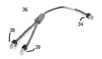
PSE(18)의 설계자가 무슨 장치들이 PSE(18)에 연결되는지를 관리하지 않을 수 있기 때문에, PSE(18)는 사용자에 의해 부정확하게 사용될 수 있으며, 이는 장비의 손상을 가져온다. 도 2는 장비의 손상을 가져올 수 있는 하나의 가능한 구성을 도시한다.Since the designer of the
도 2에서, 사용자는 도 3에 도시된 Y-케이블(36)의 일단(34)을 PSE(18)의 8-핀 CAT-5 소켓에 연결하기로 결정한다. Y-케이블(36)의 타단은 데이터 쌍들 단부(38) 및 스페어 쌍들 단부(39)로 분리된다. 단부(39)는 이 예에서 임의로 선택된 장치인 네트워크 인터페이스 제어장치(NIC)(42)의 CAT-5 소켓에 연결되는 것으로 도시된다. NIC(42)는 PoE를 사용하도록 구성되지 않는다. 그러나, PD(22)는 검출 및 분류 단계 동안 PSE(18)가 데이터 쌍들 및 스페어 쌍들 상에 44 볼트를 제공해야 함를 가리킨다. 따라서, NIC(42)는 손상될 수 있으며/있거나 시스템은 상승된 플래그에 의해 셧다운될 것이다.In Figure 2, the user decides to connect one
그러한 문제는 각 장치 상에 독립된 검출 및 분류 루틴이 수행되도록 PD(22) 및 NIC(42)(또는 임의의 다른 장비)에 개별 PSE 및 CAT-5 케이블을 제공하는 것에 의해 방지될 수 있으나, 그러한 구성은 시스템에 대한 비용 및 크기를 증가시킨다.Such a problem may be prevented by providing separate PSE and CAT-5 cables to the
필요한 것은 1) 데이터 쌍들과 스페어 쌍들 모두에 동일하게 전력을 공급할 수 있거나; 2) 데이터 쌍에만 전력을 공급하거나; 3) 어느 한 쌍에 PoE를 제공하지 않을 수 있는 PoE 시스템 내의 단일 PSE 제어장치이다. 여기서, PSE 제어장치는 데이터 쌍들 또는 스페어 쌍들 중 하나에 연결된 비-PoE 호환가능 장치에 PoE 전압이 공급되지 않을 것을 보장한다.What is needed is 1) it can equally power both data pairs and spare pairs; 2) supply power only to the data pair; 3) a single PSE controller in a PoE system that may not provide PoE to any pair. Here, the PSE controller ensures that the PoE voltage is not supplied to the non-PoE compatible devices connected to either the data pairs or the spare pairs.
두 개의 독립적으로 제어가능한 출력 포트를 구비하는 PSE 제어장치가 개시되며, 제1 출력 포트(OUT1)는 데이터 쌍들에 연결되고 제2 출력 포트(OUT2)는 공통 접지를 가지는 스페어 쌍들에 연결된다. 제1 FET는 검출 및 분류 단계 후에 정상 동작 동안 전체 PoE 전압을 데이터 쌍들에 와이어택적으로 연결한다. 검출 및 분류 단계 전에, PSE 제어장치는 데이터 쌍들을 스페어 쌍들로부터 격리시키고 또한 OUT1을 OUT2로부터 격리시키기 위하여 제2 FET(또는 다른 유형의 스위치)을 제어한다. PSE 제어장치는 OUT1 및 OUT2를 사용하여 데이터 쌍들 및 스페어 쌍들을 통하여 검출 및 분류를 독립적으로 및/또는 동시에 수행할 수 있다.A PSE controller with two independently controllable output ports is disclosed in which a first output port OUT1 is connected to data pairs and a second output port OUT2 is connected to spare pairs having a common ground. The first FET wire-selectively connects the entire PoE voltage to data pairs during normal operation after the detection and classification step. Before the detection and classification step, the PSE controller controls the second FET (or other type of switch) to isolate the data pairs from the spare pairs and also isolate OUT1 from OUT2. The PSE controller can perform detection and classification independently and / or concurrently through data pairs and spare pairs using OUT1 and OUT2.
검출 및 분류 단계의 결과가 PoE가 데이터 쌍들에만 공급되고 스페어 쌍들에는 공급되지 않아야 함을 나타내면, 데이터 쌍들이 스페어 쌍들로부터 격리되어 있으며 PoE 전압이 데이터 쌍들에만 제공되도록 제2 FET은 오프가 유지된다. 두 쌍들은 종래의 수단을 통해 데이터를 여전히 전송/수신할 수 있다.If the result of the detection and classification step indicates that PoE should be supplied only to the data pairs and not to the spare pairs, the second FET is kept off such that the data pairs are isolated from the spare pairs and the PoE voltage is only provided to the data pairs. The two pairs can still transmit / receive data via conventional means.
검출 및 분류 단계가 단일 PD가 데이터 쌍들 및 스페어 쌍들 모두에 연결되어 있음을 나타내고, PD가 (>25.5W를 요구하는) 고전력 PD로 분류되면, 제2 FET은 데이터 쌍들을 스페어 쌍들에 연결하도록 턴온되며, PoE 전압은 저항성 손실을 감소시키기 위하여 전력이 두 세트의 쌍들에 의해 동일하게 공유되도록 쌍들의 세트 모두에 적용된다.The detection and classification step indicates that a single PD is coupled to both data pairs and spare pairs, and if the PD is classified as a high power PD (requiring> 25.5W), the second FET is turned on to couple the data pairs to the spare pairs And the PoE voltage is applied to both sets of pairs such that the power is equally shared by the two sets of pairs to reduce the resistive loss.
PoE에 대한 현재 IEEE 표준은 데이터 쌍들 및 스페어 쌍들이 두 세트의 쌍들을 통하여 PoE를 공급하기 위하여 단락되는 것을 방지하나; 본 발명은 데이터 쌍들 및 스페어 쌍들에 두 세트의 쌍들을 통하여 PoE 전압을 공급하기 위하여 제2 FET이 함께 단락되는 것을 가능하게 한다. PoE의 IEEE 표준은 그러한 시나리오를 포함하도록 추후 변경될 수 있다.The current IEEE standard for PoE prevents data pairs and spare pairs from being shorted to supply PoE through two sets of pairs; The present invention enables the second FET to be shorted together to supply the PoE voltage through pairs of two sets of data pairs and spare pairs. The IEEE standard of PoE may be changed later to include such scenarios.
검출 및 분류 단계가 단일 PD가 데이터 쌍들 및 스페어 쌍들 모두에 연결되고, PD가 (<25.5W를 요구하는) 표준 전력 PD로 분류됨을 나타내면, 제2 FET은 데이터 쌍들을 스페어 쌍들에 연결하도록 턴온될 수 있으며, 따라서 전력은 두 세트의 쌍들에 의해 동일하게 공유된다. 그러나, IEEE 표준을 만족할 것이 요구되면, 제2 FET은 오프로 유지되어야 한다.If the detection and classification step indicates that a single PD is connected to both data pairs and spare pairs and that the PD is classified as a standard power PD (requiring <25.5 W), then the second FET is turned on to couple the data pairs to the spare pairs And therefore the power is shared equally by the two sets of pairs. However, if it is required to satisfy the IEEE standard, the second FET must be kept off.
검출 및 분류 단계가 PoE 요구사항이 데이터 쌍들 및 스페어 쌍들에 연결된 서로 다른 PD들에 대하여 동일함을 나타내거나, PD들이 호환가능한 분류를 가진다면, 제2 FET은 PoE 전압이 데이터 쌍들 및 스페어 쌍들에 제공되도록 하기 위하여, 현재 IEEE 표준을 위반하여, 턴온될 수 있다. 그러나, IEEE 표준이 만족되어야 한다면, 제2 FET은 오프로 유지되어야 하며, 따라서 스페어 쌍들에 연결된 PD는 PoE를 수신하지 않을 것이다.If the detection and classification step indicates that the PoE requirement is the same for the different PDs connected to the data pairs and spare pairs, or if the PDs have a compatible classification, then the second FET will determine if the PoE voltage is present in the data pairs and in the spare pairs May be turned on, in violation of the current IEEE standard, in order to be provided. However, if the IEEE standard is to be met, then the second FET must be kept off, and thus the PD connected to the spare pairs will not receive PoE.
검출 및 분류 단계가 적어도 데이터 쌍들이 PoE를 공급받아야 함을 가리킨 후, 전체 PoE 전력이 데이터 쌍들을 (예컨대, 55 볼트를 제공하는) PoE 전원에 연결하는 제1 FET을 닫는 PSE 제어장치에 의해 공급된다. 따라서, PSE 제어장치는 PSE 전원이 데이터 쌍들에 전체 전력을 공급하는 경우 바이패스되며, (또한 PSE 제어장치에 의해 제어되는) 제2 FET은 스페어 쌍들에 데이터 쌍들에 연결되어야 하는지 여부를 결정한다.After the detection and classification step indicates that at least data pairs should be PoE fed, then the entire PoE power is supplied by the PSE controller closing the first FET connecting the data pairs to a PoE power supply (e.g., providing 55 volts) do. Thus, the PSE controller is bypassed if the PSE power supplies full power to the data pairs, and the second FET (also controlled by the PSE controller) determines whether the spare pairs should be connected to the data pairs.
모든 경우에, 검출 및 분류 단계 동안 PoE-호환가능한 것으로 장치가 검출되지 않는 한, 전력은 데이터 쌍들 또는 스페어 쌍들 중 하나에 연결된 임의의 장치에 공급되지 않을 것이다.In all cases, power will not be supplied to any devices connected to either the data pairs or the spare pairs, unless the device is detected as PoE-compatible during the detection and classification phase.
결과 전류를 측정하는 것에 의하여 특성 임피던스(25K 옴)를 검출하기 위하여 상기 쌍들을 통하여 PD로 두 전압을 공급하는 종래 기술 대신, 한 세트의 쌍들에 공지된 낮은 제1 전류를 제공하고 결과 전압을 검출한 후 공지된 제2 전류로 전류를 변경하고 델타 전압을 검출하는 것에 의해 검출이 수행된다. 두-점 고정 전류 방법은 PD 시그니처 저항이 PD 내의 임의의 고정 다이오드 전압 강하로부터 격리되도록 한다.Instead of the prior art in which two voltages are fed to the PD through the pairs to detect the characteristic impedance (25 K ohms) by measuring the resulting current, a low first current known to a set of pairs is provided and the resulting voltage is detected The detection is performed by changing the current to a second known current and detecting the delta voltage. The two-point fixed current method allows the PD signature resistor to be isolated from any fixed diode voltage drop in the PD.
이 검출 방법의 변형이 단일 PD가 데이터 쌍들 및 스페어 쌍들 모두에 연결되는지를 동시에 검출하기 위하여 사용될 수 있다. 제2 FET이 오프인 동안, PSE 제어장치는 (OUT1을 통하여) 데이터 쌍들에 공지된 제1 전류를 공급하고 결과 전류를 측정한다. 제1 전류가 데이터 쌍들에 적용되는 동안, 공지된 제2 전류가 (OUT2를 통하여) 스페어 쌍들에 공급되고 결과 전압이 검출된다. 데이터 쌍들 및 스페어 쌍들이 PD에 연결되면, 데이터 쌍들 및 스페어 쌍들에 공급된 전류의 합은 PD에서 임의의 25K 옴 저항을 통하여 흐를 것이다. 두 전류 레벨에서 두 전압의 검출이 25K 옴 저항이 존재함을 가리키면, 그것은 데이터 쌍들 및 스페어 쌍들에 연결된 오직 하나의 PD만이 존재하고 PoE가 호환가능함을 의미한다. 다음으로 분류 단계가 단일 PD에 대하여 수행된다.Variations of this detection method can be used to simultaneously detect whether a single PD is connected to both data pairs and spare pairs. While the second FET is off, the PSE controller supplies a known first current (via OUT1) to the data pairs and measures the resulting current. While the first current is applied to the data pairs, a known second current is supplied (via OUT2) to the spare pairs and the resulting voltage is detected. When the data pairs and spare pairs are coupled to the PD, the sum of the currents supplied to the data pairs and spare pairs will flow through any 25K ohm resistor in the PD. If the detection of two voltages at two current levels indicates that a 25K ohm resistor is present, then it means that there is only one PD connected to the data pairs and spare pairs and PoE is compatible. Next, the classification step is performed on a single PD.
상술한 검출 기술이 데이터 쌍들 및 스페어 쌍들이 동일한 PD에 연결되지 않음을 가리키면, 전체 검출 및 분류 루틴은 (OUT1을 통하여) 데이터 쌍들 및 (OUT2를 통하여) 스페어 쌍들에 독립적으로 수행된다.If the detection technique described above indicates that data pairs and spare pairs are not connected to the same PD, then the entire detection and classification routine is performed independently (via OUT1) and over data pairs (via OUT2).
검출, 분류 및 제1 FET과 제2 FET의 개방 및 단락 기능을 수행하는 외에, PSE 제어장치는 또한 낮은 값 감지 저항을 가로지르는 전압을 검출하는 것에 의하여 PD로의 전류를 검출한다. 다음으로 PSE 제어장치는 전류를 보고하고, PD의 연결해제를 검출하며, 과전류를 검출하고 제1 FET의 도전성을 제어하는 것에 의해 최대 전류를 제어하는 기능을 수행한다.In addition to detecting, classifying and opening and shorting the first FET and the second FET, the PSE controller also detects the current to the PD by detecting the voltage across the low value sense resistor. The PSE controller then reports the current, detects the disconnection of the PD, detects the overcurrent, and controls the maximum current by controlling the conductivity of the first FET.
차분 디지털 데이터는 데이터 쌍들 및 스페어 쌍들에 대한 변압기의 차분 단자로 데이터-관련 장치들의 트랜시버를 연결하는 것과 같이 종래 기술을 사용하여 데이터 쌍들 및 스페어 쌍들을 통하여 전송될 수 있다. 그러한 데이터 통신 방법 및 구조는 본 발명에 영향을 받지 않으며, 본 발명은 PoE에만 관련이 있다.Differential digital data may be transmitted over pairs of data and pairs of data using conventional techniques, such as by connecting a transceiver of data-related devices to a differential terminal of the transformer for data pairs and spare pairs. Such data communication methods and structures are not affected by the present invention, and the present invention relates only to PoE.
다양한 다른 실시예들이 개시된다.Various other embodiments are disclosed.
본 발명의 내용 중에 포함되어 있다.Are included in the scope of the present invention.
도 1은 PoE 전압을 PD에 공급하기 위해, 일반적으로 25.5W 보다 큰 전력을 PD에 공급하기 위해 함께 하드웨어에 내장된 데이터 쌍 및 스페어 쌍을 이용한 비통상적 종래 기술의 PoE 인에이블 이더넷 시스템을 도시한 것이다.
도 2는 사용자가 Y 케이블을 사용해 논-PoE 전동 디바이스를 스페어 쌍에 부정확하게 연결하는 반면 PoE 전동 디바이스는 데이터 쌍에 연결되어, 상기 논-PoE 전동 디바이스에 손상이 발생할 수 있는 도 1의 시스템을 도시한 것이다.
도 3은 데이터 쌍과 스페어 쌍을 분할하기 위한 이더넷용의 종래 Y 케이블을 도시한 것이다.
도 4는 독창적인 PSE 제어장치와 PoE 시스템에서의 연결의 일실시예를 도시한 것이다.
도 5는 도 4의 PSE 제어장치의 동작 동안 몇가지 가능한 시나리오들을 도시한 흐름도이다.
같거나 동일한 요소들은 동일한 참조부호로 표시된다.Figure 1 illustrates an unconventional prior art PoE enabled Ethernet system using a pair of data and a spare pair built into the hardware to supply power to the PD, generally greater than 25.5 W, to supply the PoE voltage to the PD will be.
Figure 2 shows the system of Figure 1 in which a user connects the non-Po power transmission device to the spare pair incorrectly using the Y cable, while the PoE power transmission device is connected to the data pair to cause damage to the non-Po power transmission device Respectively.
Figure 3 shows a conventional Y cable for Ethernet for splitting a pair of data and a spare.
Figure 4 shows an embodiment of a unique PSE controller and connection in a PoE system.
5 is a flow chart illustrating several possible scenarios during operation of the PSE controller of FIG.
Like or equivalent elements are denoted by the same reference numerals.
도 4의 PSE(48)에 도시된 회로는 전력이 트위스트된 와이어 데이터 쌍과 스페어 쌍을 통해 PD로 공급될 수 있는 PoE 인에이블 이더넷 시스템의 해당 태양을 나타낸다. CAT-5 케이블을 통해 조작 데이터를 PD로 보내는 디바이스와 같이 본 발명과 관계없는 그러한 이더넷 시스템과 같은 태양들은 종래적일 수 있으므로 도시되어 있지 않다. 전력공급 후 차동 디지털 데이터를 보내기 위해 트랜스포머를 통해 데이터 쌍과 스페어 쌍에 연결될 수 있는 대표적인 디바이스는 PD의 동작을 제어할 수 있는 프로세서이다. 데이터 쌍과 스페어 쌍용의 변압기는 다양한 기타 디바이스들에 연결된 데이터 버스들에 연결될 수 있다.The circuit shown in
도 4에서, 데이터 쌍(12 및 13)과 스페어 쌍(14 및 15)이 도 1 및 도 2에 도시된 디바이스(들)을 포함해 임의의 디바이스에 연결될 수 있다. 도 4의 PSE 제어장치(50)는 임의 타입의 디바이스들이 데이터 쌍과 스페어 쌍에 연결되게 하는 한편, 디바이스들에 손상을 막기 위해 PoE 전압을 데이터 쌍과 스페어 쌍 중 하나 또는 모두에 선택적으로 인가하는 추가 특징들이 있다.In FIG. 4, data pairs 12 and 13 and
PSE 제어장치(50)의 VEE 핀 및 접지 핀에 연결된 전원에 의해 전력이 PSE 제어장치(50)에 먼저 인가되면, FET1 및 FET2는 오프 상태에 있다. PSE 제어장치(50)내에 디지털 회로용 접지단자(DGND)와 아날로그 회로용 공유접지단자(AGND)가 있다.When power is first applied to the
종래 트랜스포머(52-55)는 PDs(또는 기타 디바이스)가 완전히 전력공급된 후 동작 동안 데이터 통신을 위해 데이터 쌍(12 및 13)과 스페어 쌍(14 및 15)을 버스(미도시)에 연결시킨다. PSE(48)는 소켓에 플러그되는 단자들을 갖는 카드를 구비할 수 있고, 트랜스포머 리드들이 소켓을 통해 가령 버스에 연결된다. 소켓은 또한 -55 볼트 및 접지를 제공할 수 있고, PoE 전원도 또한 고려되는 PSE(48)의 일부이다.Conventional transformers 52-55 couple data pairs 12 and 13 and
-55볼트가 공급될 경우 PSE 제어장치(50)에 전력공급이 되자마자, 상기 PSE 제어장치(50) 내부에 있는 프로세서에 의해 루틴이 수행된다. 프로세싱 하드웨어는 통상적이며 도 2의 종래 기술의 PSE 제어장치와 유사할 수 있다. 그러나, 루틴은 본 명세서에 기술된 추가 특징들을 포함한다. 루틴은 메모리에 저장되거나 상태기계계와 같이 로직회로에 하드웨어 내장될 수 있다.As soon as power is supplied to the
제공된 예에서, 다음의 검출 기술이 이용된다. 최종 발생한 전류를 측정함으로써 특징 임피던스(25K옴)를 검출하기 위해 2개의 전압을 상기 쌍들을 통해 PD에 공급하는 대신, 알고 있는 낮은 제 1 전류를 한 세트의 쌍에 공급하고 발생한 전압을 검출한 후, 상기 전류를 알고 있는 제 2 전류로 바꾸고 델타 전압을 검출함으로써 검출이 수행된다. 델타 전류를 또한 알고 있기 때문에, 옴 법칙에 의해 저항이 결정될 수 있다. 2점 고정 전류법으로 인해 PD 시그니처 저항이 PD에서 임의의 정적 다이오드 전압강하와 분리된다.In the example provided, the following detection technique is used. Instead of supplying two voltages to the PD via the pairs to detect the characteristic impedance (25 K ohms) by measuring the final generated current, a known low first current is supplied to a set of pairs and the generated voltage is detected , The detection is carried out by changing the current to a known second current and detecting the delta voltage. Because the delta current is also known, the resistance can be determined by Ohm's law. Due to the two-point fixed current method, the PD signature resistance is separated from any static diode voltage drop on the PD.
도 5의 흐름도에 도시된 바와 같이, 단계 58에서 FET1 및 FET2는 PSE 제어장치(50)가 전력공급 받은 후 데이터 쌍과 스페어 쌍에 전혀 전력이 가해지지 않도록 초기에 개방되어 있다. FETs는 GATE1 및 GATE2 핀에 가해진 신호에 의해 제어된다. 일실시예에서, GATE1는 PSE 제어장치(50)의 핫스와핑용으로 구성된 반면, GATE2는 핫스와핑용으로 구성되지 않는다.5, FET1 and FET2 are initially opened in
단계 59에서, 하나의 PD가 (도 1에 도시된 바와 같이) PoE용 데이터 쌍과 스페어 쌍에 연결되었는지 판단하는 동시에 PD에 25K옴 저항기가 있음을 검출하는 검출 테스트가 수행된다. FET2가 오프인 동안, PSE 제어장치(50)는 알고 있는 제 1 전류를 (OUT1을 통해) 데이터 쌍에 공급하고, 발생한 전압을 측정한다. 제 1 전류가 데이터 쌍에 가해지고 있는 동안, 알고 있는 제 2 전류가 (OUT2를 통해) 스페어 쌍에 공급하고, 발생한 전압이 검출된다. 데이터 쌍 및 스페어 쌍이 PD에 연결되면, 스페어 쌍에 공급된 전류는 데이터 쌍에 공급된 전류에 추가되어 OUT2에서 측정된 전압에 영향을 주게 된다. 데이터 쌍과 스페어 쌍에 공급된 전류의 합이 PoE 호환가능한 것을 나타내는데 사용되는 PD내 임의의 25K옴 저항기를 통해 흐르게 된다. 2개 전류레벨에서 OUT1 및 OUT2에서의 2개 전압의 검출이 (옴 법칙을 이용해) 25K옴 저항이 있는 것을 나타내면, 이는 데이터 쌍과 스페어 쌍에 연결된 하나의 PD만이 있고 PoE 호환가능한 것을 의미한다. 그런 후 하나의 PD에 대해 분류 단계가 수행된다.At
가령 5개의 분류 중 어떤 것이 상기 PD가 속하는지 판단하기 위해 (다양한 신호들로 PD의 응답을 검출함으로써) 저전력으로 분류 루틴이 수행된다. 분류는 일반적으로 PD가 종래 25.5W의 최대 전력보다 큰 전력을 필요로 하는지를 포함해 PD의 전력 요구와 관련있다. 분류 루틴은 IEEE 표준에 의해 명시된 루틴일 수 있다.For example, the classification routine is performed at low power (by detecting the response of the PD with various signals) to determine which of the five classifications the PD belongs to. The classification is generally related to the power demand of the PD, including whether the PD requires more power than the conventional maximum power of 25.5W. The classification routine may be a routine specified by the IEEE standard.
상기 검출기술은 데이터 쌍과 스페어 쌍이 동일한 PD에 연결되지 않은 것을 나타내면(단계 60), (OUT1을 통해) 데이터 쌍과 (OUT2를 통해) 스페어 쌍에 대해 완전 검출 및 분류 루틴이 별개로 수행된다(단계 61 및 62).If the detection technique indicates that the data pair and the spare pair are not connected to the same PD (step 60), the complete detection and classification routine is performed separately for the data pair (via OUT1) and for the spare pair (via OUT2)
일실시예에서, 단계 61 및 62의 검출 및 분류는 데이터 쌍과 스페어 쌍에 대해 동시에 그리고 별개로 수행될 수 있거나, 순차적으로 수행될 수 있다. 검출 및 분류 루틴은 도 1을 참조로 기술된 것과 같을 수 있다. 검출 및 분류를 위한 IEEE PoE 표준은 본 명세서에 참조로 합체되어 있다.In one embodiment, the detection and classification of
단계 62(또는 단계 60) 후에, PSE 제어장치(50)는 도 1에서와 같이 데이터 쌍과 스페어 쌍이 같은 PoE 호환가능 PD에 연결되었거나 데이터 쌍과 스페어 쌍이 하나 또는 모두가 PoE 호환가능한 다른 디바이스들에 연결되었는지 혹은 상기 쌍들 중 어느 것도 PoE 호환가능 디바이스에 연결되지 않았는지 알게 된다.After step 62 (or step 60), the
다양한 시나리오들을 설명한다.Various scenarios are described.
단계 66에서, 데이터 쌍과 스페어 쌍 모두가 PD가 (25.5W보다 큰 전력을 필요로 하는) 고전력 PD이든 아니든 동일한 PoE 호환가능 PD에 연결된 것을 검출 및 분류가 나타내면, PSE 제어장치(50)는 FET2를 온시켜 데이터 쌍을 스페어 쌍에 효과적으로 단락시킨다(접지가 항상 연결된다). 이는 케이블내 저항 손실을 낮춘다. 그런 후 PSE 제어장치(50)는 FET1을 온시켜 낮은 값의 감지 저항기(Rsense)를 통해 -55볼트의 최고 PoE 전압을 데이터 쌍 및 스페어 쌍에 연결시킨다. FETs가 도시되어 있으나, 임의의 트랜지스터 또는 다른 타입의 스위치가 사용될 수 있다. 현재, PD(s)는 PSE(48)에 의해 완전히 전력공급 받는다. 그러나, IEEE 표준은 현재 데이터 쌍 및 스페어 쌍이 PoE에 단락되는 것을 금지하므로, 대안으로, FET2가 IEEE 표준을 충족시키기 위해 계속 오프된 채로 있을 수 있다. PD가 분류 동안 25.5W보다 더 큰 전력을 필요로 하면, FET2는 온되어야 하므로 고전력이 데이터 쌍 및 스페어 쌍에 공유되어 IR 강하를 줄인다. 데이터 쌍 및 스페어 쌍에 의한 전력 공유는 또한 고전력 애플리케이션에 대한 안전성을 높일 수 있다.In
단계 68 및 66에서, 단계 61 및 62에서의 검출 및 분류가 다른 PD들이 데이터 쌍 및 스페어 쌍에 연결되나 분류가 식별 또는 호환될 수 있는 것을 나타내면, FET1 및 FET2가 온되어 최고의 PoE 전압을 데이터 쌍 및 스페어 쌍 모두에 가하게 된다. 그러나, 상술한 바와 같이 IEEE 표준은 데이터 쌍 및 스페어 쌍이 PoE에 단락되는 것을 금지하므로, 대안으로, FET2가 IEEE 표준을 충족시키기 위해 계속 오프된 채로 있을 수 있다.In
PSE 제어장치(50)는 Rsense을 통해 전류를 모니터하고 FET1를 제어해 전류를 제한하거나 전력원으로부터 PD를 단절시키는 종래 하드웨어 및 루틴을 포함할 수 있다. 일실시예에서, PSE 제어장치(50)는 VEE 핀과 SENSE1 핀 간의 전압차를 감지해 Rsense를 통해 옴 법칙으로 전류를 판단한다. PSE 제어장치(50)는 감지신호를 이용해 1) PD(s)가 단절되었는지 검출하고; 2) 보고용으로 Rsense를 통해 실제 전류를 검출하며; 3) 보고용으로 초과전류 상황을 검출하고; 4) PD(s)가 전류한계에 달했는지 검출해, FET1의 전도로를 제어함으로써 전류를 제한한다. 어떠한 전류도 흐르지 않는 것으로 검출되면, FET1은 오프로 제어된다. 전류 플래그들은 PD의 분류에 의존한다.The
단계 72 및 74에서, 검출 및 분류 단계는 데이터 쌍에 연결된 디바이스만이 도 2에 도시된 바와 같이 PoE 호환가능한 것을 나타내면, PSE 제어장치(50)는 계속 FET2를 오프시키고 FET1을 온시켜 PoE 전압만을 데이터 쌍에 가한다. 따라서, 논-PSE 호환가능 디바이스에 전혀 손상이 가해지지 않는다.In
단계 76 및 78에서, 검출 및 분류 단계는 데이터 쌍 또는 스페어 쌍에 연결된 디바이스들 중 어느 것도 PoE 호환가능하지 않은 것을 나타내면, PSE 제어장치(50)는 계속 FET1 및 FET2를 오프시켜 전혀 PoE 전압이 데이터 쌍 및 스페어 쌍에 공급되지 않게 된다.In
FET2의 선택적 제어는 IEEE PoE Pds와 백워드 컴플라이언스를 유지한다.Selective control of FET2 maintains back-word compliance with IEEE PoE Pds.
스페어 쌍에 연결된 디바이스만이 PoE 호환가능한 경우, FET1 및 FET2는 오프된 채로 있고 어느 디바이스도 PoE 전압을 받지 않을 것이다. 이는 왜냐하면, 도 4의 실시예에서, 데이터 쌍이 PoE 전압을 받을 경우 스페어 쌍이 PoE 전압만을 받을 수 있기 때문이다. 따라서, 또 다른 실시예에서, 노드(80)와 데이터 쌍 간에 연결된 제 3 FET가 있고, 상기 제 3 FET는 FET1 및 FET2가 스페어 쌍들에만 PoE 전압을 공급하도록 닫힐 경우 데이터 쌍과 스페어 쌍을 분리하기 위해 PSE 제어장치(50)에 의해 제어된다. 제 3 FET는 검출 및 분류 단계 동안 온될 것이다. 이런 구성은 IEEE 표준을 만족할 수 있다. 이런 모드에서, 데이터 쌍 및 스페어 쌍 각각에 대한 별개의 PSE 제어장치보다, 하나의 PSE 제어장치만이 데이터 쌍 및 스페어 쌍에 PoE를 별도로 제어하는데 여전히 사용되어, 비용과 공간을 절감한다.If only the devices connected to the spare pair are PoE compatible, FET1 and FET2 will remain off and no device will receive the PoE voltage. This is because, in the embodiment of FIG. 4, the spare pair can receive only the PoE voltage when the data pair receives the PoE voltage. Thus, in another embodiment, there is a third FET connected between the
프로세서에 의한 신호에 응답해 간단한 구동회로들에 의해 다양한 FET들이 제어된다. 다양한 FET들은 도 4에 도시된 외부 배선 중 어느 것을 따라 PSE 제어장치 패키지의 내부에 있을 수 있고, 적절한 핀들이 상기 패키지에 제공될 수 있다. 마이크로프로세서 및/또는 상태기계를 포함한 PSE 제어장치(50) 내부의 프로세싱 하드웨어는 수행된 루틴들이 OUT2 및 FET2 컨트롤 포트의 추가를 수용하기 위해 본 발명에 따라 변경되는 종래 기술의 도 1에서의 PSE 제어장치(27)내 프로세싱 하드웨어와 같을 수 있다. 따라서, PSE 제어장치(50)의 내부회로에 대한 설명은 본 발명의 권한행사에 필요치 않으며 많은 등가의 제어회로 타입들이 사용될 수 있다. PSE 제어장치(50)는 하나의 집적회로로 형성될 수 있거나, 단일 패키지가 함께 연결된 다수의 집적회로들을 포함할 수 있다.The various FETs are controlled by simple drive circuits in response to signals from the processor. The various FETs may be internal to the PSE controller package along any of the external wires shown in FIG. 4, and suitable pins may be provided in the package. The processing hardware within the
PSE 및 PD라는 용어는 본 개시 내내 전력을 공급하는 장비 및 전력을 받는 장비를 구별하기 위해 사용되며, 이런 장비/디바이스는 다르게 명시되지 않는 한 이더넷 장비/디바이스로 국한되지 않는다.The terms PSE and PD are used throughout this disclosure to distinguish between powered devices and powered devices, and such devices / devices are not limited to Ethernet devices / devices unless otherwise specified.
이 전체 개시 내내 기술된 특징들 중 어느 것도 조합될 수 있다.Any of the features described throughout this entire disclosure may be combined.
본 발명의 특별한 실시예들이 도시되고 기술되었으나, 광범위한 태양들에서 본 발명으로부터 벗어남이 없이 변경 및 변형들이 행해질 수 있고, 따라서 특허청구범위는 본 발명의 진정한 기술사상 및 범위 내에 있는 모든 이런 변경 및 변형들을 특허청구범위 내에서 포함하는 것임이 당업자에 명백할 것이다.Although specific embodiments of the invention have been shown and described, changes and modifications may be made without departing from the invention in its broader aspects, and the appended claims are therefore intended to cover all such modifications and changes as fall within the true spirit and scope of the invention As will be apparent to those skilled in the art.
Claims (17)
Translated fromKoreanPoE 전압을 수신하도록 적어도 데이터 와이어 쌍에 의해 PSE로 연결되는 전력 장치(PD); 및
PSE의 일부로서의 PSE 제어장치를 포함하며,
상기 PSE 제어장치는:
제1 출력 포트(OUT1);
제2 출력 포트(OUT2);
PoE 전압을 데이터 와이어 쌍과 선택적으로 연결하는 제1 스위치와 연결되는 제1 스위치 제어 포트;
OUT1을 OUT2과 선택적으로 연결하는 제2 스위치와 연결되는 제2 스위치 제어 포트; 및
OUT1 및 OUT2를 통해 수행되는, 검출 및 분류 루틴 동안 제1 스위치 및 제2 스위치를 오프 상태로 유지하는 단계와; PoE 전압이 데이터 와이어 쌍과 스페어 와이어 쌍 모두에 인가되어야 하거나, 데이터 와이어 쌍에만 인가되어야 하거나, 데이터 와이어 쌍과 스페어 와이어 쌍 어느 것에도 인가되지 않아야 하는지를 결정하도록 검출 및 분류 루틴을 수행하는 단계와; PoE 전압이 데이터 와이어 쌍에만 제공되어야 한다고 결정된다면, 데이터 와이어 쌍에만 PoE 전압을 공급하도록 제1 스위치를 턴온하고 제2 스위치를 오프 상태로 유지하는 단계와; PoE 전압이 데이터 와이어 쌍과 스페어 와이어 쌍 모두에 제공되어야 한다고 결정된다면, 데이터 와이어 쌍과 스페어 와이어 쌍 모두에 PoE 전압을 공급하도록 제2 스위치와 제1 스위치를 턴온하는 단계를 포함하는 방법을 수행하도록 구성된 처리 회로를 포함하는 이더넷을 통한 전력공급(PoE) 시스템.A power supply equipment (PSE) selectively connectable to a set of data wire pairs and a set of spare wire pairs in an Ethernet system for providing PoE voltage through at least a pair of data wires;
A power device (PD) coupled to the PSE by at least a pair of data wires to receive a PoE voltage; And
A PSE controller as part of the PSE,
The PSE controller comprises:
A first output port OUT1;
A second output port OUT2;
A first switch control port coupled to a first switch that selectively connects the PoE voltage to a pair of data wires;
A second switch control port connected to a second switch for selectively connecting OUT1 to OUT2; And
Maintaining the first switch and the second switch in an off state during a detection and classification routine, which is performed through OUT1 and OUT2; Performing a detection and classification routine to determine whether the PoE voltage should be applied to both the data wire pair and the spare wire pair, whether it should be applied only to the data wire pair, or not to both the data wire pair and the spare wire pair; If it is determined that the PoE voltage should be provided only to the data wire pair, turning on the first switch and keeping the second switch off to supply the PoE voltage only to the data wire pair; If it is determined that the PoE voltage should be provided to both the data wire pair and the spare wire pair, turning on the second switch and the first switch to supply the PoE voltage to both the data wire pair and the spare wire pair Power over Ethernet (PoE) system comprising a configured processing circuit.
상기 처리 회로는:
제1 전류를 OUT1에 인가하고 그로 인해 발생한 제1 전압을 측정하는 단계;
제2 전류를 OUT2에 인가하고 그로 인해 발생한 제2 전압을 측정하는 단계;
PD가 PoE-호환가능하다고 표시된 PD에서 임피던스를 결정하는 단계; 및
제2 전류가 제1 전류에 추가됨을 검출하여 데이터 와이어 쌍과 스페어 와이어 쌍이 동일한 PD에 연결됨을 결정하는 단계를 포함하는 검출 방법을 수행하도록 구성되는 이더넷을 통한 전력공급(PoE) 시스템.The method according to claim 1,
The processing circuit comprising:
Applying a first current to OUT1 and measuring a first voltage generated thereby;
Applying a second current to OUT2 and measuring a second voltage generated thereby;
Determining an impedance in a PD that is said to be PoE-compatible; And
And detecting that a second current is added to the first current to determine that the data wire pair and the spare wire pair are connected to the same PD.
상기 처리 회로는:
신호를 OUT1에 인가하여 데이터 와이어 쌍과 연결된 PD가 PoE-호환가능한지를 결정하는 단계; 및
또 다른 신호를 OUT2에 인가하여 스페어 와이어 쌍과 연결된 장치가 PoE-호환가능한지를 결정하는 단계를 포함하는 검출 방법을 수행하도록 구성되는 이더넷을 통한 전력공급(PoE) 시스템.The method according to claim 1,
The processing circuit comprising:
Applying a signal to OUT1 to determine if the PD connected to the data wire pair is PoE-compatible; And
And applying another signal to OUT2 to determine if the device connected to the spare wire pair is PoE-compatible. ≪ Desc / Clms Page number 19 >
상기 처리 회로는 PD가 데이터 와이어 쌍과 스페어 와이어 쌍 모두에 연결되고 특정 전력 레벨을 필요로 한다고 결정된 후 제1 스위치와 제2 스위치를 턴온하도록 구성되는 이더넷을 통한 전력공급(PoE) 시스템.The method according to claim 1,
Wherein the processing circuit is configured to turn on the first switch and the second switch after the PD is determined to be connected to both the data wire pair and the spare wire pair and requires a specific power level.
상기 처리 회로는:
전류가 적어도 데이터 와이어 쌍으로 흐르도록 제1 스위치를 켠 후 제1 스위치를 통해 전류 흐름을 검출하는 단계; 및
제1 스위치를 제어하여 전류가 특정 레벨을 초과하는 것을 방지하는 단계를 포함하는 전류 감지 방법을 수행하도록 구성되는 이더넷을 통한 전력공급(PoE) 시스템.The method according to claim 1,
The processing circuit comprising:
Detecting a current flow through the first switch after turning on the first switch such that the current flows through at least the data wire pair; And
And controlling the first switch to prevent the current from exceeding a certain level. ≪ Desc / Clms Page number 20 >
PoE 전압을 적어도 데이터 와이어 쌍에 연결하는 변압기를 더 포함하며,
PoE 전압은 제1 스위치가 턴온될 때 변압기의 센터 탭(center tap)에 연결되는 이더넷을 통한 전력공급(PoE) 시스템.The method according to claim 1,
Further comprising a transformer coupling the PoE voltage to at least a data wire pair,
The PoE voltage is connected to the center tap of the transformer when the first switch is turned on.
스페어 와이어 쌍으로 연결되기 위한 제2 출력 포트(OUT2);
PoE 전압을 데이터 와이어 쌍과 선택적으로 연결하는 제1 스위치에 제1 제어 전압을 공급하도록 구성된 제1 스위치 제어 포트;
OUT1을 OUT2와 선택적으로 연결하는 제2 스위치에 제2 제어 전압을 공급하도록 구성된 제2 스위치 제어 포트; 및
OUT1 및 OUT2를 통해 수행되는, 검출 및 분류 루틴 동안 제1 스위치 및 제2 스위치를 오프 상태로 유지하는 단계와; PoE 전압이 데이터 와이어 쌍과 스페어 와이어 쌍 모두에 인가되어야 하거나, 데이터 와이어 쌍에만 인가되어야 하거나, 데이터 와이어 쌍과 스페어 와이어 쌍 어느 것에도 인가되지 않아야 하는지를 결정하도록 검출 및 분류 루틴을 수행하는 단계와; PoE 전압이 데이터 와이어 쌍에만 제공되어야 한다고 결정된다면, 데이터 와이어 쌍에만 PoE 전압을 공급하도록 제1 스위치를 턴온하고 제2 스위치를 오프 상태로 유지하는 단계와; PoE 전압이 데이터 와이어 쌍과 스페어 와이어 쌍 모두에 제공되어야 한다고 결정된다면, 데이터 와이어 쌍과 스페어 와이어 쌍 모두에 PoE 전압을 공급하도록 제2 스위치와 제1 스위치를 턴온하는 단계를 포함하는 방법을 수행하도록 구성된 처리 회로를 포함하는, 이더넷을 통한 전력공급(PoE) 시스템에서 사용하기 위한 전력 공급 장비(PSE) 제어장치.A first output port (OUT1) for connection with a pair of data wires;
A second output port OUT2 for connecting as a pair of spare wires;
A first switch control port configured to supply a first control voltage to a first switch that selectively connects a PoE voltage to a pair of data wires;
A second switch control port configured to supply a second control voltage to a second switch that selectively connects OUT1 to OUT2; And
Maintaining the first switch and the second switch in an off state during a detection and classification routine, which is performed through OUT1 and OUT2; Performing a detection and classification routine to determine whether the PoE voltage should be applied to both the data wire pair and the spare wire pair, whether it should be applied only to the data wire pair, or not to both the data wire pair and the spare wire pair; If it is determined that the PoE voltage should be provided only to the data wire pair, turning on the first switch and keeping the second switch off to supply the PoE voltage only to the data wire pair; If it is determined that the PoE voltage should be provided to both the data wire pair and the spare wire pair, turning on the second switch and the first switch to supply the PoE voltage to both the data wire pair and the spare wire pair A power supply equipment (PSE) controller for use in a Power over Ethernet (PoE) system, comprising a configured processing circuit.
상기 처리 회로는:
제1 전류를 OUT1에 인가하고 그로 인해 발생한 제1 전압을 측정하는 단계;
제2 전류를 OUT2에 인가하고 그로 인해 발생한 제2 전압을 측정하는 단계;
전력 장치(PD)가 PoE 호환가능하다고 표시되고 적어도 데이터 와이어 쌍과 연결된 PD에서 임피던스를 결정하는 단계; 및
제2 전류가 제1 전류에 추가됨을 검출하여 데이터 와이어 쌍과 스페어 와이어 쌍이 동일한 PD에 연결됨을 결정하는 단계를 포함하는 검출 방법을 수행하도록 구성되는 전력 공급 장비(PSE) 제어장치.8. The method of claim 7,
The processing circuit comprising:
Applying a first current to OUT1 and measuring a first voltage generated thereby;
Applying a second current to OUT2 and measuring a second voltage generated thereby;
Determining an impedance at the PD, wherein the power device (PD) is marked as PoE compatible and is connected to at least the data wire pair; And
And detecting that a second current is added to the first current to determine that the data wire pair and the spare wire pair are connected to the same PD.
상기 처리 회로는:
신호를 OUT1에 인가하여 적어도 데이터 와이어 쌍과 연결된 전력 장치(PD)가 PoE-호환가능한지를 결정하는 단계; 및
또 다른 신호를 OUT2에 인가하여 스페어 와이어 쌍과 연결된 장치가 PoE-호환가능한지를 결정하는 단계를 포함하는 검출 방법을 수행하도록 구성되는 전력 공급 장비(PSE) 제어장치.8. The method of claim 7,
The processing circuit comprising:
Applying a signal to OUT1 to determine if at least a power device (PD) coupled to the data wire pair is PoE-compatible; And
And applying another signal to OUT2 to determine if the device connected to the spare wire pair is PoE-compatible. ≪ Desc / Clms Page number 13 >
상기 처리 회로는 적어도 데이터 와이어 쌍과 연결된 전력 장치(PD)가 데이터 와이어 쌍과 스페어 와이어 쌍 모두에 연결되고 특정 전력 레벨을 필요로 한다고 결정된 후 제1 스위치와 제2 스위치를 턴온하도록 구성되는 전력 공급 장비(PSE) 제어장치.8. The method of claim 7,
Wherein the processing circuit is configured to turn on the first switch and the second switch after at least a power device (PD) coupled to the data wire pair is coupled to both the data wire pair and the spare wire pair and determined to require a specific power level Equipment (PSE) control device.
상기 처리 회로는:
전류가 적어도 데이터 와이어 쌍으로 흐르도록 제1 스위치를 켠 후 제1 스위치를 통해 전류 흐름을 검출하는 단계; 및
제1 스위치를 제어하여 전류가 특정 레벨을 초과하는 것을 방지하는 단계를 포함하는 전류 감지 방법을 수행하도록 구성되는 전력 공급 장비(PSE) 제어장치.8. The method of claim 7,
The processing circuit comprising:
Detecting a current flow through the first switch after turning on the first switch such that the current flows through at least the data wire pair; And
And controlling the first switch to prevent the current from exceeding a certain level. ≪ Desc / Clms Page number 21 >
데이터 와이어 쌍으로 연결되는 제1 출력 포트(OUT1)와, 스페어 와이어 쌍으로 연결되는 제2 출력 포트(OUT2)와, PoE 전압을 데이터 와이어 쌍과 선택적으로 연결하는 제1 스위치에 제1 제어 전압을 공급하기 위한 제1 스위치 제어 포트와, OUT1을 OUT2와 선택적으로 연결하는 제2 스위치에 제2 제어 전압을 공급하기 위한 제2 스위치 제어 포트와, OUT1, OUT2, 제1 스위치 제어 포트 및 제2 스위치 제어 포트에서 신호를 제어하도록 구성된 처리 회로를 포함하는 전력 공급 장비(PSE) 제어장치에 의해 수행되는 방법으로서,
상기 방법은:
OUT1 및 OUT2를 통해 수행되는, 검출 및 분류 루틴 동안 제1 스위치 및 제2 스위치를 오프 상태로 유지하는 단계;
PoE 전압이 데이터 와이어 쌍과 스페어 와이어 쌍 모두에 인가되어야 하거나, 데이터 와이어 쌍에만 인가되어야 하거나, 데이터 와이어 쌍과 스페어 와이어 쌍 어느 것에도 인가되지 않아야 하는지를 결정하도록 검출 및 분류 루틴을 수행하는 단계;
PoE 전압이 데이터 와이어 쌍에만 제공되어야 한다고 결정된다면, 데이터 와이어 쌍에만 PoE 전압을 공급하도록 제1 스위치를 턴온하고 제2 스위치를 오프 상태로 유지하는 단계; 및
PoE 전압이 데이터 와이어 쌍과 스페어 와이어 쌍 모두에 제공되어야 한다고 결정된다면, 데이터 와이어 쌍과 스페어 와이어 쌍 모두에 PoE 전압을 공급하도록 제2 스위치와 제1 스위치를 턴온하는 단계를 포함하는, 전력 공급 장비(PSE) 제어장치에 의해 수행되는 방법.Connected to a Power over Ethernet (PoE) system,
A second output port OUT2 connected to a pair of spare wires and a first switch for selectively connecting a PoE voltage to a pair of data wires, A second switch control port for supplying a second control voltage to a second switch which selectively connects OUT1 to OUT2, and a second switch control port for supplying a second control voltage OUT1, OUT2, a first switch control port and a second switch A method performed by a power supply equipment (PSE) controller comprising a processing circuit configured to control a signal at a control port,
The method comprising:
Maintaining the first switch and the second switch in an off state during a detection and classification routine, which is performed through OUT1 and OUT2;
Performing a detection and classification routine to determine whether the PoE voltage should be applied to both the data wire pair and the spare wire pair, whether it should be applied only to the data wire pair, or not to both the data wire pair and the spare wire pair;
If it is determined that the PoE voltage should be provided only to the data wire pair, turning on the first switch and keeping the second switch off to supply the PoE voltage only to the data wire pair; And
Turning on the second switch and the first switch to supply the PoE voltage to both the data wire pair and the spare wire pair if it is determined that the PoE voltage should be provided to both the data wire pair and the spare wire pair, (PSE) controller.
제1 전류를 OUT1에 인가하고 그로 인해 발생한 제1 전압을 측정하는 단계;
제2 전류를 OUT2에 인가하고 그로 인해 발생한 제2 전압을 측정하는 단계;
전력 장치(PD)가 PoE 호환가능하다고 표시되고 적어도 데이터 와이어 쌍과 연결된 PD에서 임피던스를 결정하는 단계; 및
제2 전류가 제1 전류에 추가됨을 검출하여 데이터 와이어 쌍과 스페어 와이어 쌍이 동일한 PD에 연결됨을 결정하는 단계를 포함하는, 검출 방법을 수행하는 단계를 더 포함하는 전력 공급 장비(PSE) 제어장치에 의해 수행되는 방법.13. The method of claim 12,
Applying a first current to OUT1 and measuring a first voltage generated thereby;
Applying a second current to OUT2 and measuring a second voltage generated thereby;
Determining an impedance at the PD, wherein the power device (PD) is marked as PoE compatible and is connected to at least the data wire pair; And
And detecting that a second current is added to the first current to determine that the data wire pair and the spare wire pair are connected to the same PD, performing a detection method comprising: Lt; / RTI >
신호를 OUT1에 인가하여 적어도 데이터 와이어 쌍과 연결된 전력 장치(PD)가 PoE-호환가능한지를 결정하는 단계; 및
또 다른 신호를 OUT2에 인가하여 스페어 와이어 쌍과 연결된 장치가 PoE-호환가능한지를 결정하는 단계를 포함하는, 검출 방법을 수행하는 단계를 더 포함하는 전력 공급 장비(PSE) 제어장치에 의해 수행되는 방법.13. The method of claim 12,
Applying a signal to OUT1 to determine if at least a power device (PD) coupled to the data wire pair is PoE-compatible; And
And applying another signal to OUT2 to determine if the device connected to the spare wire pair is PoE-compliant. ≪ Desc / Clms Page number 12 > .
적어도 데이터 와이어 쌍과 연결된 전력 장치(PD)가 데이터 와이어 쌍과 스페어 와이어 쌍 모두에 연결되고 특정 전력 레벨을 필요로 한다고 결정된 후 제1 스위치와 제2 스위치를 턴온하는 단계를 더 포함하는 전력 공급 장비(PSE) 제어장치에 의해 수행되는 방법.13. The method of claim 12,
Further comprising turning on the first switch and the second switch after determining that at least the power device (PD) associated with the data wire pair is connected to both the data wire pair and the spare wire pair and requires a specific power level, (PSE) controller.
전류가 적어도 데이터 와이어 쌍으로 흐르도록 제1 스위치를 켠 후 제1 스위치를 통해 전류 흐름을 검출하는 단계; 및
제1 스위치를 제어하여 전류가 특정 레벨을 초과하는 것을 방지하는 단계를 포함하는 전류 감지 방법을 더 포함하는 전력 공급 장비(PSE) 제어장치에 의해 수행되는 방법.13. The method of claim 12,
Detecting a current flow through the first switch after turning on the first switch such that the current flows through at least the data wire pair; And
And controlling the first switch to prevent the current from exceeding a certain level. ≪ Desc / Clms Page number 20 >
변압기는 PoE 전압을 적어도 데이터 와이어 쌍에 연결하며,
PoE 전압은 제1 스위치가 턴온될 때 변압기의 센터 탭에 연결되는 전력 공급 장비(PSE) 제어장치에 의해 수행되는 방법.13. The method of claim 12,
The transformer connects the PoE voltage to at least a pair of data wires,
Wherein the PoE voltage is performed by a power supply equipment (PSE) controller connected to the center tap of the transformer when the first switch is turned on.
Applications Claiming Priority (4)
| Application Number | Priority Date | Filing Date | Title |
|---|---|---|---|
| US201361836399P | 2013-06-18 | 2013-06-18 | |
| US61/836,399 | 2013-06-18 | ||
| US14/150,150 | 2014-01-08 | ||
| US14/150,150US9209981B2 (en) | 2013-06-18 | 2014-01-08 | Power over Ethernet on data pairs and spare pairs |
Publications (2)
| Publication Number | Publication Date |
|---|---|
| KR20140147042A KR20140147042A (en) | 2014-12-29 |
| KR101559885B1true KR101559885B1 (en) | 2015-10-13 |
Family
ID=50942015
Family Applications (1)
| Application Number | Title | Priority Date | Filing Date |
|---|---|---|---|
| KR1020140073521AActiveKR101559885B1 (en) | 2013-06-18 | 2014-06-17 | Power over ethernet on data pairs and spare pairs |
Country Status (5)
| Country | Link |
|---|---|
| US (1) | US9209981B2 (en) |
| EP (1) | EP2816759B1 (en) |
| JP (1) | JP5745140B2 (en) |
| KR (1) | KR101559885B1 (en) |
| CN (1) | CN104243176B (en) |
Families Citing this family (60)
| Publication number | Priority date | Publication date | Assignee | Title |
|---|---|---|---|---|
| NL2006494C2 (en)* | 2011-03-25 | 2012-09-26 | Astrea Intellectueel Eigendomsrecht B V | Isolator device for passing through a signal. |
| TWI432740B (en)* | 2012-03-30 | 2014-04-01 | Wistron Corp | Test board, test system and test method for power over ethernet device |
| US9927779B2 (en)* | 2012-11-19 | 2018-03-27 | Silicon Laboratories Inc. | Power sourcing equipment and method of detecting inrush fault errors |
| US12368615B2 (en) | 2013-09-19 | 2025-07-22 | Radius Universal Llc | Fiber optic communications and power network |
| US11025345B2 (en) | 2013-09-19 | 2021-06-01 | Radius Universal Llc | Hybrid cable providing data transmission through fiber optic cable and low voltage power over copper wire |
| US10277330B2 (en) | 2013-09-19 | 2019-04-30 | Radius Universal Llc | Fiber optic communications and power network |
| US10171180B2 (en)* | 2013-09-19 | 2019-01-01 | Radius Universal, LLC | Fiber optic communications and power network |
| CN104978287B (en)* | 2014-04-14 | 2018-02-13 | 华为技术有限公司 | Power supply unit chip, power supply unit, POE system and method |
| CN105281315A (en)* | 2014-07-24 | 2016-01-27 | 中兴通讯股份有限公司 | Power supply control device and method of communication network |
| US9929866B2 (en)* | 2015-01-07 | 2018-03-27 | Microsemi P.O.E. Ltd. | Poe four pair active detection apparatus and method |
| US10539994B2 (en)* | 2015-03-11 | 2020-01-21 | Signify Holding B.V. | Rapid resumption of a power supply via a data link after power outage |
| CN107864693B (en)* | 2015-05-15 | 2020-12-18 | 飞利浦照明控股有限公司 | Power supply system |
| WO2017014758A1 (en)* | 2015-07-21 | 2017-01-26 | Hewlett Packard Enterprise Development Lp | Providing power to a server |
| EP3131232B1 (en)* | 2015-08-11 | 2018-01-10 | Airbus Operations GmbH | System and method for transmitting power over data lines |
| CN106936598A (en)* | 2015-12-31 | 2017-07-07 | 华为技术有限公司 | POE method and power supply unit and power receiving equipment |
| US10313139B2 (en)* | 2016-04-20 | 2019-06-04 | Linear Technology Corporation | Power over data lines system with redundant power connections |
| US10263794B2 (en)* | 2016-05-19 | 2019-04-16 | Linear Technology Corporation | Maintain power signature controller at power interface of PoE or PoDL system |
| WO2018037309A1 (en)* | 2016-08-22 | 2018-03-01 | Clearone, Inc. | System for transmitting power to a remote poe subsystem by forwarding pd input voltage |
| TWI629881B (en)* | 2016-09-23 | 2018-07-11 | 九暘電子股份有限公司 | Device and method for detection of powered devices connected to power source equipment in a power over ethernet system |
| CN108111316B (en)* | 2016-11-25 | 2020-02-11 | 新华三技术有限公司 | PSE (Power supply Environment) |
| EP3563518A4 (en)* | 2016-12-29 | 2020-06-10 | Commscope Technologies LLC | METHOD AND DEVICE FOR AUTOMATICALLY DETECTING AND SELECTING SUPPLY VIA ETHERNET AND SUPPLY VIA SUPPLIED DATA LINES |
| US11054457B2 (en) | 2017-05-24 | 2021-07-06 | Cisco Technology, Inc. | Safety monitoring for cables transmitting data and power |
| US10809134B2 (en) | 2017-05-24 | 2020-10-20 | Cisco Technology, Inc. | Thermal modeling for cables transmitting data and power |
| CN107317686B (en)* | 2017-06-26 | 2020-06-23 | 浙江大华技术股份有限公司 | Power supply equipment PSE |
| US11431420B2 (en) | 2017-09-18 | 2022-08-30 | Cisco Technology, Inc. | Power delivery through an optical system |
| US10541758B2 (en) | 2017-09-18 | 2020-01-21 | Cisco Technology, Inc. | Power delivery through an optical system |
| US10447959B2 (en)* | 2017-11-20 | 2019-10-15 | Waymo Llc | Power over data line (PODL) board design method to improve data channel performance |
| US11093012B2 (en) | 2018-03-02 | 2021-08-17 | Cisco Technology, Inc. | Combined power, data, and cooling delivery in a communications network |
| US10281513B1 (en) | 2018-03-09 | 2019-05-07 | Cisco Technology, Inc. | Verification of cable application and reduced load cable removal in power over communications systems |
| US10732688B2 (en) | 2018-03-09 | 2020-08-04 | Cisco Technology, Inc. | Delivery of AC power with higher power PoE (power over ethernet) systems |
| US10631443B2 (en) | 2018-03-12 | 2020-04-21 | Cisco Technology, Inc. | Splitting of combined delivery power, data, and cooling in a communications network |
| US10672537B2 (en) | 2018-03-30 | 2020-06-02 | Cisco Technology, Inc. | Interface module for combined delivery power, data, and cooling at a network device |
| US10958471B2 (en) | 2018-04-05 | 2021-03-23 | Cisco Technology, Inc. | Method and apparatus for detecting wire fault and electrical imbalance for power over communications cabling |
| US10481216B1 (en)* | 2018-04-30 | 2019-11-19 | Fluke Corporation | Device for field verification of multi-device power over ethernet |
| TWI675569B (en)* | 2018-08-08 | 2019-10-21 | 悅達科技股份有限公司 | Methods for power switching management, network apparatus and power switching management module |
| CN111092445B (en)* | 2018-10-24 | 2021-10-26 | 华为技术有限公司 | Signal reliability detection method, PSE chip, CPU chip and PoE device |
| US10763749B2 (en) | 2018-11-14 | 2020-09-01 | Cisco Technology, Inc | Multi-resonant converter power supply |
| US11061456B2 (en) | 2019-01-23 | 2021-07-13 | Cisco Technology, Inc. | Transmission of pulse power and data over a wire pair |
| US10790997B2 (en) | 2019-01-23 | 2020-09-29 | Cisco Technology, Inc. | Transmission of pulse power and data in a communications network |
| US10680836B1 (en)* | 2019-02-25 | 2020-06-09 | Cisco Technology, Inc. | Virtualized chassis with power-over-Ethernet for networking applications |
| US11456883B2 (en) | 2019-03-13 | 2022-09-27 | Cisco Technology, Inc. | Multiple phase pulse power in a network communications system |
| US10764071B1 (en)* | 2019-04-17 | 2020-09-01 | Ciholas, Inc. | System and method for chaining power and communications to multiple nodes |
| CN111901130B (en)* | 2019-05-05 | 2022-08-05 | 杭州海康威视数字技术股份有限公司 | Ethernet power supply equipment interface circuit and Ethernet power supply equipment |
| US11240061B2 (en) | 2019-06-03 | 2022-02-01 | Progress Rail Locomotive Inc. | Methods and systems for controlling locomotives |
| CN110798324B (en)* | 2019-09-19 | 2022-11-15 | 浙江大华技术股份有限公司 | Ethernet power supply method, system, power supply end equipment and readable storage medium |
| US11063630B2 (en) | 2019-11-01 | 2021-07-13 | Cisco Technology, Inc. | Initialization and synchronization for pulse power in a network system |
| US12126399B2 (en) | 2019-11-01 | 2024-10-22 | Cisco Technology, Inc. | Fault managed power with dynamic and adaptive fault sensor |
| US11252811B2 (en) | 2020-01-15 | 2022-02-15 | Cisco Technology, Inc. | Power distribution from point-of-load with cooling |
| US11088547B1 (en) | 2020-01-17 | 2021-08-10 | Cisco Technology, Inc. | Method and system for integration and control of power for consumer power circuits |
| US11853138B2 (en) | 2020-01-17 | 2023-12-26 | Cisco Technology, Inc. | Modular power controller |
| US12068867B2 (en)* | 2020-02-10 | 2024-08-20 | Signify Holding B.V. | Voltage-current profile based start-up of PoE devices |
| US11438183B2 (en) | 2020-02-25 | 2022-09-06 | Cisco Technology, Inc. | Power adapter for power supply unit |
| US11637497B2 (en) | 2020-02-28 | 2023-04-25 | Cisco Technology, Inc. | Multi-phase pulse power short reach distribution |
| US11307368B2 (en) | 2020-04-07 | 2022-04-19 | Cisco Technology, Inc. | Integration of power and optics through cold plates for delivery to electronic and photonic integrated circuits |
| US11320610B2 (en) | 2020-04-07 | 2022-05-03 | Cisco Technology, Inc. | Integration of power and optics through cold plate for delivery to electronic and photonic integrated circuits |
| FR3118553B1 (en) | 2020-12-28 | 2023-09-22 | Luc Wathelet | PoE power management device and PoE power management method of a PoE system comprising such a device. |
| CN113125877B (en)* | 2021-03-02 | 2022-12-06 | 华为技术有限公司 | A PD detection device for a powered device |
| KR20240000349A (en)* | 2021-04-30 | 2024-01-02 | 허들리 인코포레이티드 | USB/Thunderbolt to Ethernet adapter with dynamic multiplex power supply |
| WO2025014542A1 (en)* | 2023-07-07 | 2025-01-16 | Amatis Controls Llc | Resistor mapping for device profiles |
| CN119155132B (en)* | 2024-11-13 | 2025-02-25 | 广东优力普物联科技有限公司 | A wide voltage input POE power supply control device |
Citations (2)
| Publication number | Priority date | Publication date | Assignee | Title |
|---|---|---|---|---|
| US6535983B1 (en)* | 1999-11-08 | 2003-03-18 | 3Com Corporation | System and method for signaling and detecting request for power over ethernet |
| US20040164619A1 (en)* | 2003-02-21 | 2004-08-26 | Parker Timothy J. | Connector module with embedded Power-Over-Ethernet functionality |
Family Cites Families (8)
| Publication number | Priority date | Publication date | Assignee | Title |
|---|---|---|---|---|
| US7535830B2 (en)* | 2002-12-17 | 2009-05-19 | International Business Machines Corporation | Dynamic cable assignment on gigabit infrastructure |
| US8831211B2 (en)* | 2004-11-19 | 2014-09-09 | Linear Technology Corporation | Common-mode data transmission for power over ethernet system |
| US7856561B2 (en)* | 2005-01-25 | 2010-12-21 | Linear Technology Corporation | Detecting legacy powered device in power over ethernet system |
| US7693076B2 (en)* | 2005-02-15 | 2010-04-06 | Cisco Technology, Inc. | Detection algorithm for delivering inline power down four pairs of an ethernet cable to a single powered device |
| US20060212724A1 (en)* | 2005-03-15 | 2006-09-21 | Dwelley David M | System and method for supporting operations of advanced power over ethernet system |
| CN101455000A (en)* | 2006-04-29 | 2009-06-10 | 美国电报电话公司 | Arrangement for synchronizing access points in wlan using direct-sequence spread spectrum signaling |
| CN101632256B (en)* | 2007-02-13 | 2014-08-20 | 凌力尔特有限公司 | Measuring cable resistance in system for providing power over communication cable |
| US9660456B2 (en) | 2011-10-24 | 2017-05-23 | Linear Technology Corporation | Switching of conductor pair in power over ethernet system |
- 2014
- 2014-01-08USUS14/150,150patent/US9209981B2/enactiveActive
- 2014-06-11EPEP14002012.4Apatent/EP2816759B1/enactiveActive
- 2014-06-16CNCN201410267071.8Apatent/CN104243176B/enactiveActive
- 2014-06-16JPJP2014123241Apatent/JP5745140B2/enactiveActive
- 2014-06-17KRKR1020140073521Apatent/KR101559885B1/enactiveActive
Patent Citations (2)
| Publication number | Priority date | Publication date | Assignee | Title |
|---|---|---|---|---|
| US6535983B1 (en)* | 1999-11-08 | 2003-03-18 | 3Com Corporation | System and method for signaling and detecting request for power over ethernet |
| US20040164619A1 (en)* | 2003-02-21 | 2004-08-26 | Parker Timothy J. | Connector module with embedded Power-Over-Ethernet functionality |
Also Published As
| Publication number | Publication date |
|---|---|
| EP2816759B1 (en) | 2016-04-27 |
| EP2816759A1 (en) | 2014-12-24 |
| CN104243176B (en) | 2017-06-13 |
| JP5745140B2 (en) | 2015-07-08 |
| CN104243176A (en) | 2014-12-24 |
| JP2015005286A (en) | 2015-01-08 |
| US9209981B2 (en) | 2015-12-08 |
| KR20140147042A (en) | 2014-12-29 |
| US20140372773A1 (en) | 2014-12-18 |
Similar Documents
| Publication | Publication Date | Title |
|---|---|---|
| KR101559885B1 (en) | Power over ethernet on data pairs and spare pairs | |
| JP6021234B2 (en) | Detection scheme for 4-wire pair power via Ethernet system | |
| CN103812667B (en) | Polarity correction bridge controller for the POE system of combination | |
| KR101224712B1 (en) | System for Providing Power over Communication Cable Having Mechanism for Determining Resistance of Communication Cable | |
| US8049484B2 (en) | Controlling inline power at a powered device | |
| US7474704B2 (en) | Method and apparatus for current sharing ethernet power across four conductor pairs | |
| US7426374B2 (en) | Combination of high-side and low-side current sensing in system for providing power over communication link | |
| US9667429B2 (en) | PSE controller in PoE system detects different PDs on data pairs and spare pairs | |
| CN103066683B (en) | Conductor in POE system is to switching | |
| CN107210921B (en) | POE power utilization device and method | |
| CN101129019A (en) | Combination of high-side and low-side current sensing in systems powered over a communication link | |
| EP1869824A2 (en) | Distinguishing network interface card from short circuit condition in power over ethernet system | |
| WO2008135774A1 (en) | Apparatus and method for estimating power losses in data cables |
Legal Events
| Date | Code | Title | Description |
|---|---|---|---|
| A201 | Request for examination | ||
| PA0109 | Patent application | Patent event code:PA01091R01D Comment text:Patent Application Patent event date:20140617 | |
| PA0201 | Request for examination | ||
| PG1501 | Laying open of application | ||
| E902 | Notification of reason for refusal | ||
| PE0902 | Notice of grounds for rejection | Comment text:Notification of reason for refusal Patent event date:20150623 Patent event code:PE09021S01D | |
| E701 | Decision to grant or registration of patent right | ||
| PE0701 | Decision of registration | Patent event code:PE07011S01D Comment text:Decision to Grant Registration Patent event date:20150902 | |
| GRNT | Written decision to grant | ||
| PR0701 | Registration of establishment | Comment text:Registration of Establishment Patent event date:20151006 Patent event code:PR07011E01D | |
| PR1002 | Payment of registration fee | Payment date:20151007 End annual number:3 Start annual number:1 | |
| PG1601 | Publication of registration | ||
| FPAY | Annual fee payment | Payment date:20181001 Year of fee payment:4 | |
| PR1001 | Payment of annual fee | Payment date:20181001 Start annual number:4 End annual number:4 | |
| PR1001 | Payment of annual fee | Payment date:20210927 Start annual number:7 End annual number:7 | |
| PR1001 | Payment of annual fee | Payment date:20240925 Start annual number:10 End annual number:10 |