KR101558576B1 - The indoor unit of the air conditioner - Google Patents
The indoor unit of the air conditionerDownload PDFInfo
- Publication number
- KR101558576B1 KR101558576B1KR1020090001996AKR20090001996AKR101558576B1KR 101558576 B1KR101558576 B1KR 101558576B1KR 1020090001996 AKR1020090001996 AKR 1020090001996AKR 20090001996 AKR20090001996 AKR 20090001996AKR 101558576 B1KR101558576 B1KR 101558576B1
- Authority
- KR
- South Korea
- Prior art keywords
- noise reduction
- panel
- suction
- cabinet
- suction panel
- Prior art date
- Legal status (The legal status is an assumption and is not a legal conclusion. Google has not performed a legal analysis and makes no representation as to the accuracy of the status listed.)
- Expired - Fee Related
Links
Images


Classifications
- F—MECHANICAL ENGINEERING; LIGHTING; HEATING; WEAPONS; BLASTING
- F24—HEATING; RANGES; VENTILATING
- F24F—AIR-CONDITIONING; AIR-HUMIDIFICATION; VENTILATION; USE OF AIR CURRENTS FOR SCREENING
- F24F13/00—Details common to, or for air-conditioning, air-humidification, ventilation or use of air currents for screening
- F24F13/24—Means for preventing or suppressing noise
- F—MECHANICAL ENGINEERING; LIGHTING; HEATING; WEAPONS; BLASTING
- F24—HEATING; RANGES; VENTILATING
- F24F—AIR-CONDITIONING; AIR-HUMIDIFICATION; VENTILATION; USE OF AIR CURRENTS FOR SCREENING
- F24F1/00—Room units for air-conditioning, e.g. separate or self-contained units or units receiving primary air from a central station
- F24F1/0007—Indoor units, e.g. fan coil units
- F24F1/0043—Indoor units, e.g. fan coil units characterised by mounting arrangements
- F24F1/0047—Indoor units, e.g. fan coil units characterised by mounting arrangements mounted in the ceiling or at the ceiling
- F—MECHANICAL ENGINEERING; LIGHTING; HEATING; WEAPONS; BLASTING
- F24—HEATING; RANGES; VENTILATING
- F24F—AIR-CONDITIONING; AIR-HUMIDIFICATION; VENTILATION; USE OF AIR CURRENTS FOR SCREENING
- F24F13/00—Details common to, or for air-conditioning, air-humidification, ventilation or use of air currents for screening
- F24F13/02—Ducting arrangements
- F24F13/06—Outlets for directing or distributing air into rooms or spaces, e.g. ceiling air diffuser
- F24F2013/0616—Outlets that have intake openings
- F—MECHANICAL ENGINEERING; LIGHTING; HEATING; WEAPONS; BLASTING
- F24—HEATING; RANGES; VENTILATING
- F24F—AIR-CONDITIONING; AIR-HUMIDIFICATION; VENTILATION; USE OF AIR CURRENTS FOR SCREENING
- F24F13/00—Details common to, or for air-conditioning, air-humidification, ventilation or use of air currents for screening
- F24F13/24—Means for preventing or suppressing noise
- F24F2013/242—Sound-absorbing material
- F—MECHANICAL ENGINEERING; LIGHTING; HEATING; WEAPONS; BLASTING
- F24—HEATING; RANGES; VENTILATING
- F24F—AIR-CONDITIONING; AIR-HUMIDIFICATION; VENTILATION; USE OF AIR CURRENTS FOR SCREENING
- F24F13/00—Details common to, or for air-conditioning, air-humidification, ventilation or use of air currents for screening
- F24F13/24—Means for preventing or suppressing noise
- F24F2013/245—Means for preventing or suppressing noise using resonance
- F—MECHANICAL ENGINEERING; LIGHTING; HEATING; WEAPONS; BLASTING
- F24—HEATING; RANGES; VENTILATING
- F24F—AIR-CONDITIONING; AIR-HUMIDIFICATION; VENTILATION; USE OF AIR CURRENTS FOR SCREENING
- F24F2221/00—Details or features not otherwise provided for
- F24F2221/14—Details or features not otherwise provided for mounted on the ceiling
Landscapes
- Engineering & Computer Science (AREA)
- Chemical & Material Sciences (AREA)
- Combustion & Propulsion (AREA)
- Mechanical Engineering (AREA)
- General Engineering & Computer Science (AREA)
- Air Filters, Heat-Exchange Apparatuses, And Housings Of Air-Conditioning Units (AREA)
Abstract
Translated fromKoreanDescription
Translated fromKorean본 실시예는 공기 조화기에 관한 것이다.The present embodiment relates to an air conditioner.
일반적으로 공기 조화기는 냉매 사이클을 이용하여 공기를 가열하거나 냉각시키는 장치로서, 가정용 공기 조화기와 산업용 공기 조화기로 대별된다.Background Art [0002] Generally, an air conditioner is a device for heating or cooling air using a refrigerant cycle, and is roughly divided into a domestic air conditioner and an industrial air conditioner.
상세히, 가정용 공기 조화기는 실내기와 실외기로 구분되는 분리형 공기 조화기와 실내기와 실외기가 일체로 형성되는 일체형 공기 조화기로 구분될 수 있다.In detail, the domestic air conditioner can be divided into a separate type air conditioner divided into an indoor unit and an outdoor unit, and an integral type air conditioner in which an indoor unit and an outdoor unit are integrally formed.
그리고, 분리형 공기 조화기의 실내기는 벽에 부착되는 벽걸이형, 바닥에 설치되는 상치형 및 천장에 부착되는 천장형(또는 카세트형) 실내기로 나뉠 수 있다.The indoor unit of the separate type air conditioner can be divided into a wall-mounted type mounted on the wall, a standing type installed on the floor, and a ceiling type (or cassette type) indoor unit attached to the ceiling.
이러한 실내기는 그 내부에 구비되는 각종 부품의 작동에 의해서 소음이 발생될 수 있으며, 이러한 소음은 특히 공기를 강제유동시키는 팬 소음이 주를 이루고 있다.Such an indoor unit may generate noise by operation of various components provided therein, and such noise is mainly caused by fan noise, which forces air to flow.
따라서, 실내기의 작동 과정에서 발생되는 소음을 줄이기 위한 노력이 계속되어 왔다.Therefore, efforts have been made to reduce the noise generated during the operation of the indoor unit.
본 실시예의 목적은, 내부에서 발생되는 소음이 저감되도록 하는 공기 조화기의 실내기를 제안하는 것에 있다.An object of this embodiment is to propose an indoor unit of an air conditioner which reduces noise generated inside.
본 실시예의 다른 목적은, 흡입구가 외부로 노출되는 것이 최소화되는 공기 조화기의 실내기를 제안하는 것에 있다.Another object of the present invention is to propose an indoor unit of an air conditioner in which the suction port is minimally exposed to the outside.
일 측면에 따른 공기 조화기의 실내기는, 캐비닛; 상기 캐비닛으로 공기가 흡입되도록 하기 위한 흡입구가 형성되는 프런트 패널; 상기 캐비닛 내부에 구비되어 공기를 강제 유동시키는 팬 어셈블리; 상기 흡입구를 개폐시키기 위한 흡입 패널; 및 상기 캐비닛 내부의 소음을 저감시키기 위하여, 상기 흡입 패널에 제공되는 소음 저감부가 포함된다.An indoor unit of an air conditioner according to one aspect includes: a cabinet; A front panel having a suction port for sucking air into the cabinet; A fan assembly installed inside the cabinet for forcedly flowing air; A suction panel for opening / closing the suction port; And a noise reduction unit provided on the suction panel to reduce noise inside the cabinet.
다른 측면에 따른 공기 조화기의 실내기는, 캐비닛; 상기 캐비닛으로 흡입되기 위한 흡입구 및 하나 이상의 토출구가 형성되는 프런트 패널; 상기 흡입구를 개폐시키기 위한 흡입 패널; 상기 흡입 패널에 형성되는 소음 저감 챔버; 및 상기 캐비닛에서 발생되는 소음을 상기 소음 저감 챔버로 안내하는 연결 유로가 포함된다.An indoor unit of an air conditioner according to another aspect includes: a cabinet; A front panel having a suction port and at least one discharge port for sucking into the cabinet; A suction panel for opening / closing the suction port; A noise reduction chamber formed in the suction panel; And a connection channel for guiding the noise generated in the cabinet to the noise reduction chamber.
또 다른 측면에 따른 공기 조화기의 실내기는, 캐비닛; 상기 캐비닛으로 흡입되기 위한 흡입구 및 하나 이상의 토출구가 형성되는 프런트 패널; 상기 흡입구를 개폐시키기 위한 흡입 패널; 및 상기 캐비닛에서 발생된 소음을 저감시키기 위하여 상기 흡입 패널에 결합되며, 소음의 유동 통로를 제공하는 연결 유로와, 상기 연결 유로와 연통되는 소음 저감 챔버를 가지는 소음 저감 유닛이 포함된다.According to another aspect of the present invention, an indoor unit of an air conditioner includes a cabinet; A front panel having a suction port and at least one discharge port for sucking into the cabinet; A suction panel for opening / closing the suction port; And a noise reduction unit coupled to the suction panel to reduce noises generated in the cabinet and having a connection channel for providing a noise flow path and a noise reduction chamber communicating with the connection channel.
제안되는 실시예에 의하면, 상기 흡입 패널에 소음 저감부가 제공됨에 따라 공명기가 형성된 효과를 얻을 수 있어, 상기 실내기의 작동시 발생되는 소음을 저감시킬 수 있게 된다.According to the proposed embodiment, since the noise reduction part is provided on the suction panel, the resonance effect can be obtained and the noise generated during the operation of the indoor unit can be reduced.
또한, 상기 흡입 패널이 상기 흡입구를 개폐시키므로, 상기 흡입 패널에 의해서 상기 흡입구의 노출이 최소화되는 장점이 있다.In addition, since the suction panel opens and closes the suction port, the suction panel minimizes the exposure of the suction port.
이하에서는 도면을 참조하여 실시예 들에 대해서 상세하게 설명한다.Hereinafter, embodiments will be described in detail with reference to the drawings.
도 1은 제 1 실시예에 따른 공기 조화기 실내기의 외관 사시도이고, 도 2는 상기 실내기의 내부 구성을 개략적으로 보여주는 수직 단면도이다.FIG. 1 is an external perspective view of an indoor unit of an air conditioner according to a first embodiment, and FIG. 2 is a vertical sectional view schematically showing an internal configuration of the indoor unit.
도 1에는 공기 조화기의 종류로서 일 례로 천정형 공기 조화기가 도시된다.1 shows a ceiling-type air conditioner as one type of the air conditioner.
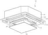
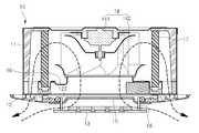
도 1 및 도 2를 참조하면, 본 실시예에 따른 공기 조화기의 실내기(10)에는, 외관을 이루며 하측이 개구되는 캐비닛(11)과, 상기 캐비닛(11)의 하측에 결합되는 프런트 패널(12)과, 상기 프런트 패널(12)에 승강 가능하게 결합되는 흡입 패널(13)과, 상기 캐비닛(11)의 내측에 구비되는 열교환기((17)와, 상기 열교환기(17)의 내측 공간에 제공되는 팬 어셈블리(14)와, 공기의 유동을 기준으로 상기 팬 어셈블리(14)의 상류 측에 구비되어 흡입되는 공기의 흐름을 안내하는 쉬라우드(16)와, 상기 프런트 패널(12)의 상측 부분에 위치되어 흡입되는 공기를 정화하는 필터(15)가 포함된다.1 and 2, the
상세히, 상기 프런트 패널(12)의 가장자리 부위에는 4개의 토출구(121)가 형성된다. 상기 프런트 패널(12)에는 토출 베인(122)이 회전 가능하게 제공된다. 따라서, 상기 토출 베인(122)의 회전 각도에 따라 토출되는 공기의 방향이 조절된다.In detail, four
또한, 상기 프런트 패널(12)의 중앙부에는 실내 공기 흡입을 위한 흡입구(111)가 형성되고, 상기 흡입구(111)는 상기 흡입 패널(13)에 의하여 선택적으로 차폐된다. 즉, 상기 실내기가 온되면, 상기 흡입 패널(13)은 상기 흡입구(111)를 개방시키고, 상기 실내기가 오프되면, 상기 흡입 패널(13)은 상기 흡입구(111)를 닫는다. 그리고, 상기 흡입구(111) 주위에는 공기 유동을 가이드하는 오리피스(123)가 형성되고, 상기 필터(15)는 상기 오리피스(123)의 상측에 설치된다.A
그리고, 상기 흡입 패널(13)의 상측에는 랙(18)이 구비되고, 상기 프런트 패널(12)의 상측부에는 상기 랙(18)과 결합되는 피니언(미도시) 및 상기 피니언을 회전시키는 구동 모터가 제공될 수 있다. 따라서, 상기 흡입 패널(13)은 상기 구동 모터의 작동에 의하여 상하 방향으로 움직이고, 상기 흡입 패널(13)의 이동에 의하여 상기 흡입구(111)가 선택적으로 개폐된다. 이 때, 상기 흡입 패널(13)이 하방으로 움직여 상기 흡입구(111)를 개방시킨 상태에서, 상기 흡입 패널(13)이 상기 흡입구(111)를 커버하므로, 상기 흡입 패널(13)에 의해서 상기 흡입구(111)의 노출이 최소화된다.A
본 실시예에서 상기 흡입 패널(13)의 승강 수단은 상기에서 제시된 랙/피니언 구조에 제한되지 아니함을 밝혀 둔다.It is to be noted that the lifting means of the
또한, 상기 흡입구(111)를 통하여 흡입되는 공기는 상기 필터(15)를 통과하 면서 이물질이 걸러진 후에, 상기 팬 어셈블리(14) 측으로 유동된다. 상세히, 상기 팬 어셈블리(14)는 축방향 흡입/반경 방향 토출 방식의 원심팬(142)과, 상기 원심팬(142)을 구동하는 팬 모터(141)로 이루어진다. 그리고, 상기 팬 어셈블리(14)에 의하여 유동되는 공기는 상기 열교환기(17)를 통과한 다음 상기 토출구(121)를 통하여 실내로 다시 토출된다.The air sucked through the
한편, 상기 흡입 패널에는 상기 캐비닛 내부에서 발생되는 소음을 저감시키기 위한 소음 저감부(134)가 적어도 하나 이상 형성된다. 상기 소음 저감부(134)는 상기 캐비닛(11) 내부에서 발생되어 상기 흡입구(111)를 통과하는 소음을 저감시킨다. 상기 소음 저감부의 구조에 대해서는 도면을 참조하여 후술하기로 한다.Meanwhile, at least one or more
이하에서는 상기 흡입 패널에 대해서 상세하게 설명한다.Hereinafter, the suction panel will be described in detail.
도 3은 제 1 실시예에 따른 흡입 패널의 사시도이고, 도 4는 상기 흡입 패널의 수직 단면도이다.FIG. 3 is a perspective view of a suction panel according to the first embodiment, and FIG. 4 is a vertical sectional view of the suction panel.
도 3 및 도 4를 참조하면, 상기 흡입 패널(13)에는, 하부 패널(131: "제 1 패널"이라고도 할 수 있음)과, 상기 하부 패널(131)의 상측에 결합되는 상부 패널(132: "제 2 패널"이라고도 할 수 있음)이 포함된다.3 and 4, the
상기 상부 패널(132)은 흡입되는 공기의 유동을 가이드하기 위하여 경사지게 형성되는 가이드면(133)이 포함된다. 상기 가이드면(133)은 상기 상부 패널(132)의 상측에서 외측 방향으로 하향 경사지게 형성된다. 즉, 상기 프런트 패널(12)의 중앙부에 상기 흡입구(111)가 형성되므로, 실내 공기를 상기 흡입구(111) 측으로 안내하기 위하여, 상기 가이드면(133)이 경사지게 형성되는 것이다.The
한편, 상기 소음 저감부(134)에는, 상기 하부 패널(131)에 형성되는 하나 이상의 소음 저감 챔버(135)와, 상기 상부 패널(132)에 형성되어 소음의 이동 통로를 제공하는 하나 이상의 연결 유로(136)가 포함된다. 그리고, 상기 상부 패널(132)과 상기 하부 패널(131)이 결합된 상태에서 상기 소음 저감 챔버(135)와, 상기 연결 유로(136)가 연통된다.The
상기 소음 저감 챔버(135)는 상기 하부 패널(131)의 상면에서 하방으로 함몰되어 형성된다. 상기 연결 유로(136)는 상기 상부 패널(132)을 상하로 관통한다.The
상기 소음 저감 챔버(135) 및 상기 연결 유로(136)는, 각각의 수평 단면이 원형 또는 사각형 등으로 형성될 수 있다. 도 3에는 상기 소음 저감 챔버(135) 및 상기 연결 유로(136)의 수평 단면이 일 례로 사각형으로 형성되는 것이 도시된다.The
그리고, 상기 소음 저감 챔버(135) 및 상기 연결 유로(136)는 공명기(resonator) 역할을 한다.The
상세히, 상기 캐비닛(11)의 내부에서 발생된 소음(일 례로 팬의 회전 시 발생되는 소음)의 특정 정상파는 상기 연결 유로(136)를 통하여 상기 소음 저감 챔버로 이동하게 된다. 그리고, 상기 소음 저감 챔버(135)로 이동된 특정 정상파는 역상(Out of phase) 형태의 진동으로 변한 후, 상기 연결 유로(136)를 통과하게 된다. 따라서, 상기 특정 정상파에 대한 위상 변위(Phase shifting)가 발생하여, 상기 캐비닛에서 발생되는 특정 정상파가 소멸하게 되고, 이에 따라 소음이 저감될 수 있다.In detail, a specific standing wave of noise generated inside the cabinet 11 (for example, noise generated when the fan rotates) is moved to the noise reduction chamber through the
이 때, 상기 소음 저감 챔버(135)의 체적과, 상기 연결 유로의 유로 단면적 및 상기 연결 유로의 길이를 가변시킴에 따라서, 다른 대역의 주파수를 가지는 소음을 저감시킬 수 있게 된다. 즉, 소음 저감부를 복수 개 형성하고, 각 소음 저감부를 구성하는 소음 저감 챔버와 연결 유로의 크기를 서로 다르게 함으로써, 다수의 주파수 대역의 소음을 저감시킬 수 있게 된다.At this time, as the volume of the
이와 같은 본 실시예에 의하면, 따라서, 상기 흡입 패널(13)에 소음 저감부를 형성함으로써, 공명기가 형성된 효과를 얻을 수 있어, 상기 실내기(10)의 작동시 발생되는 소음을 저감시킬 수 있게 된다.According to the present embodiment as described above, by forming the noise reduction portion on the
도 5는 제 2 실시예에 따른 흡입 패널의 수직 단면도이다.5 is a vertical sectional view of the suction panel according to the second embodiment.
본 실시예는 다른 부분에 있어서는 제 1 실시예와 동일하고, 다만, 흡입 패널의 형상에 있어서 차이가 있다. 따라서, 이하에서는 본 실시예의 특징적인 부분에 대해서만 설명하기로 한다.The present embodiment is the same as the first embodiment in other portions, but differs in the shape of the suction panel. Therefore, only the characteristic parts of the present embodiment will be described below.
도 5를 참조하면, 본 실시예의 흡입 패널(23)에는 하부 패널(231)과 상부 패널(232)이 포함된다. 그리고, 상기 흡입 패널(23)는 소음 저감부(234)가 구비된다.Referring to FIG. 5, the
상기 하부 패널(231) 및 상기 상부 패널(232)에는 각각 흡입되는 공기의 유동을 가이드하기 위하여 경사지게 형성되는 가이드면(231a, 232a)이 형성된다. 상기 각 가이드면(231a, 232a)은 상기 각 패널(231, 232)의 상측에서 외측 방향으로 하향 경사지게 형성된다.The
그리고, 상기 각 패널의 가이드면(231a, 232a)은 상하 방향으로 연속적으로 형성되며, 수직 단면에서 볼 때, 동일 평면을 이룬다.The
도 6은 제 3 실시예에 따른 흡입 패널의 수직 단면도이다.6 is a vertical sectional view of the suction panel according to the third embodiment.
본 실시예는 다른 부분에 있어서는 제 1 실시예와 동일하고, 다만, 흡입 패널의 형상에 있어서 차이가 있다. 따라서, 이하에서는 본 실시예의 특징적인 부분에 대해서만 설명하기로 한다.The present embodiment is the same as the first embodiment in other portions, but differs in the shape of the suction panel. Therefore, only the characteristic parts of the present embodiment will be described below.
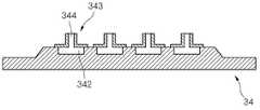
도 6을 참조하면, 본 실시예에 따른 흡입 패널(34)의 상면에는 소음 저감 챔버(342)가 함몰 형성된다. 그리고, 상기 흡입 패널(34)의 상면에는 연결 유로(344)를 정의하는 유로 형성부(344)가 결합된다. 즉, 본 실시예에서는 흡입 패널(34)이 단일의 패널로 구성되고, 연결 유로(355)를 형성하는 별도의 유로 형성부(344)가 상기 흡입 패널에 결합된다. 이는 상기 제 1 실시예에서 상부 패널에 다수의 연결 유로가 형성되는 것과 차이가 있다. 그리고, 본 실시예에서 상기 유로 형성부(344)는 상기 소음 저감 챔버(342)와 동일한 수로 구비된다.Referring to FIG. 6, a
도 7은 제 4 실시예에 따른 흡입 패널의 수직 단면도이다.7 is a vertical sectional view of the suction panel according to the fourth embodiment.
본 실시예는 다른 부분에 있어서는 제 1 실시예와 동일하고, 다만, 흡입 패널의 형상에 있어서 차이가 있다. 따라서, 이하에서는 본 실시예의 특징적인 부분에 대해서만 설명하기로 한다.The present embodiment is the same as the first embodiment in other portions, but differs in the shape of the suction panel. Therefore, only the characteristic parts of the present embodiment will be described below.
도 7을 참조하면, 본 실시예에 따른 흡입 패널(44)의 상측에는 소음 저감부를 정의하는 소음 저감 유닛(45)이 설치된다. 상기 소음 저감 유닛(45)에는 연결 유로(47)와 소음 저감 챔버(46)가 포함된다. 그리고, 상기 소음 저감 유닛(45)이 상기 흡입 패널(44)의 상측에 설치되면, 상기 소음 저감 챔버(46)는 상기 흡입 패널(45)에 의해서 커버된다.Referring to FIG. 7, a
상기의 실시예에서 설명된 소음 저감부는 일 례로 천정형 공기 조화기의 실 내기에 적용되는 것으로 설명되었으나, 이와 달리 흡입구를 선택적으로 차폐하는 흡입 패널이 구비되는 어떠한 실내라도 상기 흡입 패널에 소음 저감부가 형성 또는 결합될 수 있음을 밝혀둔다.The noise reduction unit described in the above embodiments is applied to the indoor unit of the ceiling type air conditioner. However, in any room where a suction panel for selectively shielding the suction port is provided, the noise reduction unit is formed on the suction panel Or may be combined.
도 1은 제 1 실시예에 따른 공기 조화기 실내기의 외관 사시도.1 is an external perspective view of an indoor unit of an air conditioner according to a first embodiment;
도 2는 상기 실내기의 내부 구성을 개략적으로 보여주는 수직 단면도.2 is a vertical sectional view schematically showing an internal configuration of the indoor unit.
도 3은 제 1 실시예에 따른 흡입 패널의 사시도.3 is a perspective view of a suction panel according to the first embodiment;
도 4는 상기 흡입 패널의 수직 단면도.4 is a vertical sectional view of the suction panel.
도 5는 제 2 실시예에 따른 흡입 패널의 수직 단면도.5 is a vertical sectional view of a suction panel according to a second embodiment;
도 6은 제 3 실시예에 따른 흡입 패널의 수직 단면도.6 is a vertical sectional view of the suction panel according to the third embodiment.
도 7은 제 4 실시예에 따른 흡입 패널의 수직 단면도.7 is a vertical sectional view of a suction panel according to a fourth embodiment;
Claims (10)
Translated fromKoreanPriority Applications (5)
| Application Number | Priority Date | Filing Date | Title |
|---|---|---|---|
| KR1020090001996AKR101558576B1 (en) | 2009-01-09 | 2009-01-09 | The indoor unit of the air conditioner |
| PCT/KR2009/007456WO2010079899A2 (en) | 2009-01-09 | 2009-12-11 | Air conditioner |
| US12/641,646US8146707B2 (en) | 2009-01-09 | 2009-12-18 | Air conditioner |
| EP10000112.2AEP2226576B1 (en) | 2009-01-09 | 2010-01-08 | Indoor unit of an air conditioner |
| ES10000112.2TES2602132T3 (en) | 2009-01-09 | 2010-01-08 | Indoor unit of an air conditioner |
Applications Claiming Priority (1)
| Application Number | Priority Date | Filing Date | Title |
|---|---|---|---|
| KR1020090001996AKR101558576B1 (en) | 2009-01-09 | 2009-01-09 | The indoor unit of the air conditioner |
Publications (2)
| Publication Number | Publication Date |
|---|---|
| KR20100082620A KR20100082620A (en) | 2010-07-19 |
| KR101558576B1true KR101558576B1 (en) | 2015-10-19 |
Family
ID=42316942
Family Applications (1)
| Application Number | Title | Priority Date | Filing Date |
|---|---|---|---|
| KR1020090001996AExpired - Fee RelatedKR101558576B1 (en) | 2009-01-09 | 2009-01-09 | The indoor unit of the air conditioner |
Country Status (5)
| Country | Link |
|---|---|
| US (1) | US8146707B2 (en) |
| EP (1) | EP2226576B1 (en) |
| KR (1) | KR101558576B1 (en) |
| ES (1) | ES2602132T3 (en) |
| WO (1) | WO2010079899A2 (en) |
Families Citing this family (19)
| Publication number | Priority date | Publication date | Assignee | Title |
|---|---|---|---|---|
| US10490178B2 (en)* | 2003-12-22 | 2019-11-26 | Bonnie S. Schnitta | Perforation acoustic muffler assembly and method of reducing noise transmission through objects |
| KR101632884B1 (en)* | 2008-12-23 | 2016-06-23 | 엘지전자 주식회사 | Ceiling Type Air Conditioner |
| FR2947040B1 (en)* | 2009-06-23 | 2014-01-03 | Cinier Radiateurs | REVERSIBLE RADIATOR |
| FI122961B (en)* | 2009-07-03 | 2012-09-14 | Halton Oy | Tilluftanordning |
| US8479874B2 (en)* | 2010-05-03 | 2013-07-09 | Ángel Julio Moretón Cesteros | Acoustic enclosure for loudspeakers |
| WO2013105635A1 (en)* | 2012-01-13 | 2013-07-18 | 株式会社ニコン | Chamber apparatus and heat insulating panel |
| KR102076668B1 (en)* | 2013-05-24 | 2020-02-12 | 엘지전자 주식회사 | An indoor unit for an air conditioner |
| US20150025738A1 (en)* | 2013-07-22 | 2015-01-22 | GM Global Technology Operations LLC | Methods and apparatus for automatic climate control in a vehicle based on clothing insulative factor |
| US9253556B1 (en)* | 2013-08-29 | 2016-02-02 | ConcealFab Corporation | Dissipative system for increasing audio entropy thereby diminishing auditory perception |
| CN104061658B (en)* | 2014-07-09 | 2016-10-05 | 珠海格力电器股份有限公司 | Control method for panel of air conditioner |
| JP6428895B2 (en)* | 2017-11-07 | 2018-11-28 | 新日鐵住金株式会社 | Indoor unit top plate |
| CN107882777A (en)* | 2017-11-22 | 2018-04-06 | 奥普家居股份有限公司 | A kind of suppression noise structure for blower fan |
| JP7097973B2 (en)* | 2018-07-26 | 2022-07-08 | 三菱電機株式会社 | Indoor unit and refrigeration cycle equipment |
| JP6977175B2 (en)* | 2018-08-17 | 2021-12-08 | 富士フイルム株式会社 | Soundproof structure and soundproof unit |
| CA3059947C (en)* | 2018-12-19 | 2023-05-23 | Emanuel Mouratidis | Trailing member to reduce pressure drop across a duct mounted sound attenuating baffle |
| KR102598644B1 (en)* | 2019-01-18 | 2023-11-06 | 엘지전자 주식회사 | Ceiling type air conditioner |
| US20230358437A1 (en)* | 2019-08-28 | 2023-11-09 | Broan-Nutone Llc | Sound reduction ventilation assembly |
| US11353239B2 (en) | 2019-08-28 | 2022-06-07 | Broan-Nutone Llc | Sound reduction grille assembly |
| US12283262B2 (en)* | 2021-06-24 | 2025-04-22 | Tyco Fire & Security Gmbh | Tunable silencer for air handling unit |
Citations (2)
| Publication number | Priority date | Publication date | Assignee | Title |
|---|---|---|---|---|
| JP2008241143A (en)* | 2007-03-27 | 2008-10-09 | Daikin Ind Ltd | Air conditioner |
| JP2008261519A (en) | 2007-04-10 | 2008-10-30 | Mitsubishi Electric Corp | Embedded ceiling air conditioner |
Family Cites Families (21)
| Publication number | Priority date | Publication date | Assignee | Title |
|---|---|---|---|---|
| US3537544A (en)* | 1968-06-11 | 1970-11-03 | Emerson Electric Co | Sound absorbing grille |
| JPS56165850U (en) | 1980-05-12 | 1981-12-08 | ||
| JPS56165850A (en)* | 1980-05-26 | 1981-12-19 | Toshiba Corp | Sound-proofing device for ventilation fan |
| JPH04126928A (en)* | 1990-06-20 | 1992-04-27 | Mitsubishi Electric Corp | air conditioner |
| JPH05187706A (en)* | 1992-01-08 | 1993-07-27 | Toshiba Corp | Air conditioner indoor unit |
| JP3140898B2 (en)* | 1993-12-02 | 2001-03-05 | 三菱電機株式会社 | Blower, suction panel of the device, and rectifying guide of the device |
| JP3866779B2 (en)* | 1995-02-20 | 2007-01-10 | 株式会社日立産機システム | Blower soundproofing device |
| US6116375A (en)* | 1995-11-16 | 2000-09-12 | Lorch; Frederick A. | Acoustic resonator |
| JPH1039875A (en)* | 1996-07-19 | 1998-02-13 | Mitsubishi Heavy Ind Ltd | Sound insulating material structure and soundproof structure of air conditioner |
| US6023938A (en)* | 1998-09-15 | 2000-02-15 | Carrier Corporation | Refrigeration or air conditioning unit with noise reducing grille |
| JP2001191779A (en)* | 1999-09-03 | 2001-07-17 | Denso Corp | Air conditioner for vehicle |
| JP4378816B2 (en)* | 1999-12-20 | 2009-12-09 | 株式会社富士通ゼネラル | Embedded ceiling air conditioner |
| US6668970B1 (en)* | 2001-06-06 | 2003-12-30 | Acoustic Horizons, Inc. | Acoustic attenuator |
| US6606876B1 (en)* | 2002-05-28 | 2003-08-19 | Carrier Corporation | Silencer for rear mounted bus air conditioner |
| US20050161280A1 (en)* | 2002-12-26 | 2005-07-28 | Fujitsu Limited | Silencer and electronic equipment |
| JP4145278B2 (en)* | 2004-09-03 | 2008-09-03 | 明星工業株式会社 | Sound absorber |
| US7314113B2 (en)* | 2004-09-14 | 2008-01-01 | Cray Inc. | Acoustic absorbers for use with computer cabinet fans and other cooling systems |
| KR101174509B1 (en)* | 2005-02-28 | 2012-08-16 | 엘지전자 주식회사 | Ceiling embedded air conditioner and air inlet sstructure of the same |
| US8092285B2 (en)* | 2006-03-21 | 2012-01-10 | Calsonickansei North America, Inc. | System and method for controlling a ventilation unit of a vehicle |
| JP3998032B1 (en)* | 2006-04-18 | 2007-10-24 | ダイキン工業株式会社 | Air conditioner indoor unit |
| BRPI0700554A (en)* | 2007-01-30 | 2008-09-16 | Whirlpool Sa | resonator arrangement for refrigeration cabinet |
- 2009
- 2009-01-09KRKR1020090001996Apatent/KR101558576B1/ennot_activeExpired - Fee Related
- 2009-12-11WOPCT/KR2009/007456patent/WO2010079899A2/enactiveApplication Filing
- 2009-12-18USUS12/641,646patent/US8146707B2/ennot_activeExpired - Fee Related
- 2010
- 2010-01-08ESES10000112.2Tpatent/ES2602132T3/enactiveActive
- 2010-01-08EPEP10000112.2Apatent/EP2226576B1/ennot_activeNot-in-force
Patent Citations (2)
| Publication number | Priority date | Publication date | Assignee | Title |
|---|---|---|---|---|
| JP2008241143A (en)* | 2007-03-27 | 2008-10-09 | Daikin Ind Ltd | Air conditioner |
| JP2008261519A (en) | 2007-04-10 | 2008-10-30 | Mitsubishi Electric Corp | Embedded ceiling air conditioner |
Also Published As
| Publication number | Publication date |
|---|---|
| US20100175411A1 (en) | 2010-07-15 |
| EP2226576B1 (en) | 2016-08-10 |
| EP2226576A3 (en) | 2012-11-07 |
| WO2010079899A3 (en) | 2010-09-23 |
| US8146707B2 (en) | 2012-04-03 |
| KR20100082620A (en) | 2010-07-19 |
| EP2226576A2 (en) | 2010-09-08 |
| ES2602132T3 (en) | 2017-02-17 |
| WO2010079899A2 (en) | 2010-07-15 |
Similar Documents
| Publication | Publication Date | Title |
|---|---|---|
| KR101558576B1 (en) | The indoor unit of the air conditioner | |
| KR101624743B1 (en) | Indoor unit of air conditioner | |
| KR102313905B1 (en) | air guide for ceiling type air conditioner and ceiling type air conditioner having the same | |
| JP2015067260A (en) | Vehicular air conditioner | |
| KR101392315B1 (en) | Indoor unit of an air conditioner | |
| AU2020460634B2 (en) | Air guide box and internal-circulation range hood thereof | |
| KR101558577B1 (en) | Indoor unit of air conditioner | |
| KR20080019357A (en) | Air conditioner | |
| JP4650470B2 (en) | Engine-driven air conditioning system housing | |
| KR20070078261A (en) | Indoor unit of air conditioner | |
| KR100644544B1 (en) | Air conditioner | |
| CN106091066A (en) | Fume exhaust fan | |
| US20250294649A1 (en) | Cooking appliance | |
| KR20070078258A (en) | Indoor unit of air conditioner | |
| KR101558578B1 (en) | Indoor unit of air conditioner | |
| KR100584298B1 (en) | Integrated Air Conditioner | |
| CN218787597U (en) | New fan of side direction air inlet | |
| JP4300666B2 (en) | Floor-mounted air conditioner | |
| KR100697198B1 (en) | Indoor unit of air conditioner | |
| KR100626448B1 (en) | Integrated Air Conditioner | |
| CN120120617A (en) | Air-conditioning type range hood | |
| KR100727878B1 (en) | Air conditioner | |
| KR20070000897A (en) | Turbofan | |
| KR20050049256A (en) | Air flow structure of outdoor portion for thru the wall type air conditioner | |
| KR20050098989A (en) | Microwave oven |
Legal Events
| Date | Code | Title | Description |
|---|---|---|---|
| PA0109 | Patent application | St.27 status event code:A-0-1-A10-A12-nap-PA0109 | |
| R18-X000 | Changes to party contact information recorded | St.27 status event code:A-3-3-R10-R18-oth-X000 | |
| R18-X000 | Changes to party contact information recorded | St.27 status event code:A-3-3-R10-R18-oth-X000 | |
| PG1501 | Laying open of application | St.27 status event code:A-1-1-Q10-Q12-nap-PG1501 | |
| R17-X000 | Change to representative recorded | St.27 status event code:A-3-3-R10-R17-oth-X000 | |
| A201 | Request for examination | ||
| PA0201 | Request for examination | St.27 status event code:A-1-2-D10-D11-exm-PA0201 | |
| E902 | Notification of reason for refusal | ||
| PE0902 | Notice of grounds for rejection | St.27 status event code:A-1-2-D10-D21-exm-PE0902 | |
| E13-X000 | Pre-grant limitation requested | St.27 status event code:A-2-3-E10-E13-lim-X000 | |
| P11-X000 | Amendment of application requested | St.27 status event code:A-2-2-P10-P11-nap-X000 | |
| P13-X000 | Application amended | St.27 status event code:A-2-2-P10-P13-nap-X000 | |
| PN2301 | Change of applicant | St.27 status event code:A-3-3-R10-R13-asn-PN2301 St.27 status event code:A-3-3-R10-R11-asn-PN2301 | |
| R17-X000 | Change to representative recorded | St.27 status event code:A-3-3-R10-R17-oth-X000 | |
| E701 | Decision to grant or registration of patent right | ||
| PE0701 | Decision of registration | St.27 status event code:A-1-2-D10-D22-exm-PE0701 | |
| GRNT | Written decision to grant | ||
| PR0701 | Registration of establishment | St.27 status event code:A-2-4-F10-F11-exm-PR0701 | |
| PR1002 | Payment of registration fee | St.27 status event code:A-2-2-U10-U11-oth-PR1002 Fee payment year number:1 | |
| PG1601 | Publication of registration | St.27 status event code:A-4-4-Q10-Q13-nap-PG1601 | |
| PR1001 | Payment of annual fee | St.27 status event code:A-4-4-U10-U11-oth-PR1001 Fee payment year number:4 | |
| PR1001 | Payment of annual fee | St.27 status event code:A-4-4-U10-U11-oth-PR1001 Fee payment year number:5 | |
| PN2301 | Change of applicant | St.27 status event code:A-5-5-R10-R13-asn-PN2301 St.27 status event code:A-5-5-R10-R11-asn-PN2301 | |
| PR1001 | Payment of annual fee | St.27 status event code:A-4-4-U10-U11-oth-PR1001 Fee payment year number:6 | |
| P22-X000 | Classification modified | St.27 status event code:A-4-4-P10-P22-nap-X000 | |
| PR1001 | Payment of annual fee | St.27 status event code:A-4-4-U10-U11-oth-PR1001 Fee payment year number:7 | |
| PR1001 | Payment of annual fee | St.27 status event code:A-4-4-U10-U11-oth-PR1001 Fee payment year number:8 | |
| PC1903 | Unpaid annual fee | St.27 status event code:A-4-4-U10-U13-oth-PC1903 Not in force date:20231002 Payment event data comment text:Termination Category : DEFAULT_OF_REGISTRATION_FEE | |
| PC1903 | Unpaid annual fee | St.27 status event code:N-4-6-H10-H13-oth-PC1903 Ip right cessation event data comment text:Termination Category : DEFAULT_OF_REGISTRATION_FEE Not in force date:20231002 |