KR101555342B1 - Micro-grid system and controling method for thereof - Google Patents
Micro-grid system and controling method for thereofDownload PDFInfo
- Publication number
- KR101555342B1 KR101555342B1KR1020140143482AKR20140143482AKR101555342B1KR 101555342 B1KR101555342 B1KR 101555342B1KR 1020140143482 AKR1020140143482 AKR 1020140143482AKR 20140143482 AKR20140143482 AKR 20140143482AKR 101555342 B1KR101555342 B1KR 101555342B1
- Authority
- KR
- South Korea
- Prior art keywords
- power
- grid
- storage device
- voltage
- frequency
- Prior art date
- Legal status (The legal status is an assumption and is not a legal conclusion. Google has not performed a legal analysis and makes no representation as to the accuracy of the status listed.)
- Active
Links
Images


Classifications
- H—ELECTRICITY
- H02—GENERATION; CONVERSION OR DISTRIBUTION OF ELECTRIC POWER
- H02J—CIRCUIT ARRANGEMENTS OR SYSTEMS FOR SUPPLYING OR DISTRIBUTING ELECTRIC POWER; SYSTEMS FOR STORING ELECTRIC ENERGY
- H02J3/00—Circuit arrangements for AC mains or AC distribution networks
- H02J3/38—Arrangements for parallely feeding a single network by two or more generators, converters or transformers
- H02J3/381—Dispersed generators
- G—PHYSICS
- G05—CONTROLLING; REGULATING
- G05B—CONTROL OR REGULATING SYSTEMS IN GENERAL; FUNCTIONAL ELEMENTS OF SUCH SYSTEMS; MONITORING OR TESTING ARRANGEMENTS FOR SUCH SYSTEMS OR ELEMENTS
- G05B13/00—Adaptive control systems, i.e. systems automatically adjusting themselves to have a performance which is optimum according to some preassigned criterion
- G05B13/02—Adaptive control systems, i.e. systems automatically adjusting themselves to have a performance which is optimum according to some preassigned criterion electric
- H—ELECTRICITY
- H02—GENERATION; CONVERSION OR DISTRIBUTION OF ELECTRIC POWER
- H02J—CIRCUIT ARRANGEMENTS OR SYSTEMS FOR SUPPLYING OR DISTRIBUTING ELECTRIC POWER; SYSTEMS FOR STORING ELECTRIC ENERGY
- H02J2300/00—Systems for supplying or distributing electric power characterised by decentralized, dispersed, or local generation
- H02J2300/20—The dispersed energy generation being of renewable origin
Landscapes
- Engineering & Computer Science (AREA)
- Software Systems (AREA)
- Artificial Intelligence (AREA)
- Computer Vision & Pattern Recognition (AREA)
- Evolutionary Computation (AREA)
- Medical Informatics (AREA)
- Health & Medical Sciences (AREA)
- Physics & Mathematics (AREA)
- General Physics & Mathematics (AREA)
- Automation & Control Theory (AREA)
- Power Engineering (AREA)
- Charge And Discharge Circuits For Batteries Or The Like (AREA)
- Supply And Distribution Of Alternating Current (AREA)
Abstract
Translated fromKoreanDescription
Translated fromKorean본 발명은 마이크로 그리드 시스템 및 그 제어방법에 관한 것이다.The present invention relates to a microgrid system and a control method thereof.
최근, 태양광 발전설비나 풍력 발전설비 드의 이른바 신재생 에너지를 이용한 발전설비(이하 「신재생에너지 발전설비」라고 한다)를 포함하는 마이크로 그리드의 개발 및 이용이 증가하고 있다.In recent years, the development and use of micro-grids including solar power generation facilities and wind power generation facilities including so-called renewable energy generation facilities (hereinafter referred to as "renewable energy generation facilities") are increasing.
태양광이나 풍력 등을 이용한 신재생에너지 발전설비는 일사량이나 풍속 등의 자연조건에 따라서 시시각각 출력이 변동하므로 예를 들어 농어촌이나 낙도 등과 같은 취약한 전력계통에서는 계통의 주파수나 전압의 변동의 발생이 운용상의 중요한 기술적 과제가 되며, 이와 같은 문제의 해결을 위해 배터리 등의 에너지저장장치를 이용하여, 이 에너지 저장장치에의 충전 및 방전을 통해서 전력계통의 안정화를 도모하고 있으며, 이와 같은 마이크로 그리드의 전압 변동을 제어하는 종래기술로 특허문헌 1에 기재된 기술이 있다.Renewable energy generation facilities using sunlight or wind power fluctuate output momentarily depending on natural conditions such as solar radiation and wind speed. For example, in a weak power system such as rural areas or remote islands, In order to solve such a problem, an energy storage device such as a battery is used to stabilize the power system by charging and discharging the energy storage device. In order to solve such a problem, There is a technique described in
도 1은 종래의 마이크로 그리드의 전압제어장치의 대략적인 구성을 나타내는 도면이다.1 is a diagram showing a schematic configuration of a conventional voltage control apparatus for a micro grid.
특허문헌 1의 마이크로 그리드는 부하 또는 계통에 공급할 전력을 생성하는 풍력발전기(10) 및 디젤발전기(12)와, 풍력발전기(10) 또는 디젤발전기(12)가 생성하는 전력을 저장하는 에너지 저장부(14)와, 풍력 발전기(10)의 출력 상태에 따라 디젤발전기(12)의 무효전력을 제어하여 디젤발전기(12)에서 생성된 무효전력을 에너지 저장부(14)에 저장시키고, 부하 또는 계통의 연계점(18)에서 측정된 전압이 허용 범위보다 낮아지는 경우에 에너지 저장부(14)에 저장된 무효전력이 부하 또는 계통에 공급되도록 하는 제어부(16)로 구성되며, 이와 같이 디젤발전기(12)의 무효전력을 이용하여 계통 연계점의 전압 제어를 수행함으로써 안정한 계통운영이 가능하게 하고 있다.The microgrid of
또, 마이크로 그리드의 주파수 안정성의 향상을 목적으로 하는 종래기술로 특허문헌 2에 기재된 기술이 있다.Also, there is a technique described in Patent Document 2 as a conventional technique for improving the frequency stability of the microgrid.
도 2는 종래의 마이크로 그리드의 수요제어장치의 대략적인 구성을 나타내는 도면이다.2 is a diagram showing a schematic configuration of a conventional demand control apparatus for a micro grid.
특허문헌 2의 마이크로 그리드는 송전망(21)에 신재생에너지 이용 발전설비(25)와 이를 보충하는 내연력 발전설비(23) 및 에너지 저장장치(24)를 접속하여 부하(26)에 전력을 공급하는 마이크로 그리드(20)에서, 예측기능부(27), 수요계획부(28) 및 경제부하배분 제어부(29)에 의한 내연력 발전기 출력(30) 및 축전지 출력(232)의 제어를 하고, 부하 주파수 제어부(31)에 의한 계통 주파수 및 연계선 조류를 이용한 제어에 의해 안정적인 계통 주파수를 유지하면서 전력수급제어를 하고 있다.The micro grid of Patent Document 2 connects a renewable energy utilization
특허문헌 1의 기술은 마이크로 그리드의 계통전압의 변동에 대해서는 대응이 가능하나, 주파수 변동에 대해서는 해결방안을 제시하고 있지 않으며, 이와는 역으로, 특허문헌 2의 기술은 마이크로 그리드의 주파수 변동에 대해서는 대응이 가능하나, 계통전압의 변동에 대한 해결방안은 직접적으로 제시하고 있지 않다.The technology of
본 발명은 이와 같은 종래기술의 문제를 고려하여 이루어진 것으로, 계통전압의 변동 및 주파수 변동을 함께 고려하면서 마이크로 그리드를 효율적으로 운영할 수 있는 마이크로 그리드 시스템 및 그 제어방법을 제공하는 것을 목적으로 한다.SUMMARY OF THE INVENTION It is an object of the present invention to provide a micro grid system and a control method thereof that can efficiently operate a micro grid while simultaneously considering variations in system voltage and frequency variation.
상기 과제를 해결하기 위한 본 발명의 마이크로 그리드 시스템 제어방법은, 재생 가능한 에너지를 에너지원으로 하여 전력을 생산하는 분산전원과 화석연료를 에너지원으로 하여 전력을 생산하는 발전설비 및 상기 발전설비에서 생산된 전력을 충전 및 방전하는 전력저장장치를 포함하는 마이크로 그리드 시스템의 제어방법으로, 상기 전력저장장치의 충전상태 및 상기 발전설비의 동작상태를 확인하고, 상기 전력저장장치의 충전상태를 기초로 상기 전력저장장치와 상기 발전설비 중 어느 하나를 마스터로 설정하고, 나머지 하나를 슬레이브로 설정하는 마스터 슬레이브 설정단계와, 상기 마이크로 그리드 시스템과 부하 사이를 접속하는 계통 연계점에서의 전압 및 주파수를 측정하여 계통전압 및 계통주파수를 취득하는 계통전압 및 계통주파수 취득단계와, 상기 계통전압 및 계통주파수 취득단계에서 취득한 계통전압 및 계통주파수와 마스터 슬레이브 설정단계에서 설정된 마스터와 슬레이브를 기초로 상기 전력저장장치와 상기 발전설비 사이의 전력공급량을 결정하는 전력공급량 결정단계를 포함한다.According to an aspect of the present invention, there is provided a micro grid system control method including: a distributed power source for generating electric power using renewable energy as an energy source; a power generation facility for generating electric power using fossil fuel as an energy source; And a power storage device for charging and discharging the power stored in the power storage device, the method comprising: confirming a charged state of the power storage device and an operation state of the power generation facility, A master slave setting step of setting either one of the power storage device and the power generation equipment as a master and the other as a slave; and measuring a voltage and frequency at a grid connection point connecting the microgrid system and the load Grid voltage and grid frequency acquisition to obtain grid voltage and grid frequency Determining a power supply amount to determine a power supply amount between the power storage device and the power generation facility based on the grid voltage and the grid frequency acquired in the grid voltage and grid frequency acquisition step and the master and slave set in the master slave setting step; .
상기 과제를 해결하기 위한 본 발명의 마이크로 그리드 시스템은, 재생 가능한 에너지를 에너지원으로 하여 전력을 생산하는 분산전원과, 화석연료를 에너지원으로 하여 전력을 생산하는 발전설비와, 상기 발전설비에서 생산된 전력을 충전 및 방전하는 전력저장장치와, 상기 분산전원과 상기 발전설비 및 상기 전력저장장치를 제어하는 제어수단을 포함하고, 상기 제어수단은, 상기 전력저장장치의 충전상태 및 상기 발전설비의 동작상태를 확인하고, 상기 전력저장장치의 충전상태를 기초로 상기 전력저장장치와 상기 발전설비 중 어느 하나를 마스터로 설정하며, 나머지 하나를 슬레이브로 설정하고, 마이크로 그리드 시스템과 부하 사이를 접속하는 계통 연계점에서의 전압 및 주파수를 측정하여 계통전압 및 계통주파수를 취득하는 계통전압 및 계통주파수 취득하며, 상기 계통전압 및 상기 계통주파수와 설정된 상기 마스터 및 상기 슬레이브를 기초로 상기 전력저장장치와 상기 발전설비 사이의 전력공급량을 결정한다.According to an aspect of the present invention, there is provided a micro grid system including a distributed power source for generating electric power using renewable energy as an energy source, a power generation facility for generating electric power using fossil fuel as an energy source, And a control means for controlling the distributed power source, the power generation facility, and the power storage device, wherein the control means controls the charging state of the power storage device and the power storage device The power storage device and the power generation facility are set as the master and the other is set as the slave based on the charging state of the power storage device and the connection between the micro grid system and the load Grid voltage to obtain the grid voltage and the grid frequency by measuring the voltage and frequency at the grid connection point and Tube acquires frequency, determines a power supply between the power plant and the power storage device based on the grid voltage and the grid frequency, and set the master and the slave.
상기 본 발명에 의하면 계통전압의 변동 및 주파수 변동을 함께 고려하면서 마이크로 그리드 시스템을 효율적으로 운영 및 제어할 수 있는 마이크로 그리드 시스템 및 그 제어방법을 제공할 수 있다.According to the present invention, it is possible to provide a micro grid system and a control method thereof that can efficiently operate and control the micro grid system while simultaneously considering variations in system voltage and frequency variation.
도 1은 종래의 마이크로 그리드의 전압제어장치의 대략적인 구성을 나타내는 도면,
도 2는 종래의 마이크로 그리드의 주파수제어장치의 대략적인 구성을 나타내는 도면,
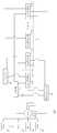
도 3은 본 발명의 바람직한 실시형태의 마이크로 그리드 운영제어시스템의 개략적인 구성을 나타내는 도면,
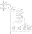
도 4는 본 발명의 바람직한 실시형태의 마이크로 그리드 운영제어시스템의 전체적인 제어의 흐름을 나타내는 플로차트,
도 5는 도 4의 시스템 체크 상태의 제어의 흐름을 나타내는 플로차트,
도 6은 도 4의 정상운전상태에서의 제어의 흐름을 나타내는 플로차트,
도 7은 도 4의 비상운전상태에서의 제어의 흐름을 나타내는 플로차트(도 8에 계속),
도 8은 도 4의 비상운전상태에서의 제어의 흐름을 나타내는 플로차트(도 7에서 계속),
도 9는 도 4의 배터리 및 덤프 로드 체크의 흐름을 나타내는 플로차트이다.BRIEF DESCRIPTION OF THE DRAWINGS FIG. 1 is a diagram showing a schematic configuration of a conventional voltage control device for a micro grid;
2 is a diagram showing a schematic configuration of a conventional microgrid frequency control device,
3 is a diagram showing a schematic configuration of a micro grid operation control system of a preferred embodiment of the present invention,
4 is a flow chart showing the overall control flow of the micro grid operation control system of the preferred embodiment of the present invention;
5 is a flowchart showing the flow of control in the system check state of Fig. 4,
Fig. 6 is a flow chart showing the flow of control in the normal operation state of Fig. 4,
Fig. 7 is a flowchart (flow chart of Fig. 8) showing the flow of control in the emergency operation state of Fig. 4,
8 is a flow chart (continued in Fig. 7) showing the flow of control in the emergency operation state of Fig. 4,
Fig. 9 is a flowchart showing the flow of the battery and dump load check of Fig. 4; Fig.
이하, 본 발명의 바람직한 실시형태에 대해 첨부 도면을 참조하면서 상세하게 설명한다. 도 3은 본 발명의 바람직한 실시형태의 마이크로 그리드 운영제어시스템의 개략적인 구성을 나타내는 도면이다.Hereinafter, preferred embodiments of the present invention will be described in detail with reference to the accompanying drawings. 3 is a diagram showing a schematic configuration of a micro grid operating control system according to a preferred embodiment of the present invention.
도 3에 도시하는 것과 같이 본 발명의 바람직한 실시형태의 마이크로 그리드 시스템(100)은 디젤발전기(110)와, 전력저장장치(120)와, 예를 들어 풍력발전기(131)와 태양광발전기(132) 및 지열발전기(133) 등과 같은 재생 가능한 에너지를 발전 원으로 이용하는 분산전원(130)과, 제어부(140) 및 덤프 로드(150)를 포함하며, 이와 같은 마이크로 그리드 시스템(100)은 계통 연계점(160)을 통해서 복수의 부하(170)와 접속되어 있다.3, the
디젤발전기(110)는 중유와 같은 화석연료를 에너지원으로 하는 발전설비이며, 전력저장장치(120) 및 분산전원(130)과 함께 복수의 부하(170)에 대한 전력 공급을 담당한다. 따라서 본 실시형태에서는 이와 같은 화석연료를 에너지원으로 하는 내연력 발전설비의 예로 디젤발전기를 예로 들어서 설명하나, 반드시 중유를 사용하는 디젤발전기에 한정되는 것은 아니며, 예를 들어 석탄을 연료로 사용하는 발전설비 등도 포함하여 화석연료를 에너지원으로 하는 내연력 발전설비 모두를 포함한다.The
전력저장장치(120)는 예를 들어 충전 및 방전 가능한 2차 전지나 커패시터 등으로 구성되며, 디젤발전기(110) 및 분산전원(130)과 함께 복수의 부하(170)에 대한 전력 공급을 담당한다. 설명의 편의상 이하의 설명에서는 전력저장장치(120)가 배터리인 것으로 하여 설명한다.The
분산전원(130)은 예를 들어 풍력발전기(131), 태양광발전기(132), 지열발전기(133) 등과 같이 재생 가능한 에너지를 이용한 발전설비이다. 분산전원(130)은 날씨나 계절 등의 영향에 따라서 출력이 변동된다는 특성이 있으므로 전력저장장치(120)에 대한 충전 및 방전을 통해서 출력을 가능한 한 평준화시키는 동시에, 필요에 따라서는 디젤발전기(110)의 가동에 의한 부족분의 보충을 통해서 부하(170)가 요구하는 전력의 수요와 재생 가능 에너지를 이용하는 분산전원(130)의 출력 간의 균형의 유지가 필요하다.The
도 3에서는 분산전원(130)으로 풍력발전기(131), 태양광발전기(132) 및 지열발전기(133)를 모두 구비하는 것으로 하고 있으나, 분산전원(130)으로는 풍력발전기(131) 만을 구비해도 좋고, 태양광발전기(132) 만을 구비해도 좋으며, 지열발전기(133) 만을 구비해도 좋다. 또, 이들 각 발전기는 한대만 구비하는 것으로 해도 좋고 2대 이상을 구비하는 것으로 해도 좋으며, 이는 마이크로 그리드 시스템이 설치되는 현장의 재생 가능 에너지원의 획득 가능성, 각각의 발전기의 용량 및 이들이 담당할 부하의 크기 등에 따라서 결정될 수 있다. 또, 이는 디젤발전기(110)에 대해서도 동일하다.Although the
덤프 로드(150)는 분산전원(130)에서 생산된 전력 중 상기 전력저장장치(120)에 저장하고 남는 전력을 소비하는 장치이며, 예를 들어 전기에너지를 열에너지로 변환하여 소비하는 저항체 등으로 구성된다.The
제어부(140)는 마이크로 그리드 시스템(100)을 구성하는 각 부를 제어하며, 이를 위해 디젤발전기(110), 전력저장장치(120), 풍력발전기(131), 태양광발전기(132), 지열발전기(133)와 연계하여, 각각의 상태를 감시하는 동시에 이들 각각이 생산하거나 또는 저장하고 있는 전력정보를 수집한다. 또, 제어부(140)는 후술하는 계통 연계점(160)에서 부하(170)로 공급되는 전력의 전압 및 주파수를 감시한다.The
제어부(140)는 프로세서 및 메모리장치 등을 포함하는 컴퓨터 시스템이며, 메모리장치에 본 실시형태의 마이크로 그리드 시스템(100) 제어용 프로그램 및 각종 데이터를 예를 들어 룩 업 테이블 형태로 저장하고 있고, 프로세서가 메모리장치에 저장된 프로그램에 따라서 동작함으로써 본 발명이 실행되며, 동작의 상세에 대해서는 후술한다.The
계통 연계점(Point of Common Coupling : PCC, 160)은 마이크로 그리드 시스템(100)과 복수의 부하(170) 사이를 연결한다.A point of common coupling (PCC) 160 connects the
부하(170)는 예를 들어 일반 가정이나 공장 등과 같이 전력을 소비하는 전력 소비자이다.The
다음에, 이상의 구성을 갖는 본 실시형태의 마이크로 그리드 시스템(100)의 동작에 대해 설명한다. 도 4는 본 발명의 바람직한 실시형태의 마이크로 그리드 운영제어시스템의 전체적인 제어의 흐름을 나타내는 플로차트, 도 5는 도 4의 시스템 체크 상태의 제어의 흐름을 나타내는 플로차트, 도 6은 도 4의 정상운전상태에서의 제어의 흐름을 나타내는 플로차트, 도 7 및 8은 도 4의 비상운전상태에서의 제어의 흐름을 나타내는 플로차트, 도 9는 도 4의 배터리 및 덤프 로드 체크의 흐름을 나타내는 플로차트이다.Next, the operation of the
먼저, 도 4를 참조하면, 마이크로 그리드 시스템(100)에 대한 제어가 시작되면, 단계 S100에서 제어부(140)는 마이크로 그리드 시스템(100)의 각 부를 체크하여, 시스템의 전압과 주파수를 제어하는 제어의 주체를 결정한다.4, when the
구체적으로는, 도 5에 나타내는 것과 같이, 단계 S101에서 제어부(140)는 전력저장장치(120)의 배터리의 상태를 확인하고, 배터리의 상태가 정상이면 단계 S102로 진행하여 전력저장장치(120)의 배터리를 마스터로 설정하고, 단계 S103에서 디젤발전기(110)의 상태를 확인한다. 단계 S103에서 디젤발전기(110)의 상태가 정상이면 단계 S200으로 진행하고, 디젤발전기(110)의 상태가 정상이 아니면 단계 S108에서 디젤발전기 알람을 동작시켜서 디젤발전기의 상태가 비정상이라는 경고를 한 후에 단계 S200으로 진행한다.5, in step S101, the
여기서, 디젤발전기(110)의 상태 확인은 후술하는 단계 S104에서도 실행하고 있으므로 단계 S103 및 단계S108은 실행해도 좋고 생략해도 좋다.Here, the state check of the
만일, 단계 S101에서 배터리의 상태가 비정상으로 판정되면 단계 S104로 진행하여 디젤발전기(110)의 상태가 정상인가를 판정하고, 단계 S105에서 배터리의 상태가 비정상이라는 경고 알람을 동작시킨 후, 단계 S106으로 진행하여 디젤발전기(110)를 마스터로 설정하고 배터리를 슬레이브로 설정한 후, 단계 S200으로 진행한다.If it is determined in step S101 that the state of the battery is abnormal, the process proceeds to step S104 to determine whether the state of the
여기서, 디젤발전기(110)를 마스터로 설정한다는 것은 마이크로 그리드 시스템(100)과 부하(170)를 연결하는 계통 연계점(160)에서의 계통의 전압 및 주파수의 제어를 디젤발전기(110)가 주로 담당하고, 슬레이브인 전력저장장치(120)의 배터리는 계통의 전압 및 주파수의 제어를 보조하도록 동작하는 것을 의미한다.Setting the
역으로, 전력저장장치(120)의 배터리를 마스터로 설정하고 디젤발전기(110)를 슬레이브로 설정하면 계통의 전압 및 주파수의 제어를 배터리가 주로 담당하고 디젤발전기(110)는 계통의 전압 및 주파수의 제어를 보조하도록 동작하게 된다.Conversely, when the battery of the
만일 단계 S104에서 디젤발전기(110)가 정상이 아닌 것으로 판정되면, 그 앞의 단계인 단계 S101에서 전력저장장치(120)의 배터리도 비정상이었으므로 제어부(140)는 마이크로 그리드 시스템(100)의 동작이 불가능한 것으로 판정하게 되며, 단계 S107에서 시스템 정지 알람을 동작시키고 단계 S108에서 시스템을 정지시킨 후 종료한다.If it is determined in step S104 that the
이어서, 단계 S200에서는 제어부(140)는 계통 연계점(160)에서의 계통주파수(fCC) 및 계통전압(VPCC)을 측정하고, 제어부(140)가 저장하고 있는 기준주파수(fr) 및 기준전압(Vr)과 측정된 계통주파수(fCC) 및 계통전압(VPCC)과의 차를 구해서, 이들 차의 절대치 abs(fr-fCC) 및 abs(Vr-VCC)가 각각 마이크로 그리드 시스템(100)의 정상운전이 가능한가, 아니면 비상운전을 해야 하는가 여부를 결정하는 지표인 임계주파수(f1) 및 임계전압(V1) 이상인가를 판단한다.In step S200, the
단계 S200의 판정결과 계통 연계점(160)에서의 기준주파수(fr) 및 기준전압(Vr)과 측정된 계통주파수(fCC) 및 계통전압(VPCC)과의 차의 절대치 abs(fr-fCC) 및 abs(Vr-VCC)가 각각 임계주파수(f1) 및 임계전압(V1)보다 작으면, 즉 abs(fr-fCC)>f1이고 abs(Vr-VCC)>V1이면(단계 S200=YES) 도 4의 단계 S300으로 진행하여 비상운전을 하고, 단계 S200에서의 판정결과가 그 반대의 결과, 즉 abs(fr-fCC)<f1이고 abs(Vr-VCC)<V1이면(단계 S200=NO) 도 4의 단계 S300으로 진행하여 정상운전을 한다.As a result of the determination in step S200, the absolute value abs (f (r )) of the difference between the reference frequency fr and the reference voltage Vr at the
이어서, 마이크로 그리드 시스템(100)의 정상운전에 대해 도 4 및 6을 참조하면서 상세하게 설명한다.Next, the normal operation of the
단계 S200에서의 판정결과가 abs(fr-fCC)<f1이고 abs(Vr-VCC)<V1이면 제어부(140)는 단계 S301로 진행하여 배터리에 충전되어 있는 현재의 총 피상전력(SB)과 복수의 부하(170)에서 필요로 하는 피상전력인 부하요구 피상전력(SL)과 부하(170)에 안정적으로 요구전력을 공급하기 위한 전력마진(SM1(SL))의 합과의 크기를 비교하여, 배터리에 충전되어 있는 총 피상전력(SB)의 값이 부하요구 피상전력(SL)과 전력마진(SM1(SL))의 합보다 크면, 즉 SB>SL+SM1(SL)의 관계이면 전력저장장치(120)의 배터리에 충전된 전력만으로 부하(170)에 전력공급을 계속하는 동시에 단계 S500으로 진행하고, 역으로, 배터리에 충전되어 있는 총 피상전력(SB)의 값이 부하요구 피상전력(SL)과 전력마진(SM1(SL))의 합보다 작으면, 즉 SB<SL+SM1(SL)의 관계이면 단계 S302로 진행하여 디젤발전기(110)가 가동중인가를 판단한다.If the determination result in step S200 is abs (fr -fCC ) <f1 and abs (Vr -VCC ) <V1, the controller 140 proceeds to step S301 to determine whether or not the current total appearance power (SB) and the apparent power of the load required apparent power, the power margin to reliably supply the required power to the (SL) and the load (170) required by the plurality of load 170 (SM1 (SL ), And when the value of the total apparent power SB charged in the battery is larger than the sum of the load required apparent power SL and the power margin SM1 (SL ) , That is, if SB > SL + SM1 (SL ), the power supply to the
단계 S302의 판정결과 디젤발전기(110)가 가동중이면 제어부(140)는 단계 S303으로 진행하여 디젤발전기(110)의 기준 피상전력(SDr)의 크기를 부하요구 피상전력(SL)과 전력마진(SM1(SL))의 합에서 배터리에 충전되어 있는 총 피상전력(SB)을 뺀 값보다 크도록, 즉, SDr>SL+SM(SL)-SB의 관계를 가지도록 디젤발전기(110)의 운전상태를 설정하고, 단계 S304로 진행한다.If it is determined in step S302 that the
다시 말해, 단계 S303에서는 제어부(140)는 디젤발전기(110)의 운전상태를 부하(170)에서 필요로 하는 전체 피상전력의 양 중 현재 전력저장장치(120)의 배터리에 저장되어 있는 총 피상전력의 양, 즉, 배터리가 담당할 수 있는 피상전력의 양의 부족분을 충당하도록 운전상태를 설정한다.In other words, in step S303, the
이어서, 단계 S304에서 제어부(140)는 분산전원(130)의 풍력발전기(131)가 가동중인가를 판단하고, 풍력발전기(131)가 가동중이면 단계 S305로 진행하여 0 또는 부하요구 피상전력(SL)과 전력마진(SM1)의 합에서 배터리에 충전되어 있는 총 피상전력(SB)의 값 및 디젤발전기(110)의 피상전력의 마진(SDm)의 값을 뺀 값 중 큰 값을 풍력발전기(131)가 생산하는 전력의 기준이 되는 풍력발전기의 기준 피상전력(SWTr)으로 설정, 즉 0과 (SL+SM1-SB-SDm)의 값 중 큰 값을 풍력발전기의 기준 피상전력(SWTr)로 설정하고 단계 S306으로 진행한다.In step S304, the
만일 단계 S304에서 풍력발전기(131)가 가동중이 아니면 단계 S308로 진행하여 풍력발전기(131)를 가동하고 단계 S305로 진행하여 앞에서 설명한 단계 S305의 제어를 실행한다.If the
이어서, 단계 S306에서 제어부(140)는 배터리에 충전되어 있는 총 피상전력(SB)을 배터리의 기준 피상전력(SBr)으로 설정하고, 디젤발전기(110)의 피상전력의 마진(SDm)과 디젤발전기(110)의 기준 피상전력(SDr)에서 풍력발전기(131)의 기준 피상전력(SWT)을 뺀 값 중 큰 값을 디젤발전기(110)의 기준 피상전력(SDr)으로 설정, 즉 SDm과 (SDr-SWT) 중 큰 값을 디젤발전기(110)의 기준 피상전력(SDr)으로 설정하고, 배터리 체크(단계S500) 단계로 진행한다.Then, the
이어서, 비상운전에 대해서 도 4 , 7 및 8을 참조하면서 상세하게 설명한다.Next, the emergency operation will be described in detail with reference to Figs. 4, 7 and 8. Fig.
앞에서 설명한 단계 S200에서의 판정결과가 (abs(fr-fCC)>f1)이고 (abs(Vr-VCC)>V1)이면 제어부(140)는 단계 S401로 진행하여 계통 연계점(160)에서의 계통 주파수를 측정하고, 계통 연계점(160)에서의 기준 주파수(fr)와 측정된 계통주파수(fCC)의 차가 미리 설정된 시스템정지 임계주파수(f2)보다 크면, 즉, (fr-fCC>f2)의 관계를 가지면 단계 S402로 진행하여 주파수 알람을 동작시켜서 경고를 한 후 종료한다.If (abs (fr - fCC )> f1 ) and (abs (Vr - VCC )> V1 ) issatisfied in step S 200 described above, the
단계 S401에서는 계통 연계점(160)에서의 기준 주파수(fr)와 실제로 측정된 계통주파수(fCC)의 차가 미리 설정된 시스템정지 임계주파수(f2)보다 작으면, 즉, (fr-fCC<f2)의 관계를 가지면 단계 S403으로 진행하여 계통 연계점(160)에서 측정된 계통주파수(fCC)가 계통 연계점(160)에서의 기준 주파수(fr)와 임계주파수(f1)의 합보다 큰가 여부를 판단하고, 그 결과 계통 연계점(160)에서 측정된 계통주파수(fCC)가 계통 연계점(160)에서의 기준 주파수(fr)와 임계주파수(f1)의 합보다 크면 단계 S404로 진행한다.In step S401, if the difference between the reference frequency fr at the
단계 S404에서는 시스템정지 임계주파수(f2)를 벗어나기 전의 마이크로 그리드 시스템(100)의 기준 유효전력(Pr(k-1))과 계통 연계점(160)에서의 기준주파수(fr)에서 계통주파수(fCC)를 뺀 값에 대응하는 룩업 테이블 상의 유효전력과의 차, 즉 (Pr(k-1)-Pf1(fr-fPCC))를 마스터의 유효전력으로 설정하고 단계 S414로 진행한다.Step S404 in the system at the reference frequency (fr) of the system down the threshold frequency (f2) based on the active power of the
만일 단계 S403에서의 판정결과 계통 연계점(160)에서 측정된 계통주파수(fCC)가 계통 연계점(160)에서의 기준 주파수(fr)와 임계주파수(f1)의 합보다 크지 않은 것으로 판단되면 제어부(140)는 단계 S405로 진행하여 계통 연계점(160)에서 측정된 계통주파수(fCC)가 계통 연계점(160)에서의 기준 주파수(fr)와 임계주파수(f1)의 합보다 작은가를 판정하고, 판정 결과 계통 연계점(160)에서 측정된 계통주파수(fCC)가 계통 연계점(160)에서의 기준 주파수(fr)와 임계주파수(f1)의 합보다 작은 것으로 판정되면 단계 S406으로 진행하여 임계전압(V1)을 벗어나기 전의 마이크로 그리드 시스템(100)의 기준 유효전력(Pr(k-1))과 계통 연계점(160)에서의 기준주파수(fr)에서 계통주파수(fCC)를 뺀 값에 대응하는 룩업 테이블 상의 유효전력과의 차, 즉 (Pr(k-1)-Pf1(fr-fPCC))를 마이크로 그리드 시스템(100)의 유효전력으로 설정하고 단계 S407로 진행한다.If it is determined in step S403 that the systematic frequency fCC measured at the
이어서, 단계 S407에서 제어부(140)는 전력저장장치(120)의 배터리가 마스터로 설정되어 있는가를 판단하고, 배터리가 마스터로 설정되어 있으면 단계 S408로 진행하여 현재 배터리에 충전되어 있는 총 유효전력(PB)과 마이크로 그리드 시스템(100)의 기준 유효전력(Pr)을 비교하고, 그 결과 현재 배터리에 충전되어 있는 총 유효전력(PB)이 마이크로 그리드 시스템(100)의 기준 유효전력(Pr)보다 큰 것으로 판정되면 단계 S409로 진행하여 마이크로 그리드 시스템(100)의 기준 유효전력(Pr)을 배터리의 기준 유효전력(PBr)으로 설정하고, 또, 마이크로 그리드 시스템(100)의 기준 유효전력(Pr)에서 현재 배터리에 충전되어 있는 총 유효전력(PB)을 뺀 값을 디젤발전기(110)의 기준 유효전력(PDr)으로 설정한다.In step S407, the
만일 단계 S408의 판정결과 현재 배터리에 충전되어 있는 총 유효전력(PB)이 마이크로 그리드 시스템(100)의 기준 유효전력(Pr)보다 크지 않은 것으로 판정되면 단계 S410으로 진행하여 마이크로 그리드 시스템(100)의 기준 유효전력(Pr)을 배터리의 기준 유효전력으로 설정한다.If it is determined in step S408 that the total active power PB charged in the battery is not greater than the reference effective power Pr of the
만일 단계 S407의 판정결과 제어부(140)의 배터리가 마스터로 설정되어 있지 않으면 제어부(140)는 단계 S411로 진행하여 디젤발전기(110)가 현재 생산하고 있는 총 유효전력(PD)과 마이크로 그리드 시스템(100)의 기준 유효전력(Pr)을 비교하고, 그 결과 디젤발전기(110)가 현재 생산하고 있는 총 유효전력(PD)이 마이크로 그리드 시스템(100)의 기준 유효전력(Pr)보다 큰 것으로 판정되면 단계 S412로 진행하여 마이크로 그리드 시스템(100)의 기준 유효전력(Pr)을 디젤발전기(110)의 기준 유효전력(PDr)으로 설정한다.If it is determined in step S407 that the battery of the
만일 단계 S411의 판정결과 디젤발전기(110)가 현재 생산하고 있는 총 유효전력(PD)이 마이크로 그리드 시스템(100)의 기준 유효전력(Pr)보다 크지 않은 것으로 판정되면 단계 S413으로 진행하여 디젤발전기(110)가 현재 생산하고 있는 총 유효전력(PD)을 디젤발전기(110)의 기준 유효전력(PDr)으로 설정하고, 마이크로 그리드 시스템(100)의 기준 유효전력(Pr)에서 디젤발전기(110)가 현재 생산하고 있는 총 유효전력(PD)을 뺀 값을 풍력발전기의 기준 유효전력(PWTr)으로 설정한다.If it is determined in step S411 that the total active power PD currently produced by the
단계 S409, S410, S412 및 S413의 실행 후에 제어부(140)는 단계 S414로 진행하여 계통 연계점(160)에서의 전압을 측정하고, 계통 연계점(160)에서의 기준전압(Vr)과 계통 연계점(160)에서 측정된 계통전압(VPCC)의 차의 절대치를 미리 설정되어 있는 시스템 정지 임계전압(V2)과 비교하여, 계통 연계점(160)에서의 기준전압(Vr)과 계통 연계점(160)에서 측정된 계통전압(VPCC)의 차의 절대치가 시스템 정지 임계전압(V2)보다 크면(abs(Vr-VPCC)>V2) 단계 S415로 진행하여 전압 알람을 동작시켜서 경고를 한 후 종료한다.After the execution of steps S409, S410, S412 and S413, the
만일, 단계 S414에서의 판정결과 계통 연계점(160)에서의 기준전압(Vr)과 계통 연계점(160)에서 측정된 계통전압(VPCC)의 차의 절대치가 시스템 정지 임계전압(V2)보다 크지 않으면 제어부(140)는 전력저장장치(120)의 배터리가 마스터로 설정되어 있는가를 판단하고(단계 S416), 배터리가 마스터로 설정되어 있으면 단계 S417로 진행하여 계통 연계점(160)에서의 기준전압(Vr)과 임계전압(V1)의 합을 계통 연계점(160)에서 측정된 계통전압(VPCC)과 비교하고, 그 결과 계통 연계점(160)에서 측정된 계통전압(VPCC)이 계통 연계점(160)에서의 기준전압(Vr)과 임계전압(V1)의 합보다 크면, 즉 (VPCC>Vr+V1)이면 단계 S418로 진행한다.If the determination result at step S414 indicates that the absolute value of the difference between the reference voltage Vr at the
단계 S418에서 제어부(140)는 계통전압(VPCC)이 시스템 정지 임계전압(V2)을 벗어나기 전의 마이크로 그리드 시스템(100)의 기준 무효전력(Qr(k-1))과 계통 연계점(160)에서의 기준전압(Vr)에서 계통 연계점(160)에서 측정한 계통전압(VPCC)을 뺀 값에 대응하는 룩업 테이블 상의 기준 무효전력(Qr1)의 차, 즉 (Qr(k-1)-Qr1(Vr-VPCC))을 마이크로 그리드 시스템(100)의 무효전력으로 설정하고 단계 S419로 진행한다.The
만일 단계 S417에서의 판정결과 계통 연계점(160)에서 측정된 계통전압(VPCC)이 계통 연계점(160)에서의 기준전압(Vr)과 임계전압(V1)의 합보다 크지 않으면 제어부(140)는 단계S421로 진행하여 계통 연계점(160)에서 측정된 계통전압(VPCC)이 계통 연계점(160)에서의 기준전압(Vr)과 임계전압(V1)의 차보다 작은가 여부를 판단하고, 작으면, 즉 (VPCC<Vr-V1)이면 계통전압(VPCC)이 임계전압(V1)을 벗어나기 전의 마이크로 그리드 시스템(100)의 기준 무효전력(Qr(k-1))과 계통 연계점(160)에서의 기준전압(Vr)에서 계통 연계점(160)에서 측정한 계통전압(VPCC)을 뺀 값에 대응하는 룩업 테이블 상의 기준 무효전력(Qr1)의 합, 즉 (Qr(k-1)+Qr1(Vr-VPCC))을 마이크로 그리드 시스템(100)의 무효전력으로 설정하고 단계 S419로 진행한다.If the determination result in step S417 is that the grid voltage VPCC measured at the
단계 S416에서의 판정결과 배터리가 마스터로 설정되어 있지 않으면 단계 S426으로 진행하여 계통 연계점(160)에서의 기준전압(Vr)과 임계전압(V1)의 합을 계통 연계점(160)에서 측정된 계통전압(VPCC)과 비교하고, 그 결과 계통 연계점(160)에서 측정된 계통전압(VPCC)이 계통 연계점(160)에서의 기준전압(Vr)과 임계전압(V1)의 합보다 크면 단계 S427로 진행한다.If it is determined in step S416 that the battery is not set as the master, the flow advances to step S426 to determine the sum of the reference voltage Vr and the threshold voltage V1 at the
단계 S427에서 제어부(140)는 계통전압(VPCC)이 임계전압(V1)을 벗어나기 전의 마이크로 그리드 시스템(100)의 기준 무효전력(Qr(k-1))과 계통 연계점(160)에서의 기준전압(Vr)에서 계통 연계점(160)에서 측정한 계통전압(VPCC)을 뺀 값에 대응하는 룩업 테이블 상의 기준 무효전력(Qr1)과의 차, 즉 (Qr(k-1)-Qr1(Vr-VPCC))을 마이크로 그리드 시스템(100)의 무효전력으로 설정하고 단계 S428로 진행한다.In step S427, the
만일, 단계S426에서의 판정결과 계통 연계점(160)에서 측정된 계통전압(VPCC)이 계통 연계점(160)에서의 기준전압(Vr)과 임계전압(V1)의 합보다 작으면 단계 S429로 진행하며, 단계 S429에서 계통 연계점(160)에서 측정된 계통전압(VPCC)이 계통 연계점(160)에서의 기준전압(Vr)과 임계전압(V1)의 합보다 작은가를 판단한다.If it is determined in step S426 that the grid voltage VPCC measured at the
단계 S429에서의 판정결과 계통 연계점(160)에서 측정된 계통전압(VPCC)이 계통 연계점(160)에서의 기준전압(Vr)과 임계전압(V1)의 합보다 작으면 계통전압(VPCC)이 임계전압(V1)을 벗어나기 전의 마이크로 그리드 시스템(100)의 기준 무효전력(Qr(k-1))과 계통 연계점(160)에서의 기준전압(Vr)에서 계통 연계점(160)에서 측정한 계통전압(VPCC)을 뺀 값에 대응하는 룩업 테이블 상의 기준 무효전력(Qr1)과의 합, 즉 (Qr(k-1)+Qr1(Vr-VPCC))을 마이크로 그리드 시스템(100)의 무효전력으로 설정하고 단계 S428로 진행하며, 단계S429에서의 판정결과가 NO이면 단계 S500의 배터리 체크 단계로 진행한다.If it is determined in step S429 that the system voltage VPCC measured at the
또, 단계 S418 또는 단계 S422의 실행 후, 제어부(140)는 단계S419로 진행하여 전력저장장치(120)의 배터리의 무효전력(QB)이 마이크로 그리드 시스템(100)의 무효전력의 절대치(abs(Qr))보다 큰가 여부를 판단하고, 크면 단계 S420으로 진행하여 마이크로 그리드 시스템(100)의 무효전력(Qr)을 배터리의 기준전력(QBr)으로 설정한 후 단계 S500의 배터리 체크 단계로 진행한다.After the execution of step S418 or S422, the
만일 단계S419에서의 판정결과가 NO이면 단계 S423으로 진행하여 마이크로 그리드 시스템(100)의 무효전력(Qr)이 0(zero)보다 큰가 여부를 판단하고, 0보다 크면 단계S424에서 배터리의 무효전력(QB)을 배터리의 기준전력(QBr)으로 설정하고, 또, 배터리의 무효전력(QB)과 디젤발전기(110)의 무효전력(QD)의 차에 대응하는 값을 디젤발전기(110)의 기준 무효전력(QDr)으로 설정한 후 단계 S500의 배터리 체크 단계로 진행한다.If the determination result in step S419 is NO, the process proceeds to step S423 where it is determined whether the reactive power Qr of the
단계S423에서의 판정결과 마이크로 그리드 시스템(100)의 무효전력(Qr)이 0(zero)보다 크지 않으면 단계S425로 진행하여 배터리의 무효전력(QB)을 배터리의 기준전력(QBr)으로 설정하고, 또, 배터리의 무효전력(QB)과 디젤발전기(110)의 무효전력(QD)의 합에 대응하는 값을 디젤발전기(110)의 기준 무효전력(QDr)으로 설정한 후 단계 S500의 배터리 체크 단계로 진행한다.If it is determined in step S423 that the reactive power Qr of the
다음에, 배터리 체크 및 덤프 로드 체크에 대해 도 4 및 도 9를 참조하면서 상세하게 설명한다.Next, the battery check and the dump load check will be described in detail with reference to FIGS. 4 and 9. FIG.
먼저, 정상운전단계(단계 S300) 또는 비상운전단계(단계 S400)의 처리 후에 제어부(140)는 전력저장장치(120)의 배터리의 현재 총 피상전력(SB)을 확인하고, 배터리의 현재 총 피상전력(SB)과 배터리의 최저 충전치(SBsoc1)와 비교하여(단계 S501), 배터리의 현재 총 피상전력(SB)이 배터리의 최저 충전치(SBsoc1)보다 작으면 단계 S502에서 디젤발전기(110)가 가동중인가를 판단하고, 가동중이면 단계 S503으로 진행하며, 만일 디젤발전기(110)가 정지상태이면 단계 S505에서 디젤발전기(110)를 가동시킨 후에 단계 S503으로 진행한다.First, after the processing in the normal operation step S300 or the emergency operation step S400, the
단계 S503에서는 디젤발전기(110)의 기준 피상전력(SDr)과, 디젤발전기(110)의 기준 피상전력(SDr)과 배터리의 최저 충전치(SBsoc1)의 합에서 배터리의 피상전력(SB)을 뺀 값, 즉 (SDr)과 (SDr+SBsoc1-SB) 중 큰 값을 디젤발전기(110)의 기준 피상전력으로 설정한 후 단계 S600의 덤프 로드 체크단계로 진행한다.Step S503 the standard Apparent Power of the
만일 단계 S501에서 배터리의 현재 총 피상전력(SB)이 배터리의 최저 충전치(SBsoc1)보다 작지 않으면 단계 S600의 덤프 로드 체크단계로 진행한다.If it is determined in step S501 that the current total apparent power SB of the battery is not less than the minimum charge SBsoc1 of the battery, the process proceeds to the dump load check step of step S600.
덤프 로드 체크단계인 단계 S500에서는 먼저 전력저장장치(120)의 배터리의 현재 총 피상전력(SB)과 디젤발전기(110)의 현재 총 피상전력(SD)의 합에서 마이크로 그리드 시스템(100)의 복수의 부하(170)가 요구하는 부하요구 피상전력(SL)을 뺀 값과 룩업 테이블 상의 덤프 부하(SDL())를 비교하여, 배터리의 현재 총 피상전력(SB)과 디젤발전기(110)의 현재 총 피상전력(SD)의 합에서 마이크로 그리드 시스템(100)의 복수의 부하(170)가 요구하는 부하요구 피상전력(SL)을 뺀 값이 룩업 테이블 상의 덤프 부하(SDL())보다 크면 덤프 로드를 동작시킨 후 최초 상태인 시스템 체크단계(단계S100)로 복귀한다.In step S500 of the dump load check step, first, the sum of the current total apparent power SB of the battery of the
이상에서는 상세하게 설명하지 않았으나, 각 기준 값, 예를 들어 기준주파수(fr), 기준전압(Vr), 기준 피상전력(SDr) 등은 예를 들어 룩업 테이블 형태로 제어부(140)를 구성하는 메모리장치가 미리 보유하고 있다.The reference frequency fr , the reference voltage Vr and the reference apparent power Sdr may be stored in the
또, 이상의 설명에서는 분산전원으로 풍력발전기만을 예로 들어서 그 제어동작에 대해서 설명하였으나, 분산전원으로 풍력발전기 이외의 다른 발전설비를 더 구비하고 있는 경우에는 이들에 대해서도 순차 풍력발전기와 동일한 제어를 실행할 수 있다.In the above description, the control operation is described by taking only the wind power generator as the distributed power source. However, when the power generation facilities other than the wind power generator are further provided as the distributed power source, the same control as that of the wind power generator have.
또, 분산전원으로 풍력발전기 대신 다른 발전설비, 예를 들어 태양광 발전설비나 지열발전설비(또는, 열병합발전설비)를 마이크로 그리드 시스템이 구비하고 있는 경우에는 풍력발전기에 관한 부분을 이들 발전설비에 대한 제어로 대치하면 된다.If the microgrid system is equipped with other power generation facilities instead of wind power generators such as solar power generation facilities or geothermal power generation facilities (or cogeneration facilities) as a distributed power source, It is sufficient to substitute the control for.
100마이크로 그리드 시스템
110디젤발전기
120전력저장장치
130분산전원
131풍력발전기
132태양광발전기
133지열발전기
140제어부
150덤프 로드
160계통 연계점
170부하100 micro grid system
110 diesel generator
120 Power storage
130 Distributed power supply
131 wind power generator
132 Photovoltaic generator
133 Geothermal generators
140 control unit
150 dump load
160 grid connection point
170 Load
Claims (13)
Translated fromKorean상기 전력저장장치의 충전상태 및 상기 발전설비의 동작상태를 확인하고, 상기 전력저장장치의 충전상태를 기초로 상기 전력저장장치와 상기 발전설비 중 어느 하나를 마스터로 설정하고, 나머지 하나를 슬레이브로 설정하는 마스터 슬레이브 설정단계와,
상기 마이크로 그리드 시스템과 부하 사이를 접속하는 계통 연계점에서의 전압 및 주파수를 측정하여 계통전압 및 계통주파수를 취득하는 계통전압 및 계통주파수 취득단계와,
상기 계통전압 및 계통주파수 취득단계에서 취득한 계통전압 및 계통주파수와 마스터 슬레이브 설정단계에서 설정된 마스터와 슬레이브를 기초로 상기 전력저장장치와 상기 발전설비 사이의 전력공급량을 결정하는 전력공급량 결정단계를 포함하고,
상기 마스터는 상기 계통 연계점에서의 계통의 전압 및 주파수의 제어를 담당하는 주체가 되고, 상기 슬레이브는 상기 계통 연계점에서의 계통의 전압 및 주파수의 제어를 보조하는 마이크로 그리드 시스템의 제어방법.A micro grid system including a distributed power source that generates power using renewable energy as an energy source, a power generation facility that generates electricity using fossil fuel as an energy source, and a power storage device that charges and discharges power produced by the power generation facility As a control method of the present invention,
The power storage device and the power generation facility are set as a master based on a state of charge of the power storage device and a slave A master slave setting step of setting,
A grid voltage and a grid frequency acquisition step of acquiring a grid voltage and a grid frequency by measuring a voltage and a frequency at a grid connection point connecting the micro grid system and the load;
And a power supply amount determining step of determining a power supply amount between the power storage device and the power generation facility based on the grid voltage and the grid frequency acquired in the grid voltage and grid frequency acquisition step and the master and slave set in the master slave setting step ,
Wherein the master is a main body for controlling the voltage and frequency of the system at the grid connection point and the slave assists the control of the voltage and frequency of the grid at the grid connection point.
상기 마스터 슬레이브 설정단계에서는, 상기 전력저장장치의 충전상태가 미리 정해진 충전상태 이상이면 상기 전력저장장치를 마스터로 설정하고, 상기 발전설비를 슬레이브로 설정하는 마이크로 그리드 시스템의 제어방법.The method according to claim 1,
Wherein the master slave setting step sets the power storage device as a master and sets the power generation facility as a slave when the charge state of the power storage device is equal to or greater than a predetermined charge state.
상기 마스터 슬레이브 설정단계에서는, 상기 전력저장장치의 충전상태가 미리 정해진 충전상태 미만이면 상기 발전설비를 마스터로 설정하고, 상기 전력저장장치를 슬레이브로 설정하는 마이크로 그리드 시스템의 제어방법.The method according to claim 1,
Wherein the master slave setting step sets the power generation facility as a master and sets the power storage device as a slave when the charge state of the power storage device is less than a predetermined charge state.
상기 전력공급량 결정단계에서는, 상기 계통주파수가 미리 설정된 기준주파수의 범위를 벗어나면, 상기 마이크로 그리드 시스템이 생산하는 총 유효전력 생산량을 상기 계통주파수가 상기 미리 설정된 기준주파수의 범위를 벗어나기 전의 상기 마이크로 그리드 시스템이 생산하는 총 유효전력 생산량과 상기 계통주파수를 기초로 결정하고,
결정된 상기 총 유효전력 생산량과 상기 전력저장장치에 저장된 유효전력의 양 및 상기 발전설비가 생산할 수 있는 유효전력의 양에도 기초하여 상기 전력저장장치와 상기 발전설비 및 상기 분산전원의 유효전력 공급량을 순차 결정하는 마이크로 그리드 시스템의 제어방법.4. The method according to any one of claims 1 to 3,
Wherein the microgrid system further comprises a microgrid system for generating a total effective power production amount produced by the microgrid system when the grid frequency deviates from a predetermined reference frequency range, Based on the total effective power production produced by the system and the grid frequency,
Based on the determined total effective power production amount, the amount of active power stored in the power storage device, and the amount of active power that can be produced by the power generation facility, the active power supply amount of the power storage device, A method of controlling a microgrid system to determine.
상기 전력공급량 결정단계에서는, 상기 계통주파수가 미리 설정된 기준주파수의 범위를 벗어나면, 상기 마이크로 그리드 시스템이 생산하는 총 유효전력 생산량을 상기 계통주파수가 상기 미리 설정된 기준주파수의 범위를 벗어나기 전의 상기 마이크로 그리드 시스템이 생산하는 총 무효전력 생산량과 상기 계통주파수와 상기 기준주파수의 차에 대응하는 유효전력 생산량의 합으로 결정하고,
결정된 상기 총 유효전력 생산량과 상기 전력저장장치에 저장된 유효전력량 및 상기 발전설비가 생산할 수 있는 유효전력의 양에도 기초하여 상기 전력저장장치와 상기 발전설비 및 상기 분산전원의 유효전력 공급량을 순차 결정하는 마이크로 그리드 시스템의 제어방법.4. The method according to any one of claims 1 to 3,
Wherein the microgrid system further comprises a microgrid system for generating a total effective power production amount produced by the microgrid system when the grid frequency deviates from a predetermined reference frequency range, The total reactive power production amount produced by the system, and the effective power production amount corresponding to the difference between the grid frequency and the reference frequency,
And sequentially determines the active power supply amount of the power storage device, the power generation facility, and the distributed power supply based on the determined total active power generation amount, the amount of active power stored in the power storage device, and the amount of active power that the power generation facility can produce Control method of microgrid system.
상기 전력공급량 결정단계에서는, 상기 계통전압이 미리 설정된 기준전압의 범위를 벗어나면, 상기 마이크로 그리드 시스템이 생산하는 총 무효전력 생산량을 상기 계통전압과 상기 계통전압이 상기 미리 설정된 기준전압의 범위를 벗어나기 전의 상기 마이크로 그리드 시스템이 생산하는 총 무효전력 생산량에도 기초하여 결정하고,
결정된 상기 총 무효전력 생산량에도 기초하여 상기 전력저장장치와 상기 발전설비의 무효전력 공급량을 순차 결정하는 마이크로 그리드 시스템의 제어방법.The method of claim 4,
Wherein when the grid voltage deviates from a predetermined reference voltage range, the total reactive power production amount produced by the micro grid system is controlled such that the grid voltage and the grid voltage are out of a range of the preset reference voltage Based on the total reactive power production amount produced by the micro grid system before the power generation,
And determines the reactive power supply amount of the power storage device and the power generation facility in order based on the determined total reactive power production amount.
상기 전력공급량 결정단계에서는, 상기 계통전압이 미리 설정된 기준전압의 범위를 벗어나면, 상기 마이크로 그리드 시스템이 생산하는 총 무효전력 생산량을 상기 계통전압이 상기 기준전압의 차에 대응하는 무효전력 생산량과 상기 계통전압이 상기 미리 설정된 기준전압의 범위를 벗어나기 전의 상기 마이크로 그리드 시스템이 생산하는 총 무효전력 생산량의 합으로 결정하고,
상기 전력공급량 결정단계에서는, 결정된 상기 총 무효전력 생산량에도 기초하여 상기 전력저장장치와 상기 발전설비의 무효전력 공급량을 순차 결정하는 마이크로 그리드 시스템의 제어방법.The method of claim 4,
Wherein when the grid voltage deviates from a preset reference voltage range, the total reactive power production amount produced by the micro grid system is compared with the reactive power production amount corresponding to the difference in the reference voltage, Grid generation system is determined as the sum of the total reactive power production amount produced by the micro grid system before the system voltage is out of the range of the predetermined reference voltage,
Wherein the power supply amount determining step sequentially determines the reactive power supply amount of the power storage device and the power generation facility based on the determined total reactive power production amount.
상기 전력저장장치에 저장된 총 전력량이 상기 전력저장장치의 최저 충전량 이하인가 여부를 판단하는 단계와,
상기 전력저장장치에 저장된 총 전력량이 상기 전력저장장치의 최저 충전량 이하이면 상기 발전설비를 가동하여 상기 전력저장장치를 충전하는 단계를 더 포함하는 마이크로 그리드 시스템의 제어방법.4. The method according to any one of claims 1 to 3,
Determining whether a total power amount stored in the power storage device is equal to or less than a minimum charge amount of the power storage device;
Further comprising the step of activating the power generation facility to charge the power storage device when the total amount of power stored in the power storage device is less than the minimum charge amount of the power storage device.
상기 마이크로 그리드 시스템이 생산하는 총 전력생산량이 미리 설정된 기준전력량을 초과하면 덤프 로드를 동작시키는 단계를 더 포함하는 마이크로 그리드 시스템의 제어방법.4. The method according to any one of claims 1 to 3,
Further comprising the step of operating a dump load when the total power output produced by the microgrid system exceeds a preset reference power amount.
재생 가능한 에너지를 에너지원으로 하여 전력을 생산하는 분산전원과,
화석연료를 에너지원으로 하여 전력을 생산하는 발전설비와,
상기 발전설비에서 생산된 전력을 충전 및 방전하는 전력저장장치와,
상기 분산전원과 상기 발전설비 및 상기 전력저장장치를 제어하는 제어수단을 포함하고,
상기 제어수단은,
상기 전력저장장치의 충전상태 및 상기 발전설비의 동작상태를 확인하고, 상기 전력저장장치의 충전상태를 기초로 상기 전력저장장치와 상기 발전설비 중 어느 하나를 마스터로 설정하며, 나머지 하나를 슬레이브로 설정하고,
상기 마이크로 그리드 시스템과 부하 사이를 접속하는 계통 연계점에서의 전압 및 주파수를 측정하여 계통전압 및 계통주파수를 취득하며,
상기 계통전압 및 상기 계통주파수와 설정된 상기 마스터 및 상기 슬레이브를 기초로 상기 전력저장장치와 상기 발전설비 사이의 전력공급량을 결정하며,
상기 마스터는 상기 계통 연계점에서의 상기 계통전압 및 상기 계통주파수의 제어를 담당하는 주체가 되고, 상기 슬레이브는 상기 계통 연계점에서의 상기 계통전압 및 상기 계통주파수의 제어를 보조하는 마이크로 그리드 시스템With the micro grid system,
A distributed power source that generates power using renewable energy as an energy source,
Power generation facilities that generate electricity using fossil fuel as an energy source,
A power storage device for charging and discharging electric power produced by the power generation facility;
And control means for controlling the distributed power source, the power generation facility, and the power storage device,
Wherein,
The power storage device and the power generation facility are set as a master based on a state of charge of the power storage device and a slave Setting,
Measuring a voltage and a frequency at a grid connection point connecting the micro grid system and the load to obtain a grid voltage and a grid frequency,
Determine a power supply amount between the power storage device and the power generation facility based on the grid voltage and the grid frequency and the master and the slave set;
Wherein the master is a main body for controlling the grid voltage and the grid frequency at the grid connection point and the slave is a micro grid system for assisting control of the grid voltage and the grid frequency at the grid connection point.
상기 제어수단은 상기 전력저장장치의 충전상태가 미리 정해진 충전상태 이상이면 상기 전력저장장치를 마스터로 설정하고, 상기 발전설비를 슬레이브로 설정하는 마이크로 그리드 시스템.The method of claim 10,
Wherein the control means sets the power storage device as a master and sets the power generation facility as a slave when the charge state of the power storage device is equal to or greater than a predetermined charge state.
상기 제어수단은 상기 전력저장장치의 충전상태가 미리 정해진 충전상태 미만이면 상기 발전설비를 마스터로 설정하고, 상기 전력저장장치를 슬레이브로 설정하는 마이크로 그리드 시스템.The method of claim 10,
Wherein the control means sets the power generation facility as a master and sets the power storage device as a slave if the charge state of the power storage device is below a predetermined charge state.
상기 마이크로 그리드 시스템이 생산하는 총 전력생산량이 미리 설정된 기준전력량을 초과하면 동작하여 전력을 소모하는 덤프 로드를 더 포함하는 마이크로 그리드 시스템.The method according to any one of claims 10 to 12,
Further comprising a dump load that operates when the total power output produced by the micro grid system exceeds a predetermined reference power amount to consume power.
Priority Applications (1)
| Application Number | Priority Date | Filing Date | Title |
|---|---|---|---|
| KR1020140143482AKR101555342B1 (en) | 2014-10-22 | 2014-10-22 | Micro-grid system and controling method for thereof |
Applications Claiming Priority (1)
| Application Number | Priority Date | Filing Date | Title |
|---|---|---|---|
| KR1020140143482AKR101555342B1 (en) | 2014-10-22 | 2014-10-22 | Micro-grid system and controling method for thereof |
Publications (1)
| Publication Number | Publication Date |
|---|---|
| KR101555342B1true KR101555342B1 (en) | 2015-09-23 |
Family
ID=54249015
Family Applications (1)
| Application Number | Title | Priority Date | Filing Date |
|---|---|---|---|
| KR1020140143482AActiveKR101555342B1 (en) | 2014-10-22 | 2014-10-22 | Micro-grid system and controling method for thereof |
Country Status (1)
| Country | Link |
|---|---|
| KR (1) | KR101555342B1 (en) |
Cited By (5)
| Publication number | Priority date | Publication date | Assignee | Title |
|---|---|---|---|---|
| CN106684868A (en)* | 2017-02-23 | 2017-05-17 | 南京航空航天大学 | A power scheduling method for hierarchical interconnected microgrids |
| KR20180091819A (en)* | 2016-01-06 | 2018-08-16 | 엔페이즈 에너지, 인코포레이티드 | METHOD AND APPARATUS FOR ADJUSTING A GENERATOR IN A DROUP CONTROLLED MICROGRID USING HYSTERESIS |
| CN109818368A (en)* | 2017-11-21 | 2019-05-28 | 施耐德电器工业公司 | The method for controlling micro-capacitance sensor |
| KR102549305B1 (en)* | 2022-04-12 | 2023-06-30 | 리얼테크(주) | Microgrid system and method of controlling thereof |
| KR102713969B1 (en)* | 2024-02-16 | 2024-10-08 | 주식회사 언브로 | Microgrid control system |
Citations (3)
| Publication number | Priority date | Publication date | Assignee | Title |
|---|---|---|---|---|
| JP2010279133A (en) | 2009-05-27 | 2010-12-09 | Ntt Facilities Inc | Method and device for controlling power conditioner in solar light generating system |
| JP2012244828A (en)* | 2011-05-23 | 2012-12-10 | Hitachi Ltd | Independent operation type power supply system |
| KR101431429B1 (en) | 2014-04-10 | 2014-08-18 | 사단법인 한국선급 | Electric Power Control system for Integration of various ship electric power Source having fuel cell system |
- 2014
- 2014-10-22KRKR1020140143482Apatent/KR101555342B1/enactiveActive
Patent Citations (3)
| Publication number | Priority date | Publication date | Assignee | Title |
|---|---|---|---|---|
| JP2010279133A (en) | 2009-05-27 | 2010-12-09 | Ntt Facilities Inc | Method and device for controlling power conditioner in solar light generating system |
| JP2012244828A (en)* | 2011-05-23 | 2012-12-10 | Hitachi Ltd | Independent operation type power supply system |
| KR101431429B1 (en) | 2014-04-10 | 2014-08-18 | 사단법인 한국선급 | Electric Power Control system for Integration of various ship electric power Source having fuel cell system |
Cited By (8)
| Publication number | Priority date | Publication date | Assignee | Title |
|---|---|---|---|---|
| KR20180091819A (en)* | 2016-01-06 | 2018-08-16 | 엔페이즈 에너지, 인코포레이티드 | METHOD AND APPARATUS FOR ADJUSTING A GENERATOR IN A DROUP CONTROLLED MICROGRID USING HYSTERESIS |
| KR102567310B1 (en) | 2016-01-06 | 2023-08-16 | 엔페이즈 에너지, 인코포레이티드 | Method and apparatus for regulation of generators in droop controlled microgrids using hysteresis |
| CN106684868A (en)* | 2017-02-23 | 2017-05-17 | 南京航空航天大学 | A power scheduling method for hierarchical interconnected microgrids |
| CN109818368A (en)* | 2017-11-21 | 2019-05-28 | 施耐德电器工业公司 | The method for controlling micro-capacitance sensor |
| CN109818368B (en)* | 2017-11-21 | 2024-04-26 | 施耐德电器工业公司 | Method for controlling micro-grid |
| KR102549305B1 (en)* | 2022-04-12 | 2023-06-30 | 리얼테크(주) | Microgrid system and method of controlling thereof |
| WO2023200201A1 (en)* | 2022-04-12 | 2023-10-19 | 리얼테크(주) | Microgrid system and control method therefor |
| KR102713969B1 (en)* | 2024-02-16 | 2024-10-08 | 주식회사 언브로 | Microgrid control system |
Similar Documents
| Publication | Publication Date | Title |
|---|---|---|
| KR101555342B1 (en) | Micro-grid system and controling method for thereof | |
| CN104885329B (en) | Coordinated control method and control system for distribution network with DER and EV | |
| EP3300207B1 (en) | Power compensation apparatus and method of controlling the same | |
| CN106549406A (en) | A kind of control method of new forms of energy micro-capacitance sensor electric automobile charging station | |
| US9705361B2 (en) | Power supply device and method of controlling power supply | |
| EP3664246A1 (en) | Method and apparatus for control of intelligent loads in microgrids | |
| CN105529793A (en) | A control method for electric vehicle group charging micro-grid simultaneously serving as an emergency power supply | |
| CN105896610B (en) | A kind of micro-capacitance sensor dispatching method | |
| CN104795833A (en) | Capacity optimization and configuration method of individual micro-grid storage battery energy storage system | |
| Yuan et al. | Real-time control of battery energy storage systems to provide ancillary services considering voltage-dependent capability of DC-AC converters | |
| EP3082210B1 (en) | Power generation system and method with energy management | |
| JP2017500836A (en) | Charging method and charging system | |
| CN105075053A (en) | Battery control device, battery control system, battery control method, and recording medium | |
| CN105356514A (en) | Monitoring method for wind-light integrated power generation system capable of automatically realizing voltage balance | |
| CN104300583A (en) | Microgrid frequency control method considering equipment adjustment response characteristics | |
| KR20190031976A (en) | Microgrid system | |
| CN107078514A (en) | battery system | |
| CN104505907B (en) | A kind of supervising device of the battery energy storage system with Reactive-power control function | |
| KR20170021606A (en) | The battery energy storage system and reactive power compensation method using thereof | |
| KR102273778B1 (en) | Battery Pack and Driving Method Thereof | |
| KR101440197B1 (en) | Inverter Output Control System for Energy Storage System and Inverter Output Control Method for efficient management of Energy Storage System Using The Same | |
| Khalid et al. | Impact of energy management of electric vehicles on transient voltage stability of microgrid | |
| CN105186496A (en) | Running status evaluation method and system of microgrid group | |
| CN104538981B (en) | A kind of monitoring method of the battery energy storage system with Reactive-power control function | |
| KR20130119180A (en) | Monitoring system for energy storage system |
Legal Events
| Date | Code | Title | Description |
|---|---|---|---|
| PA0109 | Patent application | Patent event code:PA01091R01D Comment text:Patent Application Patent event date:20141022 | |
| PA0201 | Request for examination | ||
| PA0302 | Request for accelerated examination | Patent event date:20150507 Patent event code:PA03022R01D Comment text:Request for Accelerated Examination Patent event date:20141022 Patent event code:PA03021R01I Comment text:Patent Application | |
| PE0902 | Notice of grounds for rejection | Comment text:Notification of reason for refusal Patent event date:20150602 Patent event code:PE09021S01D | |
| E701 | Decision to grant or registration of patent right | ||
| PE0701 | Decision of registration | Patent event code:PE07011S01D Comment text:Decision to Grant Registration Patent event date:20150827 | |
| GRNT | Written decision to grant | ||
| PR0701 | Registration of establishment | Comment text:Registration of Establishment Patent event date:20150917 Patent event code:PR07011E01D | |
| PR1002 | Payment of registration fee | Payment date:20150918 End annual number:3 Start annual number:1 | |
| PG1601 | Publication of registration | ||
| PR1001 | Payment of annual fee | Payment date:20200609 Start annual number:6 End annual number:6 | |
| PR1001 | Payment of annual fee | Payment date:20250610 Start annual number:11 End annual number:11 |