KR101555317B1 - Cage having the spike - Google Patents
Cage having the spikeDownload PDFInfo
- Publication number
- KR101555317B1 KR101555317B1KR1020130108840AKR20130108840AKR101555317B1KR 101555317 B1KR101555317 B1KR 101555317B1KR 1020130108840 AKR1020130108840 AKR 1020130108840AKR 20130108840 AKR20130108840 AKR 20130108840AKR 101555317 B1KR101555317 B1KR 101555317B1
- Authority
- KR
- South Korea
- Prior art keywords
- clip
- spike
- cage
- main body
- coupled
- Prior art date
- Legal status (The legal status is an assumption and is not a legal conclusion. Google has not performed a legal analysis and makes no representation as to the accuracy of the status listed.)
- Expired - Fee Related
Links
Images


Classifications
- A—HUMAN NECESSITIES
- A61—MEDICAL OR VETERINARY SCIENCE; HYGIENE
- A61F—FILTERS IMPLANTABLE INTO BLOOD VESSELS; PROSTHESES; DEVICES PROVIDING PATENCY TO, OR PREVENTING COLLAPSING OF, TUBULAR STRUCTURES OF THE BODY, e.g. STENTS; ORTHOPAEDIC, NURSING OR CONTRACEPTIVE DEVICES; FOMENTATION; TREATMENT OR PROTECTION OF EYES OR EARS; BANDAGES, DRESSINGS OR ABSORBENT PADS; FIRST-AID KITS
- A61F2/00—Filters implantable into blood vessels; Prostheses, i.e. artificial substitutes or replacements for parts of the body; Appliances for connecting them with the body; Devices providing patency to, or preventing collapsing of, tubular structures of the body, e.g. stents
- A61F2/02—Prostheses implantable into the body
- A61F2/30—Joints
- A61F2/44—Joints for the spine, e.g. vertebrae, spinal discs
- A61F2/4455—Joints for the spine, e.g. vertebrae, spinal discs for the fusion of spinal bodies, e.g. intervertebral fusion of adjacent spinal bodies, e.g. fusion cages
- A61F2/447—Joints for the spine, e.g. vertebrae, spinal discs for the fusion of spinal bodies, e.g. intervertebral fusion of adjacent spinal bodies, e.g. fusion cages substantially parallelepipedal, e.g. having a rectangular or trapezoidal cross-section
- A—HUMAN NECESSITIES
- A61—MEDICAL OR VETERINARY SCIENCE; HYGIENE
- A61F—FILTERS IMPLANTABLE INTO BLOOD VESSELS; PROSTHESES; DEVICES PROVIDING PATENCY TO, OR PREVENTING COLLAPSING OF, TUBULAR STRUCTURES OF THE BODY, e.g. STENTS; ORTHOPAEDIC, NURSING OR CONTRACEPTIVE DEVICES; FOMENTATION; TREATMENT OR PROTECTION OF EYES OR EARS; BANDAGES, DRESSINGS OR ABSORBENT PADS; FIRST-AID KITS
- A61F2/00—Filters implantable into blood vessels; Prostheses, i.e. artificial substitutes or replacements for parts of the body; Appliances for connecting them with the body; Devices providing patency to, or preventing collapsing of, tubular structures of the body, e.g. stents
- A61F2/02—Prostheses implantable into the body
- A61F2/30—Joints
- A61F2/44—Joints for the spine, e.g. vertebrae, spinal discs
- A61F2/442—Intervertebral or spinal discs, e.g. resilient
- A—HUMAN NECESSITIES
- A61—MEDICAL OR VETERINARY SCIENCE; HYGIENE
- A61B—DIAGNOSIS; SURGERY; IDENTIFICATION
- A61B17/00—Surgical instruments, devices or methods
- A61B17/56—Surgical instruments or methods for treatment of bones or joints; Devices specially adapted therefor
- A61B17/58—Surgical instruments or methods for treatment of bones or joints; Devices specially adapted therefor for osteosynthesis, e.g. bone plates, screws or setting implements
- A61B17/68—Internal fixation devices, including fasteners and spinal fixators, even if a part thereof projects from the skin
- A61B17/70—Spinal positioners or stabilisers, e.g. stabilisers comprising fluid filler in an implant
- A—HUMAN NECESSITIES
- A61—MEDICAL OR VETERINARY SCIENCE; HYGIENE
- A61F—FILTERS IMPLANTABLE INTO BLOOD VESSELS; PROSTHESES; DEVICES PROVIDING PATENCY TO, OR PREVENTING COLLAPSING OF, TUBULAR STRUCTURES OF THE BODY, e.g. STENTS; ORTHOPAEDIC, NURSING OR CONTRACEPTIVE DEVICES; FOMENTATION; TREATMENT OR PROTECTION OF EYES OR EARS; BANDAGES, DRESSINGS OR ABSORBENT PADS; FIRST-AID KITS
- A61F2/00—Filters implantable into blood vessels; Prostheses, i.e. artificial substitutes or replacements for parts of the body; Appliances for connecting them with the body; Devices providing patency to, or preventing collapsing of, tubular structures of the body, e.g. stents
- A61F2/02—Prostheses implantable into the body
- A61F2/30—Joints
- A61F2/46—Special tools for implanting artificial joints
- A61F2/4603—Special tools for implanting artificial joints for insertion or extraction of endoprosthetic joints or of accessories thereof
- A61F2/4611—Special tools for implanting artificial joints for insertion or extraction of endoprosthetic joints or of accessories thereof of spinal prostheses
- A—HUMAN NECESSITIES
- A61—MEDICAL OR VETERINARY SCIENCE; HYGIENE
- A61F—FILTERS IMPLANTABLE INTO BLOOD VESSELS; PROSTHESES; DEVICES PROVIDING PATENCY TO, OR PREVENTING COLLAPSING OF, TUBULAR STRUCTURES OF THE BODY, e.g. STENTS; ORTHOPAEDIC, NURSING OR CONTRACEPTIVE DEVICES; FOMENTATION; TREATMENT OR PROTECTION OF EYES OR EARS; BANDAGES, DRESSINGS OR ABSORBENT PADS; FIRST-AID KITS
- A61F2/00—Filters implantable into blood vessels; Prostheses, i.e. artificial substitutes or replacements for parts of the body; Appliances for connecting them with the body; Devices providing patency to, or preventing collapsing of, tubular structures of the body, e.g. stents
- A61F2/02—Prostheses implantable into the body
- A61F2/30—Joints
- A61F2002/30001—Additional features of subject-matter classified in A61F2/28, A61F2/30 and subgroups thereof
- A61F2002/30316—The prosthesis having different structural features at different locations within the same prosthesis; Connections between prosthetic parts; Special structural features of bone or joint prostheses not otherwise provided for
- A61F2002/30329—Connections or couplings between prosthetic parts, e.g. between modular parts; Connecting elements
- A61F2002/30331—Connections or couplings between prosthetic parts, e.g. between modular parts; Connecting elements made by longitudinally pushing a protrusion into a complementarily-shaped recess, e.g. held by friction fit
- A61F2002/30362—Connections or couplings between prosthetic parts, e.g. between modular parts; Connecting elements made by longitudinally pushing a protrusion into a complementarily-shaped recess, e.g. held by friction fit with possibility of relative movement between the protrusion and the recess
- A61F2002/3037—Translation along the common longitudinal axis, e.g. piston
- A61F2002/30373—Translation along the common longitudinal axis, e.g. piston with additional means for preventing said translation
- A—HUMAN NECESSITIES
- A61—MEDICAL OR VETERINARY SCIENCE; HYGIENE
- A61F—FILTERS IMPLANTABLE INTO BLOOD VESSELS; PROSTHESES; DEVICES PROVIDING PATENCY TO, OR PREVENTING COLLAPSING OF, TUBULAR STRUCTURES OF THE BODY, e.g. STENTS; ORTHOPAEDIC, NURSING OR CONTRACEPTIVE DEVICES; FOMENTATION; TREATMENT OR PROTECTION OF EYES OR EARS; BANDAGES, DRESSINGS OR ABSORBENT PADS; FIRST-AID KITS
- A61F2/00—Filters implantable into blood vessels; Prostheses, i.e. artificial substitutes or replacements for parts of the body; Appliances for connecting them with the body; Devices providing patency to, or preventing collapsing of, tubular structures of the body, e.g. stents
- A61F2/02—Prostheses implantable into the body
- A61F2/30—Joints
- A61F2002/30001—Additional features of subject-matter classified in A61F2/28, A61F2/30 and subgroups thereof
- A61F2002/30316—The prosthesis having different structural features at different locations within the same prosthesis; Connections between prosthetic parts; Special structural features of bone or joint prostheses not otherwise provided for
- A61F2002/30329—Connections or couplings between prosthetic parts, e.g. between modular parts; Connecting elements
- A61F2002/30433—Connections or couplings between prosthetic parts, e.g. between modular parts; Connecting elements using additional screws, bolts, dowels, rivets or washers e.g. connecting screws
- A—HUMAN NECESSITIES
- A61—MEDICAL OR VETERINARY SCIENCE; HYGIENE
- A61F—FILTERS IMPLANTABLE INTO BLOOD VESSELS; PROSTHESES; DEVICES PROVIDING PATENCY TO, OR PREVENTING COLLAPSING OF, TUBULAR STRUCTURES OF THE BODY, e.g. STENTS; ORTHOPAEDIC, NURSING OR CONTRACEPTIVE DEVICES; FOMENTATION; TREATMENT OR PROTECTION OF EYES OR EARS; BANDAGES, DRESSINGS OR ABSORBENT PADS; FIRST-AID KITS
- A61F2/00—Filters implantable into blood vessels; Prostheses, i.e. artificial substitutes or replacements for parts of the body; Appliances for connecting them with the body; Devices providing patency to, or preventing collapsing of, tubular structures of the body, e.g. stents
- A61F2/02—Prostheses implantable into the body
- A61F2/30—Joints
- A61F2002/30001—Additional features of subject-matter classified in A61F2/28, A61F2/30 and subgroups thereof
- A61F2002/30316—The prosthesis having different structural features at different locations within the same prosthesis; Connections between prosthetic parts; Special structural features of bone or joint prostheses not otherwise provided for
- A61F2002/30329—Connections or couplings between prosthetic parts, e.g. between modular parts; Connecting elements
- A61F2002/30476—Connections or couplings between prosthetic parts, e.g. between modular parts; Connecting elements locked by an additional locking mechanism
- A61F2002/30481—Connections or couplings between prosthetic parts, e.g. between modular parts; Connecting elements locked by an additional locking mechanism using a locking clip
- A—HUMAN NECESSITIES
- A61—MEDICAL OR VETERINARY SCIENCE; HYGIENE
- A61F—FILTERS IMPLANTABLE INTO BLOOD VESSELS; PROSTHESES; DEVICES PROVIDING PATENCY TO, OR PREVENTING COLLAPSING OF, TUBULAR STRUCTURES OF THE BODY, e.g. STENTS; ORTHOPAEDIC, NURSING OR CONTRACEPTIVE DEVICES; FOMENTATION; TREATMENT OR PROTECTION OF EYES OR EARS; BANDAGES, DRESSINGS OR ABSORBENT PADS; FIRST-AID KITS
- A61F2/00—Filters implantable into blood vessels; Prostheses, i.e. artificial substitutes or replacements for parts of the body; Appliances for connecting them with the body; Devices providing patency to, or preventing collapsing of, tubular structures of the body, e.g. stents
- A61F2/02—Prostheses implantable into the body
- A61F2/30—Joints
- A61F2002/30001—Additional features of subject-matter classified in A61F2/28, A61F2/30 and subgroups thereof
- A61F2002/30316—The prosthesis having different structural features at different locations within the same prosthesis; Connections between prosthetic parts; Special structural features of bone or joint prostheses not otherwise provided for
- A61F2002/30329—Connections or couplings between prosthetic parts, e.g. between modular parts; Connecting elements
- A61F2002/30476—Connections or couplings between prosthetic parts, e.g. between modular parts; Connecting elements locked by an additional locking mechanism
- A61F2002/30484—Mechanically expandable devices located on the first prosthetic part for locking into or onto the second prosthetic part
- A—HUMAN NECESSITIES
- A61—MEDICAL OR VETERINARY SCIENCE; HYGIENE
- A61F—FILTERS IMPLANTABLE INTO BLOOD VESSELS; PROSTHESES; DEVICES PROVIDING PATENCY TO, OR PREVENTING COLLAPSING OF, TUBULAR STRUCTURES OF THE BODY, e.g. STENTS; ORTHOPAEDIC, NURSING OR CONTRACEPTIVE DEVICES; FOMENTATION; TREATMENT OR PROTECTION OF EYES OR EARS; BANDAGES, DRESSINGS OR ABSORBENT PADS; FIRST-AID KITS
- A61F2/00—Filters implantable into blood vessels; Prostheses, i.e. artificial substitutes or replacements for parts of the body; Appliances for connecting them with the body; Devices providing patency to, or preventing collapsing of, tubular structures of the body, e.g. stents
- A61F2/02—Prostheses implantable into the body
- A61F2/30—Joints
- A61F2002/30001—Additional features of subject-matter classified in A61F2/28, A61F2/30 and subgroups thereof
- A61F2002/30316—The prosthesis having different structural features at different locations within the same prosthesis; Connections between prosthetic parts; Special structural features of bone or joint prostheses not otherwise provided for
- A61F2002/30329—Connections or couplings between prosthetic parts, e.g. between modular parts; Connecting elements
- A61F2002/30476—Connections or couplings between prosthetic parts, e.g. between modular parts; Connecting elements locked by an additional locking mechanism
- A61F2002/30492—Connections or couplings between prosthetic parts, e.g. between modular parts; Connecting elements locked by an additional locking mechanism using a locking pin
- A—HUMAN NECESSITIES
- A61—MEDICAL OR VETERINARY SCIENCE; HYGIENE
- A61F—FILTERS IMPLANTABLE INTO BLOOD VESSELS; PROSTHESES; DEVICES PROVIDING PATENCY TO, OR PREVENTING COLLAPSING OF, TUBULAR STRUCTURES OF THE BODY, e.g. STENTS; ORTHOPAEDIC, NURSING OR CONTRACEPTIVE DEVICES; FOMENTATION; TREATMENT OR PROTECTION OF EYES OR EARS; BANDAGES, DRESSINGS OR ABSORBENT PADS; FIRST-AID KITS
- A61F2/00—Filters implantable into blood vessels; Prostheses, i.e. artificial substitutes or replacements for parts of the body; Appliances for connecting them with the body; Devices providing patency to, or preventing collapsing of, tubular structures of the body, e.g. stents
- A61F2/02—Prostheses implantable into the body
- A61F2/30—Joints
- A61F2002/30001—Additional features of subject-matter classified in A61F2/28, A61F2/30 and subgroups thereof
- A61F2002/30316—The prosthesis having different structural features at different locations within the same prosthesis; Connections between prosthetic parts; Special structural features of bone or joint prostheses not otherwise provided for
- A61F2002/30329—Connections or couplings between prosthetic parts, e.g. between modular parts; Connecting elements
- A61F2002/30476—Connections or couplings between prosthetic parts, e.g. between modular parts; Connecting elements locked by an additional locking mechanism
- A61F2002/305—Snap connection
- A—HUMAN NECESSITIES
- A61—MEDICAL OR VETERINARY SCIENCE; HYGIENE
- A61F—FILTERS IMPLANTABLE INTO BLOOD VESSELS; PROSTHESES; DEVICES PROVIDING PATENCY TO, OR PREVENTING COLLAPSING OF, TUBULAR STRUCTURES OF THE BODY, e.g. STENTS; ORTHOPAEDIC, NURSING OR CONTRACEPTIVE DEVICES; FOMENTATION; TREATMENT OR PROTECTION OF EYES OR EARS; BANDAGES, DRESSINGS OR ABSORBENT PADS; FIRST-AID KITS
- A61F2/00—Filters implantable into blood vessels; Prostheses, i.e. artificial substitutes or replacements for parts of the body; Appliances for connecting them with the body; Devices providing patency to, or preventing collapsing of, tubular structures of the body, e.g. stents
- A61F2/02—Prostheses implantable into the body
- A61F2/30—Joints
- A61F2002/30001—Additional features of subject-matter classified in A61F2/28, A61F2/30 and subgroups thereof
- A61F2002/30316—The prosthesis having different structural features at different locations within the same prosthesis; Connections between prosthetic parts; Special structural features of bone or joint prostheses not otherwise provided for
- A61F2002/30535—Special structural features of bone or joint prostheses not otherwise provided for
- A61F2002/30579—Special structural features of bone or joint prostheses not otherwise provided for with mechanically expandable devices, e.g. fixation devices
- A—HUMAN NECESSITIES
- A61—MEDICAL OR VETERINARY SCIENCE; HYGIENE
- A61F—FILTERS IMPLANTABLE INTO BLOOD VESSELS; PROSTHESES; DEVICES PROVIDING PATENCY TO, OR PREVENTING COLLAPSING OF, TUBULAR STRUCTURES OF THE BODY, e.g. STENTS; ORTHOPAEDIC, NURSING OR CONTRACEPTIVE DEVICES; FOMENTATION; TREATMENT OR PROTECTION OF EYES OR EARS; BANDAGES, DRESSINGS OR ABSORBENT PADS; FIRST-AID KITS
- A61F2/00—Filters implantable into blood vessels; Prostheses, i.e. artificial substitutes or replacements for parts of the body; Appliances for connecting them with the body; Devices providing patency to, or preventing collapsing of, tubular structures of the body, e.g. stents
- A61F2/02—Prostheses implantable into the body
- A61F2/30—Joints
- A61F2002/30001—Additional features of subject-matter classified in A61F2/28, A61F2/30 and subgroups thereof
- A61F2002/30316—The prosthesis having different structural features at different locations within the same prosthesis; Connections between prosthetic parts; Special structural features of bone or joint prostheses not otherwise provided for
- A61F2002/30535—Special structural features of bone or joint prostheses not otherwise provided for
- A61F2002/30593—Special structural features of bone or joint prostheses not otherwise provided for hollow
- A—HUMAN NECESSITIES
- A61—MEDICAL OR VETERINARY SCIENCE; HYGIENE
- A61F—FILTERS IMPLANTABLE INTO BLOOD VESSELS; PROSTHESES; DEVICES PROVIDING PATENCY TO, OR PREVENTING COLLAPSING OF, TUBULAR STRUCTURES OF THE BODY, e.g. STENTS; ORTHOPAEDIC, NURSING OR CONTRACEPTIVE DEVICES; FOMENTATION; TREATMENT OR PROTECTION OF EYES OR EARS; BANDAGES, DRESSINGS OR ABSORBENT PADS; FIRST-AID KITS
- A61F2/00—Filters implantable into blood vessels; Prostheses, i.e. artificial substitutes or replacements for parts of the body; Appliances for connecting them with the body; Devices providing patency to, or preventing collapsing of, tubular structures of the body, e.g. stents
- A61F2/02—Prostheses implantable into the body
- A61F2/30—Joints
- A61F2002/30001—Additional features of subject-matter classified in A61F2/28, A61F2/30 and subgroups thereof
- A61F2002/30621—Features concerning the anatomical functioning or articulation of the prosthetic joint
- A61F2002/30624—Hinged joint, e.g. with transverse axle restricting the movement
- A—HUMAN NECESSITIES
- A61—MEDICAL OR VETERINARY SCIENCE; HYGIENE
- A61F—FILTERS IMPLANTABLE INTO BLOOD VESSELS; PROSTHESES; DEVICES PROVIDING PATENCY TO, OR PREVENTING COLLAPSING OF, TUBULAR STRUCTURES OF THE BODY, e.g. STENTS; ORTHOPAEDIC, NURSING OR CONTRACEPTIVE DEVICES; FOMENTATION; TREATMENT OR PROTECTION OF EYES OR EARS; BANDAGES, DRESSINGS OR ABSORBENT PADS; FIRST-AID KITS
- A61F2/00—Filters implantable into blood vessels; Prostheses, i.e. artificial substitutes or replacements for parts of the body; Appliances for connecting them with the body; Devices providing patency to, or preventing collapsing of, tubular structures of the body, e.g. stents
- A61F2/02—Prostheses implantable into the body
- A61F2/30—Joints
- A61F2/30767—Special external or bone-contacting surface, e.g. coating for improving bone ingrowth
- A61F2/30771—Special external or bone-contacting surface, e.g. coating for improving bone ingrowth applied in original prostheses, e.g. holes or grooves
- A61F2002/3082—Grooves
- A61F2002/30822—Circumferential grooves
- A—HUMAN NECESSITIES
- A61—MEDICAL OR VETERINARY SCIENCE; HYGIENE
- A61F—FILTERS IMPLANTABLE INTO BLOOD VESSELS; PROSTHESES; DEVICES PROVIDING PATENCY TO, OR PREVENTING COLLAPSING OF, TUBULAR STRUCTURES OF THE BODY, e.g. STENTS; ORTHOPAEDIC, NURSING OR CONTRACEPTIVE DEVICES; FOMENTATION; TREATMENT OR PROTECTION OF EYES OR EARS; BANDAGES, DRESSINGS OR ABSORBENT PADS; FIRST-AID KITS
- A61F2/00—Filters implantable into blood vessels; Prostheses, i.e. artificial substitutes or replacements for parts of the body; Appliances for connecting them with the body; Devices providing patency to, or preventing collapsing of, tubular structures of the body, e.g. stents
- A61F2/02—Prostheses implantable into the body
- A61F2/30—Joints
- A61F2/30767—Special external or bone-contacting surface, e.g. coating for improving bone ingrowth
- A61F2/30771—Special external or bone-contacting surface, e.g. coating for improving bone ingrowth applied in original prostheses, e.g. holes or grooves
- A61F2002/30878—Special external or bone-contacting surface, e.g. coating for improving bone ingrowth applied in original prostheses, e.g. holes or grooves with non-sharp protrusions, for instance contacting the bone for anchoring, e.g. keels, pegs, pins, posts, shanks, stems, struts
- A61F2002/30891—Plurality of protrusions
- A61F2002/30892—Plurality of protrusions parallel
- A—HUMAN NECESSITIES
- A61—MEDICAL OR VETERINARY SCIENCE; HYGIENE
- A61F—FILTERS IMPLANTABLE INTO BLOOD VESSELS; PROSTHESES; DEVICES PROVIDING PATENCY TO, OR PREVENTING COLLAPSING OF, TUBULAR STRUCTURES OF THE BODY, e.g. STENTS; ORTHOPAEDIC, NURSING OR CONTRACEPTIVE DEVICES; FOMENTATION; TREATMENT OR PROTECTION OF EYES OR EARS; BANDAGES, DRESSINGS OR ABSORBENT PADS; FIRST-AID KITS
- A61F2/00—Filters implantable into blood vessels; Prostheses, i.e. artificial substitutes or replacements for parts of the body; Appliances for connecting them with the body; Devices providing patency to, or preventing collapsing of, tubular structures of the body, e.g. stents
- A61F2/02—Prostheses implantable into the body
- A61F2/30—Joints
- A61F2/30767—Special external or bone-contacting surface, e.g. coating for improving bone ingrowth
- A61F2/30771—Special external or bone-contacting surface, e.g. coating for improving bone ingrowth applied in original prostheses, e.g. holes or grooves
- A61F2002/30904—Special external or bone-contacting surface, e.g. coating for improving bone ingrowth applied in original prostheses, e.g. holes or grooves serrated profile, i.e. saw-toothed
- A—HUMAN NECESSITIES
- A61—MEDICAL OR VETERINARY SCIENCE; HYGIENE
- A61F—FILTERS IMPLANTABLE INTO BLOOD VESSELS; PROSTHESES; DEVICES PROVIDING PATENCY TO, OR PREVENTING COLLAPSING OF, TUBULAR STRUCTURES OF THE BODY, e.g. STENTS; ORTHOPAEDIC, NURSING OR CONTRACEPTIVE DEVICES; FOMENTATION; TREATMENT OR PROTECTION OF EYES OR EARS; BANDAGES, DRESSINGS OR ABSORBENT PADS; FIRST-AID KITS
- A61F2310/00—Prostheses classified in A61F2/28 or A61F2/30 - A61F2/44 being constructed from or coated with a particular material
- A61F2310/00005—The prosthesis being constructed from a particular material
- A61F2310/00011—Metals or alloys
- A61F2310/00017—Iron- or Fe-based alloys, e.g. stainless steel
- A—HUMAN NECESSITIES
- A61—MEDICAL OR VETERINARY SCIENCE; HYGIENE
- A61F—FILTERS IMPLANTABLE INTO BLOOD VESSELS; PROSTHESES; DEVICES PROVIDING PATENCY TO, OR PREVENTING COLLAPSING OF, TUBULAR STRUCTURES OF THE BODY, e.g. STENTS; ORTHOPAEDIC, NURSING OR CONTRACEPTIVE DEVICES; FOMENTATION; TREATMENT OR PROTECTION OF EYES OR EARS; BANDAGES, DRESSINGS OR ABSORBENT PADS; FIRST-AID KITS
- A61F2310/00—Prostheses classified in A61F2/28 or A61F2/30 - A61F2/44 being constructed from or coated with a particular material
- A61F2310/00005—The prosthesis being constructed from a particular material
- A61F2310/00011—Metals or alloys
- A61F2310/00023—Titanium or titanium-based alloys, e.g. Ti-Ni alloys
- A—HUMAN NECESSITIES
- A61—MEDICAL OR VETERINARY SCIENCE; HYGIENE
- A61F—FILTERS IMPLANTABLE INTO BLOOD VESSELS; PROSTHESES; DEVICES PROVIDING PATENCY TO, OR PREVENTING COLLAPSING OF, TUBULAR STRUCTURES OF THE BODY, e.g. STENTS; ORTHOPAEDIC, NURSING OR CONTRACEPTIVE DEVICES; FOMENTATION; TREATMENT OR PROTECTION OF EYES OR EARS; BANDAGES, DRESSINGS OR ABSORBENT PADS; FIRST-AID KITS
- A61F2310/00—Prostheses classified in A61F2/28 or A61F2/30 - A61F2/44 being constructed from or coated with a particular material
- A61F2310/00005—The prosthesis being constructed from a particular material
- A61F2310/00011—Metals or alloys
- A61F2310/00029—Cobalt-based alloys, e.g. Co-Cr alloys or Vitallium
- A—HUMAN NECESSITIES
- A61—MEDICAL OR VETERINARY SCIENCE; HYGIENE
- A61F—FILTERS IMPLANTABLE INTO BLOOD VESSELS; PROSTHESES; DEVICES PROVIDING PATENCY TO, OR PREVENTING COLLAPSING OF, TUBULAR STRUCTURES OF THE BODY, e.g. STENTS; ORTHOPAEDIC, NURSING OR CONTRACEPTIVE DEVICES; FOMENTATION; TREATMENT OR PROTECTION OF EYES OR EARS; BANDAGES, DRESSINGS OR ABSORBENT PADS; FIRST-AID KITS
- A61F2310/00—Prostheses classified in A61F2/28 or A61F2/30 - A61F2/44 being constructed from or coated with a particular material
- A61F2310/00005—The prosthesis being constructed from a particular material
- A61F2310/00011—Metals or alloys
- A61F2310/00035—Other metals or alloys
- A61F2310/00089—Zirconium or Zr-based alloys
- A—HUMAN NECESSITIES
- A61—MEDICAL OR VETERINARY SCIENCE; HYGIENE
- A61F—FILTERS IMPLANTABLE INTO BLOOD VESSELS; PROSTHESES; DEVICES PROVIDING PATENCY TO, OR PREVENTING COLLAPSING OF, TUBULAR STRUCTURES OF THE BODY, e.g. STENTS; ORTHOPAEDIC, NURSING OR CONTRACEPTIVE DEVICES; FOMENTATION; TREATMENT OR PROTECTION OF EYES OR EARS; BANDAGES, DRESSINGS OR ABSORBENT PADS; FIRST-AID KITS
- A61F2310/00—Prostheses classified in A61F2/28 or A61F2/30 - A61F2/44 being constructed from or coated with a particular material
- A61F2310/00005—The prosthesis being constructed from a particular material
- A61F2310/00011—Metals or alloys
- A61F2310/00035—Other metals or alloys
- A61F2310/00095—Niobium or Nb-based alloys
- A—HUMAN NECESSITIES
- A61—MEDICAL OR VETERINARY SCIENCE; HYGIENE
- A61F—FILTERS IMPLANTABLE INTO BLOOD VESSELS; PROSTHESES; DEVICES PROVIDING PATENCY TO, OR PREVENTING COLLAPSING OF, TUBULAR STRUCTURES OF THE BODY, e.g. STENTS; ORTHOPAEDIC, NURSING OR CONTRACEPTIVE DEVICES; FOMENTATION; TREATMENT OR PROTECTION OF EYES OR EARS; BANDAGES, DRESSINGS OR ABSORBENT PADS; FIRST-AID KITS
- A61F2310/00—Prostheses classified in A61F2/28 or A61F2/30 - A61F2/44 being constructed from or coated with a particular material
- A61F2310/00005—The prosthesis being constructed from a particular material
- A61F2310/00011—Metals or alloys
- A61F2310/00035—Other metals or alloys
- A61F2310/00131—Tantalum or Ta-based alloys
- A—HUMAN NECESSITIES
- A61—MEDICAL OR VETERINARY SCIENCE; HYGIENE
- A61F—FILTERS IMPLANTABLE INTO BLOOD VESSELS; PROSTHESES; DEVICES PROVIDING PATENCY TO, OR PREVENTING COLLAPSING OF, TUBULAR STRUCTURES OF THE BODY, e.g. STENTS; ORTHOPAEDIC, NURSING OR CONTRACEPTIVE DEVICES; FOMENTATION; TREATMENT OR PROTECTION OF EYES OR EARS; BANDAGES, DRESSINGS OR ABSORBENT PADS; FIRST-AID KITS
- A61F2310/00—Prostheses classified in A61F2/28 or A61F2/30 - A61F2/44 being constructed from or coated with a particular material
- A61F2310/00005—The prosthesis being constructed from a particular material
- A61F2310/00179—Ceramics or ceramic-like structures
- A61F2310/00185—Ceramics or ceramic-like structures based on metal oxides
- A61F2310/00239—Ceramics or ceramic-like structures based on metal oxides containing zirconia or zirconium oxide ZrO2
Landscapes
- Health & Medical Sciences (AREA)
- Engineering & Computer Science (AREA)
- Biomedical Technology (AREA)
- Orthopedic Medicine & Surgery (AREA)
- Neurology (AREA)
- Transplantation (AREA)
- Life Sciences & Earth Sciences (AREA)
- Animal Behavior & Ethology (AREA)
- Veterinary Medicine (AREA)
- Public Health (AREA)
- General Health & Medical Sciences (AREA)
- Heart & Thoracic Surgery (AREA)
- Vascular Medicine (AREA)
- Oral & Maxillofacial Surgery (AREA)
- Cardiology (AREA)
- Physical Education & Sports Medicine (AREA)
- Surgery (AREA)
- Nuclear Medicine, Radiotherapy & Molecular Imaging (AREA)
- Medical Informatics (AREA)
- Molecular Biology (AREA)
- Prostheses (AREA)
- Orthopedics, Nursing, And Contraception (AREA)
- Surgical Instruments (AREA)
Abstract
Translated fromKoreanDescription
Translated fromKorean본 발명은 경추 또는 척추의 추간판 질환, 디스크 수술, 척수증, 골절 등의 치료시 경추골 또는 척추골의 추체(推體) 사이에 삽입되는 케이지(cage)에 관한 것으로서, 보다 상세하게는, 케이지의 본체 내부로 진입하는 클립에 부착된 상부 스파이크와 하부 스파이크가 본체의 상부와 하부로 각각 전개되고, 전개된 상부 스파이크와 하부 스파이크가 케이지 상하에 위치하는 경추골 또는 척추골의 추체에 걸려짐으로써 케이지가 추체 사이에 고정되어 락킹되는 것을 특징으로 하는 스파이크를 가진 케이지에 관한 것이다.BACKGROUND OF THE
일반적으로, 정형외과 또는 신경외과에서 경추 또는 척추의 추간판 질환(cervical disc disease), 디스크, 척수증, 골절 등의 치료를 위하여, 환부의 추간판(디스크)을 제거하여 신경의 압박을 제거한 후, 제거된 추간판이 있던 부분의 간격을 복구 및 유지하는 인공의 보정체인 케이지(cage)를 삽입하는 수술이 시술된다.In general, orthopedic surgery or neurosurgery is performed to remove the compression of the nerve by removing the disc (disc) of the affected part for cervical disc disease, disc, myelopathy, and fracture, Surgery to insert an artificial correction chain cage that restores and maintains the spacing of the part where the disc is located is performed.
이러한 케이지는 환자가 움직일 때 가해지는 응력의 영향하에서 추간 공간 내에서 움직일 위험성이 있기 때문에, 케이지의 피봇(pivot)을 방지하면서 추간공간 내에서나 경추나 척추 상호 간의 유동을 방지하는 수단을 가져야 한다.Such a cage should have the means to prevent the flow of the cervical spine or intervertebral disc in the intervertebral space while preventing the pivot of the cage, since there is a risk that it will move in the intervertebral space under the influence of stress applied when the patient moves.
이를 위하여, 대한민국특허공개 제 10-2011-33707 호의 경추체간 유합기기, 대한민국특허 제 900991 호의 척추임플란트용 케이지, 대한민국특허공개 제 10-2011-11049 호의 척추체간 융합케이지 및 그 세트의 구성과 같이, 추간판 제거 부위에 케이지를 삽입한 후, 소정의 길이를 갖는 보강용 플레이트를 스크류를 이용하여 경추나 척추에 고정함으로써 삽입된 케이지의 변위가 발생하는 것을 방지하는 구성이 공지되어 있다.For this purpose, as in the configuration of the cervical interbody fusion device of Korean Patent Laid-Open No. 10-2011-33707, the cage for spinal implant of Korean Patent No. 900991, the intervertebral fusion cage of Korean Patent Laid-open Publication No. 10-2011-11049, It is known that a cage is inserted into an intervertebral disc removal site and a reinforcing plate having a predetermined length is fixed to the cervical vertebrae or vertebrae using a screw to prevent displacement of the inserted cage.
그런데, 상기의 공지기술들은 모두 케이지의 전방 부분에서 스크류를 통하여 보강용 플레이트가 고정되는 방식이므로, 플레이트에 삽입된 스크류의 헤드 부분이나 플레이트의 일부 부분이 케이지가 설치된 추간판 제거 부위의 상하에 위치하는 척추나 경추의 돌출 부위보다 더 돌출될 수 있는데, 시간이 경과하면서 환자가 움직일 때 가해지는 힘에 따라 케이지가 추간 공간 내에서 이동 또는 피봇(pivot)되면서 추간공간 내에서 돌출된 스크류의 헤드 부분이 척추나 경추를 통과하는 혈관 조직이나 신경 조직과 접촉될 가능성이 있기 때문에 보다 안전한 케이지의 개발 필요성이 상존하고 있다.However, since all of the above known techniques fix the reinforcing plate through the screw at the front portion of the cage, the head portion of the screw inserted into the plate or a portion of the plate is positioned above and below the disc removing portion where the cage is installed The cage may move or pivot within the intervertebral space depending on the force applied when the patient moves over time so that the head portion of the screw projected in the intervertebral space There is a need to develop a safer cage because it is likely to come into contact with vascular tissue or nerve tissue passing through the vertebrae or the cervical vertebrae.
또한, 상기의 공지기술들은 케이지를 고정시키기 위하여 플레이트와 스크류가 사용되는데, 좁은 추간 공간에서 플레이트를 스크류로 고정하는 과정이 지난할 뿐만 아니라 고도의 주의를 필요로하므로 시술자의 숙련도가 크게 요구되는 시술이다.In addition, in the known techniques, plates and screws are used to fix the cage. Since the process of fixing the plate with the screw in the narrow intervertebral space has not only been past but also requires a high degree of caution, to be.
본 발명은 상기와 같은 종래의 제반 문제점을 해소하고자 창안된 것으로서, 종래와 같이 스크류의 돌출된 부위의 발생을 방지하여 케이지 시술시 척추나 경추를 통과하는 혈관 조직이나 신경 조직과의 간섭을 최소화하고, 케이지의 고정을 위한 시술을 비교적 간단하고 단순하게 수행하여 수술의 안정성을 향상시킬 수 있는 스파이크를 가진 케이지의 구성을 제공하는데 본 발명의 기술적 과제가 있다.SUMMARY OF THE INVENTION The present invention has been made to overcome the above-described problems of the prior art, and it is an object of the present invention to prevent occurrence of a protruding part of a screw as in the prior art, minimize interference with vascular tissue or nerve tissue passing through the spine or cervical vertebrae SUMMARY OF THE INVENTION The present invention has been made in view of the above problems, and it is an object of the present invention to provide a cage having a spike capable of improving the stability of surgery by relatively simple and simple procedures for fixing the cage.
상기와 같은 기술적 과제를 달성하기 위한 본 발명 스파이크를 가진 케이지의 구성은, 케이지의 본체 내부로 진입하는 클립에 부착된 상부 스파이크와 하부 스파이크가 본체의 상부와 하부로 각각 전개되고, 전개된 상부 스파이크와 하부 스파이크가 케이지 상하에 위치하는 경추골 또는 척추골의 추체에 걸려짐으로써 케이지가 추체 사이에 고정되어 락킹되는 것을 특징으로 한다.According to an aspect of the present invention, there is provided a cage having spikes, wherein an upper spike and a lower spike attached to a clip that enters a body of the cage are respectively extended to upper and lower portions of the body, And the lower spike are caught on the vertebra of the cervical vertebra or bone located above and below the cage so that the cage is locked between the vertebra and locked.
상기와 같은 구성을 가진 본 발명 스파이크를 가진 케이지의 효과는 다음과 같다.The effect of the cage with the spike of the present invention having the above configuration is as follows.
먼저, 본 발명 케이지는 케이지의 몸체의 상부 및 하부로 각각 전개되는 스파이크들에 의하여 케이지가 추간판 제거 부위의 경추골 또는 척추골의 상하측 추체들에 걸려지면서 고정되기 때문에, 종래와 같이 케이지를 고정시키는 스크류나 플레이트의 일부 부분이 케이지가 설치된 추간판 제거부위의 척추나 경추를 통과하는 신경조직과 혈관조직과 간섭을 일으킬 가능성을 대폭 감소시킨 효과가 있으며, 나아가 추간판 관련 질환 수술후 환자의 치료 예후가 보다 개선되는 효과가 있다.First, since the cage according to the present invention is fixed to the cervical vertebrae or vertebral bodies of the vertebral column at the area where the cervical spine is removed by the spikes developed in the upper and lower parts of the body of the cage, The screw or plate has a significant effect of reducing the possibility of interfering with the nerve tissue and vascular tissue passing through the vertebrae or the cervical vertebrae of the disc removal site where the cage is installed and further improving the prognosis of the patient after the operation of the disc related disease .
또한, 본 발명 케이지는 종래와 같이 플레이트나 스크류를 채용하지 않으며 스파이크들을 자체 보유하고 있으므로, 종래 매우 좁은 추간 공간상에서 플레이트를 스크류로 고정하는 어렵고 불편한 시술 과정이 생략되어 시술의 편의성을 향상시킬 뿐만 아니라, 비교적 단순화된 시술 과정을 제공함으로써 수술의 안정성도 제고시킬 수 있는 효과를 가지는 매우 진보한 발명인 것이다.In addition, since the cage of the present invention does not adopt a plate or a screw as in the prior art and has spikes therein, it is possible to omit the difficult and inconvenient procedure of fixing the plate with a screw in a very narrow intervertebral space, , And it is a very advanced invention having an effect of improving the stability of surgery by providing a relatively simplified procedure.
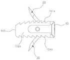
도 1 은 본 발명 케이지의 사시도,
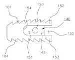
도 2 는 본 발명 케이지의 측면도,
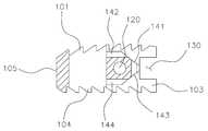
도 3 은 본 발명 케이지의 A-A' 선 단면도,
도 4 는 본 발명 케이지의 분해사시도,
도 5 는 본 발명 케이지의 본체의 상세도로서, 도 5a 는 평면도, 도 5b 는 측면도, 도 5c 는 B-B' 선 단면도, 도 5d 는 정면도,
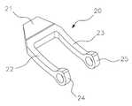
도 6 은 본 발명 케이지의 상부 스파이크의 상세도로서, 도 6a 는 사시도, 도 6b 는 평면도, 도 6c 는 C-C'선 단면도,
도 7 은 본 발명 케이지의 하부 스파이크의 상세도로서, 도 7a 는 사시도, 도 7b 는 평면도, 도 7c 는 D-D'선 단면도,
도 8 은 본 발명 케이지의 클립의 상세도로서, 도 8a 는 사시도, 도 8b 는 평면도, 도 8c 는 E-E'선 단면도, 도 8d 는 저면도,
도 9 및 도 10 은 본 발명 케이지의 상부 스파이크와 하부 스파이크가 클립과 결합한 상태의 도면으로서, 도 9a 는 상부 스파이크와 하부 스파이크의 미전개상태의 사시도, 도 9b 는 F-F' 선 단면도, 도 10a 는 상부 스파이크와 하부 스파이크의 전개상태의 사시도, 도 10b 는 G-G' 선 단면도,
도 11 은 본 발명 케이지의 가이드블럭의 상세도로서, 도 10a 는 사시도, 도 10b 는 평면도, 도 10c 는 정면도,
도 12 는 본 발명 케이지의 작동상태를 나타내는 도면으로서, 도 12a 는 클립의 진입시의 사시도, 도 12b 는 클립의 진입시의 평면도, 도 12c 는 스파이크 미전개상태의 H-H' 선 단면도, 도 12d 는 스파이크 전개상태의 단면도,
도 13 은 본 발명 케이지를 시술하기 위한 삽입기구를 나타낸 것으로서, 도 13a 은 사시도, 도 13b 는 평면도, 도 13c 는 스파이크 미전개상태의 측면도, 도 13d 는 스파이크 전개상태의 측면도,
도 14 는 본 발명 케이지가 추간판 제거 부위에 시술된 상태를 나타내는 단면도이다.1 is a perspective view of a cage of the present invention,
2 is a side view of the cage of the present invention,
3 is a cross-sectional view taken along line AA 'of the cage of the present invention,
4 is an exploded perspective view of the cage of the present invention,
5B is a side view, FIG. 5C is a sectional view taken along line BB ', FIG. 5D is a front view, and FIG. 5B is a side view of the cage.
6A is a perspective view, FIG. 6B is a plan view, FIG. 6C is a cross-sectional view taken along the line C-C ', FIG. 6C is a detailed view of an upper spike of the cage of the present invention,
7A is a perspective view, FIG. 7B is a plan view, FIG. 7C is a sectional view taken along a line D-D 'in FIG. 7A,
8A is a perspective view, FIG. 8B is a plan view, FIG. 8C is a sectional view taken along the line E-E ', FIG. 8D is a bottom view,
FIG. 9A is a perspective view of the upper spike and the lower spike in an undeveloped state, FIG. 9B is a sectional view of the FF 'line, FIG. 10A is a cross-sectional view of the upper spike and the lower spike, FIG. 10B is a sectional view taken along line GG 'of FIG.
Fig. 11 is a detailed view of a guide block of the cage of the present invention, wherein Fig. 10A is a perspective view, Fig. 10B is a plan view, Fig. 10C is a front view,
12B is a plan view of the clip on entry; FIG. 12C is a sectional view of the HH 'line in the unspike unfolded state; FIG. 12D is a cross- Sectional view of the state,
Fig. 13 is a perspective view of the cage of the present invention. Fig. 13A is a perspective view, Fig. 13B is a plan view, Fig. 13C is a side view of the unspiked state,
FIG. 14 is a sectional view showing a state where the cage of the present invention is put on the disc removal region.
이하, 도면을 참조하여 본 발명의 스파이크를 가진 케이지의 구성을 상세하게 설명한다.Hereinafter, the structure of a cage having a spike of the present invention will be described in detail with reference to the drawings.
단, 개시된 도면들은 당업자에게 본 발명의 사상이 충분하게 전달될 수 있도록 하기 위한 예로서 제공되는 것이다. 따라서, 본 발명은 이하 제시되는 도면들에 한정되지 않고 다른 태양으로 구체화될 수도 있다.It is to be noted, however, that the disclosed drawings are provided as examples for allowing a person skilled in the art to sufficiently convey the spirit of the present invention. Accordingly, the present invention is not limited to the following drawings, but may be embodied in other forms.
또한, 본 발명 명세서에서 사용되는 용어에 있어서 다른 정의가 없다면, 본발명이 속하는 기술 분야에서 통상의 지식을 가진 자가 통상적으로 이해하고 있는의미를 가지며, 하기의 설명 및 첨부 도면에서 본 발명의 요지를 불필요하게 흐릴 수 있는 공지 기능 및 구성에 대한 상세한 설명은 생략한다.
In addition, unless otherwise defined, the terms used in the description of the present invention have the same meaning as commonly understood by one of ordinary skill in the art to which the present invention belongs. In the following description and the accompanying drawings, A detailed description of known functions and configurations that may be unnecessarily blurred is omitted.
도 1 은 본 발명 케이지의 사시도이고, 도 2 는 본 발명 케이지의 평면도, 도 3 은 본 발명 케이지의 A-A' 선 단면도이다.Fig. 1 is a perspective view of the cage of the present invention, Fig. 2 is a plan view of the cage of the present invention, and Fig. 3 is a sectional view taken along the line A-A 'of the cage of the present invention.
도면을 참조하면, 본 발명 케이지(1)는 본체(10)와, 상기 본체(10) 내부로 진입하는 클립(50)과, 상기 클립(50)에 결합되어 클립(50)의 진입에 의하여 상부 및 하부로 각각 돌출하도록 전개되는 상부 스파이크(spike)(20) 및 하부 스파이크(30)와, 상기 본체(10)에 결합되어 상기 클립(50)의 진입을 안내하는 가이드블럭(40)을 포함하여 구성된다.Referring to the drawings, the
상기와 같이 본체(10)의 상부 및 하부로 전개된 상부 스파이크(20) 및 하부 스파이크(30)는 케이지(1) 상하에 위치하는 경추 또는 척추의 상측과 하측 추체(推體)들에 각각 걸려짐으로써 케이지(1)가 경추 또는 척추의 추체 사이에 고정되어 락킹되도록 하는 기능을 수행한다.The
상기 케이지(1)의 본체(10)는 상면(101)과 양측면(102), 정면(103), 저면(104), 배면(105)으로 이루어진 육면체 형상으로서, 본체(10)의 모서리 부분은 곡면으로 처리되어 있다.The
그리고, 도 2 에 도시된 바와 같이, 본체(10)에는 상면(101)과 저면(104)을 관통하는 골 융착공(110)이 형성되고, 상기 케이지(1)의 본체(10)에 상기 정면(103)부분으로부터 클립(50)이 삽입되는 개구를 가지는 공간부인 채널부(130)가 형성된다.2, the
또한, 상기 본체(10)의 내부에는 채널부(130)를 통하여 진입한 클립(50)에 결합된 상부 스파이크(20)와 하부 스파이크(30)가 각각 상방 및 하방으로 전개될 경우 그들의 이동을 안내하는 경사부(140)가 형성되며, 상기 경사부(140)의 상부는 상기 상부 스파이크(20)와 하부 스파이크(30)가 본체(10) 외부로 전개될 수 있도록 개구되어 있다. 상기 경사부(140)의 보다 상세한 구성은 후술한다.When the
또한, 도 3 에 도시된 바와 같이, 본체(10)의 상면(101) 및 저면(104)에는 케이지(1)가 경추 또는 척추의 추체들 사이에 삽입될 때, 상하측의 추체들과의 접촉성을 보다 양호하게 하기 위하여 톱니체(101a,104a)가 각각 형성된다.
3, when the
도 4 는 본 발명 케이지의 분해사시도이다.4 is an exploded perspective view of the cage of the present invention.
도 4 의 분해사시도에 도시된 바와 같이, 본체(10)의 정면(103)에 가이드블럭(40)이 결합된다.The
상기 가이드블럭(40)의 좌측 및 우측에 각각 형성된 좌측바(42)와 우측바(43)가 각각 본체(10)의 좌측 및 우측 측면(102)에 형성된 거치홈(151)에 내삽되고, 가이드블럭 결합핀(61)이 가이드블럭(40)의 좌측바(42)와 우측바(43)에 각각 형성된 통공(44)과 본체(10)의 좌측 측면으로부터 우측 측면(102)을 수직으로 관통하는 삽입공(120)을 관통함으로써 본체(10)와 가이드블럭(40)이 상호 결합된다.The
또한, 상기와 같이 본체(10)와 가이드블럭(40)이 결합된 상태에서 상부 스파이크(20)와 하부 스파이크(30)가 결합된 상태의 클립(50)이 상기 가이드블럭(40)의 진입구(46)를 통하여 본체(10) 내부로 진입한다.The
그리고, 진입한 클립(50)에 결합된 상부 스파이크(20)와 하부 스파이크(30)는 본체(10)의 내부에 형성된 경사부(140)의 상부경사면(141)과 하부경사면(143)을 따라서 안내되어 각각 상방 및 하방으로 이동되면서 본체(10)의 상측 및 하측의 외부로 돌출되도록 전개된다.The
이때, 상기 상부 스파이크(20) 및 하부 스파이크(30)는 클립 결합핀(61)에 의하여 상기 클립(50)에 각각 결합된다.At this time, the
상기와 같이 결합되는 본 발명 케이지(1)의 각 구성요소를 이하에서 보다 상세하게 설명하기로 한다.
The respective components of the
도 5 는 본 발명 케이지의 본체의 상세도로서, 도 5a 는 평면도, 도 5b 는 측면도, 도 5c 는 B-B' 선 단면도, 도 5d 는 정면도이다.Fig. 5 is a detailed view of the main body of the cage of the present invention, wherein Fig. 5A is a plan view, Fig. 5B is a side view, Fig. 5C is a sectional view taken along line B-B 'and Fig.
전술한 바와 같이, 본 발명 케이지(1)의 본체(10)는 상면(101)과 양측면(102), 정면(103), 저면(104), 배면(105)으로 이루어진 육면체 형상이며, 상면(101)과 저면(104)을 관통하는 골 융착공(110)이 형성되고, 상기 케이지(1)의 본체(10)의 정면(103)으로부터 본체(10)의 중앙부분까지 상기 클립(50)이 삽입되어 고정되는 공간부인 채널부(130)가 형성된다.As described above, the
상기 본체(10)의 내부에는 상기 채널부(130)를 통하여 진입한 클립(50)에 결합된 상부 스파이크(20)와 하부 스파이크(30)가 각각 상방 및 하방으로 전개될 경우 그들의 이동을 안내하는 경사부(140)가 형성되고, 상기 경사부(140)의 상부 및 하부는 상기 상부 스파이크(20)와 하부 스파이크(30)가 본체(10) 외부로 전개될 수 있도록 개구된다.The
또한, 상기 경사부(140)는 상부 스파이크(20)의 상방으로의 이동을 안내하는 상부경사면(141)이 형성되고, 상기 상부경사면(141)의 말단에는 상부 평면(142)이 형성된다.The
마찬가지로, 상기 경사부(140)는 하부 스파이크(30)의 하방으로의 이동을 안내하는 하부경사면(143)이 형성되고, 상기 하부경사면(143)의 말단에는 하부 평면(142)이 형성된다.Similarly, the
그리고, 상기 경사부(140)의 상부경사면(141)과 하부경사면(142)이 연결되는 부분에 일정한 폭을 가진 돌출면(146)이 형성되고, 이 돌출면(146)에 클립(50)의 베이스(57)의 내벽면이 걸려지면서 채널부(130)로 진입한 클립(50)의 진입이 정지되게 된다.A protruding
또한, 상기 경사부(140)의 좌측 및 우측 측면에는 각각 본체(10)의 상면(101) 및 저면(104)과 단차지게 형성된 내벽면(145)이 형성된다.Each of the left and right side surfaces of the
상기 내벽면(145)의 외측으로 상기 가이드블럭(40)의 좌측바(42)와 우측바(43)이 각각 거치되는 거치홈(151)이 형성되며, 상기 거치홈(151)은 상부벽(152)과 하부벽(153) 및 측벽(154)으로 이루어진 본체(10) 측면(102)에 각각 형성된 공간부이다.A mounting
상기와 같이 이루어지는 본 발명의 상기 케이지(1)의 본체(10)의 재질은 일반적으로 티타늄, 지르코늄, 산화지르코늄, 하프늄, 백금, 로듐, 니오븀, 외과용 스테인리스강, CoCr(코발트크롬)-강, 탄탈륨과 같은 금속 또는 금속 합금으로 이루어지거나, 섬유강화플라스틱, 폴리에테르에테르케톤(PEEK), 폴리머로서 이루진다. 나아가, 알루미늄, 의료용 강, 금과 같은 금속이 상기 금속 합금에 추가될 수도 있다.The material of the
바람직하게는, 상기 본체(10)의 재질로서 가공성과 내구성이 우수한 폴리에테르에테르케톤(PEEK)이 사용되는 것이 좋다.Preferably, polyether ether ketone (PEEK), which is excellent in workability and durability, is used as the material of the
상기 본체(10)에 형성된 골융착공(110)은, 케이지(1)의 시술을 위하여 환자의 장골에서 채취된 자가 이식된 뼈조각들로 채워질 수 있는데, 이 골융착공(110)에 채워진 뼈 조각들은 시술후 시간이 경과되면서 케이지를 관통하여 조직 생장이 일어나 환부의 추간 원판의 척추나 경추와의 융합을 가능하게 하는 기능을 한다.The
또한, 가이드블럭(40)을 본체(10)와 결합시키는 가이드블럭 결합핀(60)의 체결을 위하여 상기 본체(10)의 좌측 및 우측 측면(102)을 관통하는 삽입공(120)이 형성된다.
An
도 6 은 본 발명 케이지의 상부 스파이크의 상세도, 도 7 은 본 발명 케이지의 하부 스파이크의 상세도, 도 8 은 본 발명 케이지의 클립의 상세도이다.Fig. 6 is a detailed view of an upper spike of the cage of the present invention, Fig. 7 is a detailed view of a lower spike of the cage of the present invention, and Fig. 8 is a detailed view of a clip of the present invention cage.
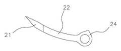
도 6a 내지 도 6c 를 참조하면, 본 발명 케이지(1)의 클립(50)에 결합되는 상부 스파이크(20)는, 말단이 첨단면을 이루는 상부 날(blade)(21)을 이루고 있으며, 상부 날(21)의 양측으로 하방으로 경사지게 연장된 암(22,23)이 각각 형성되고, 각 암(22,23)의 말단에는 클립(50)과의 결합을 위한 클립 결합핀(61)이 삽입되는 체결공(24,25)이 각각 형성된다.6A through 6C, the
상기와 같이 이루어지는 상부 스파이크(20)는 상기 체결공(24,25)으로부터 상방으로 상승하는 각도로 이루어져 있으며, 이러한 형상으로 인하여 본 발명 케이지(1)가 경추 또는 척추의 척추골의 상측 및 하측 추체들 사이에 삽입되었을 때, 상승하는 각도로 이루어진 상부 날(21)의 첨단면이 상측 추체의 내부로 요입되어 상측 추체에 걸려지면서 케이지(1)가 공고하게 삽입될 수 있게 된다.The
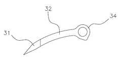
또한, 도 7a 내지 도 7c 를 참조하면, 상기 상부 스파이크(20)와 마찬가지로, 본 발명 케이지(1)의 클립(50)에 결합되는 하부 스파이크(30)는, 말단이 첨단면을 이루는 하부 날(blade)(31)을 이루고 있으며, 하부 날(31)의 양측으로 상방으로 경사지게 연장된 암(32,33)이 각각 형성되고, 각 암(32,33)의 말단에는 클립(50)과의 결합을 위한 클립 결합핀(61)이 삽입되는 체결공(34,35)이 각각 형성된다.7A-7C, similar to the
상기와 같이 이루어지는 하부 스파이크(30)는 상기 체결공(34,35)으로부터 하방으로 하강하는 각도로 이루어져 있으며, 이러한 형상으로 인하여 본 발명 케이지(1)가 경추 또는 척추의 척추골의 상측 및 하측 추체들 사이에 삽입되었을 때, 하강하는 각도로 이루어진 하부 날(31)의 첨단면이 하측 추체의 내부로 요입되어 하측 추체에 걸려지면서 상기 상부 스파이크(20)와 더불어 케이지(1)가 공고하게 삽입될 수 있게 된다.The
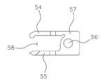
또한, 도 8a 내지 도 8d 를 참조하면, 케이지(1)의 상부 스파이크(20) 및 하부 스파이크(30)를 결합시키는 클립(50)은, 베이스(57)의 전방에 클립(50)을 본체(10) 내부로 미는 작동을 하는 후술할 삽입기구(200)와 접촉되는 평판 형상의 우측 걸림턱(51)과 좌측 걸림턱(52)이 형성되고, 베이스(57)의 후방 상단에는 클립(50)이 본체(10) 내부로 진입한 경우, 본체(10)의 경사부(140)의 상부 평면(142)상에 슬라이드되어 거치되도록 연장된 우측 리브(rib)(53)와 좌측 리브(54)가 각각 형성된다.8A to 8D, a
또한, 상기 클립(50)의 후방 하단에는 클립(50)이 본체(10) 내부로 진입한 경우, 본체(10)의 경사부(140)의 하부 평면(144) 상에 슬라이드되어 거치되도록 연장된 하부 리브(55)가 형성된다.When the
또한, 상기 상부 스파이크(20) 및 하부 스파이크(30)와의 결합을 위한 클립 결합핀(61)의 체결을 위하여 상기 클립(50)의 베이스(57)를 관통하는 관통공(56)이 형성된다.
A through
도 9 및 도 10 은 본 발명 케이지의 상부 스파이크와 하부 스파이크가 클립과 결합한 상태의 도면이다.Figs. 9 and 10 show a state in which the upper spike and the lower spike of the inventive cage are engaged with a clip. Fig.
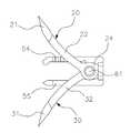
도 9a 및 도 9b 에 도시된 바와 같이, 상부 스파이크(20)의 양측 암(22,23)의 내측으로 하부 스파이크(30)를 위치시킨 후, 상부 스파이크(20)의 체결공(24,25)과 하부 스파이크(30)의 체결공(34,35)을 정렬시킨 상태에서 상기 클립(50)의 베이스(57)에 형성된 관통공(56)에 각 스파이크의 체결공(24,25,34,35)을 정렬시켜 클립 결합핀(61)을 각 체결공(24,25,34,35)과 클립(50)의 관통공(56)으로 통과시켜 상부 스파이크(20) 및 하부 스파이크(30)를 클립(50)에 결합시킨다.The lower spikes 30 are positioned inwardly of the
따라서, 상기와 같이 클립(50)에 결합된 상부 스파이크(20)와 하부 스파이크(30)는 도 10a 및 도 10b 에 도시된 바와 같이, 상부 스파이크(20)가 클립(50)과 결합한 체결공(24,25)을 중심으로 그 상부 날(21)이 상하 방향으로 회동 가능하게 작동되며, 마찬가지로, 하부 스파이크(30)도 체결공(34,35)를 중심으로 그 하부 날(31)이 상하방향으로 회동 가능하게 작동된다.
The
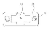
도 11 은 본 발명 케이지의 가이드블럭의 상세도이다.11 is a detailed view of a guide block of the cage of the present invention.
도 11a 의 사시도, 도 11b 의 평면도, 도 11c 의 정면도를 참조하면, 본 발명의 가이드블럭(40)은 상기 본체(10)에 결합되어 상기 클립(50)의 진입을 안내하는 기능을 수행하며, 구체적으로는, 본체(10)의 정면(103)을 마감하는 평판 형상의 전면판(41)과, 상기 전면판(41)의 양측면 단부에서 후방으로 연장형성되는 좌측 바(bar)(42) 및 우측바(43)와, 전술한 가이드블럭결합핀(60)이 삽입될 수 있도록 상기 좌측바(42) 및 우측바(43)에 각각 관통 형성된 통공(44)이 각각 형성되고, 상기 전면판(41)의 중앙에 상기 클립(50)이 진입하는 개구를 이루는 진입구(46)가 형성된다.11B, 11B, and 11C, the
그리고, 전술한 바와 같이, 상기 가이드블럭(40)의 좌측바(42)와 우측바(43)가 본체(10)의 좌측 및 우측 측면(102)에 형성된 거치홈(151)에 내삽된 상태에서, 좌측바(42)의 통공(44)으로 진입하는 가이드블럭 결합핀(60)이 본체(10)의 삽입공(120)을 관통하여 우측바(43)의 통공(44)까지 체결됨으로써 본체(10)와 가이드블럭(40)이 상호 결합된다.When the
한편, 상기 가이드블럭(40)의 전면판(41) 상에는 후술할 삽입기구(200)의 헤드(210)에 고정된 결합나사(미도시)가 삽입되는 요입공(45)이 적어도 하나 이상 형성된다.
On the
상기와 같이 구성되는 본 발명 케이지(10)의 작동을 도 12 의 작동상태도를 참조하여 상세하게 설명한다.The operation of the
도 12a 는 클립의 진입시의 사시도, 도 12b 는 클립의 진입시의 평면도, 도 12c 는 스파이크 미전개상태의 H-H' 선 단면도, 도 12d 는 스파이크 전개상태의 단면도이다.12A is a perspective view at the time of entering the clip, FIG. 12B is a plan view at the time of entering the clip, FIG. 12C is a sectional view taken along the line H-H 'in the unspike unfolded state, and FIG.
본 발명 케이지(10)는 상기 상부 스파이크(20)와 상기 하부 스파이크(30)가 각각 추간판 제거 부위의 경추골 또는 척추골의 상하측 추체들에 걸려지면서 고정되도록 작동된다.The
먼저, 도 12a 및 도 12b 에 도시된 바와 같이, 본체(10)와 가이드블럭(40)을 결합시키고 이 상태에서 상부 스파이크(20)와 하부 스파이크(30)가 결합된 상태의 클립(50)의 우측 걸림턱(51)과 좌측 걸림턱(52)을 후술할 삽입기구(200) 등의 도구를 이용하여 밀어서 클립(50)을 상기 가이드블럭(40)의 진입구(46)를 통하여 본체(10) 내부로 진입시킨다.12A and 12B, when the
이러한 클립(50)의 진입 초기의 상태에서는 상기 상부 스파이크(20)와 하부 스파이크(30)의 상부 날(21)과 하부 날(31)이 본체(10) 내부의 경사부(140)의 상부 경사면(141)과 하부 경사면(143)의 초입까지만 도달하면서 도 12c 에 도시된 바와 같이 본체(10)의 상면(101)과 저면(104) 외부로 미전개된 상태에 있게 된다.The
이어서, 상기와 같은 진입한 클립(50)을 본체(10) 내부로 더 밀어주게 되면,도 12d 에 도시된 바와 같이 클립(50)에 결합된 상부 스파이크(20)와 하부 스파이크(30)가 본체(10)의 내부에 형성된 경사부(140)의 상부경사면(141)과 하부경사면(143)을 따라서 안내되면서 각각 상방 및 하방으로 이동되어 본체(10)의 상면(101)과 저면(104) 외부로 돌출되고, 클립(50)의 베이스(57)가 상기 경사부(140)의 중앙에 형성된 돌출면(146)에 의하여 걸려질 때까지 상부 스파이크(20)와 하부 스파이크(30)가 상방 및 하방으로 각각 이동되면서 전개된다.12d, the
이때, 상기 클립(50)의 우측리브(53) 및 좌측리브(54)는 경사부(140)의 상부 평면(142) 상으로 슬라이드되어 거치되고, 상기 클립(50)의 하부 리브(55)는 경사부(140)의 하부 평면(144) 상으로 슬라이드되어 거치되게 된다.At this time, the
따라서, 본 발명 케이지(1)는 상기와 같은 전개 작동을 수행하는 상부 스파이크와 하부 스파이크들에 의하여 종래 좁은 추간 공간상에서 플레이트를 스크류로 고정하는 어렵고 불편한 시술 과정을 생략할 수 있어 시술의 편의성을 향상시키고 수술의 안정성을 제고시킬 수 있게 되는 것이다.
Therefore, the
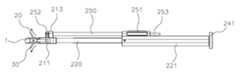
도 13 은 본 발명 케이지를 시술하기 위한 삽입기구를 나타낸 것이다.13 shows an insertion mechanism for performing the cage of the present invention.
상기 삽입기구(200)는 상술한 바와 같은 본 발명 케이지(1)의 본체(10) 내부로 상부 스파이크(20)와 하부 스파이크(30)를 결합시킨 상태의 클립(50)을 보다 보다 안정적으로 삽입시키기 위하여 사용된다.The inserting
구체적으로, 도 13a 의 사시도, 도 13b 의 평면도, 도 13c 의 스파이크 미전개상태의 측면도를 참조하면, 본 발명 케이지(1)를 위한 삽입기구(200)는 가이드블럭(40)의 전면판(41)의 요입공(45)에 삽입되는 결합나사(미도시)에 의하여 가이드블럭(40)과 체결되는 헤드(210)을 가지고 있다.More specifically, referring to a perspective view of FIG. 13A, a plan view of FIG. 13B, and a side view of the unspiked state of FIG. 13C, the
상기 헤드(210)는 대략 육면체 형상으로서, 헤드(210)의 좌측에 제 1 하부지지봉(220)의 일측이 결합되고 헤드(2100의 우측에 제 2 하부지지봉(230)이 일측이 각각 결합된다.One end of the first
또한, 상기 제 1 하부지지봉(220)과 제 2 하부지지봉(230) 사이에 상기 클립(50)을 본체(10) 내부로 밀어주는 보스(boss)(243)을 일측 말단에 형성한 밀대(240)가 위치된다.A
상기 밀대(240)는 그 타측 말단에 형성된 누름판(241)과, 누름판(242)으로부터 연장된 봉체(242)와, 상기 봉체(242)와 상기 보스(243)을 연결하는 결합구(244)로 이루어진 것으로서, 누름판(241)을 전방으로 밀게 되면, 봉체(242)를 통하여 결합구(244)에 연결된 보스(243)가 전방으로 이동되면서 도 13d 와 같이 클립(50)을 케이지(1)의 본체(10) 내부로 진입시켜 상부 스파이크(20) 및 하부 스파이크(30)가 각각 본체(10)의 상면과 저면 외부로 돌출 전개되는 것이다.The
이러한 작동을 위하여, 상기 헤드(210)는 상기 제 1 하부지지봉(220)이 결합되는 좌측헤드(211)와 상기 제 2 하부지지봉(230)이 결합되는 우측 헤드(212)와, 상기 밀대(240)의 보스(243)는 상기 좌측헤드(211)와 우측헤드(212)의 사이에서 전방 또는 후방으로 이동가능하게 체결되며, 상기 제 1 하부지지봉(220)의 타측 말단 및 상기 제 2 하부지지봉(230)의 말단은 상기 밀대(240)의 봉체(242)가 거치되는 밀대가이드(221)의 내부로 내삽된다.For this operation, the
또한, 상기 삽입기구(200)의 헤드(210)의 상측으로 상부지지봉(250)의 일측 말단이 내삽되는 상부헤드(213)가 형성되며, 상부지지봉(250)의 타측 말단은 상기 밀대가이드(221)의 상부에 형성된 상부지지봉가이드(251)의 내부로 내삽된다. 아울러, 상기 상부지지봉(250)의 일측 말단에는 지지체(252)가 취부된다.An
상기 상부지지봉(250)은 클립(50) 삽입시 케이지(1)가 시술되는 척추 또는 경추의 상측 추체와 접촉하여 삽입기구(400)의 고정성 및 안정성을 향상시키는 기능을 수행한다.
The
도 14 은 상기와 같은 본 발명 케이지(10)의 시술 상태를 나타낸 것으로서, 경추 또는 척추골의 상측 추체(D1)와 하측 추체(D2) 사이에 본 발명 케이지(1)가 위치된 후 상술한 바와 같은 삽입기구(200)를 통하여 클립(50)을 본체(10) 내부로 진입시켜 상부 스파이크(20) 및 하부 스파이크(30)를 본체(10)의 상면(101) 및 저면(104)의 외부로 돌출시킴으로써, 돌출된 스파이크들(20,30)의 말단의 상부 날(21)과 하부 날(31)의 첨단부가 케이지(1) 상하에 위치하는 상측 추체(D1)과 하측 추체(D2)에 걸려짐으로써 케이지(1)가 추체들(D1,D2) 사이에 고정되어 락킹되는 시술 상태를 도시하고 있다.14 shows the state of operation of the
실제 시술시에는 상기 클립(50)을 본체(10)로 진입시키기 위하여, 밀대(240)의 타측 말단에 형성된 누름판(241)을 수술용 망치(미도시)등으로 가격해 가면서 클립(50)을 본체(10) 내부로 신중하게 천천히 진입시키게 된다.The
따라서, 본 발명의 케이지(1)는 도시된 바와 같이 상측 추체(D1)와 하측 추체(D2)들 사이에서 이들 추체(D1,D2)들의 내측 후방으로 상부 스파이크(20)와 하부 스파이크(30)가 공고하게 고정됨으로써, 종래의 케이지들이 가지고 있는 스크류나 플레이트의 일부 부분이 케이지가 설치된 추간판 제거부위의 척추나 경추를 통과하는 신경조직과 혈관조직과 간섭을 일으킬 가능성을 대폭 감소시킬 수 있게 된다.
The
이상의 설명에서 본 발명의 스파이크를 가진 케이지의 구성을 첨부된 도면을 참조하여 상세하게 설명하였으나, 본 발명은 당업자에 의하여 다양한 수정, 변경 및 치환이 가능하고, 이러한 수정, 변경 및 치환은 본 발명의 보호범위에 속하는 것으로 해석되어야 한다.While the present invention has been particularly shown and described with reference to exemplary embodiments thereof, it is evident that many alternatives, modifications and variations will be apparent to those skilled in the art in light of the above teachings. Should be interpreted as falling within the scope of protection.
* 도면의 주요 부분에 대한 부호의 설명 *
1; 케이지
10; 본체
101; 상면 102; 측면
103; 정면104; 저면
105; 배면 110; 골 융착공
101a,104a; 톱니체
120; 삽입공
130; 채널부
140; 경사부
141; 상부 경사면142; 상부 평면
143; 하부 경사면144; 하부 평면
145; 내벽면146; 돌출면
151; 거치홈152; 상부벽
153; 하부벽154; 측벽
20; 상부 스파이크
21; 상부날22,23; 암
24,25; 체결공
30; 하부 스파이크
31; 하부날32,33; 암
34,35; 체결공
40; 가이드블럭
41; 전면판
42; 좌측 바 43; 우측 바
44; 통공45; 요입공
46; 진입구
50; 클립
51; 우측 걸림턱52; 좌측 걸림턱
53; 우측 리브54; 좌측 리브
55; 하부 리브56; 관통공
57; 베이스
60; 가이드블럭 결합핀
61; 클립 결합핀
200; 삽입기구
210; 헤드
211; 좌측 헤드212; 우측 헤드
213; 상부 헤드
220; 제 1 하부지지봉
221; 밀대 가이드
230; 제 2 하부지지봉
240; 밀대
241; 누름판242; 봉체
243; 보스244; 결합구
250; 상부지지봉
251; 상부지지봉 가이드252; 지지체
D1; 상부뼈
D2; 하부뼈Description of the Related Art [0002]
One; Cage
10; main body
101;
103;
105; Back
101a, 104a; Sawtooth
120; Insert ball
130; Channel portion
140; Inclined portion
141; An upper
143;
145;
151; A mounting
153;
20; Upper spike
21; Upper edges 22, 23; cancer
24,25; Fastener
30; Bottom spike
31;
34,35; Fastener
40; Guide block
41; Front plate
42;
44; Through
46; Entry
50; Clip
51;
53;
55;
57; Base
60; Guide block coupling pin
61; Clip coupling pin
200; Insertion mechanism
210; head
211; A
213; Upper head
220; The first lower support rod
221; Pusher guide
230; The second lower support rod
240; Plunger
241; A
243;
250; Upper support rod
251; Upper
D1; Upper bone
D2; Lower bone
Claims (9)
Translated fromKorean상면(101)과 양측면(102), 정면(103), 저면(104), 배면(105)으로 이루어진 육면체 형상으로 이루어진 본체(10);
상기 본체(10) 내부로 진입하도록 작동하는 클립(50);
상기 클립(50)에 결합되어 상기 클립(50)의 진입에 의하여 상기 본체(10)의 상면(101)의 외부로 돌출되도록 전개되는 상부 스파이크(20);
상기 클립(50)에 결합되어 상기 클립(50)의 진입에 의하여 상기 본체(10)의 저면(104)의 외부로 돌출되도록 전개되는 하부 스파이크(30);
상기 본체(10)에 결합되어 상기 클립(50)의 진입을 안내하는 가이드블럭(40); 을 포함하여 구성되고,
상기 본체(10)에는 상면(101)과 저면(104)을 관통하는 골 융착공(110)이 형성되고,
상기 본체(10)의 정면(103)으로부터 중앙 부분까지 상기 클립(50)이 삽입되는 공간부인 채널부(130)가 형성되고,
상기 본체(10)의 내부에는 상기 상부 스파이크(20)와 하부 스파이크(30)의 이동을 안내하는 경사부(140)가 형성되고,
상기 본체(10)의 양측면(102)에는 상기 가이드블럭(40)의 좌측바(42)와 우측바(43)가 각각 거치되는 거치홈(151)이 형성되고,
상기 상부 스파이크(20)는,
말단이 첨단면을 이루는 상부 날(21)과, 상기 상부 날(21)의 양측으로 하방으로 경사지게 연장된 각각의 암(22,23)과, 상기 각각의 암(22,23)의 말단에 형성되어 클립 결합핀(61)이 삽입되는 체결공(24,25)을 포함하여 구성되고,
상기 하부 스파이크(30)는,
말단이 첨단면을 이루는 하부 날(31)과, 상기 하부 날(31)의 양측으로 상방으로 경사지게 연장된 각각의 암(32,33)과, 상기 각각의 암(32,33)의 말단에 형성되어 클립 결합핀(61)이 삽입되는 체결공(34,35)을 포함하여 구성되는 것을 특징으로 하는 스파이크를 가진 케이지.
In a cage which is performed between the vertebrae of the cervical vertebrae or vertebrae,
A body 10 having a hexahedron shape composed of an upper surface 101 and two side surfaces 102, a front surface 103, a bottom surface 104 and a rear surface 105;
A clip (50) operative to enter into the body (10);
An upper spike 20 coupled to the clip 50 and deployed to protrude out of the upper surface 101 of the body 10 upon entry of the clip 50;
A lower spike 30 coupled to the clip 50 and deployed to protrude out of the bottom surface 104 of the body 10 upon entry of the clip 50;
A guide block (40) coupled to the body (10) and guiding the entry of the clip (50); And,
The main body 10 is provided with an osseointegration hole 110 passing through the top surface 101 and the bottom surface 104,
A channel part 130 as a space part through which the clip 50 is inserted is formed from a front surface 103 of the main body 10 to a center part thereof,
An inclined portion 140 for guiding movement of the upper spike 20 and the lower spike 30 is formed in the main body 10,
Mounting grooves 151 are formed on both side surfaces 102 of the main body 10 to hold the left bar 42 and the right bar 43 of the guide block 40,
The upper spike (20)
(22, 23) extending obliquely downward to both sides of the upper blade (21), and a pair of arms (22, 23) formed at the ends of the arms And a coupling hole (24, 25) into which a clip coupling pin (61) is inserted,
The lower spike (30)
(32, 33) extending obliquely upward from both sides of the lower blade (31), and a pair of arms (32, 33) formed at the ends of the arms And a fastening hole (34, 35) into which a clip coupling pin (61) is inserted.
상부 스파이크(20)의 상방으로의 이동을 안내하는 상부경사면(141)이 형성되고, 상기 상부경사면(141)의 말단에는 상부 평면(142)이 형성되고,
하부 스파이크(30)의 하방으로의 이동을 안내하는 하부경사면(143)이 형성되고, 상기 하부경사면(143)의 말단에는 하부 평면(142)이 형성되는 것을 특징으로 하는 스파이크를 가진 케이지.
2. The apparatus according to claim 1, wherein the inclined portion (140)
An upper inclined surface 141 for guiding upward movement of the upper spike 20 is formed and an upper surface 142 is formed at the end of the upper inclined surface 141,
Characterized in that a lower inclined surface (143) for guiding movement of the lower spike (30) downward is formed and a lower plane (142) is formed at the end of the lower inclined surface (143).
베이스(57)의 전방에 평판 형상의 우측 걸림턱(51)과 좌측 걸림턱(52)을 형성하고, 상기 베이스(57)의 후방 상단에 상기 경사부(140)의 상부 평면(142)상에 슬라이드되어 거치되는 우측 리브(53)와 좌측 리브(54)가 각각 형성되고,
상기 베이스(57)의 후방 하단에는 상기 경사부(140)의 하부 평면(144)상에 슬라이드되어 거치되는 하부 리브(55)가 형성되고,
상기 클립(50)의 베이스(57)를 관통하는 관통공(56)이 형성되며 클립 결합핀(61)이 상기 관통공(56)에 삽입되는 구성을 특징으로 하는 스파이크를 가진 케이지.
The apparatus of claim 3, wherein the clip (50)
A right hooking tab 51 and a left hooking tab 52 are formed on the front side of the base 57 and are provided on the upper surface of the upper surface 142 of the inclined portion 140 at the rear upper end of the base 57 A right rib 53 and a left rib 54, which are slid and mounted, are respectively formed,
A lower rib 55 is formed at the lower rear end of the base 57 to be slid on the lower plane 144 of the inclined portion 140,
Wherein a through hole (56) is formed through the base (57) of the clip (50) and a clip coupling pin (61) is inserted into the through hole (56).
상기 경사부(140)의 상부경사면(141)과 하부경사면(142)이 연결되는 부분에 돌출면(146)이 형성하고,
상기 클립(50)이 본체(10) 내부로의 진입시 상기 베이스(57)의 내측에 상기 경사부(140)의 돌출면(146)이 걸려져 클립(50)의 진입이 정지되는 구성을 특징으로 하는 스파이크를 가진 케이지.
6. The method of claim 5,
A protruding surface 146 is formed at a portion where the upper inclined surface 141 and the lower inclined surface 142 of the inclined portion 140 are connected,
When the clip 50 moves into the main body 10, the projection surface 146 of the inclined portion 140 is hooked to the inside of the base 57 to stop the entry of the clip 50 Cage with spikes to do.
본체(10)의 정면(103)을 마감하는 평판 형상의 전면판(41)과,
상기 전면판(41)의 양측 단부에서 후방으로 연장형성되는 좌측 바(42) 및 우측바(43)와,
상기 좌측바(42) 및 우측바(43)에 각각 관통 형성되어 가이드블럭결합핀(60)이 삽입되는 통공(44)과,
상기 전면판(41)의 중앙에 상기 클립(50)이 진입하는 개구를 이루는 진입구(46)가 형성된 구성을 특징으로 하는 스파이크를 가진 케이지.
2. The apparatus of claim 1, wherein the guide block (40)
A front plate 41 having a flat plate shape for closing the front surface 103 of the main body 10,
A left bar 42 and a right bar 43 extending rearward from both side ends of the front plate 41,
A through hole 44 penetrating through the left bar 42 and the right bar 43 and inserted into the guide block engaging pin 60,
And an entry port (46) is formed at the center of the front plate (41) to form an opening through which the clip (50) enters.
상기 본체(10)의 상면(101) 및 저면(104)에 톱니체(101a,104a)가 각각 형성되는 것을 특징으로 하는 스파이크를 가진 케이지.
The method according to claim 1,
Wherein spikes (101a, 104a) are formed on the upper surface (101) and the lower surface (104) of the main body (10), respectively.
상기 가이드블럭(40)과 체결되는 헤드(210)가 형성되고,
상기 헤드(210)의 좌측에 제 1 하부지지봉(220)의 일측이 결합되고 헤드(210)의 우측에 제 2 하부지지봉(230)이 일측이 결합되고,
상기 제 1 하부지지봉(220)과 제 2 하부지지봉(230) 사이에서 상기 클립(50)을 본체(10) 내부로 밀어주기 위하여 전방 또는 후방으로 이동가능하게 결합된 보스(243)를 일측 말단에 형성한 밀대(240)가 결합되고,
상기 제 1 하부지지봉(220)의 타측 말단 및 상기 제 2 하부지지봉(230)의 말단은 상기 밀대(240)가 거치되는 밀대가이드(221)의 내부로 내삽되고,
상기 헤드(210)의 상측에 형성된 상부헤드(213)에 상부지지봉(250)이 결합된 구성을 특징으로 하는 삽입기구.An insertion mechanism (200) for inserting a clip (50) into a cage body (10) of any one of claims 1, 3, 5, 6, 7,
A head 210 coupled to the guide block 40 is formed,
One side of the first lower support rod 220 is coupled to the left side of the head 210 and the other side of the second lower support rod 230 is coupled to the right side of the head 210,
A boss 243 movably coupled forward or backward to push the clip 50 into the main body 10 between the first lower support bar 220 and the second lower support bar 230 is provided at one end The formed bar 240 is engaged,
The other end of the first lower support rod 220 and the end of the second lower support bar 230 are inserted into the inside of the pusher 221 on which the pusher 240 is mounted,
Wherein an upper support rod (250) is coupled to an upper head (213) formed on the upper side of the head (210).
Priority Applications (9)
| Application Number | Priority Date | Filing Date | Title |
|---|---|---|---|
| KR1020130108840AKR101555317B1 (en) | 2013-09-11 | 2013-09-11 | Cage having the spike |
| JP2014099388AJP2015054235A (en) | 2013-09-11 | 2014-05-13 | Spiked cage |
| BR102014018715ABR102014018715A2 (en) | 2013-09-11 | 2014-07-29 | spine cage |
| US14/460,536US9775722B2 (en) | 2013-09-11 | 2014-08-15 | Cage having spike |
| CN201610902564.3ACN107028689B (en) | 2013-09-11 | 2014-09-10 | A kind of fixed device and dorsal column system |
| CN201410456862.5ACN104414775B (en) | 2013-09-11 | 2014-09-10 | Vertebral cage with spikes |
| CH01377/14ACH708531B1 (en) | 2013-09-11 | 2014-09-11 | Intervertebral fusion cage. |
| US15/723,174US10765531B2 (en) | 2013-09-11 | 2017-10-03 | Cage having spike |
| US16/987,843US11484415B2 (en) | 2013-09-11 | 2020-08-07 | Cage having spike |
Applications Claiming Priority (1)
| Application Number | Priority Date | Filing Date | Title |
|---|---|---|---|
| KR1020130108840AKR101555317B1 (en) | 2013-09-11 | 2013-09-11 | Cage having the spike |
Publications (2)
| Publication Number | Publication Date |
|---|---|
| KR20150029880A KR20150029880A (en) | 2015-03-19 |
| KR101555317B1true KR101555317B1 (en) | 2015-10-06 |
Family
ID=52629923
Family Applications (1)
| Application Number | Title | Priority Date | Filing Date |
|---|---|---|---|
| KR1020130108840AExpired - Fee RelatedKR101555317B1 (en) | 2013-09-11 | 2013-09-11 | Cage having the spike |
Country Status (6)
| Country | Link |
|---|---|
| US (3) | US9775722B2 (en) |
| JP (1) | JP2015054235A (en) |
| KR (1) | KR101555317B1 (en) |
| CN (2) | CN107028689B (en) |
| BR (1) | BR102014018715A2 (en) |
| CH (1) | CH708531B1 (en) |
Cited By (2)
| Publication number | Priority date | Publication date | Assignee | Title |
|---|---|---|---|---|
| WO2019168243A1 (en)* | 2018-02-27 | 2019-09-06 | (주)엘앤케이바이오메드 | Integrated oblique vertebral fusion cage |
| US11058542B1 (en) | 2020-09-21 | 2021-07-13 | Randall F. Lee | System and method for joining boney structures |
Families Citing this family (41)
| Publication number | Priority date | Publication date | Assignee | Title |
|---|---|---|---|---|
| FR2897259B1 (en) | 2006-02-15 | 2008-05-09 | Ldr Medical Soc Par Actions Si | INTERSOMATIC TRANSFORAMINAL CAGE WITH INTERBREBAL FUSION GRAFT AND CAGE IMPLANTATION INSTRUMENT |
| WO2011080535A1 (en) | 2009-12-31 | 2011-07-07 | Lrd Medical | Anchoring device, intervertebral implant and implantation instrument |
| US9987142B2 (en) | 2012-08-31 | 2018-06-05 | Institute for Musculoskeletal Science and Education, Ltd. | Fixation devices for anterior lumbar or cervical interbody fusion |
| FR3005569B1 (en) | 2013-05-16 | 2021-09-03 | Ldr Medical | VERTEBRAL IMPLANT, VERTEBRAL IMPLANT FIXATION DEVICE AND IMPLANTATION INSTRUMENTATION |
| US9351847B2 (en)* | 2013-08-22 | 2016-05-31 | Globus Medical, Inc. | Interbody fusion devices with self-affixing mechanisms |
| KR101555317B1 (en) | 2013-09-11 | 2015-10-06 | 주식회사 솔고 바이오메디칼 | Cage having the spike |
| US9968464B2 (en)* | 2014-01-17 | 2018-05-15 | Spine Wave, Inc. | Spinal fusion system |
| FR3016793B1 (en) | 2014-01-30 | 2021-05-07 | Ldr Medical | ANCHORING DEVICE FOR SPINAL IMPLANT, SPINAL IMPLANT AND IMPLANTATION INSTRUMENTATION |
| FR3020756B1 (en) | 2014-05-06 | 2022-03-11 | Ldr Medical | VERTEBRAL IMPLANT, VERTEBRAL IMPLANT FIXATION DEVICE AND IMPLANT INSTRUMENTATION |
| US10433980B2 (en) | 2015-05-21 | 2019-10-08 | Globus Medical, Inc. | Device and method for deployment of an anchoring device for intervertebral spinal fusion |
| US10765532B2 (en) | 2015-05-21 | 2020-09-08 | Globus Medical, Inc. | Device and method for deployment of an anchoring device for intervertebral spinal fusion |
| US10433975B2 (en) | 2015-05-21 | 2019-10-08 | Globus Medical, Inc. | Device and method for deployment of an anchoring device for intervertebral spinal fusion |
| US10137005B2 (en)* | 2015-05-21 | 2018-11-27 | Globus Medical, Inc. | Device and method for deployment of an anchoring device for intervertebral spinal fusion |
| US10631997B2 (en) | 2015-05-21 | 2020-04-28 | Globus Medical, Inc. | Device and method for deployment of an anchoring device for intervertebral spinal fusion |
| JP6643364B2 (en)* | 2015-06-25 | 2020-02-12 | インスティテュート フォー マスキュロスケレタル サイエンス アンド エジュケイション,リミテッド | Interbody fusion device and system for implantation |
| US10258479B2 (en)* | 2015-08-15 | 2019-04-16 | Ldr Medical | Devices, methods, and systems to implant and secure a fusion cage or intervertebral prosthesis for spinal treatment |
| FR3048176A1 (en) | 2016-02-26 | 2017-09-01 | Ldr Medical | SPINAL ARTHRODESIS IMPLANT SYSTEM |
| US10098755B2 (en) | 2016-05-25 | 2018-10-16 | Genesys Spine | Stand alone interbody spinal system |
| US10307265B2 (en) | 2016-10-18 | 2019-06-04 | Institute for Musculoskeletal Science and Education, Ltd. | Implant with deployable blades |
| US10449060B2 (en) | 2016-10-25 | 2019-10-22 | Institute for Musculoskeletal Science and Education, Ltd. | Spinal fusion implant |
| US10405992B2 (en) | 2016-10-25 | 2019-09-10 | Institute for Musculoskeletal Science and Education, Ltd. | Spinal fusion implant |
| FR3058042B1 (en) | 2016-10-27 | 2021-12-10 | Ldr Medical | EXPANDABLE INTERVERTEBRAL IMPLANT |
| US9937055B1 (en) | 2016-11-28 | 2018-04-10 | Spine Wave, Inc. | Scoring implant trial and implant inserter for spinal fusion system |
| EP3354234B1 (en)* | 2017-01-27 | 2024-03-13 | Globus Medical, Inc. | Device for deployment of an anchoring device for intervertebral spinal fusion |
| US11672674B2 (en) | 2017-04-19 | 2023-06-13 | Life Spine Inc. | Implant with bone screw retention |
| EP3612138A1 (en)* | 2017-04-19 | 2020-02-26 | Life Spine, Inc. (a Delaware Corporation) | Stand-alone alif spine implants |
| EP3654875B1 (en)* | 2017-07-18 | 2024-08-28 | Blue Sky Technologies, LLC | Joint arthrodesis system |
| US10888435B2 (en) | 2017-10-05 | 2021-01-12 | Spine Wave, Inc. | Modular inserter for anterior cervical cage |
| US10925748B2 (en)* | 2018-01-25 | 2021-02-23 | Alliance Partners, Llc | Medical implant having an anchoring system and method of use thereof |
| US11944552B2 (en)* | 2018-03-08 | 2024-04-02 | Nexus Spine, LLC | Stand-alone interbody fusion |
| US10849758B2 (en) | 2018-08-22 | 2020-12-01 | Institute for Musculoskeletal Science and Education, Ltd. | Spinal fusion implant |
| KR102261812B1 (en)* | 2019-06-03 | 2021-06-08 | 경북대학교 산학협력단 | Spinal Fixation Device |
| US11883076B2 (en)* | 2019-10-01 | 2024-01-30 | Globus Medical, Inc | Intradiscal anchor fixation device and method |
| WO2021127635A1 (en) | 2019-12-19 | 2021-06-24 | FloSpine, LLC | Expandable intervertebral implant |
| US12144742B2 (en) | 2020-06-15 | 2024-11-19 | Foundation Surgical Group, Inc. | Implant system and methods of use |
| US11883300B2 (en) | 2020-06-15 | 2024-01-30 | Nofusco Corporation | Orthopedic implant system and methods of use |
| US11259936B2 (en) | 2020-06-15 | 2022-03-01 | Nofusco Corporation | Intravertebral implant system and methods of use |
| US11723778B1 (en) | 2021-09-23 | 2023-08-15 | Nofusco Corporation | Vertebral implant system and methods of use |
| WO2023285675A1 (en) | 2021-07-16 | 2023-01-19 | Blue Ocean Spine Gmbh | Adjustable intervertebral cage, associated instrument and manufacturing process therefor |
| US20230414374A1 (en)* | 2022-06-24 | 2023-12-28 | Joey Reglos | Interbody spacer with non-screw anchor |
| US12201530B2 (en)* | 2022-08-25 | 2025-01-21 | Orthopedic Designs North America, Inc. | Lumbar vertebrae fusion device with internal extension mechanism |
Citations (2)
| Publication number | Priority date | Publication date | Assignee | Title |
|---|---|---|---|---|
| US20120078371A1 (en) | 2010-09-23 | 2012-03-29 | Thomas Gamache | Fusion cage with in-line single piece fixation |
| US20130110242A1 (en)* | 2011-10-28 | 2013-05-02 | Incite Innovation | Spinal Interbody Device |
Family Cites Families (55)
| Publication number | Priority date | Publication date | Assignee | Title |
|---|---|---|---|---|
| FR2797179B1 (en) | 1999-08-03 | 2002-03-08 | Michel Gau | INTERVERTEBRAL NUCLEAR PROSTHESIS AND SURGICAL IMPLANTATION METHOD |
| FR2897259B1 (en) | 2006-02-15 | 2008-05-09 | Ldr Medical Soc Par Actions Si | INTERSOMATIC TRANSFORAMINAL CAGE WITH INTERBREBAL FUSION GRAFT AND CAGE IMPLANTATION INSTRUMENT |
| FR2808995B1 (en) | 2000-05-18 | 2003-02-21 | Aesculap Sa | INTERSOMATIC CAGE WITH UNIFIED GRAFT |
| US6447546B1 (en) | 2000-08-11 | 2002-09-10 | Dale G. Bramlet | Apparatus and method for fusing opposing spinal vertebrae |
| FR2823095B1 (en) | 2001-04-06 | 2004-02-06 | Ldr Medical | RACHIS OSTEOSYNTHESIS DEVICE AND PLACEMENT METHOD |
| FR2824261B1 (en) | 2001-05-04 | 2004-05-28 | Ldr Medical | INTERVERTEBRAL DISC PROSTHESIS AND IMPLEMENTATION METHOD AND TOOLS |
| FR2827156B1 (en) | 2001-07-13 | 2003-11-14 | Ldr Medical | VERTEBRAL CAGE DEVICE WITH MODULAR FASTENING |
| FR2831048B1 (en) | 2001-10-18 | 2004-09-17 | Ldr Medical | PROGRESSIVE APPROACH OSTEOSYNTHESIS DEVICE AND PRE-ASSEMBLY PROCESS |
| FR2831049B1 (en) | 2001-10-18 | 2004-08-13 | Ldr Medical | PLATE FOR OSTEOSYNTHESIS DEVICE AND PRE-ASSEMBLY METHOD |
| FR2831796B1 (en) | 2001-11-06 | 2003-12-26 | Ldr Medical | BONE ANCHORING DEVICE FOR PROSTHESIS |
| FR2833151B1 (en) | 2001-12-12 | 2004-09-17 | Ldr Medical | BONE ANCHORING IMPLANT WITH POLYAXIAL HEAD |
| FR2846550B1 (en) | 2002-11-05 | 2006-01-13 | Ldr Medical | INTERVERTEBRAL DISC PROSTHESIS |
| FR2859095B1 (en) | 2003-09-01 | 2006-05-12 | Ldr Medical | BONE ANCHORING IMPLANT WITH A POLYAXIAL HEAD AND METHOD OF PLACING THE IMPLANT |
| FR2860701B1 (en) | 2003-10-09 | 2006-01-06 | Ldr Medical | DEVICE AND METHOD FOR SECTIONING THE BLADE OF A VERTEBRA |
| FR2865629B1 (en) | 2004-02-04 | 2007-01-26 | Ldr Medical | INTERVERTEBRAL DISC PROSTHESIS |
| EP2113227B1 (en) | 2004-02-04 | 2015-07-29 | LDR Medical | Intervertebral disc prosthesis |
| FR2869528B1 (en) | 2004-04-28 | 2007-02-02 | Ldr Medical | INTERVERTEBRAL DISC PROSTHESIS |
| FR2879436B1 (en) | 2004-12-22 | 2007-03-09 | Ldr Medical | INTERVERTEBRAL DISC PROSTHESIS |
| FR2887762B1 (en) | 2005-06-29 | 2007-10-12 | Ldr Medical Soc Par Actions Si | INTERVERTEBRAL DISC PROSTHESIS INSERTION INSTRUMENTATION BETWEEN VERTEBRATES |
| FR2891135B1 (en) | 2005-09-23 | 2008-09-12 | Ldr Medical Sarl | INTERVERTEBRAL DISC PROSTHESIS |
| FR2893838B1 (en) | 2005-11-30 | 2008-08-08 | Ldr Medical Soc Par Actions Si | PROSTHESIS OF INTERVERTEBRAL DISC AND INSTRUMENTATION OF INSERTION OF THE PROSTHESIS BETWEEN VERTEBRATES |
| FR2910267B1 (en) | 2006-12-21 | 2009-01-23 | Ldr Medical Soc Par Actions Si | VERTEBRAL SUPPORT DEVICE |
| US8465546B2 (en) | 2007-02-16 | 2013-06-18 | Ldr Medical | Intervertebral disc prosthesis insertion assemblies |
| FR2916956B1 (en) | 2007-06-08 | 2012-12-14 | Ldr Medical | INTERSOMATIC CAGE, INTERVERTEBRAL PROSTHESIS, ANCHORING DEVICE AND IMPLANTATION INSTRUMENTATION |
| FR2917287B1 (en) | 2007-06-15 | 2010-09-03 | Ldr Medical | INTERVERTEBRAL PROSTHESIS |
| FR2918555B1 (en) | 2007-07-12 | 2010-04-02 | Ldr Medical | DEVICE AND SYSTEM FOR TRANSVERSE SPINACH CONNECTION |
| FR2926457A1 (en) | 2008-01-17 | 2009-07-24 | Warsaw Orthopedic Inc | INTERVERTEBRAL CAGE AND VERTEBRAL FUSION DEVICE HAVING THE SAME |
| CN201244104Y (en) | 2008-06-27 | 2009-05-27 | 常州奥斯迈医疗器械有限公司 | Intervertebral fusion device for locking anterior lumbar interbody |
| JP5602739B2 (en) | 2008-09-02 | 2014-10-08 | ジンテス ゲゼルシャフト ミット ベシュレンクテル ハフツング | Intervertebral implant having blades for connection to adjacent vertebral bodies |
| US8137405B2 (en) | 2008-10-08 | 2012-03-20 | K2M, Inc. | Spinal interbody spacer |
| KR100900991B1 (en) | 2009-02-10 | 2009-06-04 | 주식회사 지에스메디칼 | Cages for Spinal Implants |
| WO2010092893A1 (en)* | 2009-02-10 | 2010-08-19 | 学校法人自治医科大学 | Surgical operation system for lumbar interbody fusion and device for keeping lumbar interbody space to be used in surgical operation for lumbar interbody fusion |
| US8349015B2 (en) | 2009-02-11 | 2013-01-08 | Howmedica Osteonics Corp. | Intervertebral implant with integrated fixation |
| US8641766B2 (en)* | 2009-04-15 | 2014-02-04 | DePuy Synthes Products, LLC | Arcuate fixation member |
| KR101692567B1 (en) | 2009-04-15 | 2017-01-03 | 신세스 게엠바하 | Arcuate spinal fixation member |
| WO2011008864A1 (en)* | 2009-07-14 | 2011-01-20 | Life Spine, Inc. | Combined interbody and plate assemblies |
| KR101041387B1 (en) | 2009-07-27 | 2011-06-15 | 주식회사 코렌텍 | Intervertebral fusion cage and its set |
| CN105326585B (en) | 2009-09-17 | 2018-12-11 | Ldr控股公司 | Intervertebral implant with extensible bone anchoring element |
| KR101136427B1 (en) | 2009-09-25 | 2012-04-20 | (주)엘앤케이바이오메드 | Cervical intervertebral fusion device |
| WO2011080535A1 (en) | 2009-12-31 | 2011-07-07 | Lrd Medical | Anchoring device, intervertebral implant and implantation instrument |
| US20120078372A1 (en) | 2010-09-23 | 2012-03-29 | Thomas Gamache | Novel implant inserter having a laterally-extending dovetail engagement feature |
| US20120078373A1 (en)* | 2010-09-23 | 2012-03-29 | Thomas Gamache | Stand alone intervertebral fusion device |
| US20120150300A1 (en) | 2010-12-08 | 2012-06-14 | Raj Nihalani | Inter-vertebral-body spacer |
| FR2977139B1 (en) | 2011-06-30 | 2014-08-22 | Ldr Medical | INTER-SPINAL IMPLANT AND IMPLANTATION INSTRUMENT |
| ES2628444T3 (en) | 2012-02-17 | 2017-08-02 | Medacta International S.A. | Intervertebral implant with improved clamping system for the fixation plate |
| FR2987256B1 (en) | 2012-02-24 | 2014-08-08 | Ldr Medical | ANCHORING DEVICE FOR INTERVERTEBRAL IMPLANT, INTERVERTEBRAL IMPLANT AND IMPLANTATION INSTRUMENTATION |
| FR3005569B1 (en) | 2013-05-16 | 2021-09-03 | Ldr Medical | VERTEBRAL IMPLANT, VERTEBRAL IMPLANT FIXATION DEVICE AND IMPLANTATION INSTRUMENTATION |
| KR101555317B1 (en) | 2013-09-11 | 2015-10-06 | 주식회사 솔고 바이오메디칼 | Cage having the spike |
| FR3016793B1 (en) | 2014-01-30 | 2021-05-07 | Ldr Medical | ANCHORING DEVICE FOR SPINAL IMPLANT, SPINAL IMPLANT AND IMPLANTATION INSTRUMENTATION |
| FR3020756B1 (en) | 2014-05-06 | 2022-03-11 | Ldr Medical | VERTEBRAL IMPLANT, VERTEBRAL IMPLANT FIXATION DEVICE AND IMPLANT INSTRUMENTATION |
| FR3024351B1 (en) | 2014-08-01 | 2021-11-19 | Ldr Medical | BONE IMPLANTS |
| US10258479B2 (en) | 2015-08-15 | 2019-04-16 | Ldr Medical | Devices, methods, and systems to implant and secure a fusion cage or intervertebral prosthesis for spinal treatment |
| FR3048176A1 (en) | 2016-02-26 | 2017-09-01 | Ldr Medical | SPINAL ARTHRODESIS IMPLANT SYSTEM |
| US10060862B2 (en) | 2016-04-18 | 2018-08-28 | Board of Trustees of the Leland Stanford Junior Univers | Microwave impedance microscopy using a tuning fork |
| FR3050634A1 (en) | 2016-04-28 | 2017-11-03 | Ldr Medical | BONE ANCHORING SYSTEM, IMPLANT AND INSTRUMENTATION THEREFOR |
- 2013
- 2013-09-11KRKR1020130108840Apatent/KR101555317B1/ennot_activeExpired - Fee Related
- 2014
- 2014-05-13JPJP2014099388Apatent/JP2015054235A/enactivePending
- 2014-07-29BRBR102014018715Apatent/BR102014018715A2/ennot_activeIP Right Cessation
- 2014-08-15USUS14/460,536patent/US9775722B2/enactiveActive
- 2014-09-10CNCN201610902564.3Apatent/CN107028689B/ennot_activeExpired - Fee Related
- 2014-09-10CNCN201410456862.5Apatent/CN104414775B/ennot_activeExpired - Fee Related
- 2014-09-11CHCH01377/14Apatent/CH708531B1/ennot_activeIP Right Cessation
- 2017
- 2017-10-03USUS15/723,174patent/US10765531B2/enactiveActive
- 2020
- 2020-08-07USUS16/987,843patent/US11484415B2/enactiveActive
Patent Citations (2)
| Publication number | Priority date | Publication date | Assignee | Title |
|---|---|---|---|---|
| US20120078371A1 (en) | 2010-09-23 | 2012-03-29 | Thomas Gamache | Fusion cage with in-line single piece fixation |
| US20130110242A1 (en)* | 2011-10-28 | 2013-05-02 | Incite Innovation | Spinal Interbody Device |
Cited By (4)
| Publication number | Priority date | Publication date | Assignee | Title |
|---|---|---|---|---|
| WO2019168243A1 (en)* | 2018-02-27 | 2019-09-06 | (주)엘앤케이바이오메드 | Integrated oblique vertebral fusion cage |
| US11058542B1 (en) | 2020-09-21 | 2021-07-13 | Randall F. Lee | System and method for joining boney structures |
| US11160589B1 (en) | 2020-09-21 | 2021-11-02 | Randall F. Lee | System and method for joining boney structures |
| US11839547B2 (en) | 2020-09-21 | 2023-12-12 | Randall F. Lee | System and method for joining boney structures |
Also Published As
| Publication number | Publication date |
|---|---|
| US20150127107A1 (en) | 2015-05-07 |
| CH708531A2 (en) | 2015-03-13 |
| US11484415B2 (en) | 2022-11-01 |
| CN104414775A (en) | 2015-03-18 |
| CN104414775B (en) | 2016-12-07 |
| US9775722B2 (en) | 2017-10-03 |
| JP2015054235A (en) | 2015-03-23 |
| US10765531B2 (en) | 2020-09-08 |
| CH708531B1 (en) | 2019-05-15 |
| CN107028689A (en) | 2017-08-11 |
| BR102014018715A2 (en) | 2015-09-29 |
| US20180104069A1 (en) | 2018-04-19 |
| US20200360152A1 (en) | 2020-11-19 |
| CN107028689B (en) | 2019-03-15 |
| KR20150029880A (en) | 2015-03-19 |
Similar Documents
| Publication | Publication Date | Title |
|---|---|---|
| KR101555317B1 (en) | Cage having the spike | |
| KR101388078B1 (en) | Cage having the blade for mounting between intervertebral disks | |
| US9216016B2 (en) | Surgical device for minimally invasive spinal fusion and surgical system comprising the same | |
| JP6073889B2 (en) | Surgical retractor system and method of use | |
| CN108175543B (en) | Intervertebral device and related methods | |
| JP4245824B2 (en) | Medical installation equipment | |
| US9974661B2 (en) | Vertebral implant, vertebral fastening device of the implant and implant instrumentation | |
| US9107701B2 (en) | Bone fixation system and method of use | |
| US20180035990A1 (en) | Surgical retractor blade with distal end formation for engaging anchor pin | |
| CN106456224A (en) | Vertebral implant, device for the vertebral attachment of an implant and instrument for the implantation thereof | |
| US9839449B2 (en) | Translational plate and compressor instrument | |
| WO2010121291A1 (en) | Assembly for spinal surgery including cannulated retractor blade | |
| KR20100052469A (en) | Bridging device for laminoplasty and applications thereof | |
| JP6360632B2 (en) | Interspinous band coupling mechanism | |
| KR20160070868A (en) | Clamper for a spine fixing screw | |
| EP3107467B1 (en) | Surgical instrument | |
| KR200332846Y1 (en) | Endoprosthesis for backbone | |
| JP2025533056A (en) | Retractor system for spinal surgery | |
| CN119997885A (en) | Retractor systems for spinal surgery |
Legal Events
| Date | Code | Title | Description |
|---|---|---|---|
| A201 | Request for examination | ||
| PA0109 | Patent application | St.27 status event code:A-0-1-A10-A12-nap-PA0109 | |
| PA0201 | Request for examination | St.27 status event code:A-1-2-D10-D11-exm-PA0201 | |
| D13-X000 | Search requested | St.27 status event code:A-1-2-D10-D13-srh-X000 | |
| D14-X000 | Search report completed | St.27 status event code:A-1-2-D10-D14-srh-X000 | |
| R18-X000 | Changes to party contact information recorded | St.27 status event code:A-3-3-R10-R18-oth-X000 | |
| E902 | Notification of reason for refusal | ||
| PE0902 | Notice of grounds for rejection | St.27 status event code:A-1-2-D10-D21-exm-PE0902 | |
| PG1501 | Laying open of application | St.27 status event code:A-1-1-Q10-Q12-nap-PG1501 | |
| E13-X000 | Pre-grant limitation requested | St.27 status event code:A-2-3-E10-E13-lim-X000 | |
| P11-X000 | Amendment of application requested | St.27 status event code:A-2-2-P10-P11-nap-X000 | |
| P13-X000 | Application amended | St.27 status event code:A-2-2-P10-P13-nap-X000 | |
| E701 | Decision to grant or registration of patent right | ||
| PE0701 | Decision of registration | St.27 status event code:A-1-2-D10-D22-exm-PE0701 | |
| GRNT | Written decision to grant | ||
| PR0701 | Registration of establishment | St.27 status event code:A-2-4-F10-F11-exm-PR0701 | |
| PR1002 | Payment of registration fee | St.27 status event code:A-2-2-U10-U11-oth-PR1002 Fee payment year number:1 | |
| PG1601 | Publication of registration | St.27 status event code:A-4-4-Q10-Q13-nap-PG1601 | |
| PN2301 | Change of applicant | St.27 status event code:A-5-5-R10-R11-asn-PN2301 | |
| PN2301 | Change of applicant | St.27 status event code:A-5-5-R10-R14-asn-PN2301 | |
| R18-X000 | Changes to party contact information recorded | St.27 status event code:A-5-5-R10-R18-oth-X000 | |
| FPAY | Annual fee payment | Payment date:20180816 Year of fee payment:4 | |
| PR1001 | Payment of annual fee | St.27 status event code:A-4-4-U10-U11-oth-PR1001 Fee payment year number:4 | |
| PC1903 | Unpaid annual fee | St.27 status event code:A-4-4-U10-U13-oth-PC1903 Not in force date:20190918 Payment event data comment text:Termination Category : DEFAULT_OF_REGISTRATION_FEE | |
| PC1903 | Unpaid annual fee | St.27 status event code:N-4-6-H10-H13-oth-PC1903 Ip right cessation event data comment text:Termination Category : DEFAULT_OF_REGISTRATION_FEE Not in force date:20190918 | |
| PN2301 | Change of applicant | St.27 status event code:A-5-5-R10-R13-asn-PN2301 St.27 status event code:A-5-5-R10-R11-asn-PN2301 | |
| PN2301 | Change of applicant | St.27 status event code:A-5-5-R10-R13-asn-PN2301 St.27 status event code:A-5-5-R10-R11-asn-PN2301 |