KR101553710B1 - Uav tracking antenna, communication apparatus and method that uses it - Google Patents
Uav tracking antenna, communication apparatus and method that uses itDownload PDFInfo
- Publication number
- KR101553710B1 KR101553710B1KR1020140006846AKR20140006846AKR101553710B1KR 101553710 B1KR101553710 B1KR 101553710B1KR 1020140006846 AKR1020140006846 AKR 1020140006846AKR 20140006846 AKR20140006846 AKR 20140006846AKR 101553710 B1KR101553710 B1KR 101553710B1
- Authority
- KR
- South Korea
- Prior art keywords
- antenna
- radio wave
- receiving unit
- receiving
- unit
- Prior art date
- Legal status (The legal status is an assumption and is not a legal conclusion. Google has not performed a legal analysis and makes no representation as to the accuracy of the status listed.)
- Active
Links
- 238000000034methodMethods0.000titleclaimsabstractdescription21
- 238000004891communicationMethods0.000titleabstractdescription26
- NJPPVKZQTLUDBO-UHFFFAOYSA-NnovaluronChemical compoundC1=C(Cl)C(OC(F)(F)C(OC(F)(F)F)F)=CC=C1NC(=O)NC(=O)C1=C(F)C=CC=C1FNJPPVKZQTLUDBO-UHFFFAOYSA-N0.000claimsabstractdescription4
- 230000005855radiationEffects0.000claimsdescription6
- 238000010586diagramMethods0.000description5
- 239000000470constituentSubstances0.000description2
- 230000005540biological transmissionEffects0.000description1
- 238000010295mobile communicationMethods0.000description1
- 238000012986modificationMethods0.000description1
- 230000004048modificationEffects0.000description1
- 239000013585weight reducing agentSubstances0.000description1
Images


Classifications
- G—PHYSICS
- G01—MEASURING; TESTING
- G01S—RADIO DIRECTION-FINDING; RADIO NAVIGATION; DETERMINING DISTANCE OR VELOCITY BY USE OF RADIO WAVES; LOCATING OR PRESENCE-DETECTING BY USE OF THE REFLECTION OR RERADIATION OF RADIO WAVES; ANALOGOUS ARRANGEMENTS USING OTHER WAVES
- G01S13/00—Systems using the reflection or reradiation of radio waves, e.g. radar systems; Analogous systems using reflection or reradiation of waves whose nature or wavelength is irrelevant or unspecified
- G01S13/66—Radar-tracking systems; Analogous systems
- G—PHYSICS
- G01—MEASURING; TESTING
- G01S—RADIO DIRECTION-FINDING; RADIO NAVIGATION; DETERMINING DISTANCE OR VELOCITY BY USE OF RADIO WAVES; LOCATING OR PRESENCE-DETECTING BY USE OF THE REFLECTION OR RERADIATION OF RADIO WAVES; ANALOGOUS ARRANGEMENTS USING OTHER WAVES
- G01S7/00—Details of systems according to groups G01S13/00, G01S15/00, G01S17/00
- G01S7/02—Details of systems according to groups G01S13/00, G01S15/00, G01S17/00 of systems according to group G01S13/00
- G01S7/03—Details of HF subsystems specially adapted therefor, e.g. common to transmitter and receiver
Landscapes
- Engineering & Computer Science (AREA)
- Radar, Positioning & Navigation (AREA)
- Remote Sensing (AREA)
- Computer Networks & Wireless Communication (AREA)
- Physics & Mathematics (AREA)
- General Physics & Mathematics (AREA)
- Variable-Direction Aerials And Aerial Arrays (AREA)
Abstract
Translated fromKoreanDescription
Translated fromKorean본 발명은 무인항공기 추적 안테나, 이를 이용하는 통신 장치 및 방법에 관한 것으로, 평판형 배열 안테나와 패치 안테나를 조합하여 원거리에서의 통신과 근거리에서의 통신을 원활하게 할 수 있도록 하는 무인항공기 추적 안테나, 이를 이용하는 통신 장치 및 방법에 관한 것이다.The present invention relates to an unmanned aerial tracking antenna, a communication apparatus and a method using the same, and more particularly, to an unmanned aerial tracking antenna that enables communication at a long distance and communication at a short distance by combining a planar array antenna and a patch antenna To a communication apparatus and method using the same.
기존의 지상통제장치용 평판형 배열 안테나는 지향성 패턴을 가지고 큰 이득을 거쳐 원거리의 통신에 유리한 점이 있으나, 빔폭이 좁아 가시거리(LOS:Line of sight)를 확보하기 위해 방위각과 고각을 맞추기 위한 장치가 필요하다. 또한, 빔 패턴 상의 널 포인트에서는 이득이 떨어져 신호대 잡음비(SNR:Signal to Noise Ratio)가 낮아지며 수직 방향에서의 이득도 낮은 문제점이 있었다.The conventional planar array antennas for ground control devices have a directivity pattern and are advantageous for long distance communication through a large gain. However, in order to secure a line of sight (LOS) due to a narrow beam width, . In addition, there is a problem in the null point on the beam pattern that the signal to noise ratio (SNR) is low and the gain in the vertical direction is low.
또한, 기존의 지상통제장치용 패치 안테나는 넓은 빔폭을 가지고 있어 방위각만 맞출 경우 가시거리를 확보하기 쉽지만, 최대 이득이 낮아 원거리의 통신에는 불리한 단점이 있다.In addition, a conventional patch antenna for a ground control device has a wide beam width, so it is easy to obtain a visible distance when the azimuth is aligned, but the maximum gain is low, which is disadvantageous for long distance communication.
이와 관련하여, 한국공개특허 제2007-0091177호는 "이동 타겟을 추적하기 위한 페이즈드 어레이 평면형 안테나 및 추적방법"에 관하여 개시하고 있다.In this regard, Korean Patent Publication No. 2007-0091177 discloses "a phased array planar antenna for tracking a mobile target and a tracking method ".
본 발명은 상기와 같은 문제점을 해결하기 위해 발명된 것으로서, 평판형 배열 안테나와 패치 안테나를 조합함으로써, 원거리에서는 평판형 배열 안테나를 통해 통신하고, 근거리에서는 패치 안테나를 통해 통신할 수 있는 무인항공기 추적 안테나, 이를 이용하는 통신 장치 및 방법를 제공하는데 그 목적이 있다.SUMMARY OF THE INVENTION It is an object of the present invention to solve the above-described problems and to provide an antenna apparatus and a patch antenna which are capable of communicating through a planar array antenna at a long distance, An antenna, and a communication apparatus and method using the same.
또한, 본 발명은 방위각을 조절하기 위해 하나의 모터만을 사용함으로써, 안테나의 소형화와 경량화를 구현할 수 있는 무인항공기 추적 안테나, 이를 이용하는 통신 장치 및 방법를 제공하는데 그 목적이 있다.It is another object of the present invention to provide an unmanned aerial tracking antenna capable of realizing miniaturization and weight reduction of an antenna by using only one motor for adjusting an azimuth angle, and a communication apparatus and method using the same.
상기의 목적을 달성하기 위하여 본 발명의 실시예에 따른 무인항공기 추적 안테나는 제1 안테나; 상기 제1 안테나의 상부에 구비되는 제2 안테나; 상기 제1 안테나 및 상기 제2 안테나를 바닥에 고정하는 받침부; 상기 받침부의 상단에 고정되어 상기 제1 안테나 및 상기 제2 안테나를 지지하는 회전축; 및 상기 받침부와 상기 제1 안테나 및 상기 제2 안테나 사이에 설치하되, 상기 받침부에 대하여 상기 회전축이 회전가능하도록 설치되어, 상기 받침부를 중심으로 무인 항공기의 위치에 따라 상기 제1 안테나 및 상기 제2 안테나의 방위각을 조정하는 방위각 조정부;를 포함한다.According to another aspect of the present invention, there is provided an unmanned aerial vehicle tracking antenna comprising: a first antenna; A second antenna provided on the first antenna; A pedestal for fixing the first antenna and the second antenna to the floor; A rotating shaft fixed to an upper end of the receiving unit to support the first antenna and the second antenna; And a second antenna that is installed between the receiving unit and the first antenna and the second antenna so that the rotating shaft is rotatable with respect to the receiving unit so that the first antenna and the second antenna can be rotated about the receiving unit, And an azimuth angle adjusting unit for adjusting the azimuth angle of the second antenna.
또한, 상기 제1 안테나는 제1 고각을 형성하며 상기 회전축에 결합되는 것을 특징으로 한다.The first antenna forms a first elevation angle and is coupled to the rotation axis.
또한, 상기 제1 고각은 15°내지 20°각을 형성하는 것을 특징으로 한다.The first elevation angle is characterized by forming an angle of 15 to 20 degrees.
또한, 상기 제1 안테나는 제1 고각을 형성하며 상기 회전축에 결합되는 것을 특징으로 한다.The first antenna forms a first elevation angle and is coupled to the rotation axis.
또한, 상기 제2 고각은 55°내지 65°각을 형성하는 것을 특징으로 한다.The second elevation angle is characterized by forming an angle of 55 ° to 65 °.
또한, 상기 제1 안테나는 배열 안테나인 것을 특징으로 한다.In addition, the first antenna is an array antenna.
또한, 상기 제2 안테나는 패치 안테나인 것을 특징으로 한다.The second antenna may be a patch antenna.
또한, 상기 방위각 조정부은 무인 항공기의 위치를 인식하는 위치 인식 수단을 구비하는 것을 특징으로 한다.
The azimuth angle adjusting unit may include a position recognizing unit that recognizes the position of the UAV.
상기의 목적을 달성하기 위하여 본 발명의 실시예에 따른 무인항공기 추적 안테나 통신 장치는 제1 안테나에 구비되어, 무인 항공기로부터 전파를 수신받는 제1 수신부; 상기 제1 안테나와 동일한 회전축에 결합되는 제2 안테나에 구비되어, 상기 무인 항공기로부터 전파를 수신받는 제2 수신부; 및 상기 제1 수신부 및 상기 제2 수신부가 수신한 전파를 입력받아 신호 세기를 측정하고 비교하여, 지상 통제 장치로 전송되는 전파를 제어하는 제어부;를 포함한다.According to another aspect of the present invention, there is provided an apparatus for tracking an unmanned aerial vehicle tracking antenna, including: a first receiving unit provided in a first antenna and receiving a radio wave from an unmanned aerial vehicle; A second receiving unit provided in a second antenna coupled to the same axis as the first antenna, the second receiving unit receiving a radio wave from the unmanned air vehicle; And a controller for receiving the radio waves received by the first receiver and the second receiver, measuring and comparing the signal strengths, and controlling the radio waves transmitted to the terrestrial controller.
또한, 상기 제어부는, 상기 제1 수신부 및 상기 제2 수신부가 수신한 전파를 입력받는 입력부; 입력된 전파의 신호 세기를 측정하여 비교하는 비교부; 비교 결과, 높은 신호 세기에 해당하는 전파를 선택하는 전파 선택부; 및 선택된 전파를 상기 지상 통제 장치에 전송하는 전송부;를 포함하는 것을 특징으로 한다.The control unit may further include: an input unit for receiving a radio wave received by the first receiving unit and the second receiving unit; A comparison unit for measuring and comparing the intensity of the input radio wave; As a result of comparison, a radio wave selecting unit for selecting a radio wave corresponding to a high signal strength; And a transmission unit for transmitting the selected radio wave to the terrestrial control apparatus.
또한, 상기 제1 안테나는 제1 고각을 형성하며 상기 회전축에 결합되는 원거리용 배열 안테나인 것을 특징으로 한다.In addition, the first antenna is a long-distance array antenna that forms a first elevation angle and is coupled to the rotation axis.
또한, 상기 제2 안테나는 상기 제1 안테나 상부에 제2 고각을 형성하며 상기 회전축에 결합되는 근거리용 패치 안테나인 것을 특징으로 한다.
In addition, the second antenna is a near-field patch antenna that forms a second elevation angle on the first antenna and is coupled to the rotation axis.
상기의 목적을 달성하기 위하여 본 발명의 실시예에 따른 무인항공기 추적 안테나 통신 방법은 제1 안테나에 구비되는 제1 수신부에 의해, 무인 항공기로부터 전파를 수신받는 단계; 상기 제1 안테나와 동일한 회전축에 결합되는 제2 안테나에 구비되는 제2 수신부에 의해, 상기 무인 항공기로부터 전파를 수신받는 단계; 및 제어부에 의해, 상기 제1 수신부 및 상기 제2 수신부가 수신한 전파를 입력받아 신호 세기를 측정하고 비교하여, 지상 통제 장치로 전송되는 전파를 제어하는 단계;를 포함한다.According to another aspect of the present invention, there is provided an unmanned aerial vehicle tracking antenna communication method including receiving a radio wave from an unmanned aerial vehicle by a first receiving unit provided in a first antenna; Receiving a radio wave from the unmanned airplane by a second receiving unit included in a second antenna coupled to the same axis as the first antenna; And controlling the radio waves transmitted to the terrestrial control apparatus by measuring and comparing the signal strength by receiving the radio waves received by the first receiving unit and the second receiving unit by the control unit.
또한, 상기 제1 수신부 및 상기 제2 수신부가 수신한 전파를 입력받아 신호 세기를 측정하고 비교하여, 지상 통제 장치로 전송되는 전파를 제어하는 단계는, 상기 제1 수신부 및 상기 제2 수신부가 수신한 전파를 입력받는 단계; 입력된 전파의 신호 세기를 측정하여 비교하는 단계; 비교 결과, 높은 신호 세기에 해당하는 전파를 선택하는 단계; 및 선택된 전파를 상기 지상 통제 장치에 전송하는 단계;를 포함한다.The step of receiving the radio waves received by the first receiving unit and the second receiving unit to measure and compare the signal intensity and controlling the radio waves transmitted to the terrestrial control unit may be performed by the first receiving unit and the second receiving unit, Receiving a radio wave; Measuring and comparing the intensity of the input radio wave; Selecting a radio wave corresponding to a high signal strength; And transmitting the selected radio wave to the terrestrial control apparatus.
상기와 같은 구성을 갖는 본 발명에 의한 무인항공기 추적 안테나, 이를 이용하는 통신 장치 및 방법는 평판형 배열 안테나와 패치 안테나를 조합하여 원거리에서는 평판형 배열 안테나를 통해 통신하고, 근거리에서는 패치 안테나를 통해 통신함으로써, 무인항공기와의 통신 성능을 극대화할 수 있는 효과가 있다.The unmanned airplane tracking antenna according to the present invention having the above-described structure, and the communication apparatus and method using the same, are configured to communicate with each other through a planar array antenna at a long distance and through a patch antenna at a short distance , It is possible to maximize the communication performance with the UAV.
또한, 본 발명은 방위각을 조절하기 위해 하나의 모터만을 사용하여 안테나의 소형화와 경량화를 구현할 수 있는 효과가 있다.In addition, the present invention can reduce the size and weight of the antenna by using only one motor to adjust the azimuth angle.
도 1은 본 발명에 따른 무인항공기 추적 안테나의 구조를 설명하기 위한 도면이다.
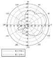
도 2는 도 1의 제1 안테나 및 제2 안테나의 방사 패턴을 설명하기 위한 도면이다.
도 3은 본 발명에 따른 무인항공기 추적 안테나를 이용하는 통신 장치의 구성을 설명하기 위한 도면이다.
도 4는 도 3의 수신부의 세부 구성을 설명하기 위한 도면이다.
도 5는 본 발명에 따른 무인항공기 추적 안테나를 이용하는 통신 방법의 구성을 설명하기 위한 도면이다.1 is a view for explaining the structure of an unmanned aerial vehicle tracking antenna according to the present invention.
FIG. 2 is a view for explaining a radiation pattern of the first antenna and the second antenna of FIG. 1;
3 is a diagram for explaining a configuration of a communication apparatus using an unmanned aerial tracking antenna according to the present invention.
4 is a diagram for explaining the detailed configuration of the receiving unit of FIG.
5 is a diagram for explaining a configuration of a communication method using an unmanned aerial tracking antenna according to the present invention.
이하, 본 발명이 속하는 기술분야에서 통상의 지식을 가진 자가 본 발명의 기술적 사상을 용이하게 실시할 수 있을 정도로 상세히 설명하기 위하여, 본 발명의 가장 바람직한 실시예를 첨부 도면을 참조하여 설명하기로 한다. 우선, 각 도면의 구성요소들에 참조부호를 부가함에 있어서, 동일한 구성요소들에 대해서는 비록 다른 도면상에 표시되더라도 가능한 한 동일한 부호를 가지도록 하고 있음에 유의해야 한다. 또한, 본 발명을 설명함에 있어, 관련된 공지 구성 또는 기능에 대한 구체적인 설명이 본 발명의 요지를 흐릴 수 있다고 판단되는 경우에는 그 상세한 설명은 생략한다.
DETAILED DESCRIPTION OF THE PREFERRED EMBODIMENTS Hereinafter, preferred embodiments of the present invention will be described in detail with reference to the accompanying drawings in order to facilitate a person skilled in the art to easily carry out the technical idea of the present invention. . First, in adding reference numerals to the constituent elements of the drawings, it is to be noted that the same constituent elements are denoted by the same reference symbols as possible even if they are shown in different drawings. In the following description of the present invention, a detailed description of known functions and configurations incorporated herein will be omitted when it may make the subject matter of the present invention rather unclear.
이하에서는, 본 발명의 실시예에 따른 무인항공기 추적 안테나, 이를 이용하는 통신 장치 및 방법에 대하여 첨부한 도면을 참고로 하여 상세히 설명한다.
Hereinafter, an unmanned aerial vehicle tracking antenna according to an embodiment of the present invention, a communication apparatus and a method using the same will be described in detail with reference to the accompanying drawings.
도 1은 본 발명에 따른 무인항공기 추적 안테나의 구조를 설명하기 위한 도면이고, 도 2는 도 1의 제1 안테나 및 제2 안테나의 방사 패턴을 설명하기 위한 도면이다.FIG. 1 is a view for explaining a structure of an unmanned aerial vehicle tracking antenna according to the present invention, and FIG. 2 is a view for explaining a radiation pattern of the first antenna and the second antenna of FIG.
도 1을 참조하여 설명하면, 본 발명에 따른 무인항공기 추적 안테나(100)는 받침부(101), 회전축(102), 방위각 조정부(103), 제1 안테나(110) 및 제2 안테나(120)를 포함한다.1, the
받침부(101)는 바닥에 제1 안테나(110) 및 제2 안테나(120)를 고정한다.The
회전축(102)은 받침부(101)의 상단에 고정되어 제1 안테나(110) 및 제2 안테나(120)를 지지한다.The rotating
방위각 조정부(103)는 받침부(101)와 제1 안테나(110) 및 제2 안테나(120) 사이에 설치하되, 받침부(101)에 대하여 회전축이 회전가능하도록 설치되어, 받침부를 중심으로 무인 항공기의 위치에 따라 모터와 같은 전동 수단을 이용하여 제1 안테나(110) 및 제2 안테나(120)의 방위각을 조정한다. 이때, 방위각 조정부(103)는 무인 항공기의 위치를 인식하는 위치 인식 수단(도면 미도시)을 더 구비할 수 있다.The
제1 안테나(110)는 제1 고각을 형성하며 회전축에 결합된다. 제1 고각은 15°내지 20°각으로 형성되는 것이 바람직하며 본 발명에서는 약 17°각으로 형성되었다. 그리고 제1 안테나(110)는 배열 안테나로 이루어질 수 있다.The
제2 안테나(120)는 제1 안테나 상부에 구비되되, 제2 고각을 형성하며 회전축에 결합된다. 이때, 제2 안테나(120)는 제1 안테나와 동일한 회전축에 결합된다. 제2 고각은 55°내지 65°각으로 형성되는 것이 바람직하며 본 발명에서나는 약 60°각으로 형성되었다, 그리고 제2 안테나(120)는 패치 안테나로 이루어질 수 있다.The
이와 같이 구성된 제1 안테나(110) 및 제2 안테나(120)는 도 2에 도시된 바와 같이, 제2 안테나(120)의 방사 패턴 이득이 수직 방향과 널 포인트 지점에서 더 높은 것을 확인할 수 있다. 따라서, 제2 안테나(120)는 수직방향 상공과 널포인트의 지점과의 근거리 통신을 담당하며 제1 안테나(110)는 원거리 통신을 담당한다.
As shown in FIG. 2, the
도 3은 본 발명에 따른 무인항공기 추적 안테나를 이용하는 통신 장치의 구성을 설명하기 위한 도면이고, 도 4는 도 3의 수신부의 세부 구성을 설명하기 위한 도면이다.FIG. 3 is a view for explaining a configuration of a communication apparatus using an unmanned aerial tracking antenna according to the present invention, and FIG. 4 is a diagram for explaining a detailed configuration of a receiving unit in FIG.
도 3을 참조하여 설명하면, 본 발명에 따른 무인항공기 추적 안테나를 이용하는 통신 장치(200)는 앞서 설명한 무인항공기 추적 안테나(100)를 이용하는 것으로, 이하 중복되는 설명은 생략하기로 한다.Referring to FIG. 3, the
제1 수신부(210)는 제1 안테나(110)에 구비되어, 무인 항공기로부터 전파를 수신받는다. 이때, 제1 안테나(110)는 제1 고각을 형성하며 회전축에 결합되는 원거리용 배열 안테나로 이루어질 수 있다.The first receiving
제2 수신부(220)는 제2 안테나(120)에 구비되어, 무인 항공기로부터 전파를 수신받는다. 이때, 제2 안테나(120)는 제1 안테나(110) 상부에 제2 고각을 형성하며 회전축에 결합되는 근거리용 패치 안테나로 이루어질 수 있다The second receiving unit 220 is provided in the
제어부(230)는 제1 수신부(210) 및 제2 수신부(220)가 수신한 전파를 입력받아 신호 세기를 측정하고 비교하여, 지상 통제 장치(240)로 전송되는 전파를 제어한다.The
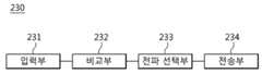
이를 위해, 제어부(230)는 도 4에 도시된 바와 같이 입력부(231), 비교부(232), 전파 선택부(233) 및 전송부(234)를 포함한다.4, the
입력부(231)는 제1 수신부(210) 및 제2 수신부(220)가 수신한 전파를 입력받는다.The
비교부(232)는 입력된 전파의 신호 세기를 측정하여 비교한다.The comparing
전파 선택부(233)는 비교 결과, 높은 신호 세기에 해당하는 전파를 선택한다.The radio
전송부(234)는 선택된 전파를 지상 통제 장치(240)에 전송한다.
The transmitting
도 5는 본 발명에 따른 무인항공기 추적 안테나를 이용하는 통신 방법의 구성을 설명하기 위한 도면이다.5 is a diagram for explaining a configuration of a communication method using an unmanned aerial tracking antenna according to the present invention.
도 5를 참조하여 설명하면, 본 발명에 따른 무인항공기 추적 안테나를 이용하는 통신 방법은 앞서 설명한 바와 같은 무인항공기 추적 안테나를 이용하는 통신 장치를 이용하는 것으로, 이하 중복되는 설명은 생략하기로 한다.Referring to FIG. 5, the communication method using the unmanned airplane tracking antenna according to the present invention uses a communication device using the unmanned airplane tracking antenna as described above, and a repeated description will be omitted.
먼저, 제1 안테나에 구비되는 제1 수신부에 의해, 무인 항공기로부터 전파를 수신받는다.(S100)First, a radio wave is received from the unmanned airplane by a first receiving unit provided in the first antenna (S100)
다음, 제1 안테나와 동일한 회전축에 결합되는 제2 안테나에 구비되는 제2 수신부에 의해, 무인 항공기로부터 전파를 수신받는다.(S200)Next, a radio wave is received from the unmanned airplane by a second receiving unit included in a second antenna coupled to the same axis as the first antenna (S200).
다음. 제1 수신부 및 상기 제2 수신부가 수신한 전파를 입력받아 신호 세기를 측정하고 비교한다.(S300)next. The first receiving unit and the second receiving unit receive the received radio waves and measure and compare the signal strengths.
다음, 비교 결과, 높은 신호 세기에 해당하는 전파를 선택한다.(S400)Next, as a comparison result, a radio wave corresponding to a high signal strength is selected (S400)
다음, 선택된 전파를 지상 통제 장치에 전송한다.(S500)
Next, the selected radio wave is transmitted to the ground control device (S500)
이처럼, 본 발명에 의한 무인항공기 추적 안테나, 이를 이용하는 통신 장치 및 방법는 평판형 배열 안테나와 패치 안테나를 조합하여 원거리에서는 평판형 배열 안테나를 통해 통신하고, 근거리에서는 패치 안테나를 통해 통신함으로써, 무인항공기와의 통신 성능을 극대화할 수 있다.As described above, the unmanned airplane tracking antenna according to the present invention, a communication apparatus and a method using the same, communicate with each other through a plate-type array antenna at a long distance and through a patch antenna at a short distance by combining a planar array antenna and a patch antenna, Thereby maximizing the communication performance of the mobile communication terminal.
또한, 본 발명은 방위각을 조절하기 위해 하나의 모터만을 사용하여 안테나의 소형화와 경량화를 구현할 수 있다.
In addition, the present invention can reduce the size and weight of the antenna by using only one motor to adjust the azimuth angle.
이상에서, 본 발명에 따른 바람직한 실시예에 대해 설명하였으나, 다양한 형태로 변형이 가능하며, 본 기술분야에서 통상의 지식을 가진자라면 본 발명의 특허청구범위를 벗어남이 없이 다양한 변형예 및 수정예를 실시할 수 있을 것으로 이해된다.While the present invention has been particularly shown and described with reference to exemplary embodiments thereof, it is evident that many alternatives, modifications, and variations will be apparent to those skilled in the art without departing from the scope of the appended claims. As will be understood by those skilled in the art.
100 : 무인항공기 추적 안테나
110 : 제1 안테나 120 : 제2 안테나
200 : 무인항공기 추적 안테나 통신 장치
210 : 제1 수신부 220 : 제2 수신부
230 : 제어부100: Unmanned Aircraft Tracking Antenna
110: first antenna 120: second antenna
200: Unmanned Aircraft Tracking Antenna Communication Device
210: first receiving unit 220: second receiving unit
230:
Claims (14)
Translated fromKorean상기 제1 안테나의 상부에 구비되는 제2 안테나;
상기 제1 안테나 및 상기 제2 안테나를 바닥에 고정하는 받침부;
상기 받침부의 상단에 고정되어 상기 제1 안테나 및 상기 제2 안테나를 지지하는 회전축; 및
상기 받침부와 상기 제1 안테나 및 상기 제2 안테나 사이에 설치하되, 상기 받침부에 대하여 상기 회전축이 회전가능하도록 설치되어, 상기 받침부를 중심으로 무인 항공기의 위치에 따라 상기 제1 안테나 및 상기 제2 안테나의 방위각을 조정하는 방위각 조정부;를 포함하고,
상기 제1 안테나는 15°내지 20°각을 형성하는 제1 고각을 형성하여 상기 회전축에 결합되고,
상기 제2 안테나는 55°내지 65°각을 형성하는 제2 고각을 형성하여 상기 회전축에 결합되고,
상기 제1 고각은 제1 안테나의 방사패턴이득이 가장 높은 지점에 상응되며,
상기 제2 고각은 제1 안테나의 널 포인트 지점에 상응되는
것을 특징으로 하는 무인항공기 추적 안테나.A first antenna;
A second antenna provided on the first antenna;
A pedestal for fixing the first antenna and the second antenna to the floor;
A rotating shaft fixed to an upper end of the receiving unit to support the first antenna and the second antenna; And
The first antenna and the second antenna are installed between the receiving unit and the first antenna and the second antenna so that the rotating shaft is rotatable with respect to the receiving unit, And an azimuth angle adjusting unit for adjusting azimuth angles of the two antennas,
Wherein the first antenna is coupled to the rotation axis by forming a first elevation angle that forms an angle of 15 to 20,
Wherein the second antenna is coupled to the rotating shaft by forming a second elevation angle that forms an angle of between 55 and 65,
Wherein the first elevation angle corresponds to a point at which the radiation pattern gain of the first antenna is highest,
The second elevation angle corresponds to a null point of the first antenna
Wherein said tracking antenna comprises:
상기 제1 안테나는 배열 안테나인 것을 특징으로 하는 무인항공기 추적 안테나.The method according to claim 1,
Wherein the first antenna is an array antenna.
상기 제2 안테나는 패치 안테나인 것을 특징으로 하는 무인항공기 추적 안테나.The method according to claim 1,
Wherein the second antenna is a patch antenna.
상기 방위각 조정부은 무인 항공기의 위치를 인식하는 위치 인식 수단을 구비하는 것을 특징으로 하는 무인항공기 추적 안테나.The method according to claim 1,
Wherein the azimuth angle adjusting unit includes a position recognizing unit that recognizes a position of the UAV.
상기 제1 안테나와 동일한 회전축에 결합되는 제2 안테나에 구비되어, 상기 무인 항공기로부터 전파를 수신받는 제2 수신부; 및
상기 제1 수신부 및 상기 제2 수신부가 수신한 전파를 입력받아 신호 세기를 측정하고 비교하여, 지상 통제 장치로 전송되는 전파를 제어하는 제어부;
를 포함하는고,
상기 제1 안테나는 15°내지 20°각을 형성하는 제1 고각을 형성하여 상기 회전축에 결합되고,
상기 제2 안테나는 55°내지 65°각을 형성하는 제2 고각을 형성하여 상기 회전축에 결합되고,
상기 제1 고각은 제1 안테나의 방사패턴이득이 가장 높은 지점에 상응되며,
상기 제2 고각은 제1 안테나의 널 포인트 지점에 상응되는
것을 특징으로 하는 무인항공기 추적 안테나를 이용한 통신 장치.A first receiving unit provided in the first antenna and receiving a radio wave from the unmanned airplane;
A second receiving unit provided in a second antenna coupled to the same axis as the first antenna, the second receiving unit receiving a radio wave from the unmanned air vehicle; And
A controller receiving a radio wave received by the first receiver and the second receiver to measure and compare signal intensities and to control a radio wave transmitted to the ground control device;
, ≪ / RTI >
Wherein the first antenna is coupled to the rotation axis by forming a first elevation angle that forms an angle of 15 to 20,
Wherein the second antenna is coupled to the rotating shaft by forming a second elevation angle that forms an angle of between 55 and 65,
Wherein the first elevation angle corresponds to a point at which the radiation pattern gain of the first antenna is highest,
The second elevation angle corresponds to a null point of the first antenna
Wherein the antenna is used as a tracking antenna.
상기 제어부는,
상기 제1 수신부 및 상기 제2 수신부가 수신한 전파를 입력받는 입력부;
입력된 전파의 신호 세기를 측정하여 비교하는 비교부;
비교 결과, 높은 신호 세기에 해당하는 전파를 선택하는 전파 선택부; 및
선택된 전파를 상기 지상 통제 장치에 전송하는 전송부;
를 포함하는 것을 특징으로 하는 무인항공기 추적 안테나를 이용한 통신 장치.10. The method of claim 9,
Wherein,
An input unit for receiving a radio wave received by the first receiver and the second receiver;
A comparison unit for measuring and comparing the intensity of the input radio wave;
As a result of comparison, a radio wave selecting unit for selecting a radio wave corresponding to a high signal strength; And
A transmitting unit for transmitting the selected radio wave to the ground control device;
And a controller for controlling the antenna.
상기 제1 안테나는 원거리용 배열 안테나인 것을 특징으로 하는 무인항공기 추적 안테나를 이용한 통신 장치.10. The method of claim 9,
Wherein the first antenna is an array antenna for a long distance.
상기 제2 안테나는 근거리용 패치 안테나인 것을 특징으로 하는 무인항공기 추적 안테나를 이용한 통신 장치.10. The method of claim 9,
Wherein the second antenna is a near-field patch antenna.
상기 제1 안테나와 동일한 회전축에 결합되는 제2 안테나에 구비되는 제2 수신부에 의해, 상기 무인 항공기로부터 전파를 수신받는 단계; 및
제어부에 의해, 상기 제1 수신부 및 상기 제2 수신부가 수신한 전파를 입력받아 신호 세기를 측정하고 비교하여, 지상 통제 장치로 전송되는 전파를 제어하는 단계;
를 포함하고,
상기 제1 안테나는 15°내지 20°각을 형성하는 제1 고각을 형성하여 상기 회전축에 결합되고,
상기 제2 안테나는 55°내지 65°각을 형성하는 제2 고각을 형성하여 상기 회전축에 결합되고,
상기 제1 고각은 제1 안테나의 방사패턴이득이 가장 높은 지점에 상응되며,
상기 제2 고각은 제1 안테나의 널 포인트 지점에 상응되는
것을 특징으로 하는 무인항공기 추적 안테나를 이용한 통신 방법.Receiving a radio wave from an unmanned airplane by a first receiving unit included in the first antenna;
Receiving a radio wave from the unmanned airplane by a second receiving unit included in a second antenna coupled to the same axis as the first antenna; And
Controlling a radio wave transmitted to the terrestrial control apparatus by measuring and comparing signal intensities by receiving a radio wave received by the first receiving unit and the second receiving unit by a control unit;
Lt; / RTI >
Wherein the first antenna is coupled to the rotation axis by forming a first elevation angle that forms an angle of 15 to 20,
Wherein the second antenna is coupled to the rotating shaft by forming a second elevation angle that forms an angle of between 55 and 65,
Wherein the first elevation angle corresponds to a point at which the radiation pattern gain of the first antenna is highest,
The second elevation angle corresponds to a null point of the first antenna
Wherein the tracking antenna comprises a first antenna and a second antenna.
상기 제1 수신부 및 상기 제2 수신부가 수신한 전파를 입력받아 신호 세기를 측정하고 비교하여, 지상 통제 장치로 전송되는 전파를 제어하는 단계는,
상기 제1 수신부 및 상기 제2 수신부가 수신한 전파를 입력받는 단계;
입력된 전파의 신호 세기를 측정하여 비교하는 단계;
비교 결과, 높은 신호 세기에 해당하는 전파를 선택하는 단계; 및
선택된 전파를 상기 지상 통제 장치에 전송하는 단계;
를 포함하는 것을 특징으로 하는 무인항공기 추적 안테나를 이용한 통신 방법.
14. The method of claim 13,
Wherein the step of receiving the radio waves received by the first receiving unit and the second receiving unit to measure and compare signal intensities and to control the radio waves transmitted to the terrestrial control unit,
Receiving a radio wave received by the first receiver and the second receiver;
Measuring and comparing the intensity of the input radio wave;
Selecting a radio wave corresponding to a high signal strength; And
Transmitting the selected radio wave to the ground control device;
And transmitting the signal to the unmanned aircraft tracking antenna.
Priority Applications (1)
| Application Number | Priority Date | Filing Date | Title |
|---|---|---|---|
| KR1020140006846AKR101553710B1 (en) | 2014-01-20 | 2014-01-20 | Uav tracking antenna, communication apparatus and method that uses it |
Applications Claiming Priority (1)
| Application Number | Priority Date | Filing Date | Title |
|---|---|---|---|
| KR1020140006846AKR101553710B1 (en) | 2014-01-20 | 2014-01-20 | Uav tracking antenna, communication apparatus and method that uses it |
Publications (2)
| Publication Number | Publication Date |
|---|---|
| KR20150087455A KR20150087455A (en) | 2015-07-30 |
| KR101553710B1true KR101553710B1 (en) | 2015-09-17 |
Family
ID=53876657
Family Applications (1)
| Application Number | Title | Priority Date | Filing Date |
|---|---|---|---|
| KR1020140006846AActiveKR101553710B1 (en) | 2014-01-20 | 2014-01-20 | Uav tracking antenna, communication apparatus and method that uses it |
Country Status (1)
| Country | Link |
|---|---|
| KR (1) | KR101553710B1 (en) |
Cited By (1)
| Publication number | Priority date | Publication date | Assignee | Title |
|---|---|---|---|---|
| KR102598880B1 (en) | 2022-11-16 | 2023-11-06 | 한화시스템 주식회사 | Inspection apparatus and method for uas(unmanned aircraft systems) ground antenna |
Families Citing this family (155)
| Publication number | Priority date | Publication date | Assignee | Title |
|---|---|---|---|---|
| US9113347B2 (en) | 2012-12-05 | 2015-08-18 | At&T Intellectual Property I, Lp | Backhaul link for distributed antenna system |
| US10009065B2 (en) | 2012-12-05 | 2018-06-26 | At&T Intellectual Property I, L.P. | Backhaul link for distributed antenna system |
| US9999038B2 (en) | 2013-05-31 | 2018-06-12 | At&T Intellectual Property I, L.P. | Remote distributed antenna system |
| US9525524B2 (en) | 2013-05-31 | 2016-12-20 | At&T Intellectual Property I, L.P. | Remote distributed antenna system |
| US8897697B1 (en) | 2013-11-06 | 2014-11-25 | At&T Intellectual Property I, Lp | Millimeter-wave surface-wave communications |
| US9209902B2 (en) | 2013-12-10 | 2015-12-08 | At&T Intellectual Property I, L.P. | Quasi-optical coupler |
| US9692101B2 (en) | 2014-08-26 | 2017-06-27 | At&T Intellectual Property I, L.P. | Guided wave couplers for coupling electromagnetic waves between a waveguide surface and a surface of a wire |
| US9768833B2 (en) | 2014-09-15 | 2017-09-19 | At&T Intellectual Property I, L.P. | Method and apparatus for sensing a condition in a transmission medium of electromagnetic waves |
| US10063280B2 (en) | 2014-09-17 | 2018-08-28 | At&T Intellectual Property I, L.P. | Monitoring and mitigating conditions in a communication network |
| US9615269B2 (en) | 2014-10-02 | 2017-04-04 | At&T Intellectual Property I, L.P. | Method and apparatus that provides fault tolerance in a communication network |
| US9685992B2 (en) | 2014-10-03 | 2017-06-20 | At&T Intellectual Property I, L.P. | Circuit panel network and methods thereof |
| US9503189B2 (en) | 2014-10-10 | 2016-11-22 | At&T Intellectual Property I, L.P. | Method and apparatus for arranging communication sessions in a communication system |
| US9973299B2 (en) | 2014-10-14 | 2018-05-15 | At&T Intellectual Property I, L.P. | Method and apparatus for adjusting a mode of communication in a communication network |
| US9762289B2 (en) | 2014-10-14 | 2017-09-12 | At&T Intellectual Property I, L.P. | Method and apparatus for transmitting or receiving signals in a transportation system |
| US9312919B1 (en) | 2014-10-21 | 2016-04-12 | At&T Intellectual Property I, Lp | Transmission device with impairment compensation and methods for use therewith |
| US9577306B2 (en) | 2014-10-21 | 2017-02-21 | At&T Intellectual Property I, L.P. | Guided-wave transmission device and methods for use therewith |
| US9780834B2 (en) | 2014-10-21 | 2017-10-03 | At&T Intellectual Property I, L.P. | Method and apparatus for transmitting electromagnetic waves |
| US9653770B2 (en) | 2014-10-21 | 2017-05-16 | At&T Intellectual Property I, L.P. | Guided wave coupler, coupling module and methods for use therewith |
| US9520945B2 (en) | 2014-10-21 | 2016-12-13 | At&T Intellectual Property I, L.P. | Apparatus for providing communication services and methods thereof |
| US9769020B2 (en) | 2014-10-21 | 2017-09-19 | At&T Intellectual Property I, L.P. | Method and apparatus for responding to events affecting communications in a communication network |
| US9627768B2 (en) | 2014-10-21 | 2017-04-18 | At&T Intellectual Property I, L.P. | Guided-wave transmission device with non-fundamental mode propagation and methods for use therewith |
| US10243784B2 (en) | 2014-11-20 | 2019-03-26 | At&T Intellectual Property I, L.P. | System for generating topology information and methods thereof |
| US9954287B2 (en) | 2014-11-20 | 2018-04-24 | At&T Intellectual Property I, L.P. | Apparatus for converting wireless signals and electromagnetic waves and methods thereof |
| US9544006B2 (en) | 2014-11-20 | 2017-01-10 | At&T Intellectual Property I, L.P. | Transmission device with mode division multiplexing and methods for use therewith |
| US10009067B2 (en) | 2014-12-04 | 2018-06-26 | At&T Intellectual Property I, L.P. | Method and apparatus for configuring a communication interface |
| US9461706B1 (en) | 2015-07-31 | 2016-10-04 | At&T Intellectual Property I, Lp | Method and apparatus for exchanging communication signals |
| US9680670B2 (en) | 2014-11-20 | 2017-06-13 | At&T Intellectual Property I, L.P. | Transmission device with channel equalization and control and methods for use therewith |
| US9800327B2 (en) | 2014-11-20 | 2017-10-24 | At&T Intellectual Property I, L.P. | Apparatus for controlling operations of a communication device and methods thereof |
| US10340573B2 (en) | 2016-10-26 | 2019-07-02 | At&T Intellectual Property I, L.P. | Launcher with cylindrical coupling device and methods for use therewith |
| US9742462B2 (en) | 2014-12-04 | 2017-08-22 | At&T Intellectual Property I, L.P. | Transmission medium and communication interfaces and methods for use therewith |
| US9654173B2 (en) | 2014-11-20 | 2017-05-16 | At&T Intellectual Property I, L.P. | Apparatus for powering a communication device and methods thereof |
| US9997819B2 (en) | 2015-06-09 | 2018-06-12 | At&T Intellectual Property I, L.P. | Transmission medium and method for facilitating propagation of electromagnetic waves via a core |
| US10144036B2 (en) | 2015-01-30 | 2018-12-04 | At&T Intellectual Property I, L.P. | Method and apparatus for mitigating interference affecting a propagation of electromagnetic waves guided by a transmission medium |
| US9876570B2 (en) | 2015-02-20 | 2018-01-23 | At&T Intellectual Property I, Lp | Guided-wave transmission device with non-fundamental mode propagation and methods for use therewith |
| US9749013B2 (en) | 2015-03-17 | 2017-08-29 | At&T Intellectual Property I, L.P. | Method and apparatus for reducing attenuation of electromagnetic waves guided by a transmission medium |
| US9705561B2 (en) | 2015-04-24 | 2017-07-11 | At&T Intellectual Property I, L.P. | Directional coupling device and methods for use therewith |
| US10224981B2 (en) | 2015-04-24 | 2019-03-05 | At&T Intellectual Property I, Lp | Passive electrical coupling device and methods for use therewith |
| US9793954B2 (en) | 2015-04-28 | 2017-10-17 | At&T Intellectual Property I, L.P. | Magnetic coupling device and methods for use therewith |
| US9948354B2 (en) | 2015-04-28 | 2018-04-17 | At&T Intellectual Property I, L.P. | Magnetic coupling device with reflective plate and methods for use therewith |
| US9490869B1 (en) | 2015-05-14 | 2016-11-08 | At&T Intellectual Property I, L.P. | Transmission medium having multiple cores and methods for use therewith |
| US9748626B2 (en) | 2015-05-14 | 2017-08-29 | At&T Intellectual Property I, L.P. | Plurality of cables having different cross-sectional shapes which are bundled together to form a transmission medium |
| US9871282B2 (en) | 2015-05-14 | 2018-01-16 | At&T Intellectual Property I, L.P. | At least one transmission medium having a dielectric surface that is covered at least in part by a second dielectric |
| US10650940B2 (en) | 2015-05-15 | 2020-05-12 | At&T Intellectual Property I, L.P. | Transmission medium having a conductive material and methods for use therewith |
| US9917341B2 (en) | 2015-05-27 | 2018-03-13 | At&T Intellectual Property I, L.P. | Apparatus and method for launching electromagnetic waves and for modifying radial dimensions of the propagating electromagnetic waves |
| US10812174B2 (en) | 2015-06-03 | 2020-10-20 | At&T Intellectual Property I, L.P. | Client node device and methods for use therewith |
| US9912381B2 (en) | 2015-06-03 | 2018-03-06 | At&T Intellectual Property I, Lp | Network termination and methods for use therewith |
| US9866309B2 (en) | 2015-06-03 | 2018-01-09 | At&T Intellectual Property I, Lp | Host node device and methods for use therewith |
| US10103801B2 (en) | 2015-06-03 | 2018-10-16 | At&T Intellectual Property I, L.P. | Host node device and methods for use therewith |
| US9913139B2 (en) | 2015-06-09 | 2018-03-06 | At&T Intellectual Property I, L.P. | Signal fingerprinting for authentication of communicating devices |
| US10142086B2 (en) | 2015-06-11 | 2018-11-27 | At&T Intellectual Property I, L.P. | Repeater and methods for use therewith |
| US9608692B2 (en) | 2015-06-11 | 2017-03-28 | At&T Intellectual Property I, L.P. | Repeater and methods for use therewith |
| US9820146B2 (en) | 2015-06-12 | 2017-11-14 | At&T Intellectual Property I, L.P. | Method and apparatus for authentication and identity management of communicating devices |
| US9667317B2 (en) | 2015-06-15 | 2017-05-30 | At&T Intellectual Property I, L.P. | Method and apparatus for providing security using network traffic adjustments |
| US9509415B1 (en) | 2015-06-25 | 2016-11-29 | At&T Intellectual Property I, L.P. | Methods and apparatus for inducing a fundamental wave mode on a transmission medium |
| US9640850B2 (en) | 2015-06-25 | 2017-05-02 | At&T Intellectual Property I, L.P. | Methods and apparatus for inducing a non-fundamental wave mode on a transmission medium |
| US9865911B2 (en) | 2015-06-25 | 2018-01-09 | At&T Intellectual Property I, L.P. | Waveguide system for slot radiating first electromagnetic waves that are combined into a non-fundamental wave mode second electromagnetic wave on a transmission medium |
| US9853342B2 (en) | 2015-07-14 | 2017-12-26 | At&T Intellectual Property I, L.P. | Dielectric transmission medium connector and methods for use therewith |
| US9847566B2 (en) | 2015-07-14 | 2017-12-19 | At&T Intellectual Property I, L.P. | Method and apparatus for adjusting a field of a signal to mitigate interference |
| US10033108B2 (en) | 2015-07-14 | 2018-07-24 | At&T Intellectual Property I, L.P. | Apparatus and methods for generating an electromagnetic wave having a wave mode that mitigates interference |
| US9882257B2 (en) | 2015-07-14 | 2018-01-30 | At&T Intellectual Property I, L.P. | Method and apparatus for launching a wave mode that mitigates interference |
| US10148016B2 (en) | 2015-07-14 | 2018-12-04 | At&T Intellectual Property I, L.P. | Apparatus and methods for communicating utilizing an antenna array |
| US10033107B2 (en) | 2015-07-14 | 2018-07-24 | At&T Intellectual Property I, L.P. | Method and apparatus for coupling an antenna to a device |
| US9836957B2 (en) | 2015-07-14 | 2017-12-05 | At&T Intellectual Property I, L.P. | Method and apparatus for communicating with premises equipment |
| US10170840B2 (en) | 2015-07-14 | 2019-01-01 | At&T Intellectual Property I, L.P. | Apparatus and methods for sending or receiving electromagnetic signals |
| US10205655B2 (en) | 2015-07-14 | 2019-02-12 | At&T Intellectual Property I, L.P. | Apparatus and methods for communicating utilizing an antenna array and multiple communication paths |
| US10044409B2 (en) | 2015-07-14 | 2018-08-07 | At&T Intellectual Property I, L.P. | Transmission medium and methods for use therewith |
| US10341142B2 (en) | 2015-07-14 | 2019-07-02 | At&T Intellectual Property I, L.P. | Apparatus and methods for generating non-interfering electromagnetic waves on an uninsulated conductor |
| US10320586B2 (en) | 2015-07-14 | 2019-06-11 | At&T Intellectual Property I, L.P. | Apparatus and methods for generating non-interfering electromagnetic waves on an insulated transmission medium |
| US9722318B2 (en) | 2015-07-14 | 2017-08-01 | At&T Intellectual Property I, L.P. | Method and apparatus for coupling an antenna to a device |
| US9628116B2 (en) | 2015-07-14 | 2017-04-18 | At&T Intellectual Property I, L.P. | Apparatus and methods for transmitting wireless signals |
| US9608740B2 (en) | 2015-07-15 | 2017-03-28 | At&T Intellectual Property I, L.P. | Method and apparatus for launching a wave mode that mitigates interference |
| US10090606B2 (en) | 2015-07-15 | 2018-10-02 | At&T Intellectual Property I, L.P. | Antenna system with dielectric array and methods for use therewith |
| US9793951B2 (en) | 2015-07-15 | 2017-10-17 | At&T Intellectual Property I, L.P. | Method and apparatus for launching a wave mode that mitigates interference |
| US9948333B2 (en) | 2015-07-23 | 2018-04-17 | At&T Intellectual Property I, L.P. | Method and apparatus for wireless communications to mitigate interference |
| US9871283B2 (en) | 2015-07-23 | 2018-01-16 | At&T Intellectual Property I, Lp | Transmission medium having a dielectric core comprised of plural members connected by a ball and socket configuration |
| US9912027B2 (en) | 2015-07-23 | 2018-03-06 | At&T Intellectual Property I, L.P. | Method and apparatus for exchanging communication signals |
| US10784670B2 (en) | 2015-07-23 | 2020-09-22 | At&T Intellectual Property I, L.P. | Antenna support for aligning an antenna |
| US9749053B2 (en) | 2015-07-23 | 2017-08-29 | At&T Intellectual Property I, L.P. | Node device, repeater and methods for use therewith |
| US10020587B2 (en) | 2015-07-31 | 2018-07-10 | At&T Intellectual Property I, L.P. | Radial antenna and methods for use therewith |
| US9967173B2 (en) | 2015-07-31 | 2018-05-08 | At&T Intellectual Property I, L.P. | Method and apparatus for authentication and identity management of communicating devices |
| US9735833B2 (en) | 2015-07-31 | 2017-08-15 | At&T Intellectual Property I, L.P. | Method and apparatus for communications management in a neighborhood network |
| US9904535B2 (en) | 2015-09-14 | 2018-02-27 | At&T Intellectual Property I, L.P. | Method and apparatus for distributing software |
| US10009901B2 (en) | 2015-09-16 | 2018-06-26 | At&T Intellectual Property I, L.P. | Method, apparatus, and computer-readable storage medium for managing utilization of wireless resources between base stations |
| US10136434B2 (en) | 2015-09-16 | 2018-11-20 | At&T Intellectual Property I, L.P. | Method and apparatus for use with a radio distributed antenna system having an ultra-wideband control channel |
| US10079661B2 (en) | 2015-09-16 | 2018-09-18 | At&T Intellectual Property I, L.P. | Method and apparatus for use with a radio distributed antenna system having a clock reference |
| US10009063B2 (en) | 2015-09-16 | 2018-06-26 | At&T Intellectual Property I, L.P. | Method and apparatus for use with a radio distributed antenna system having an out-of-band reference signal |
| US9769128B2 (en) | 2015-09-28 | 2017-09-19 | At&T Intellectual Property I, L.P. | Method and apparatus for encryption of communications over a network |
| US9729197B2 (en) | 2015-10-01 | 2017-08-08 | At&T Intellectual Property I, L.P. | Method and apparatus for communicating network management traffic over a network |
| US9882277B2 (en) | 2015-10-02 | 2018-01-30 | At&T Intellectual Property I, Lp | Communication device and antenna assembly with actuated gimbal mount |
| US9876264B2 (en) | 2015-10-02 | 2018-01-23 | At&T Intellectual Property I, Lp | Communication system, guided wave switch and methods for use therewith |
| US10355367B2 (en) | 2015-10-16 | 2019-07-16 | At&T Intellectual Property I, L.P. | Antenna structure for exchanging wireless signals |
| US10665942B2 (en) | 2015-10-16 | 2020-05-26 | At&T Intellectual Property I, L.P. | Method and apparatus for adjusting wireless communications |
| US9912419B1 (en) | 2016-08-24 | 2018-03-06 | At&T Intellectual Property I, L.P. | Method and apparatus for managing a fault in a distributed antenna system |
| US9860075B1 (en) | 2016-08-26 | 2018-01-02 | At&T Intellectual Property I, L.P. | Method and communication node for broadband distribution |
| US10291311B2 (en) | 2016-09-09 | 2019-05-14 | At&T Intellectual Property I, L.P. | Method and apparatus for mitigating a fault in a distributed antenna system |
| US11032819B2 (en) | 2016-09-15 | 2021-06-08 | At&T Intellectual Property I, L.P. | Method and apparatus for use with a radio distributed antenna system having a control channel reference signal |
| US10135146B2 (en) | 2016-10-18 | 2018-11-20 | At&T Intellectual Property I, L.P. | Apparatus and methods for launching guided waves via circuits |
| US10340600B2 (en) | 2016-10-18 | 2019-07-02 | At&T Intellectual Property I, L.P. | Apparatus and methods for launching guided waves via plural waveguide systems |
| US10135147B2 (en) | 2016-10-18 | 2018-11-20 | At&T Intellectual Property I, L.P. | Apparatus and methods for launching guided waves via an antenna |
| US9876605B1 (en) | 2016-10-21 | 2018-01-23 | At&T Intellectual Property I, L.P. | Launcher and coupling system to support desired guided wave mode |
| US9991580B2 (en) | 2016-10-21 | 2018-06-05 | At&T Intellectual Property I, L.P. | Launcher and coupling system for guided wave mode cancellation |
| US10811767B2 (en) | 2016-10-21 | 2020-10-20 | At&T Intellectual Property I, L.P. | System and dielectric antenna with convex dielectric radome |
| US10374316B2 (en) | 2016-10-21 | 2019-08-06 | At&T Intellectual Property I, L.P. | System and dielectric antenna with non-uniform dielectric |
| US10312567B2 (en) | 2016-10-26 | 2019-06-04 | At&T Intellectual Property I, L.P. | Launcher with planar strip antenna and methods for use therewith |
| US10224634B2 (en) | 2016-11-03 | 2019-03-05 | At&T Intellectual Property I, L.P. | Methods and apparatus for adjusting an operational characteristic of an antenna |
| US10498044B2 (en) | 2016-11-03 | 2019-12-03 | At&T Intellectual Property I, L.P. | Apparatus for configuring a surface of an antenna |
| US10225025B2 (en) | 2016-11-03 | 2019-03-05 | At&T Intellectual Property I, L.P. | Method and apparatus for detecting a fault in a communication system |
| US10291334B2 (en) | 2016-11-03 | 2019-05-14 | At&T Intellectual Property I, L.P. | System for detecting a fault in a communication system |
| US10178445B2 (en) | 2016-11-23 | 2019-01-08 | At&T Intellectual Property I, L.P. | Methods, devices, and systems for load balancing between a plurality of waveguides |
| US10535928B2 (en) | 2016-11-23 | 2020-01-14 | At&T Intellectual Property I, L.P. | Antenna system and methods for use therewith |
| US10340601B2 (en) | 2016-11-23 | 2019-07-02 | At&T Intellectual Property I, L.P. | Multi-antenna system and methods for use therewith |
| US10340603B2 (en) | 2016-11-23 | 2019-07-02 | At&T Intellectual Property I, L.P. | Antenna system having shielded structural configurations for assembly |
| US10090594B2 (en) | 2016-11-23 | 2018-10-02 | At&T Intellectual Property I, L.P. | Antenna system having structural configurations for assembly |
| US10361489B2 (en) | 2016-12-01 | 2019-07-23 | At&T Intellectual Property I, L.P. | Dielectric dish antenna system and methods for use therewith |
| US10305190B2 (en) | 2016-12-01 | 2019-05-28 | At&T Intellectual Property I, L.P. | Reflecting dielectric antenna system and methods for use therewith |
| US10135145B2 (en) | 2016-12-06 | 2018-11-20 | At&T Intellectual Property I, L.P. | Apparatus and methods for generating an electromagnetic wave along a transmission medium |
| US10637149B2 (en) | 2016-12-06 | 2020-04-28 | At&T Intellectual Property I, L.P. | Injection molded dielectric antenna and methods for use therewith |
| US10694379B2 (en) | 2016-12-06 | 2020-06-23 | At&T Intellectual Property I, L.P. | Waveguide system with device-based authentication and methods for use therewith |
| US10727599B2 (en) | 2016-12-06 | 2020-07-28 | At&T Intellectual Property I, L.P. | Launcher with slot antenna and methods for use therewith |
| US10020844B2 (en) | 2016-12-06 | 2018-07-10 | T&T Intellectual Property I, L.P. | Method and apparatus for broadcast communication via guided waves |
| US10755542B2 (en) | 2016-12-06 | 2020-08-25 | At&T Intellectual Property I, L.P. | Method and apparatus for surveillance via guided wave communication |
| US9927517B1 (en) | 2016-12-06 | 2018-03-27 | At&T Intellectual Property I, L.P. | Apparatus and methods for sensing rainfall |
| US10819035B2 (en) | 2016-12-06 | 2020-10-27 | At&T Intellectual Property I, L.P. | Launcher with helical antenna and methods for use therewith |
| US10326494B2 (en) | 2016-12-06 | 2019-06-18 | At&T Intellectual Property I, L.P. | Apparatus for measurement de-embedding and methods for use therewith |
| US10439675B2 (en) | 2016-12-06 | 2019-10-08 | At&T Intellectual Property I, L.P. | Method and apparatus for repeating guided wave communication signals |
| US10382976B2 (en) | 2016-12-06 | 2019-08-13 | At&T Intellectual Property I, L.P. | Method and apparatus for managing wireless communications based on communication paths and network device positions |
| US10389029B2 (en) | 2016-12-07 | 2019-08-20 | At&T Intellectual Property I, L.P. | Multi-feed dielectric antenna system with core selection and methods for use therewith |
| US10359749B2 (en) | 2016-12-07 | 2019-07-23 | At&T Intellectual Property I, L.P. | Method and apparatus for utilities management via guided wave communication |
| US10139820B2 (en) | 2016-12-07 | 2018-11-27 | At&T Intellectual Property I, L.P. | Method and apparatus for deploying equipment of a communication system |
| US10547348B2 (en) | 2016-12-07 | 2020-01-28 | At&T Intellectual Property I, L.P. | Method and apparatus for switching transmission mediums in a communication system |
| US9893795B1 (en) | 2016-12-07 | 2018-02-13 | At&T Intellectual Property I, Lp | Method and repeater for broadband distribution |
| US10168695B2 (en) | 2016-12-07 | 2019-01-01 | At&T Intellectual Property I, L.P. | Method and apparatus for controlling an unmanned aircraft |
| US10446936B2 (en) | 2016-12-07 | 2019-10-15 | At&T Intellectual Property I, L.P. | Multi-feed dielectric antenna system and methods for use therewith |
| US10027397B2 (en) | 2016-12-07 | 2018-07-17 | At&T Intellectual Property I, L.P. | Distributed antenna system and methods for use therewith |
| US10243270B2 (en) | 2016-12-07 | 2019-03-26 | At&T Intellectual Property I, L.P. | Beam adaptive multi-feed dielectric antenna system and methods for use therewith |
| US10389037B2 (en) | 2016-12-08 | 2019-08-20 | At&T Intellectual Property I, L.P. | Apparatus and methods for selecting sections of an antenna array and use therewith |
| US10069535B2 (en) | 2016-12-08 | 2018-09-04 | At&T Intellectual Property I, L.P. | Apparatus and methods for launching electromagnetic waves having a certain electric field structure |
| US10411356B2 (en) | 2016-12-08 | 2019-09-10 | At&T Intellectual Property I, L.P. | Apparatus and methods for selectively targeting communication devices with an antenna array |
| US10777873B2 (en) | 2016-12-08 | 2020-09-15 | At&T Intellectual Property I, L.P. | Method and apparatus for mounting network devices |
| US10601494B2 (en) | 2016-12-08 | 2020-03-24 | At&T Intellectual Property I, L.P. | Dual-band communication device and method for use therewith |
| US10326689B2 (en) | 2016-12-08 | 2019-06-18 | At&T Intellectual Property I, L.P. | Method and system for providing alternative communication paths |
| US9911020B1 (en) | 2016-12-08 | 2018-03-06 | At&T Intellectual Property I, L.P. | Method and apparatus for tracking via a radio frequency identification device |
| US10938108B2 (en) | 2016-12-08 | 2021-03-02 | At&T Intellectual Property I, L.P. | Frequency selective multi-feed dielectric antenna system and methods for use therewith |
| US10103422B2 (en) | 2016-12-08 | 2018-10-16 | At&T Intellectual Property I, L.P. | Method and apparatus for mounting network devices |
| US10264467B2 (en) | 2016-12-08 | 2019-04-16 | At&T Intellectual Property I, L.P. | Method and apparatus for collecting data associated with wireless communications |
| US10530505B2 (en) | 2016-12-08 | 2020-01-07 | At&T Intellectual Property I, L.P. | Apparatus and methods for launching electromagnetic waves along a transmission medium |
| US9998870B1 (en) | 2016-12-08 | 2018-06-12 | At&T Intellectual Property I, L.P. | Method and apparatus for proximity sensing |
| US10916969B2 (en) | 2016-12-08 | 2021-02-09 | At&T Intellectual Property I, L.P. | Method and apparatus for providing power using an inductive coupling |
| US10264586B2 (en) | 2016-12-09 | 2019-04-16 | At&T Mobility Ii Llc | Cloud-based packet controller and methods for use therewith |
| US9838896B1 (en) | 2016-12-09 | 2017-12-05 | At&T Intellectual Property I, L.P. | Method and apparatus for assessing network coverage |
| US10340983B2 (en) | 2016-12-09 | 2019-07-02 | At&T Intellectual Property I, L.P. | Method and apparatus for surveying remote sites via guided wave communications |
| US9973940B1 (en) | 2017-02-27 | 2018-05-15 | At&T Intellectual Property I, L.P. | Apparatus and methods for dynamic impedance matching of a guided wave launcher |
| US10298293B2 (en) | 2017-03-13 | 2019-05-21 | At&T Intellectual Property I, L.P. | Apparatus of communication utilizing wireless network devices |
| KR102285426B1 (en)* | 2020-11-26 | 2021-08-04 | 주식회사 웨이브랩스 | Communication system and method for unmanned aerial vehicle |
| KR102743720B1 (en)* | 2024-05-20 | 2024-12-16 | 국방과학연구소 | Ground communication devices, operating methods and computer programs for controlling aircraft |
Citations (1)
| Publication number | Priority date | Publication date | Assignee | Title |
|---|---|---|---|---|
| JP2002261527A (en)* | 2001-03-02 | 2002-09-13 | Sharp Corp | Antenna control device and control method |
- 2014
- 2014-01-20KRKR1020140006846Apatent/KR101553710B1/enactiveActive
Patent Citations (1)
| Publication number | Priority date | Publication date | Assignee | Title |
|---|---|---|---|---|
| JP2002261527A (en)* | 2001-03-02 | 2002-09-13 | Sharp Corp | Antenna control device and control method |
Cited By (1)
| Publication number | Priority date | Publication date | Assignee | Title |
|---|---|---|---|---|
| KR102598880B1 (en) | 2022-11-16 | 2023-11-06 | 한화시스템 주식회사 | Inspection apparatus and method for uas(unmanned aircraft systems) ground antenna |
Also Published As
| Publication number | Publication date |
|---|---|
| KR20150087455A (en) | 2015-07-30 |
Similar Documents
| Publication | Publication Date | Title |
|---|---|---|
| KR101553710B1 (en) | Uav tracking antenna, communication apparatus and method that uses it | |
| CN108475076B (en) | Antenna alignment method and ground control terminal | |
| JP7446713B2 (en) | Equipment for testing wireless communications to vehicles | |
| US10051486B2 (en) | Systems and methods of antenna orientation in a point-to-point wireless network | |
| US11594812B2 (en) | Directional antenna arrays and methods | |
| EP3093918B1 (en) | Antenna deployment method with unmanned aerial vehicle and system | |
| US20190020422A1 (en) | Antenna alignment using unmanned aerial vehicle | |
| US8032134B2 (en) | Beamforming with global positioning and orientation systems | |
| US20140313080A1 (en) | Multi-beam smart antenna for wylan and pico cellular applications | |
| US20160315686A1 (en) | Antenna apparatus and method for beam forming thereof | |
| US9312597B2 (en) | Signal tracking and antenna positioning system | |
| JP2017523742A5 (en) | ||
| TWI656758B (en) | Communication terminal device for aircraft and mobile communication method thereof | |
| US20230421241A1 (en) | Reflective Devices for Conveying Radio-Frequency Signals | |
| ES2832328T3 (en) | Dynamic Azimuth Adjustment for Cellular Repeater Antenna Systems | |
| Diez et al. | A highly efficient car2car-multiband rooftop automotive antenna | |
| KR101913819B1 (en) | Long Range Radar Array Antenna, Horizontal Array with Antenna Radiating Elements, Antenna Apparatus for Long Range Radar | |
| KR101822955B1 (en) | Fan Beam Scanning Method Using Phased Array Antennas of Transceiver | |
| JP6823611B2 (en) | Wireless terminal active antenna estimation method and wireless terminal measuring device | |
| CN107706547B (en) | Antenna device for realizing full-band radio signal angle (AOA) positioning | |
| KR102429917B1 (en) | Apparatus for measuring radio signal for device including different antennas and method for the same | |
| CZ2013297A3 (en) | Method of turning directional radio antenna located on a vehicle | |
| US20230421208A1 (en) | Radio-Frequency Communication via Reflective Devices | |
| JPH053447A (en) | Radio transmitter-receiver | |
| KR20230048871A (en) | Array antenna with adjustable beam direction |
Legal Events
| Date | Code | Title | Description |
|---|---|---|---|
| A201 | Request for examination | ||
| PA0109 | Patent application | Patent event code:PA01091R01D Comment text:Patent Application Patent event date:20140120 | |
| PA0201 | Request for examination | ||
| E902 | Notification of reason for refusal | ||
| PE0902 | Notice of grounds for rejection | Comment text:Notification of reason for refusal Patent event date:20150121 Patent event code:PE09021S01D | |
| PG1501 | Laying open of application | ||
| E701 | Decision to grant or registration of patent right | ||
| PE0701 | Decision of registration | Patent event code:PE07011S01D Comment text:Decision to Grant Registration Patent event date:20150827 | |
| GRNT | Written decision to grant | ||
| PR0701 | Registration of establishment | Comment text:Registration of Establishment Patent event date:20150910 Patent event code:PR07011E01D | |
| PR1002 | Payment of registration fee | Payment date:20150911 End annual number:3 Start annual number:1 | |
| PG1601 | Publication of registration | ||
| FPAY | Annual fee payment | Payment date:20180809 Year of fee payment:6 | |
| PR1001 | Payment of annual fee | Payment date:20180809 Start annual number:4 End annual number:6 | |
| PR1001 | Payment of annual fee | Payment date:20210810 Start annual number:7 End annual number:9 | |
| PR1001 | Payment of annual fee | Payment date:20240822 Start annual number:10 End annual number:10 |