KR101553311B1 - Patient specific surgical instrument for tibia - Google Patents
Patient specific surgical instrument for tibiaDownload PDFInfo
- Publication number
- KR101553311B1 KR101553311B1KR1020130162144AKR20130162144AKR101553311B1KR 101553311 B1KR101553311 B1KR 101553311B1KR 1020130162144 AKR1020130162144 AKR 1020130162144AKR 20130162144 AKR20130162144 AKR 20130162144AKR 101553311 B1KR101553311 B1KR 101553311B1
- Authority
- KR
- South Korea
- Prior art keywords
- tibia
- patient
- surgical instrument
- bar
- cut surface
- Prior art date
- Legal status (The legal status is an assumption and is not a legal conclusion. Google has not performed a legal analysis and makes no representation as to the accuracy of the status listed.)
- Active
Links
Images


Classifications
- G—PHYSICS
- G06—COMPUTING OR CALCULATING; COUNTING
- G06F—ELECTRIC DIGITAL DATA PROCESSING
- G06F30/00—Computer-aided design [CAD]
- A—HUMAN NECESSITIES
- A61—MEDICAL OR VETERINARY SCIENCE; HYGIENE
- A61B—DIAGNOSIS; SURGERY; IDENTIFICATION
- A61B17/00—Surgical instruments, devices or methods
- A61B17/14—Surgical saws
- A61B17/15—Guides therefor
- A61B17/154—Guides therefor for preparing bone for knee prosthesis
- A61B17/157—Cutting tibia
- A—HUMAN NECESSITIES
- A61—MEDICAL OR VETERINARY SCIENCE; HYGIENE
- A61B—DIAGNOSIS; SURGERY; IDENTIFICATION
- A61B17/00—Surgical instruments, devices or methods
- A61B17/14—Surgical saws
- A61B17/15—Guides therefor
- A—HUMAN NECESSITIES
- A61—MEDICAL OR VETERINARY SCIENCE; HYGIENE
- A61B—DIAGNOSIS; SURGERY; IDENTIFICATION
- A61B17/00—Surgical instruments, devices or methods
- A61B17/16—Instruments for performing osteoclasis; Drills or chisels for bones; Trepans
- A61B17/1604—Chisels; Rongeurs; Punches; Stamps
- A—HUMAN NECESSITIES
- A61—MEDICAL OR VETERINARY SCIENCE; HYGIENE
- A61B—DIAGNOSIS; SURGERY; IDENTIFICATION
- A61B17/00—Surgical instruments, devices or methods
- A61B17/16—Instruments for performing osteoclasis; Drills or chisels for bones; Trepans
- A61B17/1659—Surgical rasps, files, planes, or scrapers
- A—HUMAN NECESSITIES
- A61—MEDICAL OR VETERINARY SCIENCE; HYGIENE
- A61B—DIAGNOSIS; SURGERY; IDENTIFICATION
- A61B17/00—Surgical instruments, devices or methods
- A61B17/16—Instruments for performing osteoclasis; Drills or chisels for bones; Trepans
- A61B17/1662—Instruments for performing osteoclasis; Drills or chisels for bones; Trepans for particular parts of the body
- A61B17/1675—Instruments for performing osteoclasis; Drills or chisels for bones; Trepans for particular parts of the body for the knee
- A—HUMAN NECESSITIES
- A61—MEDICAL OR VETERINARY SCIENCE; HYGIENE
- A61B—DIAGNOSIS; SURGERY; IDENTIFICATION
- A61B17/00—Surgical instruments, devices or methods
- A61B17/16—Instruments for performing osteoclasis; Drills or chisels for bones; Trepans
- A61B17/17—Guides or aligning means for drills, mills, pins or wires
- A61B17/1739—Guides or aligning means for drills, mills, pins or wires specially adapted for particular parts of the body
- A61B17/1764—Guides or aligning means for drills, mills, pins or wires specially adapted for particular parts of the body for the knee
- A—HUMAN NECESSITIES
- A61—MEDICAL OR VETERINARY SCIENCE; HYGIENE
- A61B—DIAGNOSIS; SURGERY; IDENTIFICATION
- A61B17/00—Surgical instruments, devices or methods
- A61B17/56—Surgical instruments or methods for treatment of bones or joints; Devices specially adapted therefor
- A61B17/58—Surgical instruments or methods for treatment of bones or joints; Devices specially adapted therefor for osteosynthesis, e.g. bone plates, screws or setting implements
- A61B17/88—Osteosynthesis instruments; Methods or means for implanting or extracting internal or external fixation devices
- A—HUMAN NECESSITIES
- A61—MEDICAL OR VETERINARY SCIENCE; HYGIENE
- A61B—DIAGNOSIS; SURGERY; IDENTIFICATION
- A61B17/00—Surgical instruments, devices or methods
- A61B17/56—Surgical instruments or methods for treatment of bones or joints; Devices specially adapted therefor
- A61B2017/568—Surgical instruments or methods for treatment of bones or joints; Devices specially adapted therefor produced with shape and dimensions specific for an individual patient
Landscapes
- Health & Medical Sciences (AREA)
- Surgery (AREA)
- Life Sciences & Earth Sciences (AREA)
- Engineering & Computer Science (AREA)
- Animal Behavior & Ethology (AREA)
- Veterinary Medicine (AREA)
- Orthopedic Medicine & Surgery (AREA)
- Nuclear Medicine, Radiotherapy & Molecular Imaging (AREA)
- Biomedical Technology (AREA)
- Heart & Thoracic Surgery (AREA)
- Medical Informatics (AREA)
- Molecular Biology (AREA)
- Public Health (AREA)
- General Health & Medical Sciences (AREA)
- Dentistry (AREA)
- Oral & Maxillofacial Surgery (AREA)
- Physical Education & Sports Medicine (AREA)
- Transplantation (AREA)
- Physics & Mathematics (AREA)
- Theoretical Computer Science (AREA)
- Evolutionary Computation (AREA)
- Geometry (AREA)
- General Engineering & Computer Science (AREA)
- General Physics & Mathematics (AREA)
- Computer Hardware Design (AREA)
- Surgical Instruments (AREA)
- Prostheses (AREA)
Abstract
Translated fromKoreanDescription
Translated fromKorean본 발명은 경골에 임플란트의 이식이 가능하도록 상기 경골에 시술부를 형성하기 위해 사용되는 환자맞춤형 수술기기 및 이를 이용하는 수술모듈에 대한 것으로, 더욱 상세하게는 상기 환자맞춤형 수술기기는 경골에 결합하여 상기 경골의 일부를 에워싸는 몸체부와 상기 몸체부의 일측에 관통형성되며 경골의 절단면을 형성하기 위해 삽입되는 커팅부재를 수용하는 커팅부재삽입창과 상기 몸체부의 상측에 관통형성되며 경골요소의 포스트를 수용하는 포스트홈을 경골에 형성하기 위해 사용되는 포스트홈형성부재를 수용하여 가이드하는 위치설정홀을 포함하여, 손상된 경골에 시술부를 정확하고 용이하게 형성할 수 있도록 하는 경골용 환자맞춤형 수술기기 및 이를 이용하는 수술모듈에 대한 것이다.The present invention relates to a patient-customized surgical instrument and a surgical module using the same, which is used for forming a treatment section on the tibia so that an implant can be implanted in the tibia, and more particularly, A cutting member insertion window which is formed to penetrate a side of the body and accommodates a cutting member inserted to form a cut surface of the tibia, a cutting member insertion window formed on the upper side of the body and receiving a post of the tibia element, And a positioning hole for guiding and guiding the post-groove forming member used for forming the post-groove forming member on the tibia so as to accurately and easily form the treatment portion on the damaged tibia, and a surgical module using the same It is about.
관절염, 외상 등에 의해 무릎관절이 제기능을 상실하였을 때 파괴된 관절을 대치할 수 있는 임플란트를 이식하여 정상적인 무릎관절의 기능을 수행할 수 있도록 인공관절 치환술을 시술하게 된다.When knee joints lose their function due to arthritis or trauma, implants that can replace the fractured joints are implanted to perform artificial joint replacement to perform normal knee joint function.
도 1 내지 3은 무릎관절에 대한 인공관절 치환술을 설명하기 위한 참고도로, 이하에서는 도 1 내지 3 및 아래의 특허문헌을 참조하여 종래의 인공관절 치환술을 시술하는 방법을 설명하기로 한다.FIGS. 1 to 3 are diagrams for explaining the artificial joint replacement for the knee joint. Hereinafter, referring to FIGS. 1 to 3 and the following patent documents, a method of performing conventional artificial joint replacement will be described.
<특허문헌><Patent Literature>
특허 제10-1190973호(2012. 10. 08. 등록) "무릎관절 절단면 표시 장치 및 방법"Patent No. 10-1190973 (registered on October 10, 2012) "Device and method for displaying knee joint cutting surface"
도 1은 인공관절 치환술이 시술된 무릎관절을 나타내는데, 대퇴골(100)에는 대퇴요소(300)가 결합되고 경골(200)에는 경골요소(400)가 결합되며 상기 대퇴요소(300)와 경골요소(400) 사이에는 배어링(500)이 위치하게 된다. 상기 대퇴골(100)과 경골(200)에 도 1 및 2에 도시된 대퇴요소(300) 및 경골요소(400)를 이식하기 위해, 도 3에 도시된 바와 같이 상기 대퇴골(100)과 경골(200)에는 시술부를 형성하여야 하는데, 상기 시술부의 절단면(120a, 220)을 형성하기 위해 상기 특허문헌에 기재된 정형화된 절단 블록 등이 사용된다. 상기 절단 블록을 대퇴골(100) 또는 경골(200)에 대고 슬릿에 절단 도구를 삽입하여 절단면(120a, 220)을 형성하게 된다.FIG. 1 shows a knee joint in which a
하지만, 환자 각각은 일정 정도 뼈의 구조와 형태를 달리하는데 정형화된 형태의 상기 절단 블록을 사용하는 경우 정확한 절단면(120a, 220)의 위치를 설정하는 것이 불가능한 문제가 있다. 따라서, 환자별로 대퇴골(100) 또는 경골(200)의 영상을 획득하고 획득된 영상을 3D이미지로 변환하여 상기 대퇴골(100) 또는 경골(200)의 3D이미지에 부합하는 절단 블록의 3D이미지를 형성하고 절단블록의 3D이미지에 따른 환자맞춤형 절단블록을 제작하여 사용한다.However, since each patient has a certain degree of bone structure and shape, there is a problem that it is impossible to set the position of the
또한, 상기 절단블록들을 사용하여 상기 경골(200)에 절단면(220)을 형성한 후에는 상기 절단블록들을 제거하고 경골요소(400)의 포스트(420)와 킬(430)을 수용하는 안착홈(230)을 형성하는데, 상기 경골(200)에 상기 경골요소(400)의 포스트(410)를 수용하는 포스트홈(231)을 드릴을 사용하여 형성하고, 그 후 상기 경골요소(400)의 킬(keel, 420)을 수용하는 킬홈(232)을 형성한다. 하지만, 상기 경골(200)에 안착홈(230)을 형성하는 과정이 복잡하여 수술의 오차가 커지거나 수술시간 및 비용이 증가하는 문제가 있다.After the
본 발명은 상기와 같은 문제점을 해결하기 위해 안출된 것으로,SUMMARY OF THE INVENTION The present invention has been made to solve the above problems,
본 발명은 경골에 시술부를 형성하는 과정을 단순화시켜 수술의 오차를 줄이고 수술시간 및 비용을 감소시킬 수 있는 경골용 환자맞춤형 수술기기 및 이를 이용하는 수술모듈을 제공하는데 그 목적이 있다.An object of the present invention is to provide a patient-customized surgical instrument for a tibia and a surgical module using the same, which can simplify a process of forming an operation part on the tibia, reduce an operation error, and reduce operation time and cost.
또한, 본 발명은 경골에 결합하는 몸체부의 일측에 경골의 3D 데이터에 근거하여 형성되며 상기 포스트홈형성부재를 가이드하는 위치설정홀을 포함하여, 포스트홈의 형성위치를 따로 설정할 필요가 없어 시술부의 포스트홈을 정확하고 용이하게 형성할 수 있는 경골용 환자맞춤형 수술기기 및 이를 이용하는 수술모듈을 제공하는데 그 목적이 있다.In addition, the present invention includes a positioning hole formed on one side of a body portion that is coupled to the tibia and that guides the post-groove forming member, based on 3D data of the tibia, And it is an object of the present invention to provide a patient-customized surgical instrument for a tibia that can accurately and easily form a post groove and a surgical module using the same.
또한, 본 발명은 포스트홈에 형성된 절단면에 결합시킨 후 말단을 눌러 킬홈을 형성하는 길홈형성부재를 포함하여, 킬홈을 정확하고 용이하게 형성할 수 있는 경골용 환자맞춤형 수술기기 및 이를 이용하는 수술모듈을 제공하는데 그 목적이 있다.Further, the present invention provides a patient-customized surgical instrument for a tibia capable of accurately and easily forming a keyway, including a groove-forming member for joining to a cut surface formed in a post groove and pressing a distal end to form a keyway, and a surgical module using the same The purpose is to provide.
또한, 본 발명은 경골에 결합하는 몸체부의 일측에 형성되어 경골의 기계축을 육안으로 확인가능하도록 하는 기계축확인부를 포함하여, 경골의 3D 데이터에 근거하여 제작된 경골용 환자맞춤형 수술기기를 손상된 경골에 정위치시킬 수 있어 경골의 절단면을 정확하고 용이하게 형성할 수 있는 경골용 환자맞춤형 수술기기 및 이를 이용하는 수술모듈을 제공하는데 그 목적이 있다.In addition, the present invention provides a tibia-type patient-specific surgical instrument, which is formed on one side of a body portion that is coupled to the tibia and includes a machine axis identification portion that allows the machine axis of the tibia to be visually confirmed, The present invention provides a patient-customized surgical instrument for a tibia and a surgical module using the same, which can accurately and easily form a cut surface of a tibia.
또한, 본 발명은 경골의 3D 데이터에 근거하여 형성된 절단면가이드가 커팅부재의 위치를 가이드하므로, 절단면을 정확하게 형성할 수 있도록 하는 경골용 환자맞춤형 수술기기 및 이를 이용하는 수술모듈을 제공하는데 그 목적이 있다.It is another object of the present invention to provide a patient-customized surgical instrument for a tibia which can accurately form a cut surface because a cut surface guide formed based on 3D data of the tibia guides the position of the cutting member and a surgical module using the same. .
본 발명은 앞서 본 목적을 달성하기 위해서 다음과 같은 구성을 가진 실시예에 의해서 구현된다.In order to achieve the above object, the present invention is implemented by the following embodiments.
본 발명의 일 실시예에 따르면, 본 발명에 따른 경골용 환자맞춤형 수술기기는 경골에 결합하여 상기 경골의 일부를 에워싸는 몸체부와; 상기 몸체부의 일측에 관통형성되며 경골의 절단면을 형성하기 위해 삽입되는 커팅부재를 수용하는 커팅부재삽입창과; 상기 몸체부의 상측에 관통형성되며, 경골요소의 포스트를 수용하는 포스트홈을 경골에 형성하기 위해 사용되는 포스트홈형성부재를 수용하여 가이드하는 위치설정홀을 포함하는 것을 특징으로 한다.According to an embodiment of the present invention, a patient-customized surgical instrument for a tibia according to the present invention comprises: a body portion coupled to a tibia and surrounding a portion of the tibia; A cutting member insertion window formed at one side of the body to receive a cutting member inserted to form a cut surface of the tibia; And a positioning hole formed in the upper portion of the body to receive and guide the post groove forming member used to form a post groove for receiving the post of the tibia element on the tibia.
본 발명의 다른 실시예에 따르면, 본 발명에 따른 경골용 환자맞춤형 수술기기에 있어서 상기 위치설정홀은 경골의 3D 데이터를 근거하여 형성되는 것을 특징으로 한다.According to another embodiment of the present invention, in the patient-customized surgical instrument for a tibia according to the present invention, the positioning hole is formed based on 3D data of the tibia.
본 발명의 또 다른 실시예에 따르면, 본 발명에 따른 경골용 환자맞춤형 수술기기에 있어서 상기 경골용 환자맞춤형 수술기기는 상기 몸체부의 일측에 형성되어 경골의 기계축을 육안으로 확인가능하도록 지침을 제공하는 기계축확인부를 추가로 포함하며, 상기 기계축확인부는 상기 몸체부의 전측에서 돌출형성되어 지침바를 상기 몸체부에 고정하는 연결부와; 상기 연결부에 결합되어 상기 몸체부에 고정되며, 상기 기계축의 위치를 확인가능하게 하는 지침바;를 포함하여, 상기 지침바의 일단이 경골평면의 과간융기를 향하게 하고 상기 지침바의 타단이 발목관절을 향하게 하는 경우 상기 지침바는 경골의 기계축과 일치하게 되는 것을 특징으로 한다.According to another embodiment of the present invention, in the patient-customized surgical instrument for a tibia according to the present invention, the patient-customized surgical instrument for the tibia is formed at one side of the body so as to provide a guide so that the machine axis of the tibia can be visually confirmed The machine axis check part further includes a connector part protruding from the front side of the body part and fixing the guide bar to the body part; And a guide bar coupled to the connection portion and fixed to the body portion to enable the position of the machine shaft to be confirmed, wherein one end of the pointer bar faces the overhang of the tibia plane, and the other end of the pointer bar is connected to the ankle joint The guide bar is aligned with the machine axis of the tibia.
본 발명의 또 다른 실시예에 따르면, 본 발명에 따른 경골용 환자맞춤형 수술기기는 상기 몸체부의 일측에 형성되어 경골에 형성되어야 할 절단면의 위치의 확인이 가능하도록 지침을 제공하는 절단면가이드를 추가로 포함하는 것을 특징으로 한다.According to another embodiment of the present invention, a patient-customized surgical instrument for a tibia according to the present invention further includes a cut surface guide formed at one side of the body portion to provide a guide for confirming a position of a cut surface to be formed on the tibia, .
본 발명의 또 다른 실시예에 따르면, 본 발명에 따른 경골용 환자맞춤형 수술기기를 이용하는 수술모듈은 경골의 근위단부에 결합하여 시술부의 절단면 및 포스트홈의 형성시 사용되는 경골용 환자맞춤형 수술기기와, 상기 경골용 환자맞춤형 수술기기가 사용되어 시술부의 절단면 및 포스트홈이 형성된 후 상기 절단면에 결합하여 시술부의 킬홈의 형성시 사용되는 킬홈형성부재를 포함하며, 상기 경골용 환자맞춤형 수술기기는 청구항 제1항에 있어서의 경골용 환자맞춤형 수술기기인 것을 특징으로 한다.According to another embodiment of the present invention, a surgical module using a patient-customized surgical instrument for a tibia according to the present invention includes: a patient-customized surgical instrument for use in a tibial bone used for forming a cut surface and a post- And a keel forming member for use in forming the keel of the operation part by being coupled to the cut surface after the cut surface and the post groove of the treatment part are formed using the patient-customized surgical instrument for the tibia, 1 is a patient-customized surgical instrument for a tibia according to the present invention;
본 발명의 또 다른 실시예에 따르면, 본 발명에 따른 경골용 환자맞춤형 수술기기를 이용하는 수술모듈에 있어서, 상기 킬홈형성부재는 일단이 상기 포스트홈에 삽입되며 승하강하는 킬홈형성부를 수용하는 케이싱과; 상기 케이싱의 외측면에 결합하여 상기 경골의 절단면에 접하는 지지플레이프와; 상기 케이싱 내에 위치하여 승하강하는 승하강바와. 상기 승하강바의 외측면 하측에 형성되며 상기 케이싱의 날개돌출홀을 통해 상기 케이싱의 외부에 돌출되어 상기 승하강바와 함께 승하강하여 경골에 킬홈을 형성하는 날개부를 가지는 킬홈형성부;를 포함하는 것을 특징을 한다.According to another embodiment of the present invention, there is provided a surgical module using a patient-customized surgical instrument for a tibia according to the present invention, wherein the keel forming member has a casing inserted into the post groove at one end thereof, ; A support flap coupled to the outer surface of the casing and contacting the cut surface of the tibia; And an ascending and descending bar located in the casing and ascending and descending. And a blade portion formed on an outer side surface of the rising / falling bar and having a blade protruding outside the casing through a blade protrusion hole of the casing so as to rise and fall together with the rising and falling bars to form a trough in the tibia Feature.
본 발명의 또 다른 실시예에 따르면, 본 발명에 따른 경골용 환자맞춤형 수술기기를 이용하는 수술모듈에 있어서, 상기 지지플레이트는 상하관통형성되며 날개부의 승하강시 이동통로가 되는 가이드홀을 포함하는 것을 특징으로 한다.According to another embodiment of the present invention, there is provided a surgical module using a patient-customized surgical instrument for a tibia according to the present invention, wherein the support plate includes a guide hole formed to pass through the upper and lower portions of the wing portion, .
본 발명의 또 다른 실시예에 따르면, 본 발명에 따른 경골용 환자맞춤형 수술기기를 이용하는 수술모듈에 있어서, 상기 승하강바의 상단에는 승하강바의 하강깊이를 제한하는 컬림턱이 형성되는 것을 특징으로 한다.According to another embodiment of the present invention, in a surgical module using a patient-customized surgical instrument for a tibia according to the present invention, a curling lip for limiting a lowering depth of the elevating bar is formed at the upper end of the elevating bar .
본 발명은 앞서 본 실시예와 하기에 설명할 구성과 결합, 사용관계에 의해 다음과 같은 효과를 얻을 수 있다.The present invention can obtain the following effects by the above-described embodiment, the constitution described below, the combination, and the use relationship.
본 발명은 경골에 시술부를 형성하는 과정을 단순화시켜 수술의 오차를 줄이고 수술시간 및 비용을 감소시킬 수 있는 효과가 있다.The present invention simplifies the process of forming a treatment portion on the tibia, thereby reducing an error of surgery and reducing operation time and cost.
또한, 본 발명은 경골에 결합하는 몸체부의 일측에 경골의 3D 데이터에 근거하여 형성되며 상기 포스트홈형성부재를 가이드하는 위치설정홀을 포함하여, 포스트홈의 형성위치를 따로 설정할 필요가 없어 시술부의 포스트홈을 정확하고 용이하게 형성할 수 있는 효과가 있다.In addition, the present invention includes a positioning hole formed on one side of a body portion that is coupled to the tibia and that guides the post-groove forming member, based on 3D data of the tibia, There is an effect that the post groove can be formed accurately and easily.
또한, 본 발명은 포스트홈에 형성된 절단면에 결합시킨 후 말단을 눌러 킬홈을 형성하는 길홈형성부재를 포함하여, 킬홈을 정확하고 용이하게 형성할 수 있는 효과가 있다.Further, the present invention has an effect of accurately and easily forming a keyway, including a groove-forming member that is coupled to a cut surface formed in a post groove and forms a keyway by pressing a distal end thereof.
또한, 본 발명은 경골에 결합하는 몸체부의 일측에 형성되어 경골의 기계축을 육안으로 확인가능하도록 하는 기계축확인부를 포함하여, 경골의 3D 데이터에 근거하여 제작된 경골용 환자맞춤형 수술기기를 손상된 경골에 정위치시킬 수 있어 경골의 절단면을 정확하고 용이하게 형성할 수 있는 효과가 있다.In addition, the present invention provides a tibia-type patient-specific surgical instrument, which is formed on one side of a body portion that is coupled to the tibia and includes a machine axis identification portion that allows the machine axis of the tibia to be visually confirmed, So that the cut surface of the tibia can be accurately and easily formed.
또한, 본 발명은 경골의 3D 데이터에 근거하여 형성된 절단면가이드가 커팅부재의 위치를 가이드하므로, 절단면을 정확하게 형성할 수 있도록 하는 효과가 있다.Further, according to the present invention, since the cutting surface guide formed on the basis of the 3D data of the tibia guides the position of the cutting member, there is an effect that the cutting surface can be accurately formed.
도 1 내지 3은 무릎관절에 대한 인공관절 치환술을 설명하기 위한 참고도.
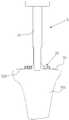
도 4는 본 발명의 일 실시예에 따른 수술모듈에 사용되는 경골용 환자맞춤형 수술기기를 정면에서 본 사시도.
도 5는 도 4의 경골용 환자맞춤형 수술기기를 배면에서 본 사시도.
도 6은 도 4의 경골용 환자맞춤형 수술기기와 경골의 결합상태를 나타내는 참고도.
도 7은 하지의 기계축을 나타내는 참고도.
도 8은 도 4의 경골용 환자맞춤형 수술기기를 이용하여 기계축을 확인하는 방법을 설명하기 위한 참고도.
도 9는 본 발명의 일 실시예에 따른 수술모듈에 사용되는 킬홈형성부재의 사시도.
도 10은 도 9의 킬홈형성부재의 분해사시도.
도 11 내지 12는 본 발명의 일 실시예에 따른 수술모듈을 사용하여 시술부를 형성하는 방법을 설명하기 위한 참고도.Figs. 1 to 3 are reference views for explaining artificial joint replacement for a knee joint.
FIG. 4 is a front view of a patient-customized surgical instrument for use in a surgical module according to an embodiment of the present invention. FIG.
FIG. 5 is a perspective view of the patient-customized surgical instrument for tibia of FIG. 4 as viewed from the back; FIG.
6 is a reference view showing a state of the tibia being engaged with the patient-customized surgical instrument for the tibia of Fig.
7 is a reference view showing a machine axis of a base;
FIG. 8 is a reference diagram for explaining a method of identifying a machine axis using the patient-customized surgical instrument for the tibia of FIG. 4;
9 is a perspective view of a keel forming member used in a surgical module according to an embodiment of the present invention.
10 is an exploded perspective view of the keel forming member of Fig.
11 to 12 are reference views for explaining a method of forming a treatment section using a surgical module according to an embodiment of the present invention.
이하에서는 본 발명에 따른 경골용 환자맞춤형 수술기기를 이용하는 수술모듈을 첨부된 도면을 참조하여 상세히 설명한다. 특별한 정의가 없는 한 본 명세서의 모든 용어는 본 발명이 속하는 기술분야의 통상의 지식을 가진 기술자가 이해하는 당해 용어의 일반적 의미와 동일하고 만약 본 명세서에 사용된 용어의 의미와 충돌하는 경우에는 본 명세서에 사용된 정의에 따른다. 또한, 본 발명의 요지를 불필요하게 흐릴 수 있는 공지 기능 및 구성에 대해 상세한 설명은 생략한다.
Hereinafter, a surgical module using a patient-customized surgical instrument for a tibia according to the present invention will be described in detail with reference to the accompanying drawings. Unless defined otherwise, all terms used herein have the same meaning as commonly understood by one of ordinary skill in the art to which this invention belongs and, if conflict with the meaning of the terms used herein, It follows the definition used in the specification. Further, the detailed description of known functions and configurations that may unnecessarily obscure the subject matter of the present invention will be omitted.
도 1 내지 3은 무릎관절에 대한 인공관절 치환술을 설명하기 위한 참고도이며, 도 4는 본 발명의 일 실시예에 따른 수술모듈에 사용되는 경골용 환자맞춤형 수술기기를 정면에서 본 사시도이고, 도 5는 도 4의 경골용 환자맞춤형 수술기기를 배면에서 본 사시도이며, 도 6은 도 4의 경골용 환자맞춤형 수술기기(지침바는 제외)와 경골의 결합상태를 나타내는 참고도이고, 도 7은 하지의 기계축을 나타내는 참고도이며, 도 8은 도 4의 경골용 환자맞춤형 수술기기를 이용하여 기계축을 확인하는 방법을 설명하기 위한 참고도이고, 도 9는 본 발명의 일 실시예에 따른 수술모듈에 사용되는 킬홈형성부재의 사시도이며, 도 10은 도 9의 킬홈형성부재의 분해사시도이고, 도 11 내지 12는 본 발명의 일 실시예에 따른 수술모듈을 사용하여 시술부를 형성하는 방법을 설명하기 위한 참고도이다.
FIGS. 1 to 3 are reference views for explaining artificial joint replacement for a knee joint, FIG. 4 is a front view of a patient-customized surgical instrument for use in a surgical module according to an embodiment of the present invention, 5 is a perspective view of the patient-customized surgical instrument for tibia of FIG. 4 viewed from the back, FIG. 6 is a reference view showing the state of engagement of the patient-customized surgical instrument (except for the guide bar) FIG. 8 is a reference view for explaining a method of identifying a machine axis using the patient-customized surgical instrument for tibia of FIG. 4, and FIG. 9 is a view for explaining the operation of the surgical module according to an embodiment of the present invention. FIG. 10 is an exploded perspective view of the keel forming member shown in FIG. 9, and FIGS. 11 to 12 illustrate a method of forming a treatment unit using the surgical module according to an embodiment of the present invention. It is a reference diagram for naming.
본 발명의 일 실시예에 따른 경골용 환자맞춤형 수술기기를 이용하는 수술모듈은 경골(200)에 임플란트(경골요소(400))의 이식이 가능하도록 상기 경골(200)에 시술부 형성시 사용되는데, 이하에서는 도 1 내지 12를 참조하여 경골용 환자맞춤형 수술기기를 이용하는 수술모듈을 설명하기로 한다. 상기 수술모듈은 경골(200)의 근위단부(210)에 결합하여 시술부의 절단면(220) 및 포스트홈(231)의 형성시 사용되는 경골용 환자맞춤형 수술기기(1)와, 상기 경골용 환자맞춤형 수술기기(1)가 사용되어 시술부의 절단면(220) 및 포스트홈(231)이 형성된 후 상기 절단면(220)에 결합하여 시술부의 킬홈(232)의 형성시 사용되는 킬홈형성부재(2)를 포함한다. 상기 시술부를 형성한다 함은 임플란트의 이식가능하도록 경골(200)을 가공하는 것을 말하는데, 도 3에는 시술부가 형성된 경골(200)의 모습을 나타낸다. 상기 시술부는 경골요소(400)의 평단부(410)가 안착되는 절단면(220)과, 상기 평단부(410)의 하면에서 돌출되는 포스트(420)와 킬(430)을 수용하는 안착홈(230)을 포함하며, 상기 안착홈(230)은 포스트(420)를 수용하는 포스트홈(231)과 킬(430)을 수용하는 킬홈(232)을 포함한다. 상기 환자맞춤형 수술기기라 함은 환자 개인에 맞추어 제작된 수술기기를 말하는데, 상기 환자맞춤형 수술기기는 시술부를 형성할 손상된 경골을 CT scanning을 하여 상기 경골에 대한 CT data를 획득하고, 상기 CT data를 이용하여 상기 경골의 3D image를 디자인하고(예컨대, 3D 디자인 프로그램이 사용됨), 상기 경골의 3D image에서 시술부 형성시 사용되는 인자(예컨대, 기계축, 절단면, 안착홈 등)을 추출하고, 상기 경골의 3D image와 추출된 인자(이하, '뼈의 3D 데이터'라 함)를 이용하여 경골에 부착되는 수술기기의 3D image를 디자인하고(예컨대, 3D 디자인 프로그램이 사용됨), 상기 수술기기의 3D image를 3D 프린터로 프린팅하여 제작된다. 상기 환자맞춤형 수술기기는 환자에 맞추어 개별적으로 제조되므로, 손상된 경골에 접촉하는 상기 경골용 환자맞춤형 수술기기의 내면에는 상기 경골을 에워싸는, 즉 접촉하는 경골의 음(negative)의 형상을 가진 접촉면(111a, 112a)이 형성되고, 상기 환자맞춤형 수술기기를 구성하는 접촉면(111a, 112a), 커팅부재삽입창(12), 위치설정홀(14), 기계축확인부(15), 절단면가이드(161) 등의 하부 구성은 경골의 3D 데이터에 근거하여 제작되어 환자에 최적화된 형태 및 형성 위치를 가지게 된다. 즉, 상기 환자맞춤형 수술기기를 경골(200)에 정위치시키면, 기계축확인부(15)의 지침바(152)는 경골(200)의 기계축(600)에 일치하고, 상기 위치설정홀(14), 절단면가이드(161)를 통해 목적하는 포스트홈(231), 절단면(220)을 정확하게 형성할 수 있는데, 이에 대해서는 하기에서 자세히 설명하기로 한다. 또한, 상기 환자맞춤형 수술기기는 다양한 소재로 제조되나, 바람직하게는 폴리에틸렌 등의 합성수지로 제작된다.
The surgical module using the patient-customized surgical instrument for tibia according to an embodiment of the present invention is used in forming the operation part in the
상기 경골용 환자맞춤형 수술기기(1)는 경골(200)의 근위단부(210)에 결합하여 경골요소(400)를 이식하기 위한 시술부 형성시 사용되는 구성으로, 몸체부(11), 커팅부재삽입창(12), 고정홀(13), 위치설정홀(14), 기계축확인부(15), 지침자(16) 등을 포함한다.
The patient-customized
상기 몸체부(11)는 경골(200)의 근위단부(210)에 결합하여 경골(200)의 일부를 에워싸는 구성으로, 전측부(111), 상측부(112) 등을 포함한다.The
상기 전측부(111)는 경골(200)의 근위단부(210)의 전측에 위치하여 경골(200)의 일부를 에워싸는 구성으로, 접촉면(111a) 등을 포함한다. 상기 전측부(111)에는 후술할 커팅부재삽입창(12), 고정홀(13), 기계축확인부(15), 절단면가이드(161) 등이 형성될 수 있다.The
상기 접촉면(111a)은 상기 전측부(111)의 내측면에 형성되어 상기 경골(200)의 근위단부(210)의 전측을 에워싸는 즉 접촉하는 경골(200)의 음(negative)의 형상을 가지는 구성으로, 환자 개개인의 경골(200)의 3D 데이터를 근거하여 형성되게 된다.The
상기 상측부(112)는 상기 전측부(111)의 상단에서 절곡연장되어 상기 경골(200)의 근위단부(210)의 상측에 위치하여 경골(200)의 일부를 에워싸는 구성으로, 접촉면(112a) 등을 포함한다. 상기 상측부(112)에는 후술할 위치설정홀(14) 등이 형성될 수 있다.The
상기 접촉면(112a)은 상기 상측부(112)의 내측면에 형성되어 상기 경골(200)의 근위단부(210)의 상측을 에워싸는 즉 접촉하는 경골(200)의 음(negative)의 형상을 가지는 구성으로, 환자 개개인의 경골(200)의 3D 데이터를 근거하여 형성되게 된다.
The
상기 커팅부재삽입창(12)은 상기 전측부(111)에 관통형성되며 절단면(220)을 형성하기 위해 삽입되는 커팅부재(미도시)를 수용하는 구성으로, 환자 개개인의 경골(200)의 3D 데이터를 근거하여 형성되며, 일정 형상을 가지나 바람직하게는 직사각형의 형태를 가진다. 상기 커팅부재는 예컨대 의료용 톱(saw) 등이 사용될 수 있다.
The cutting
상기 고정홀(13)은 상기 커팅부재삽입창(12)과 일정 간격을 두고 상기 전측부(111)에 관통형성되어, 상기 경골(200)과 몸체부(11)를 결합시키기 위한 고정부재(미도시)를 수용하는 구성으로, 상기 고정홀(13)에 삽입된 고정부재의 말단은 상기 경골(200)을 파고들어 상기 경골(200)과 몸체부(11)는 견고하게 고정되게 된다. 상기 고정홀(13)은 전면에서 전후방향으로 관통형성된 제1고정홀(13a)과, 측면에서 비스듬히 관통형성된 제2고정홀(13b)을 포함한다.
The fixing
상기 위치설정홀(14)은 상기 상측부(112)에 관통형성되며, 경골요소(400)의 포스트(420)를 수용하는 포스트홈(231)을 경골(200)에 형성시 사용되는 포스트홈형성부재(2)를 수용하여 가이드하는 구성으로, 상기 위치설정홈(14)은 환자 개개인의 경골(200)의 3D 데이터를 근거하여 형성되게 된다. 상기 위치설정홀(14)에 삽입되는 상기 포스트홈형성부재(2)는 상기 경골(200)을 파고들어 상기 경골(200)에는 상기 포스트홈(231)이 형성되게 된다. 상기 포스트홈형성부재(2)는 예컨대 뼈의 천공을 위해 관용적으로 사용되는 드릴 등이 사용될 수 있다. 상기 위치설정홀(14)는 상기 경골(200)의 3D 데이터에 근거하여 형성되므로, 상기 몸체부(11)가 손상된 경골(200)에 정위치로 결합하는 경우, 상기 위치설정홀(14)에 표스트홈형성부재(2)를 삽입하여 회전시킴으로써, 목적하는 포스트홈(231)을 정확하게 형성할 수 있다. 종래에는 포스트홈(231)을 형성하기 위해서는 경골용 환자맞춤형 수술기기(1)를 통해 절단면(220)을 형성하고 상기 환자맞춤형 수술기기(1)를 제거한 다음 형성할 포스트홈(231)의 위치를 설정한 후 포스트홈형성부재(2)를 사용하여 포스트홈(231)을 형성하는데, 상기 경골용 환자맞춤형 수술기기(1)는 환자 개개인의 경골(200)의 3D 데이터를 근거하여 형성된 상기 위치설정홀(14)이 상기 포스트홈형성부재(2)를 가이드하므로 포스트홈(231)의 형성위치를 따로 설정할 필요가 없어 시술부 형성을 용이하게 할 수 있는 특징이 있다.
The
상기 기계축확인부(15)는 상기 몸체부(11)의 일측에 형성되어 하지(경골(200))의 기계축(600)을 육안으로 확인가능하도록 지침을 제공하는 구성으로, 연결부(151), 지침바(152) 등을 포함한다. 상기 기계축확인부(15)는 환자 개개인의 경골(200)의 3D 데이터를 근거하여 형성되게 된다. 상기 기계축확인부(15)를 설명하기에 앞서 상기 하지의 기계축(600, mechanical axis)을 살펴보면, 도 7에 도시된 바와 같이 하지(대퇴골(100), 경골(200))의 역학적 축을 말한다. 상기 기계축(600)은 정형외과 분야에서 관용적으로 사용하는 지표이므로 자세한 설명은 생략하기로 한다.The machine
상기 연결부(151)는 상기 전측부(111)의 전면에서 돌출형성되어 상기 지침바(152)를 상기 몸체부(11)에 고정하는 구성으로, 상기 연결부(151)는 상하관통형성되어 상기 지침바(152)를 수용하는 결합홀(151a) 등을 포함한다. 상기 연결부(151)는 전측으로 돌출되므로 지침바(152)의 삽입을 용이하게 할 수 있고, 상기 결합홀(151a)은 길이 방향으로 긴 형상을 가져 상기 지침바(152)의 안정적인 안내가 가능하다.The connecting
상기 지침바(152)는 상기 연결부(151)의 결합홀(151a)에 삽입되어 상기 몸체부(11)에 고정되며, 상기 경골(100)의 기계축(600)의 위치를 확인가능하게 하는 구성으로, 상기 지침바(152)는 일정 형상을 가지나 바람직하게는 단면이 원형, 사각형, 육각형 등의 형상을 가진 바의 형태를 가진다. 상기 기계축확인부(15)는 상기 경골(200)의 3D 데이터에 근거하여 형성되므로, 상기 몸체부(11)가 손상된 경골(200)에 정위치로 결합하는 경우, 상기 기계축확인부(15)의 지침바(152)는 상기 경골(200)의 기계축(600)에 일치하게 된다. 즉, 상기 몸체부(11)를 상기 경골(200)의 근위단부(210)에 결합시키고 상기 결합홀(151a)에 지침바(152)를 삽입하여, 상기 지침바(152)의 선단이 경골평면의 과간융기(a, intercondylar eminence of tibia plateau)를 향하게 하고 상기 지침바(152)의 말단이 발목관절(b, talocrural joint)을 향하게 하는 경우, 도 8에 도시된 바와 같이 상기 지침바(152)는 경골(200)의 기계축(600)에 위치하게 된다. 따라서, 상기 몸체부(11)의 상기 경골(200)에 대한 결합위치를 조절하여 상기 지침바(152)를 기계축(600)과 일치시켜 상기 몸체부(11)를 경골(200)에 정위치시킬 수 있다. 인공관절 치환술을 시술한 환자의 보행에 문제가 발생하지 않기 위해서는 상기 경골(200)의 절단면(220)은 상기 기계축(600)과 수직하게 형성되어야 하는데, 상기 환자맞춤형 수술기기는 상기 기계축확인부(15)를 통해 경골(200)의 기계축(600)에 부합하게 상기 몸체부(11)를 상기 경골(200)에 정위치시킬 수 있어, 경골(200)의 절단면(220)을 정확하고 용이하게 형성할 수 있다.
The
상기 지침자(16)는 상기 몸체부(11)의 일측면에 형성되어 시술부 형성시 사용되는 경골(200)의 지표를 육안으로 확인가능하도록 하는 구성으로, 절단면가이드(161) 등을 포함한다. 상기 지침자(16)는 환자 개개인의 경골(200)의 3D 데이터를 근거하여 형성되게 된다.The
상기 절단면가이드(161)는 상기 전측부(111)의 측면에 전후방향으로 형성되어 경골(200)에 형성되어야 할 절단면(220)의 위치를 확인가능하게 하는 구성으로, 환자 개개인의 경골(200)의 3D 데이터를 근거하여 형성되게 된다. 상기 몸체부(11)를 상기 고정부재를 이용하여 상기 경골(200)의 근위단부(210)에 정위치시키고, 상기 커팅부재를 상기 커팅부재삽입창(12)에 삽입하여 상기 절단면가이드(161)를 따라 경골(200)을 절단하면 경골(200)의 절단면(220)이 정확하게 형성되게 된다. 상기 절단면(220)은 상기 지침바(152), 즉 하지의 기계축(600)과 수직하게 형성되게 된다. 상기 몸체부(11)는 일반적으로 폴리에틸렌 등의 합성수지로 제작되므로 커팅부재에 의해 쉽게 파손이 가능하여, 상기 커팅부재를 이용하여 상기 절단면(220) 형성시 상기 몸체부(11)가 상기 커팅부재에 의해 파손되지 않도록 상기 커팅부재삽입창(12)은 상기 커팅부재보다 훨씬 크게 형성하는데, 상기 환자맞춤형 수술기기는 상기 절단면가이드(161)가 상기 커팅부재의 위치를 가이드하므로 상기 몸체부(11)가 파손되지 않으면서 절단면(220)을 정확하게 형성할 수 있게 된다.
The
상기 킬홈형성부재(3)는 상기 경골용 환자맞춤형 수술기기(1)가 사용되어 시술부의 절단면(220) 및 포스트홈(231)이 형성된 후 상기 경골(200)의 절단면(220)에 결합하여 시술부의 킬홈(232)의 형성시 사용되는 구성으로, 케이싱(31), 지지플레이트(32), 킬홈형성부(33), 고정핀(34) 등을 포함한다.
The
상기 케이싱(31)은 말단이 상기 포스트홈(231)에 삽입되며 승하강하는 킬홈형성부(33)를 수용하는 구성으로, 날개돌출홀(311)을 포함한다. 상기 케이싱(31)은 일정 형상을 가지나 바람직하게는 상하관통된 원통형의 형상을 가진다.The
상기 날개돌출홀(311)은 상기 케이싱(31)의 외측면 말단에서 상측으로 일정 길이 관통형성되는 구성으로, 상기 날개돌출홈(311)을 통해 상기 킬홈형성부(33)의 날개부(332)가 돌출된다.
The
상기 지지플레이트(32)는 상기 케이싱(31)의 외측면 하측에 결합하여 상기 경골(200)의 절단면(220)에 접하는 구성으로, 상기 지지플레이트(32)는 상하관통형성되며 날개부(332)의 승하강시 이동통로가 되는 가이드홀(321)과, 상기 가이드홀(321)과 일정 간격을 두고 상하관통 형성되며 고정핀(34)이 삽입되는 핀삽입홀(322)을 포함한다.
The
상기 킬홈형성부(33)는 상기 케이싱(31) 내에 위치하여 승하강하는 승하강바(331)와 상기 승하강바(331)의 외측면 하측에 형성되며 상기 날개돌출홀(311)을 통해 상기 케이싱(31) 외부에 돌출되고 킬홈(232)에 대응되는 형상을 가진 날개부(332)를 포함하여, 상기 경골(200)에 킬홈(232)을 형성한다.The
상기 승하강바(331)는 상기 케이싱(31) 내에 위치하여 승하강하는 구성으로, 나사결합하는 제1승하강바(331a)와 제2승하강바(331b)를 포함한다. 상기 제1승하강바(331a)의 상단에는 승하강바(331)의 하강깊이를 제한하는 컬림턱(331c)이 형성된다.The lifting
상기 날개부(332)는 상기 제2승하강바(331)의 외측면에 돌출형성되어 상기 날개돌출홀(311)을 통해 상기 케이싱(31)의 외부로 돌출되어 상기 승하강바(311)와 함께 승하강하여 경골(200)의 킬홈(232)를 형성한다.
The
상기와 같은 구성을 가지는 수술모듈을 이용하여 경골(200)에 시술부를 형성하는 방법을 도 1 내지 12를 참조하여 살펴보면, 도 8에 도시된 바와 같이 몸체부(11)를 경골(200)의 근위단부(210)에 위치시키고, 상기 결합홀(151a)에 지침바(152)를 삽입하여 상기 지침바(152)의 선단이 경골평면의 과간융기(a)를 향하게 하고 상기 지침바(152)의 말단이 발목관절(b)을 향하게 하여, 상기 지침바(152)를 경골(200)의 기계축(600)에 일치시킨 후 상기 몸체부(11)를 상기 경골(200)의 근위단부(210)에 고정하고 치침바(152)를 제거한다. 이후, 도 11에 도시된 바와 같이 상기 위치설정홀(14)에 상기 포스트홈형성부재(2)를 삽입하여 상기 경골(200)에 상기 포스트홈(231)을 형성하고, 상기 포스트홈형성부재(2)를 제거된 상태에서 상기 커팅부재를 상기 커팅부재삽입창(12)에 삽입하여 상기 절단면가이드(161)를 따라 경골(200)을 절단하면 경골(200)의 기계축(600)과 수직한 절단면(220)이 형성된다. 이후, 커팅부재, 경골용 환자맞춤형 수술기기(1) 및 절삭된 골을 경골(200)에서 제거하고, 상기 케이싱(31)의 말단을 포스트홈(231)에 삽입하고 지지플레이트(32)를 절단면(220)에 결합시켜 상기 킬홈형성부재(3)를 상기 경골(200)에 부착한 다음, 도 12에 도시된 바와 승하강바(331)를 말단을 밀어 하강시키면 상기 날개부(332)가 하강하여 킬홈(232)가 형성되게 된다. 상기 킬홈(232)이 형성된 후에 상기 킬홈형성부재(3) 및 절삭된 골을 제거하면 도 3에 도시된 바와 같이 경골(200)에 시술부가 형성되게 된다.
Referring to FIGS. 1 to 12, a method of forming a treatment portion on the
이상에서, 출원인은 본 발명의 다양한 실시예들을 설명하였지만, 이와 같은 실시예들은 본 발명의 기술적 사상을 구현하는 일 실시예일 뿐이며, 본 발명의 기술적 사상을 구현하는 한 어떠한 변경예 또는 수정예도 본 발명의 범위에 속하는 것으로 해석되어야 한다.While the present invention has been described in connection with what is presently considered to be practical exemplary embodiments, it is to be understood that the invention is not limited to the disclosed embodiments, but, on the contrary, Should be interpreted as falling within the scope of.
1: 경골용 환자맞춤형 수술기기 11: 몸체부
12: 커팅부재삽입창 13: 고정홀 14: 위치설정홀
15: 기계축확인부 16: 지침자 13a: 제1고정홀
13b: 제2고정홀 111: 전측부 112: 상측부
151: 연결부 152: 지침바 161: 절단면가이드
151a: 결합홀 2: 포스트홈형성부재 3: 킬홈형성부재
31: 케이싱 32: 지지플레이트 33: 킬홈형성부
34: 고정핀 311: 날개돌출홀 321: 가이드홀
322: 핀삽입홀 331: 승하강바 332: 날개부
331a: 제1승하강바 331b: 제2승하강바 331c: 걸림턱1: patient-customized surgical instrument for tibia 11:
12: Cutting member inserting window 13: Fixing hole 14: Positioning hole
15: Machine shaft confirmation part 16:
13b: second fixing hole 111: front side portion 112: upper side portion
151: connection part 152: guide bar 161:
151a: Coupling hole 2: Post groove forming member 3: Kill groove forming member
31: casing 32: support plate 33: keyhole forming part
34: fixing pin 311: wing protrusion hole 321: guide hole
322: pin insertion hole 331: ascending / descending bar 332:
331a:
Claims (8)
Translated fromKorean상기 환자맞춤형 수술기기는 경골의 근위단부의 전측에 위치하여 상기 경골의 일부에 접촉하여 에워싸며 접촉하는 경골의 음의 형상을 가지는 접촉면을 포함하는 전측부와, 상기 전측부의 상단에서 절곡연장되어 상기 경골의 근위단부의 상측에 위치하여 경골의 일부에 접촉하여 에워싸며 접촉하는 경골의 음의 형상을 가지는 접촉면을 포함하는 상측부로 이루어지는 몸체부와; 상기 몸체부의 일측에 관통형성되며 경골의 절단면을 형성하기 위해 삽입되는 커팅부재를 수용하는 커팅부재삽입창과; 상기 몸체부의 상측부에 관통형성되며, 경골요소의 포스트를 수용하는 포스트홈을 경골에 형성하기 위해 사용되는 포스트홈형성부재를 수용하여 가이드하며 경골의 3D 데이터를 근거하여 형성되는 위치설정홀;을 포함하는 것을 특징으로 하는 경골용 환자맞춤형 수술기기.The present invention relates to a patient-customized surgical instrument used for forming a treatment portion on the tibia so as to enable transplantation of a tibia component to the tibia,
The patient-customized surgical instrument includes a front portion which is located on the front side of the proximal end of the tibia and which is in contact with a portion of the tibia and includes a contact surface having a negative shape of a contacting tibia, A body portion which is located on the upper side of the proximal end of the tibia and is in contact with a portion of the tibia and includes an upper portion including a contact surface having a negative shape of the tibia contacting with the body; A cutting member insertion window formed at one side of the body to receive a cutting member inserted to form a cut surface of the tibia; A positioning hole formed in the upper portion of the body portion to receive and guide a post groove forming member used to form a post groove for receiving the post of the tibia component on the tibia and formed on the basis of 3D data of the tibia; Wherein the tibial bone is attached to the patient's body.
상기 경골용 환자맞춤형 수술기기는 상기 몸체부의 일측에 형성되어 경골의 기계축을 육안으로 확인가능하도록 지침을 제공하는 기계축확인부를 추가로 포함하며,
상기 기계축확인부는 상기 몸체부의 전측에서 돌출형성되어 지침바를 상기 몸체부에 고정하는 연결부와; 상기 연결부에 결합되어 상기 몸체부에 고정되며, 상기 기계축의 위치를 확인가능하게 하는 지침바;를 포함하여, 상기 지침바의 일단이 경골평면의 과간융기를 향하게 하고 상기 지침바의 타단이 발목관절을 향하게 하는 경우 상기 지침바는 경골의 기계축과 일치하게 되는 것을 특징으로 하는 경골용 환자맞춤형 수술기기.The method according to claim 1,
The patient-customized surgical instrument for a tibia further includes a machine axis check part formed at one side of the body part to provide instructions for visually checking the machine axis of the tibia,
Wherein the machine axis check part is protruded from a front side of the body part and fixes the guide bar to the body part; And a guide bar coupled to the connection portion and fixed to the body portion to enable the position of the machine shaft to be confirmed, wherein one end of the pointer bar faces the overhang of the tibia plane, and the other end of the pointer bar is connected to the ankle joint Wherein the guide bar is aligned with a machine axis of the tibia.
상기 몸체부의 일측에 형성되어 경골에 형성되어야 할 절단면의 위치의 확인이 가능하도록 지침을 제공하는 절단면가이드를 추가로 포함하는 것을 특징으로 하는 경골용 환자맞춤형 수술기기.[2] The surgical instrument according to claim 1, wherein the patient-
Further comprising a cut surface guide formed on one side of the body to provide a guide so that a position of a cut surface to be formed on the tibia can be confirmed.
상기 수술모듈은 경골의 근위단부에 결합하여 시술부의 절단면 및 포스트홈의 형성시 사용되는 제1항 내지 제4항 중 어느 한 항의 경골용 환자맞춤형 수술기기와, 상기 경골용 환자맞춤형 수술기기가 사용되어 시술부의 절단면 및 포스트홈이 형성된 후 상기 절단면에 결합하여 시술부의 킬홈의 형성시 사용되는 킬홈형성부재를 포함하며,
상기 경골용 환자맞춤형 수술기기는 청구항 제1항에 있어서의 경골용 환자맞춤형 수술기기인 것을 특징으로 하는 경골용 환자맞춤형 수술기기를 이용하는 수술모듈.A surgical module using a patient-customized surgical instrument for use in forming a treatment portion on the tibia to enable transplantation of a tibia component in the tibia,
Wherein the surgical module is the patient-customized surgical instrument for a tibia according to any one of claims 1 to 4, which is used when forming a cut surface and a post groove of a treatment section by being coupled to a proximal end of the tibia, And a keyhole forming member coupled to the cut surface of the treatment unit and the cut surface after the posthole is formed to form a keyhole of the treatment unit,
Wherein the patient-customized surgical instrument for the tibia is a patient-customized surgical instrument for the tibia according to claim 1.
일단이 상기 포스트홈에 삽입되며 승하강하는 킬홈형성부를 수용하는 케이싱과; 상기 케이싱의 외측면에 결합하여 상기 경골의 절단면에 접하는 지지플레이프와; 상기 케이싱 내에 위치하여 승하강하는 승하강바와. 상기 승하강바의 외측면 하측에 형성되며 상기 케이싱의 날개돌출홀을 통해 상기 케이싱의 외부에 돌출되어 상기 승하강바와 함께 승하강하여 경골에 킬홈을 형성하는 날개부를 가지는 킬홈형성부;를 포함하는 것을 특징을 하는 경골용 환자맞춤형 수술기기를 이용하는 수술모듈.6. The apparatus according to claim 5, wherein the keel forming member
A casing having one end inserted into the post groove and accommodating the keyhole forming portion; A support flap coupled to the outer surface of the casing and contacting the cut surface of the tibia; And an ascending and descending bar located in the casing and ascending and descending. And a blade portion formed on an outer side surface of the rising / falling bar and having a blade protruding outside the casing through a blade protrusion hole of the casing so as to rise and fall together with the rising and falling bars to form a trough in the tibia A surgical module that utilizes a patient-tailored surgical instrument for the tibia.
상하관통형성되며 날개부의 승하강시 이동통로가 되는 가이드홀을 포함하는 것을 특징으로 하는 경골용 환자맞춤형 수술기기를 이용하는 수술모듈.7. The apparatus of claim 6, wherein the support plate
And a guide hole formed in the upper and lower portions and serving as a movement passage for ascending and descending the wing portion.
상기 승하강바의 상단에는 승하강바의 하강깊이를 제한하는 컬림턱이 형성되는 것을 특징으로 하는 경골용 환자맞춤형 수술기기를 이용하는 수술모듈.The method according to claim 6,
And a curling step for limiting a falling depth of the elevating bar is formed at the upper end of the elevating bar.
Priority Applications (5)
| Application Number | Priority Date | Filing Date | Title |
|---|---|---|---|
| KR1020130162144AKR101553311B1 (en) | 2013-12-24 | 2013-12-24 | Patient specific surgical instrument for tibia |
| EP14873617.6AEP3087938A4 (en) | 2013-12-24 | 2014-10-23 | Patient-customized surgical instrument for tibia and surgical module using same |
| PCT/KR2014/010013WO2015099275A1 (en) | 2013-12-24 | 2014-10-23 | Patient-customized surgical instrument for tibia and surgical module using same |
| CN201480067989.6ACN105813587A (en) | 2013-12-24 | 2014-10-23 | Patient-customized surgical instrument for tibia and surgical module using same |
| US15/101,141US11129625B2 (en) | 2013-12-24 | 2014-10-23 | Patient-customized surgical instrument for tibia and surgical module using same |
Applications Claiming Priority (1)
| Application Number | Priority Date | Filing Date | Title |
|---|---|---|---|
| KR1020130162144AKR101553311B1 (en) | 2013-12-24 | 2013-12-24 | Patient specific surgical instrument for tibia |
Publications (2)
| Publication Number | Publication Date |
|---|---|
| KR20150074396A KR20150074396A (en) | 2015-07-02 |
| KR101553311B1true KR101553311B1 (en) | 2015-09-15 |
Family
ID=53479093
Family Applications (1)
| Application Number | Title | Priority Date | Filing Date |
|---|---|---|---|
| KR1020130162144AActiveKR101553311B1 (en) | 2013-12-24 | 2013-12-24 | Patient specific surgical instrument for tibia |
Country Status (5)
| Country | Link |
|---|---|
| US (1) | US11129625B2 (en) |
| EP (1) | EP3087938A4 (en) |
| KR (1) | KR101553311B1 (en) |
| CN (1) | CN105813587A (en) |
| WO (1) | WO2015099275A1 (en) |
Families Citing this family (10)
| Publication number | Priority date | Publication date | Assignee | Title |
|---|---|---|---|---|
| DE102016200131A1 (en)* | 2016-01-08 | 2016-04-07 | Rz-Medizintechnik Gmbh | Method for producing a surgical instrument |
| US10398417B2 (en)* | 2016-06-29 | 2019-09-03 | DePuy Synthes Products, Inc. | Systems and methods for manufacturing custom surgical instruments |
| KR101951227B1 (en)* | 2017-03-24 | 2019-04-30 | 주식회사 코렌텍 | Apparatus for Holding Baseplate Trial and Knee Joint Implant Surgical Instrument Set |
| KR102053600B1 (en)* | 2017-07-25 | 2019-12-11 | 주식회사 코렌텍 | Patient-Specific Artificial Shoulder Joint Surgical Instruments |
| KR102019889B1 (en) | 2017-08-24 | 2019-09-10 | 주식회사 코렌텍 | Smart surgical instruments for artificial joint replacement |
| CN107913121A (en)* | 2017-11-22 | 2018-04-17 | 湖南华翔增量制造股份有限公司 | Lower limb mechanical axis calibrating installation |
| KR102162651B1 (en)* | 2018-07-10 | 2020-10-08 | 주식회사 코렌텍 | Gap Gauge to check the Flexion Gap before Posterior Cutting |
| KR102186308B1 (en)* | 2019-01-28 | 2020-12-03 | 주식회사 코렌텍 | Smart surgical instruments for artificial joint replacement |
| CN111528969A (en)* | 2020-04-27 | 2020-08-14 | 北京力达康科技有限公司 | Proximal tibia medullary cavity treatment device |
| KR102443253B1 (en)* | 2022-01-12 | 2022-09-15 | 주식회사 셀루메드 | Patient-Specific Pin Guide for Total Knee Arthroplasty for Minimally Invasive Total Knee Arthroplasty |
Citations (2)
| Publication number | Priority date | Publication date | Assignee | Title |
|---|---|---|---|---|
| KR100925282B1 (en)* | 2007-06-26 | 2009-11-05 | 이송 | Cutting guide module for knee joint surgery and method of use |
| US20120310399A1 (en)* | 2011-06-06 | 2012-12-06 | Biomet Manufacturing Corp. | Pre-operative planning and manufacturing method for orthopedic procedure |
Family Cites Families (16)
| Publication number | Priority date | Publication date | Assignee | Title |
|---|---|---|---|---|
| US5282866A (en)* | 1992-02-12 | 1994-02-01 | Osteonics Corp. | Prosthetic knee tibial component with axially ribbed keel and apparatus for effecting implant |
| US5690636A (en)* | 1995-12-21 | 1997-11-25 | Johnson & Johnson Professional, Inc. | Punch system for tibial prosthesis |
| US7534263B2 (en)* | 2001-05-25 | 2009-05-19 | Conformis, Inc. | Surgical tools facilitating increased accuracy, speed and simplicity in performing joint arthroplasty |
| US5976147A (en)* | 1997-07-11 | 1999-11-02 | Johnson & Johnson Professional, Inc | Modular instrumentation for bone preparation and implant trial reduction of orthopedic implants |
| US6063091A (en)* | 1998-10-13 | 2000-05-16 | Stryker Technologies Corporation | Methods and tools for tibial intermedullary revision surgery and associated tibial components |
| US7390327B2 (en)* | 2003-10-03 | 2008-06-24 | Howmedica Osteonics Corp. | Punch apparatus and method for surgery |
| KR100562518B1 (en)* | 2004-08-16 | 2006-03-21 | 서재곤 | Tibia Osteotomy |
| US8591516B2 (en)* | 2006-02-27 | 2013-11-26 | Biomet Manufacturing, Llc | Patient-specific orthopedic instruments |
| GB2447702A (en)* | 2007-03-23 | 2008-09-24 | Univ Leeds | Surgical bone cutting template |
| WO2012112694A2 (en)* | 2011-02-15 | 2012-08-23 | Conformis, Inc. | Medeling, analyzing and using anatomical data for patient-adapted implants. designs, tools and surgical procedures |
| US9084618B2 (en)* | 2011-06-13 | 2015-07-21 | Biomet Manufacturing, Llc | Drill guides for confirming alignment of patient-specific alignment guides |
| KR101190973B1 (en) | 2011-07-08 | 2012-10-15 | 성균관대학교산학협력단 | Apparatus and method for displaying amputation plane of knee joint |
| US8556900B2 (en)* | 2011-12-01 | 2013-10-15 | Zimmer, Inc. | Surgical instrument for impacting and extracting a cutting instrument |
| US9486226B2 (en)* | 2012-04-18 | 2016-11-08 | Conformis, Inc. | Tibial guides, tools, and techniques for resecting the tibial plateau |
| US10327786B2 (en)* | 2012-05-24 | 2019-06-25 | Zimmer, Inc. | Patient-specific instrumentation and method for articular joint repair |
| CN104955421A (en)* | 2012-10-18 | 2015-09-30 | 史密夫和内修有限公司 | Alignment devices and methods |
- 2013
- 2013-12-24KRKR1020130162144Apatent/KR101553311B1/enactiveActive
- 2014
- 2014-10-23CNCN201480067989.6Apatent/CN105813587A/enactivePending
- 2014-10-23USUS15/101,141patent/US11129625B2/enactiveActive
- 2014-10-23WOPCT/KR2014/010013patent/WO2015099275A1/enactiveApplication Filing
- 2014-10-23EPEP14873617.6Apatent/EP3087938A4/ennot_activeWithdrawn
Patent Citations (2)
| Publication number | Priority date | Publication date | Assignee | Title |
|---|---|---|---|---|
| KR100925282B1 (en)* | 2007-06-26 | 2009-11-05 | 이송 | Cutting guide module for knee joint surgery and method of use |
| US20120310399A1 (en)* | 2011-06-06 | 2012-12-06 | Biomet Manufacturing Corp. | Pre-operative planning and manufacturing method for orthopedic procedure |
Also Published As
| Publication number | Publication date |
|---|---|
| EP3087938A4 (en) | 2017-11-01 |
| EP3087938A1 (en) | 2016-11-02 |
| CN105813587A (en) | 2016-07-27 |
| US11129625B2 (en) | 2021-09-28 |
| US20160302800A1 (en) | 2016-10-20 |
| WO2015099275A1 (en) | 2015-07-02 |
| KR20150074396A (en) | 2015-07-02 |
Similar Documents
| Publication | Publication Date | Title |
|---|---|---|
| KR101553311B1 (en) | Patient specific surgical instrument for tibia | |
| US11911046B2 (en) | Patient specific surgical guide locator and mount | |
| US20240372894A1 (en) | Ankle replacement system and method | |
| EP3142570B1 (en) | Humeral cut guide | |
| EP3035872B1 (en) | Bone resection guide and method of manufacture | |
| KR101515144B1 (en) | Patient specific surgical instrument with cutting guide | |
| CN102670275A (en) | Customized patient-specific orthopaedic surgical instrument | |
| CN104869919A (en) | Surgical perforation guide | |
| CN104507403A (en) | Surgical guides from scanned implant data | |
| EP3200702A1 (en) | Tibial tubercle osteotomy guide | |
| CN104997547B (en) | Total knee arthroplasty digitizes deep guide plate preparation method and device | |
| US20230310012A1 (en) | Modular guide system for surgical procedures | |
| US11123194B2 (en) | System of designing a guide tool and/or surgical kit tools and/or an implant comprising a positioning mark | |
| KR101561227B1 (en) | Patient specific surgical instrument for alignment check | |
| US10285713B2 (en) | Guide device for knee replacement | |
| CN204562290U (en) | The deep guide plate arrangement of a kind of Total knee arthroplasty distal femur | |
| KR101561232B1 (en) | Patient specific surgical instrument with indicator | |
| KR20240120360A (en) | Patient Specific Surgical Instrument that is Precisely Placed in a Pre-Planned Position Through Point Contact | |
| KR101806801B1 (en) | Cutting blocks and keel groove guide for knee arthroplasty |
Legal Events
| Date | Code | Title | Description |
|---|---|---|---|
| A201 | Request for examination | ||
| PA0109 | Patent application | Patent event code:PA01091R01D Comment text:Patent Application Patent event date:20131224 | |
| PA0201 | Request for examination | ||
| E902 | Notification of reason for refusal | ||
| PE0902 | Notice of grounds for rejection | Comment text:Notification of reason for refusal Patent event date:20150421 Patent event code:PE09021S01D | |
| PG1501 | Laying open of application | ||
| E701 | Decision to grant or registration of patent right | ||
| PE0701 | Decision of registration | Patent event code:PE07011S01D Comment text:Decision to Grant Registration Patent event date:20150821 | |
| GRNT | Written decision to grant | ||
| PR0701 | Registration of establishment | Comment text:Registration of Establishment Patent event date:20150909 Patent event code:PR07011E01D | |
| PR1002 | Payment of registration fee | Payment date:20150910 End annual number:3 Start annual number:1 | |
| PG1601 | Publication of registration | ||
| FPAY | Annual fee payment | Payment date:20180911 Year of fee payment:4 | |
| PR1001 | Payment of annual fee | Payment date:20180911 Start annual number:4 End annual number:4 | |
| FPAY | Annual fee payment | Payment date:20190910 Year of fee payment:5 | |
| PR1001 | Payment of annual fee | Payment date:20190910 Start annual number:5 End annual number:5 | |
| PR1001 | Payment of annual fee | Payment date:20200910 Start annual number:6 End annual number:6 | |
| PR1001 | Payment of annual fee | Payment date:20210907 Start annual number:7 End annual number:7 | |
| PR1001 | Payment of annual fee | Payment date:20240716 Start annual number:10 End annual number:10 |